

Page 1
WARRANTY
Great Planes®Model Manufacturing Co. guarantees this kit to be free from defects in both material and workmanship at the date of purchase.
This warranty does not cover any component parts damaged by use or modification. In no case shall Great Planes’ liability exceed the
original cost of the purchased kit. Fur ther, Great Planes reserves the right to change or modify this warranty without notice.
In that Great Planes has no control over the final assembly or material used for final assembly, no liability shall be assumed nor accepted for
any damage resulting from the use by the user of the final user-assembled product.By the act of using the user-assembled product, the user
accepts all resulting liability.
If the buyer is not prepared to accept the liability associated with the use of this product, the buyer is advised to return this kit
immediately in new and unused condition to the place of purchase.
To make a warranty claim send the defective part or item to Hobby Services at the address below:
Hobby Services
3002 N. Apollo Dr., Suite 1
Champaign, IL 61822
USA
Include a letter stating your name, return shipping address, as much contact information as possible (daytime telephone number, fax number,
e-mail address), a detailed description of the problem and a photocopy of the purchase receipt. Upon receipt of the package the problem will
be evaluated as quickly as possible.
READ THROUGH THIS MANUAL BEFORE STARTING
CONSTRUCTION.IT CONT AINS IMPOR T ANT INSTR UCTIONS
AND WARNINGS CONCERNING THE ASSEMBLY AND
USE OF THIS MODEL.
GPMZ0184 for GPMA1195 V1.0© Copyright 2005
Champaign, Illinois
(217) 398-8970, Ext 5
airsupport@greatplanes.com
INSTRUCTION MANUAL
Wingspan: 34.75 in [883 mm]
Wing Area: 337 sq in [21.7dm2]
Weight: 15 – 16 oz [425-455g]
Wing Loading: 6.7 – 7.1 oz/sq ft [20-22g/dm2]
Length: 35 in [889 mm]
Radio: 4-channel w/ three micro ser vos and 20 Amp ESC
Motor: Supplied S380 Motor w/ 5:1 gearbox
Page 2
2
INTRODUCTION ...............................................................2
AMA...................................................................................2
SAFETY PRECAUTIONS..................................................3
LITHIUM BATTERY HANDLING & USAGE .....................3
DECISIONS YOU MUST MAKE........................................3
Transmitter...................................................................3
Servos .........................................................................3
Receiver ......................................................................4
Battery.........................................................................4
Speed Control .............................................................4
Charger .......................................................................4
Battery Charging Leads ..............................................4
Glue.............................................................................4
ADDITIONAL ITEMS REQUIRED.....................................4
Radio Equipment .........................................................4
Adhesives & Building Supplies....................................4
Optional Supplies & Tools ...........................................5
IMPORTANT BUILDING NOTES ......................................5
ORDERING REPLACEMENT PARTS ..............................5
METRIC CONVERSIONS .................................................5
KIT INSPECTION..............................................................6
KIT CONTENTS ................................................................6
BUILDING INSTRUCTIONS..............................................7
Join the Wing Halves...................................................7
Join the Wing to the Fuselage.....................................7
Install the Tail Surfaces................................................8
Hinge the Ailerons.......................................................8
Install the Servos.........................................................9
Install the Control Horns and Pushrods....................10
Install the Motor & Speed Control.............................11
Final Setup................................................................12
Optional Combat Setup.............................................13
GET THE MODEL READY TO FLY .................................13
Check the Control Directions ....................................13
Set the Control Throws..............................................13
Balance the Model (C.G.)..........................................14
Balance the Model Laterally ......................................14
PREFLIGHT.....................................................................15
Identify Your Model ....................................................15
Charge the Batteries .................................................15
Balance the Propellers..............................................15
Ground Check...........................................................15
Range Check.............................................................15
MOTOR SAFETY PRECAUTIONS .................................15
AMA SAFETY CODE (excerpts)....................................16
General......................................................................16
Radio Control ............................................................16
CHECK LIST ...................................................................16
FLYING ............................................................................16
Launch.......................................................................17
Flight..........................................................................17
Landing......................................................................17
The Great Planes Fun Force
™
EP Zero ARF is an excellent
way to enjo y 3D aerobatics and combat dogfighting without the
cost and headaches of larger, high-pow ered models.A couple
of hours on the workbench, and your EP Zero ARF will be
ready for sport aerobatics and some mild 3D-type maneuvers,
and more! If you tire of aerobatics, strap a streamer onto the
supplied combat mount and experience the thrill of close-in
combat dogfighting.With two or more of the Fun Force series
combat aircraft, you can recreate classic dogfights of history!
For the latest technical updates or manual corrections to the
EP Zero ARF, visit the Great Planes web site at
www.greatplanes.com
. Open the “Airplanes” link, and then
select the EP Zero ARF. If there is new technical information
or changes to this model a “tech notice” box will appear in
the upper left corner of the page.
We urge you to join the AMA (Academy of Model
Aeronautics) and a local R/C club.The AMA is the governing
body of model aviation and membership is required to fly at
AMA clubs.Though joining the AMA provides many benefits,
one of the primary reasons to join is liability protection.
Coverage is not limited to flying at contests or on the club
field. It even applies to flying at public demonstrations and
air shows. Failure to comply with the Safety Code (excerpts
printed in the back of the manual) may endanger insurance
coverage.Additionally, training programs and instructors are
available at AMA club sites to help you get started the right
way. There are over 2,500 AMA chartered clubs across the
country. Contact the AMA at the address or toll-free phone
number below.
IMPORTANT!!! Two of the most important things you can do
to preserve the radio controlled aircraft hobby are to avoid
flying near full-scale aircraft and avoid flying near or over
groups of people.
Academy of Model Aeronautics
5151 East Memorial Drive
Muncie, IN 47302
Tele: (800) 435-9262
Fax (765) 741-0057
Or via the Internet at:
http://www.modelaircraft.org
AMA
INTRODUCTIONTABLE OF CONTENTS
Page 3

1. Your EP Zero ARF should not be considered a toy, but
rather a sophisticated, working model that functions very
much like a full-size airplane. Because of its performance
capabilities, the EP Zero ARF, if not assembled and
operated correctly, could possibly cause injury to yourself or
spectators and damage to property.
2. You must assemble the model according to the
instructions. Do not alter or modify the model, as doing so
may result in an unsafe or unflyable model. In a few cases
the instructions may differ slightly from the photos.In those
instances the written instructions should be considered
as correct.
3.You must take time to build straight, true and strong.
4. You must use an R/C radio system that is in first-class
condition, and a correctly sized motor and components
(ESC, wheels, etc.) throughout the building process.
5.You must correctly install all R/C and other components so
that the model operates correctly on the ground and in the air .
6.You must check the operation of the model before every
flight to insure that all equipment is operating and that the
model has remained structurally sound. Be sure to check
clevises or other connectors often and replace them if they
show any signs of wear or fatigue.
7. If you are not an experienced pilot or have not flown this
type of model before, we recommend that you get the
assistance of an experienced pilot in your R/C club for your
first flights.If you’ re not a member of a club, your local hob by
shop has information about clubs in your area whose
membership includes experienced pilots.
8.While this kit has been flight tested to exceed normal use,
if the plane will be used for extremely high-stress flying,
such as racing, or if an motor larger than one in the
recommended range is used, the modeler is responsible for
taking steps to reinforce the high-stress points and/or
substituting hardware more suitable for the increased stress .
Remember:Take your time and follow the instructions to
end up with a well-built model that is straight and true.
WARNING!! Failure to follow all instructions could cause
permanent damage to the battery and its surroundings, and
cause bodily harm!
• ONLY use a LiPo approved charger. NEVER use a
NiCd/NiMH peak charger!
• NEVER charge in excess of 4.20V per cell.
• ONLY charge through the “charge” lead. NEVER charge
through the “discharge” lead.
• NEVER charge at currents greater than 1C.
• ALWAYS set charger’ s output v olts to match battery volts.
• ALWAYS charge in a fireproof location.
• NEVER trickle charge.
• NEVER allow the battery temperature to exceed
50°F (65°C).
• NEVER disassemble or modify pack wiring in any way or
puncture cells.
• NEVER discharge below 2.5V per cell.
• NEVER place on combustible materials or leave
unattended during charge or discharge.
• ALWAYS KEEP OUT OF REACH OF CHILDREN.
In the hands of a capable pilot the EP Zero ARF is an
impressive 3D performer. But for the EP Zero ARF to
perform to its full potential, it must be properly equipped with
all the right gear (servos, batteries, receiver, and speed
control). There may be more than one type and brand of
radio equipment that can be used, but based on extensive
testing, following is the equipment we recommend so you
can get the most performance out of your EP Zero ARF and
assemble it as shown in this instruction manual.
With a standard, four-channel radio the EP Zero ARF is
capable of all the basic 3D maneuvers. However, some
advanced pilots who are already familiar with handling
“foamies”may pref er to fly the EP Zero ARF with a computer
radio capable of endpoint adjustments (for fine-tuning
control throws), exponentials (f or “softening”the throws near
the center of the travel), and various mixing functions (such
as rudder-to-elevator mixing for extended knife-edge flight).
The EP Zero ARF requires three
micro
servos with a minimum
torque rating of 15 oz-in. Futaba®S-3108 micro servos
(FUTM0042) are ideal because they meet the torque and weight
requirements. Although there may be other servos that will
physically fit in the model, those outside the recommended
Servos
Transmitter
DECISIONS YOU MUST MAKE
LITHIUM BATTERY HANDLING & USAGE
We, as the kit manuf acturer, provide you with a top quality ,
thoroughly tested kit and instructions, but ultimately the
quality and flyability of your finished model depends on
how you build it; therefore, we cannot in any way
guarantee the performance of your completed model, and
no representations are expressed or implied as to the
performance or safety of your completed model.
PRO TECT YOUR MODEL,YOURSELF
& OTHERS...FOLLOW THESE
IMPORTANT SAFETY PRECAUTIONS
3
Page 4

weight and torque specifications will adversely affect flight
performance and are not recommend. Note: Dur ing assembly
when it’s time to mount the servos, y ou will be instructed to glue
them in. Do not be alarmed as this is a common practice with
this type of lightweight, high-performance model. Should ser vo
removal e v er be necessary for repair, replacement or transf er to
another model this can be done by prying them out with a hobby
knife or a small screwdriver.
The lightest, four-channel receiver is recommended and must
be compatible with whatever servos will be used (not all servos
are compatible with all receivers–even servos and receivers
within the same brand). The Futaba R-114F
Micro
receiver is
recommended and is compatible with the 3108 servos
recommended.Note:Futaba receivers are sold on high and low
bands and come without crystals. Following are the order
numbers for the R-114F receiver and compatible crystals:
Low Band High Band
(Channels 11-35) (Channels 36-60)
R114F Receiver FUTL0442 FUTL0443
Crystal FUTL62** FUTL63**
**Replace the “**” in the order number for the crystals with
the preferred channel number .For example, if you want to fly
on channel 33, order a low band receiver and crystal
number FUTL6233.
The EP Zero ARF requires a 3-cell (11.1V), 1250–1500mAh
lithium-polymer (LiPo) battery capable of providing 7A
continuous discharge current. The ElectriFly™3-cell,
3-Series
1250mAh battery pack is recommended (GPMP0823).
An electronic speed control capable of handling a minimum
of 15A continuous current is required. Additionally, the
speed control should be as light as possible.The ElectriFly
C-25 High-Frequency ESC w/BEC (GPMM2025) is suitable.
A charger capable of charging 3-cell (11.1V) LiPo batteries
such as the ElectriFly PolyCharge 1 to 3-cell LiPo charger
(GPMM3010) must be used. If using another charger, it
must be a LiPo charger or have a LiPo charge mode.Never
charge LiPo batteries with chargers not intended for LiPo
batteries or chargers on NiMH or NiCd settings.
Overcharging or explosion may result. In addition to the
PolyCharge, the ElectriFly Triton™(GPMM3150) or AccuCycle Elite™(HCAP0280) are also suitable chargers.
Many chargers (including the Triton and Accu-Cycle Elite
listed above) do not include charging leads, but rather have
banana jacks to plug the leads into. If this is the case with
your charger, you will need to purchase a charge lead to
match your battery.
Although it is safe to use foam-saf e CA, it is not recommended
for assembly of the main fuselage components as it may
wrinkle the lightweight covering and cause the covering to
come loose from the foam. Therefore, epoxy should be used
throughout the building process unless foam-safe CA is
recommended for a particular step.
To complete the EP Zero ARF you will need the following.
❏ 4-channel radio with (3) micro servos (0.3 oz [9g] or less
each) (FUTM0042)
❏ Micro receiver (FUTL0442 low band or FUTM0443
high band)
❏ One 6" [153 mm] servo extension (HCAM2000)
❏ One 12" [305 mm] servo extension (HCAM2100)
❏ 25 Amp br ushed ESC (GPMM2025)
❏ 3-cell LiPo or Li-Ion battery pack, 1500mAh (GPMP0831),
640mAh (GPMP0805), or 1250mAh (GPMP0823)
❏ Hobbico
®
Accu-Cycle Elite charger (HCAP0280)
❏ Lithium-Polymer Charger (GPMP3150, GPMP3010)
This is the list of Adhesives and Building Supplies that are
required to finish the EP Zero ARF.
❏ Great Planes Pro
™
6-minute epoxy (GPMR6042)
❏ Great Planes Pro foam-safe CA (GPMR6072)
❏ 60/40 Tin/lead solder
❏ Solder ing iron
❏ Hobby knife with #11 blade
❏ 1/8" [3.2 mm] Dr ill bit
Adhesives & Building Supplies
Radio Equipment
ADDITIONAL ITEMS REQUIRED
Glue
Battery Charging Leads
Charger
Speed Control
Battery
Receiver
4
Page 5
Here is a list of optional tools mentioned in the manual that
will help you build the EP Zero ARF.
❏ Great Planes C.G. Machine
™
(GPMR2400)
❏ Clear packing tape
• When you see the term
test fit
in the instructions, it
means that you should first position the part on the
assembly without using any glue and then slightly modify
or
custom fit
the part as necessar y for the best fit.
• Whenever the term
glue
is written you should rely upon
your experience to decide what type of glue to use. When a
specific type of adhesive works best for that step, the
instructions will make a recommendation. Since this model is
constructed from foam, we recommend the use of foam-safe
CA glues and epoxy only. Do not use standard CA glue on
this model as it will dissolve the structure.
• Whenever just
epoxy
is specified, you may use either
30-minute (or 45-minute) epoxy or 6-minute epoxy. When
30-minute epoxy is specified it is highly recommended that
you use only 30-minute (or 45-minute) epoxy, because you
will need the working time and/or the additional strength.
•
Photos
and
sketches
are placed before the step they
refer to. Frequently you can study photos in following steps
to get another view of the same parts.
Replacement parts for the Great Planes EP Zero ARF are
available using the order numbers in the Replacement Parts
List that follows.The fastest, most economical service can be
provided by your hobby dealer or mail-order company.
To locate a hobby dealer, visit the Hobbico web site at
www.hob bico .com
.Choose “Where to Buy”at the bottom of the
menu on the left side of the page. Follow the instructions
provided on the page to locate a U.S ., Canadian or International
dealer.If a hobby shop is not available, replacement parts may
also be ordered from Tower Hobbies®at
www.to werhob bies.com
,
or by calling toll free (800) 637-6050.
Parts may also be ordered directly from Hobby Services by
calling (217) 398-0007, or via facsimile at (217) 398-7721,
but full retail prices and shipping and handling charges will
apply. Illinois and Nevada residents will also be charged
sales tax. If ordering via fax, include a Visa®or MasterCard
®
number and expiration date for payment.
Mail parts orders and payments by personal check to:
Hobby Services
3002 N. Apollo Drive, Suite 1
Champaign, IL 61822
Be certain to specify the order number exactly as listed in
the Replacement Parts List. Payment by credit card or
personal check only; no C.O.D.
If additional assistance is required for any reason contact
Product Support by e-mail at
productsupport@greatplanes.com
,
or by telephone at (217) 398-8970.
Replacement Parts List
Order Number Description How to Purchase
Missing pieces Contact Product Support
Instruction manual Contact Product Support
Full-size plans Not available
GPMG0215 Gear Drive Contact Hobby Supplier
GPMG0860 Replacement Shaft Contact Hobby Supplier
with Spur Gear
GPMG0311 Replacement Motor Contact Hobby Supplier
GPMQ1682 10x4.5 Propeller Contact Hobby Supplier
GPMQ4620 Prop Saver Contact Hobby Supplier
GPMA2792 Hardware Bag Contact Hobby Supplier
GPMG0216 Motor/Gear Drive Assembly Contact Hobby Supplier
GPMQ4619 Prop Saver Rubber Bands Contact Hobby Supplier
1" = 25.4 mm (conversion factor)
METRIC CONVERSIONS
ORDERING REPLACEMENT PARTS
IMPORTANT BUILDING NOTES
Optional Supplies & Tools
5
1/64" = .4 mm
1/32" = .8 mm
1/16" = 1.6 mm
3/32" = 2.4 mm
1/8" = 3.2 mm
5/32" = 4.0 mm
3/16" = 4.8 mm
1/4" = 6.4 mm
3/8" = 9.5 mm
1/2" = 12.7 mm
5/8" = 15.9 mm
3/4" = 19.0 mm
1" = 25.4 mm
2" = 50.8 mm
3" = 76.2 mm
6" = 152.4 mm
12" = 304.8 mm
18" = 457.2 mm
21" = 533.4 mm
24" = 609.6 mm
30" = 762.0 mm
36" = 914.4 mm
Page 6
6
Before starting to build, take an inventory of this kit to make sure it is complete, and inspect the parts to make sure they
are of acceptable quality. If any parts are missing or are not of acceptable quality, or if you need assistance with assembly ,
contact Product Support. When reporting defective or missing parts, use the part names exactly as they are written in
the Kit Contents list.
Great Planes Product Support
3002 N. Apollo Drive , Suite 1
Champaign, IL 61822
Telephone: (217) 398-8970, ext. 5
Fax: (217) 398-7721
E-mail: airsupport@greatplanes.com
KIT INSPECTION
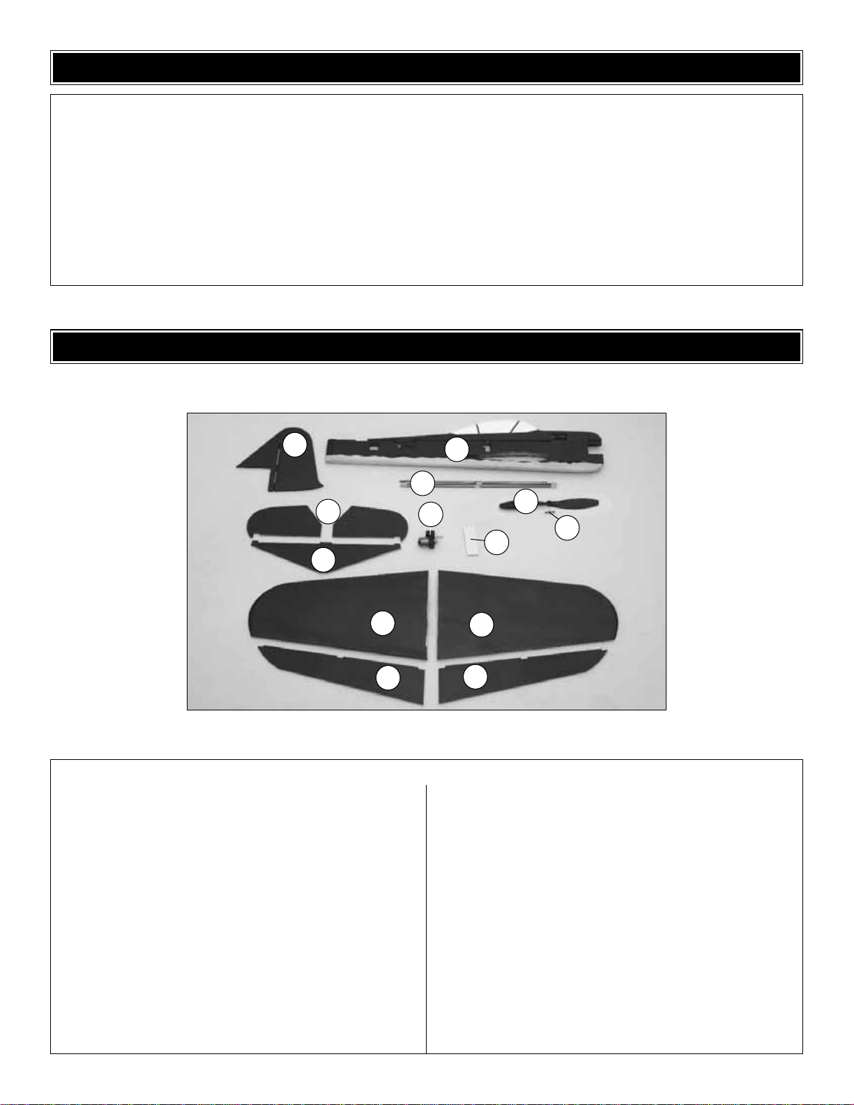
Kit Contents Photographed
1. Fin & Rudder
2. Fuselage
3. Elevator Halves (L&R)
4. Horizontal Stabilizer
5. Pushrods & Carbon Rods
6. Propeller
7. Prop Saver
8. Motor/Gearbox Assembly
9. Hook & Loop Material
10. Wing Halves (L&R)
11. Ailerons (L&R)
Kit Contents (Not Photographed)
Streamer Bag
Pushrod Bag
Hardware Bag (includes)
Single Servo Arm Extenders (2)
Double Servo Arm Extender (1)
Snap Keepers (4)
Black Control Horns w/ Backplates (4)
Kit Contents
KIT CONTENTS
1
5
4
3
10
10
11
11
6
2
7
8
9
Page 7

Note: This model is covered with a very thin layer of film
which is then painted with a special lightweight paint to
conserve weight. Avoid the use of tape to help position the
fuselage components during assembly. Also, Do Not
attempt to remove any of the trim markings as this will
damage the painted surface beneath.
Also, for simplicity, all of the carbon rods in this ARF are of
the same diameter. When identifying the rods for the
corresponding step, only the lengths are mentioned.
❏ 1. Using epoxy, join the two wing halves together,
making sure to align the root sections.
❏ 2.Epoxy the 17-3/48" [451 mm] carbon wing joiner tube
into the slot on the bottom of the wing. Make sure it is fully
seated in the slot.
❏ 3. Epoxy the foam inserts into the wing slot over the
carbon joiner. Make sure they are fully seated against the
joiner.The foam inserts may not be completely flush with the
bottom of the wing.
❏ 1. Insert the wing into the fuselage.Be sure that the wing
is centered and square by making sure all measurements
are equal as shown in the sketch.
❏ 2. Trace along the fuselage sides on the top and bottom
of the wing with a felt-tip pen or a pencil.
❏ 3. Slide the wing out just enough to see the entire area
covered by the fuselage. Remove the covering from the wing
using a hobby knife 3/32" [2 mm] inside the marks you made.
Apply a thin layer of epo xy and slide the wing into place.Use the
marks from the previous step to align the wing. Clean up any
excess glue with a paper towel. DO NOT use alcohol or any
other solvent for cleanup as the paint finish will be affected.
Join the Wing to the Fuselage
Join the Wing Halves
BUILDING INSTRUCTIONS
7
Remove shaded area
Page 8

❏ 1. Slide the stab into the slot in the rear of the fuselage.
Center it as you did with the wing. Make sure the
measurements shown in the sketches are equal. Glue the
stab in place when satisfied with the fit.
❏ 2. Locate the 13.5" [343 mm] carbon elevator rod.Insert
this rod into the preinstalled plastic bearings on the stab.DO
NOT glue in place.
❏ 3. Use foam-safe CA to glue one of the elevator halves to
the carbon elevator rod. Then glue the other elevator to the
carbon elevator rod.Be sure the two halves are even as shown.
❏ 4.Glue the fin and rudder to the fuselage with epoxy. Make
sure that the fin remains perpendicular to the stab and
centered on the fuselage.
❏❏1. Locate one of the carbon wing hinge assemblies.
One of the carbon tubes is glued to the bearings; the other
is free to rotate. Remove the loose carbon rod to prevent
accidental gluing in the next steps.
Hinge the Ailerons
Install the Tail Surfaces
8
Page 9

❏❏2.Test fit one of the wing hinges in the wing.The outer
bearing should be flush with the wing tip.When satisfied with
the fit, epoxy the hinge in place. Be careful to avoid getting
epoxy into the open bearings.
❏❏3. Slide the loose carbon rod through the bearings.
❏❏4. Test fit an aileron onto the carbon rod as shown. If
satisfied with the fit, glue the aileron to the carbon rod using
CA. DO NOT glue the aileron to the bearings.The rod must
freely rotate in the bearings, so the aileron must only be
glued to the carbon rod.
❏ 1. Remove the screws and servo arms from all of your
servos. Enlarge the hole in the center of the extender until
the head of the servo screw fits through.
❏ 2.Tr im the mounting posts off of the servo as shown in
the photo.
❏ 3.Place the original servo arm over the screw , and glue the
top of the arm to the extender with CA.Some servo arms have
small flanges projecting from the top. If your servo arms have
these flanges, sand them off before gluing.
Install the Servos
9
Page 10

❏ 4. Epoxy a servo into the bottom of the rear servo cutout
from the left side of the plane. The output shaft should be
toward the front of the fuselage. Center the servo with your
radio and screw the extended arm onto the output shaft with
the arm oriented straight up.
❏ 5. Epoxy the other tail servo into the cutout from the right
side of the plane side with the output shaft toward the front.
Center the servo with your radio and screw the extended arm
onto the output shaft with the arm oriented straight down.
❏ 6. Center your aileron servo with your radio and screw the
extended double-sided arm onto the servo.When you glue the
extended servo arm, be sure it is exactly centered as shown.
Epoxy the aileron servo into the cutout in the fuselage.
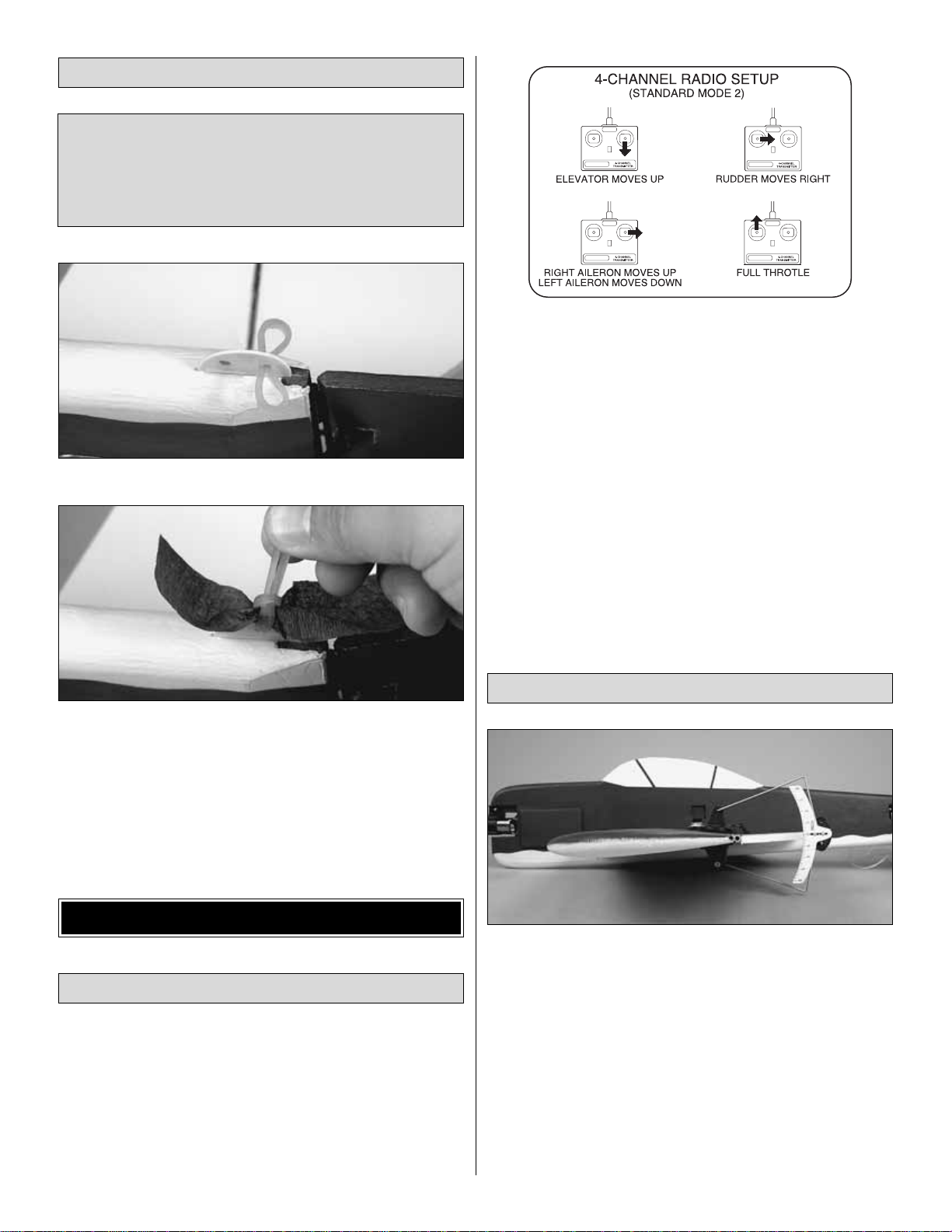
❏❏1. Locate the two 2-3/4" [70 mm] prebent aileron
pushrods. Slightly enlarge the outer hole on the aileron
servo arm. Insert the Z-bend end of the pushrods into the
outer hole on the aileron servo arm.
❏❏2.Center your aileron servo to ensure it is at neutral.Use
a small clamp or some masking tape to hold the aileron at
neutral. Align the pushrods straight back towards the ailerons.
❏❏3. Locate a black nylon control horn. Trim the small
plastic section away as shown.
❏❏4. Make a small 1/4" [6.4 mm] long cut in the aileron
behind the bearing. Insert the 90° bend of the pushrod into
the middle hole of one of the black nylon control horns.
Install the Control Horns & Pushrods
10
Page 11
❏❏5. Apply a small spot of foam-safe CA to the bottom of
the control horn and insert it into the cut in the aileron. Press a
nylon backplateon the backside of the control horn as shown.
❏❏6. Install a black nylon snap keeper onto the pushrod
at the control horn.
❏ 7. Install the rudder and elevator pushrods in the same
way as the ailerons. Use the 5-3/4" [146 mm] prebent
pushrod for the rudder and the 2-1/2" [64 mm] prebent
pushrod for the elevator.
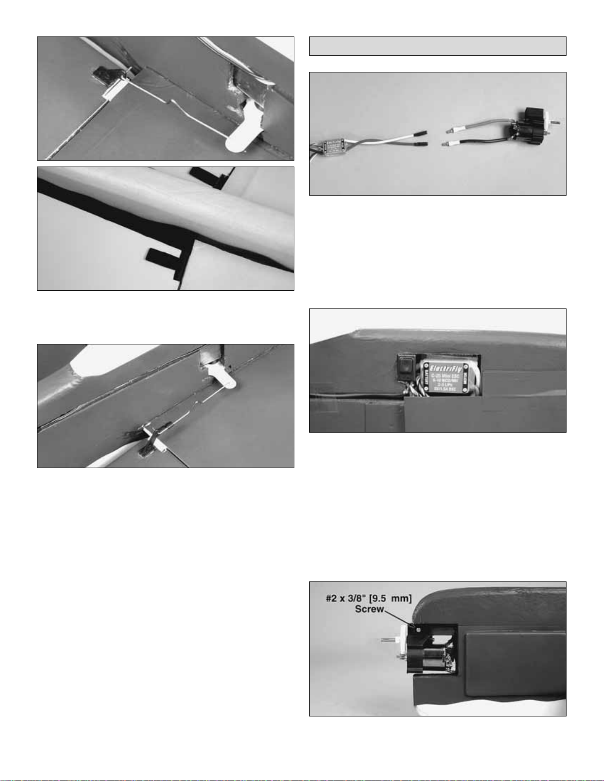
❏ 1. Connect the output wires of your ESC to the motor.
Check the direction of the motor before permanently
installing it.
❏ 2.Install the ESC as shown using a small section of hook
and loop tape. Place the hard “hook” side in the provided
cutout in the fuselage and the softer “loop” side on the back
of the ESC. If your ESC has a BEC switch, install it in the
provided cutout. For some electronic speed controls, it may
be necessary to trim the foam slightly to allow for wire
clearance and switch mounting.
❏ 3. Slide the gearbox onto the square wood stick in the
nose. Secure it with the supplied #2 x 3/8" [9.5 mm] screw.
Install the Motor & Speed Control
11
Page 12

❏ 4. Install the prop saver onto the gearbox output shaft.
The screws should seat down into the flat spots on the shaft.
Add a drop of thread-lock and be sure the screws are
tightened to prevent them from bac king out during operation.
Note: The prop saver has two diff erent diameters .Match the
size of your prop hub to the prop saver before installing the
prop to the gearbox. Attach the prop using the supplied
black O-ring.
❏ 1. Attach the receiver to the cutout in the rear of the
fuselage using a small section of the supplied hook and
loop tape. Place the rough, or “hook” side of the tape into
the cutout in the fuselage and the soft “loop”side of the tape
on the back of the receiver.
❏ 2. Connect the servos and ESC to their channels on the
receiver.You will need to use extensions to allow the aileron
servo and ESC leads to reach the receiver. Use a 6" [153
mm] extension for the aileron servo lead, and a 12" [305
mm] extension for the ESC. Route the servo leads through
the pre-cut channels in the fuselage to reach the receiver.
Hold them in place by applying clear tape (not included) over
the openings.
❏ 3. Power up your radio system and center the servos. If
necessary, adjust the center point of the control surfaces by
tightening or enlarging the V-bend in each pushrod.
❏ 4. Locate the 1" [25 mm] plastic streamer mount. Mark
the approximate midpoint of the mount.
❏ 5. Cut a 1" [25 mm] slot in the bottom of the fuselage at
the tail as shown. The exact location is not important; it
simply needs to be at the tail of the fuselage. Do not attach
the mount to the rudder control surface.
❏ 6. Test fit the mount in the groove. It should insert up to
the midpoint line. Glue in place using epoxy.
❏ 7. Drill two 1/8" [3.2 mm] holes in the mount. If not flying
combat, use the two holes to route the antenna from
the receiver.
Final Setup
12
Page 13
❏ 1. Insert a r ubber band as shown.
❏ 2. Lay one end of a colored streamer over the mount.
Insert one loop of the rubber band through the loop at the
other end. Pull it tight to hold the streamer in place.
❏ 3. Secure the antenna to the fuselage. If left to trail the
plane, it could become damaged while combating.
❏ 1. Turn on the transmitter and receiver and center the
trims. If necessary, remove the servo arms from the servos
and reposition them so they are centered. Reinstall the
screws that hold on the servo arms.
❏ 2. With the transmitter and receiver still on, check all the
control surfaces to see if they are centered.If necessary, adjust
the V-bends on the pushrods to center the control surfaces.
❏ 3. Make cer tain that the control surfaces and the motor
respond in the correct direction as shown in the diagram. If
any of the controls respond in the wrong direction, use the
servo reversing in the transmitter to reverse the servos
connected to those controls. Be certain the control surfaces
have remained centered.Adjust if necessary.
Use a Great Planes AccuThrow™(or a ruler) to accurately
measure and set the control throw of each control surface as
indicated in the chart that follows.If your radio does not ha v e
dual rates, we recommend setting the throws at the low
rate, or sport rate setting. Note: The 3D throws
recommended are extreme throws and should only be flown
by experienced pilots. They are very sensitive and could
cause the plane to seem uncontrollable to a novice pilot.
Sport rates are perfect, and recommended for, combat and
general aerobatic flight.
Note: The throws are measured at the widest par t of the
elevators, rudder and ailerons.
Set the Control Throws
Check the Control Directions
GET THE MODEL READY TO FLY
The EP Zero ARF was designed with the intention that two
or more of these easily built, fun to fly models could be
outfitted with streamers and used for combat.If you intend to
fly combat with this model, you will need to attach the
optional streamer mount using the instructions below.
Optional Combat Setup
13
Page 14

At this stage the model should be in ready-to-fly condition
with all of the systems in place.
❏ 1. Use a felt-tip pen or 1/8" [3 mm]-wide tape to accurately
mark the C.G. on the top of the wing on both sides of the
fuselage. The C.G. is located 3-1/4" [83 mm] back from the
leading edge of the wing.
❏ 2. With the wing attached to the fuselage and all parts of
the model installed (ready to fly), place the model upsidedown on a Great Planes CG Machine, or lift it upside-down
at the balance point you marked.
❏ 3. If the tail drops, the model is “tail heavy” and weight
must be added to the nose to balance.If the nose drops, the
model is “nose heavy” and weight must be added to the tail
to balance.If additional weight is required, use Great Planes
(GPMQ4485) “stick-on” lead. A good place to add stick-on
nose weight is to the bottom of the fuse at the nose (don’t
attach weight to the battery box–it is not intended to support
weight). Begin by placing incrementally increasing amounts
of weight on the bottom of the fuse under the nose until the
model balances. Once you have determined the amount of
weight required, it can be permanently attached. If required,
tail weight may be added in the same manner.
❏ 4. IMPORTANT: If you found it necessary to add any
weight, recheck the C.G.after the weight has been installed.
❏ 1. With the wing level, have an assistant help you lift the
model by the motor propeller shaft and the bottom of the
fuse under the TE of the fin.Do this several times.
❏ 2.If one wing always drops when you lift the model, it means
that side is heavy. Balance the airplane by adding weight to the
other wing tip. An airplane that has been laterally balanced
will track better in loops and other maneuvers.
Balance the Model Laterally
This is where your model should balance for the first
flights. Later, you may wish to experiment by shifting the
C.G. up to 1/4" [6.4 mm] forward or 3/4" [19 mm] back to
change the flying characteristics. Moving the C.G.forward
may improve the smoothness and stability, but the model
may then require more speed for takeoff and be more
difficult to slow for landing.Moving the C.G.aft makes the
model more maneuverable, but could also cause it to
become too difficult to control. In any case, start at the
recommended balance point and do not at any time
balance the model outside the specified range.
More than any other factor, the C.G. (balance point) can
have the greatest effect on how a model flies, and may
determine whether or not your first flight will be
successful. If you value this model and wish to enjoy it for
many flights, DO NOT OVERLOOK THIS IMPORTANT
PROCEDURE. A model that is not properly balanced will
be unstable and possibly unflyable.
Balance the Model (C.G.)
IMPORTANT: The EP Zero ARF has been extensively
flown and tested to arrive at the throws at which it flies
best. Flying your model at these throws will provide you
with the greatest chance for successful first flights.If , after
you have become accustomed to the way the EP Zero
ARF flies, you would like to change the throws to suit your
taste, that is fine. However, too much control throw could
make the model difficult to control, so remember, “More is
not always better.”
These are the recommended control surface throws:
High Rate/3D Rate Low Rate/Sport Rate
ELEVATOR: 3-1/2" [89 mm] up 1-1/2" [38 mm] up
3-1/2" [89 mm] down 1-1/2" [38 mm] down
RUDDER: 3-1/2" [89 mm] right 2" [51 mm] right
3-1/2" [89 mm] left 2" [51 mm] left
AILERONS: 3" [76 mm] up 1-5/8" [41 mm] up
3" [76 mm] down 1-5/8" [41 mm] down
14
3-1/4" [83 mm]
Page 15

No matter if you fly at an AMA sanctioned R/C club site or if you
fly somewhere on your own, y ou should always ha ve your name,
address, telephone number and AMA number on or inside your
model. It is required at all AMA R/C club flying sites and AMA
sanctioned flying events .Fill out the identification tag on page 17
and place it on or inside your model.
Follow the battery charging instructions that came with your
radio control system to charge the batteries. You should
always charge your transmitter and receiver batteries the
night before you go flying, and at other times as
recommended by the radio manufacturer.
Carefully balance your propeller and spare propellers before
you fly. An unbalanced prop can be the single most
significant cause of vibration that can damage your model.
Not only will motor mounting screws and bolts loosen,
possibly with disastrous effect, but vibration may also
damage your radio receiver and battery.When balancing the
propeller that came with your Fun Force ARF, add tape to
the light side of the propeller.Do not sha v e material aw ay as
is done with traditional propellers.
We use a Top Flite Precision Magnetic Prop Balancer
™
(TOPQ5700) in the workshop and keep a Great Planes
Fingertip Prop Balancer (GPMQ5000) in our flight box.
Check the motor operation by running it to full power and
back down. It should respond quickly and smoothly through
the full range of throttle travel.After you run the motor on the
model, inspect the model closely to make sure all screws
remained tight, the hinges are secure, the prop is secure
and all pushrods and connectors are secure.
It is important to ground check the operational range of your
radio before the first flight of the day. With the transmitter
antenna collapsed and the receiver and transmitter on, you
should be able to walk at least 100 feet [30.5 m] away from the
model and still have control.Ha v e an assistant hold your model
and, while you work the controls, tell you what the control
surfaces are doing.Repeat this test with the motor running at
various speeds with an assistant holding the model, using hand
signals to show you what is happening. If the control surfaces
do not respond correctly, do not fly! Find and correct the
problem first.Look for loose servo connections or brok en wires,
corroded wires on old servo connectors, poor solder joints in
your battery pack or a defective cell, or a damaged receiver
crystal from a previous crash.
Get help from an experienced pilot when learning to
operate motors.
Use safety glasses when starting or running motors.
Do not run the motor in an area of loose gravel or sand;the
propeller may throw such material in your face or eyes.
Keep your f ace and body as well as all spectators a wa y from the
plane of rotation of the propeller as you start and run the motor.
Keep these items away from the prop: loose clothing, shirt
sleeves, ties, scarves, long hair or loose objects such as
pencils or screwdrivers that may fall out of shirt or jacket
pockets into the prop.
The motor gets hot! Do not touch it during or right
after operation.
Do not throw anything into the propeller of a running motor.
Failure to follow these safety precautions may result
in severe injury to yourself and others.
MOTOR SAFETY PRECAUTIONS
Range Check
Ground Check
Balance the Propellers
CAUTION: Unless the instructions that came with your
radio system state differently, the initial charge on new
transmitter and receiver batteries should be done for 15
hours using the slow-charger that came with the radio
system.This will “condition” the batteries so that the next
charge may be done using the fast-charger of y our choice.
If the initial charge is done with a fast-charger, the
batteries may not reach their full capacity and you may be
flying with batteries that are only partially charged.
Charge the Batteries
Identify Y our Model
PREFLIGHT
15
Page 16

Read and abide by the following excerpts from the Academy
of Model Aeronautics Safety Code.For the complete Safety
Code refer to
Model Aviation
magazine, the AMA web site or
the Code that came with your AMA license.
1) I will not fly my model aircraft in sanctioned events, air
shows, or model flying demonstrations until it has been
proven to be airworthy by having been previously,
successfully flight tested.
2) I will not fly my model aircraft higher than approximately
400 feet within 3 miles of an airport without notifying the
airport operator .I will giv e right-of-wa y and av oid flying in the
proximity of full-scale aircraft.Where necessary, an observer
shall be utilized to supervise flying to avoid having models
fly in the proximity of full-scale aircraft.
3) Where established, I will abide by the safety rules for the
flying site I use, and I will not willfully and deliberately fly my
models in a careless, reckless and/or dangerous manner.
5) I will not fly my model unless it is identified with my name
and address or AMA number, on or in the model.Note:This
does not apply to models while being flown indoors.
7) I will not operate models with pyrotechnics (any device
that explodes, burns, or propels a projectile of any kind).
1) I will have completed a successful radio equipment ground
check before the first flight of a new or repaired model.
2) I will not fly my model aircraft in the presence of
spectators until I become a qualified flier, unless assisted b y
an experienced helper.
3) At all flying sites a straight or curved line(s) must be
established in front of which all flying takes place with the
other side for spectators.Only personnel involved with flying
the aircraft are allowed at or in the front of the flight line.
Intentional flying behind the flight line is prohibited.
4) I will operate my model using only radio control frequencies
currently allowed by the Federal Communications Commission.
5) I will not knowingly operate my model within three
miles of any pre-existing flying site except in
accordance with the frequency sharing agreement
listed [in the complete AMA Safety Code].
9) Under no circumstances may a pilot or other person touch
a powered model in flight; nor should any part of the
model other than the landing gear, intentionally touch
the ground, except while landing.
❏ 1. Check the C.G. according to the measurements
provided in the manual.
❏ 2. Be certain the battery and receiver are securely
mounted in the fuse.
❏ 3. Extend your receiver antenna. Be careful to keep
pressure off the solder joint inside the receiver.
❏ 4. Balance your model
laterally
as explained in
the instructions.
❏ 5. Make sure all hinges are securely glued in place.
❏ 6. Confirm that all controls operate in the correct direction
and the throws are set up according to the manual.
❏ 7. Make sure any servo extension cords you may have
used do not interfere with other systems (servo arms,
pushrods, etc.).
❏ 8. Balance your propeller (and spare propellers).
❏ 9. Tighten the prop saver screws.
❏ 10.Place your name, address, AMA number and
telephone number on your model.
❏ 11. Cycle your battery pack (if necessary) and make sure
it is fully charged.
❏ 12. If you wish to photograph your model, do so before
your first flight.
❏ 13. Range check your radio when you get to the flying field.
The EP Zero ARF is a great-flying model that flies smoothly
and predictably. The EP Zero ARF does not, however,
possess the self-recovery characteristics of a primary R/C
trainer and should be flown only by experienced R/C pilots.
FLYING
During the last few moments of preparation your mind may
be elsewhere anticipating the excitement of the first flight.
Because of this, you may be more likely to overlook certain
checks and procedures that should be performed before the
model is flown.To help avoid this, a
check list
is provided to
make sure these important areas are not overlooked. Many
are covered in the instruction manual, so where appropriate
refer to the manual for complete instructions. Be sure to
check the items off as they are completed.
CHECK LIST
Radio Control
General
AMA SAFETY CODE (excerpts)
16
Page 17

For the first flight, it is a good idea to have a friend launch
the airplane for you.This allows you to keep your hands on
the radio sticks and correct any trim problems that are
present. Have your friend hold the EP Zero ARF by the
canopy. Throttle up to full power, and have your friend give
the plane a gentle underhanded toss at about a 30° angle
upward. Since the EP Zero ARF has a very high thrust to
weight ratio, the plane will accelerate to flying speed almost
instantly.Climb to a comfortable altitude and throttle back to
a lower power setting. This plane flies great at about halfthrottle when in standard forward flight.
For reassurance and to keep an eye on other traffic, it is a
good idea to have an assistant on the flight line with you.Tell
him to remind you to throttle back once the plane gets to a
comfortable altitude.While full throttle is usually desirable for
takeoff, most models fly more smoothly at reduced speeds.
Take it easy with the EP Zero ARF for the first few flights,
gradually getting acquainted with it as you gain confidence.
Adjust the trims to maintain straight and level flight. After
flying around for a while, and while still at a saf e altitude with
plenty of battery power, practice slow flight and execute
practice landing approaches by reducing the throttle to see
how the model handles at slower speeds.Add power to see
how she climbs as well. Continue to fly around, executing
various maneuvers and making mental notes (or having
your assistant write them down) of what trim or C.G.
changes may be required to fine tune the model so it flies
the way you like. Mind your battery power, but use this first
flight to become familiar with your model before landing.
To initiate a landing approach, lower the throttle while on the
downwind leg. Allow the nose of the model to pitch
downward to gradually bleed off altitude. Continue to lose
altitude, but maintain airspeed by k eeping the nose down as
you turn onto the crosswind leg.Make your final turn toward
the landing area (into the wind), keeping the nose down to
maintain airspeed and control. Level the attitude when the
model reaches an altitude of about 10 feet, modulating the
throttle as necessary to maintain your glide path and
airspeed. If you are going to overshoot, smoothly advance
the throttle (always ready on the right rudder to counteract
torque) and climb out to make another attempt.When y ou’re
ready to make your landing and the model is a foot or so off
the deck, cut your throttle and smoothly increase up ele v ator
until it gently touches down on its belly. Make sure that you
cut your power completely before touchdown, or gearbox
damage may result.
One final note about flying your model: Have a goal or flight
plan in mind for every flight. This can be learning a new
maneuver(s), improving a maneuver(s) you already know, or
learning how the model behaves in certain conditions (such as
on high or low rates). This is not necessarily to improve your
skills
(though it is never a bad idea!)
, but more importantly so
you do not surprise yourself by impulsively attempting a
maneuver and suddenly finding that you’ve run out of time,
altitude or airspeed.Every maneuver should be deliberate, not
impulsive.F or e xample, if y ou’ re going to do a loop , chec k y our
altitude, mind the wind direction (anticipating rudder
corrections that will be required to maintain heading),
remember to throttle back at the top, and mak e certain you are
on the desired rates (high/low rates). A flight plan greatly
reduces the chances of crashing your model just because of
poor planning and impulsive moves.
Have a ball! But always
stay in control and fly in a safe manner.
GOOD LUCK AND GREAT FLYING!
Fill in and place on or inside your model.
Landing
Flight
Launch
CAUTION (THIS APPLIES TO ALL
R/C AIRPLANES): If,
while flying, you notice an alarming or unusual sound
such as a low-pitched “buzz,” this may indicate control
surface
flutter
.Flutter occurs when a control surface (such
as an aileron or elevator) or a flying surface (such as a
wing or stab) rapidly vibrates up and down (thus causing
the noise). In extreme cases, if not detected immediately,
flutter can actually cause the control surface to detach or
the flying surface to fail, thus causing loss of control
followed by an impending crash. The best thing to do
when flutter is detected is to slow the model immediately
by reducing power, then land as soon as safely possible.
Identify which surface fluttered (so the problem may be
resolved) by checking all the servo grommets for
deterioration or signs of vibration. Make certain all
pushrod linkages are secure and free of play. If it fluttered
once, under similar circumstances it will probably flutter
again unless the problem is fixed.Some things which can
cause flutter are; Excessive hinge gap; Not mounting
control horns solidly; Poor fit of clevis pin in horn; Sideplay of wire pushrods caused by large bends; Excessive
free play in servo gears; Insecure servo mounting; and
one of the most prevalent causes of flutter;Flying an overpowered model at excessive speeds.
17
Page 18
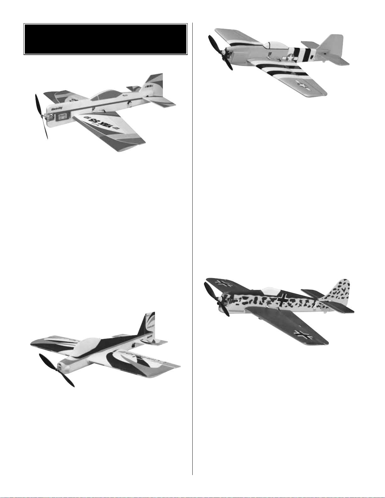
Great Planes ElectriFly Yak 55 EP 3D ARF
You don’t need expensive brushless motor systems for 3D
electric aerobatics.The Yak’s enormous control surfaces and
full flying stabilizer offer impressive maneuverability and
hovering potential with the powerful, included 280-size
brushed motor and 5:1 gearbox. Its low parts count and
easy final assembly will have this aerobat flight-ready in just
2-3 hours. The durable, lightweight EPS foam airframe
features a high-vis, preapplied trim scheme. An included
“prop saver” allows the prop to deflect back upon landing,
and is compatible with APC or GWS prop hubs.GPMA1190
Great Planes ElectriFly U-Can-Do 3D EP ARF
It’s a park flyer, ARF and 3D trainer all in one! Less than a
yard across the wing tips and weighing just 15 ounces, the
U-Can-Do 3D EP is small enough to fly at nearby parks and
fields. And its unique FlightFlex airframe not only simplifies
assembly to just 2 to 4 easy hours...it also results in virtual
indestructibility! Touch down hard – it’ll bounce and bend,
but not break.With the included ball bearing 280 motor, 5:1
gearbox and prop, it flies like a champ, performing hovers,
harriers and any other 3D stunt you care to name with
authority. GPMA1275
ElectriFly Fun Force P-51D Mustang EP Sport Combat ARF
It’s fun for sport, fun for combat – and easily affordable
whichever way you go! The P-51D Mustang’s 33.5"
wingspan makes any open area a potential flying field.
Minimal assembly and a factory-applied, semi-scale trim
scheme enable you to get to the field fast. Carbon-fiber
tubes and EPS foam construction enable your plane to last
and last. If you’re content with slow and steady flight, it’s
ready to please. But with its light weight, symmetrical airfoil
and large control surfaces, this favorite American warbird is
also capable of sudden right-angle turns and table-turning
moves in combat.Attach the included streamers, and you’re
ready for a dogfight! Includes complete hardware and a
motor package that features a Speed Force 370 BB motor,
5:1 gearbox, prop and prop saver. GPMA1192
ElectriFly Fun Force FW-190 Focke Wulf EP Sport
Combat ARF
It’s fun for sport, fun for combat – and easily affordable
whichever way you go! The FW-190 Focke Wulf’s 33.5"
wingspan makes any open area a potential flying field.
Minimal assembly and a factory-applied, semi-scale trim
scheme enable you to get to the field fast. Carbon-fiber
tubes and EPS foam construction enable your plane to last
and last. If you’re content with slow and steady flight, it’s
ready to please. But with its light weight, symmetrical airfoil
and large control surfaces, this f eared German fighter is also
capable of sudden right-angle turns and table-turning moves
in combat. Attach the included streamers, and you’re ready
for a dogfight! Includes complete hardware and a motor
package that features a Speed Force 370 BB motor, 5:1
gearbox, prop and prop saver.GPMA1193
OTHER ITEMS AVAILABLE
FROM GREAT PLANES
18
Page 19

ElectriFly™by Great Planes Triton™Peak Charger
Imagine a charger so versatile it can be used with lithium-ion
and lead-acid batteries as effectively as NiCd and NiMH
cells. A unit that can peak charge tiny park flyer packs and
24V car batteries alike.A charger that can discharge as well
as charge, cycle packs from 1 to 10 times automatically,
memorize peak and average battery voltages for each cycle
– and constantly display battery capacity, voltage, current
and time as each cycle progresses. Then, imagine that the
charger, which can do all this, is about the size of a thick
paperback book, and weighs just over a pound. The
advanced computer technology in the Triton Peak Charger
makes it possible to accomplish all this and more, through
controls and menus so simple that programming is a breeze.
For more information, log on at www.electrifly.com – and
be amazed. 1-year warranty. GPMM3150
Great Planes ElectriFly PolyCharge Charger
Simple to set up and use, the PolyCharge is perf ect f or 1-3 cell
LiPo power packs.It’s about the size of a business card – and
weighs just over 4 ounces! PolyCharge automatically starts
charging when the pack is connected, and automatically stops
at full charge. Adjusting the charge rate to capacity takes only
a moment and a touch on the selector switch. Choose from
250mA, 500mA or 1,000mA rates. A buzzer and blue LED
indicate start/stop charge; high/low voltage input; reverse
polarity (output), and loose/broken pack connection. Includes
alligator clips on a 30" lead for input and a standard red 2-pin
connector on output. GPMM3010
Great Planes ElectriFly 1500mAh Lithium-Pol ymer Battery
Lithium-Polymer (LiPo) cells provide three times the voltage
of NiCd and NiMH cells – at less than half the weight!
Exclusive SafeCharge
™
circuitry protects ElectriFly LiPo
packs by preventing any cell from overcharging.This 11.1V,
3 series pack includes a 2-pin red charge connector and
separate discharge connector.GPMP0831
Futaba 4EXA 4-Channel FM Computer Radio
If you’re a new pilot, the 4EXA is a good deal – and a good
deal for the future, too. You’ll enjoy the performance edge
and ease of computer design, beginning with simple
programming:navigate menus and select y our set-ups using
just two keys (Mode and Select), and then lock-in those
digitally accurate settings with the Data Input Lever.You can
save up to four set-ups in the 4EXA’s memory...a big timesaver as you add more planes to your personal hangar.
You’ll also enjoy the 4EXA’s versatility. With more channels
than 2- or 3-channel systems and more features than most
“start up” 4-channel radios, the 4EXA “grows” with you as
your skills and experience increase. EPA for servos,
automatic trim memory, exponential, wing mixing for V-tail
and elevon – the 4EXA has them. You’ll be able to
experiment with new types of flying, with the familiar layout
and feel of a system you already know.
Save yourself the cost and inconvenience of “trading up,”
with a radio that will be as useful tomorrow as it is today.The
4EXA includes an R124DF receiver, three S3108 servos
and 600mAh Tx and Rx NiCds.72MHz. FUTK41**
19
Page 20

BUILDING NOTES
Kit Purchased Date: _______________________
Where Purchased: _________________________
Date Construction Started: __________________
Date Construction Finished: _________________
Finished Weight: __________________________
Date of First Flight: ________________________
FLIGHT LOG
 Loading...