

Page 1
Installationand
Operation
EmergencyPowerOffSystem
Page 2

LegalDisclaimer
TheinformationpresentedinthismanualisnotwarrantedbytheSchneiderElectricIT
Corporationtobeauthoritative,errorfree,orcomplete.Thispublicationisnotmeanttobea
substituteforadetailedoperationalandsitespecicdevelopmentplan.Therefore,Schneider
ElectricITCorporationassumesnoliabilityfordamages,violationsofcodes,improper
installation,systemfailures,oranyotherproblemsthatcouldarisebasedontheuseofthis
Publication.
TheinformationcontainedinthisPublicationisprovidedasisandhasbeenpreparedsolely
forthepurposeofevaluatingdatacenterdesignandconstruction.ThisPublicationhasbeen
compiledingoodfaithbySchneiderElectricITCorporation.However,nopresentationor
warranty,eitherexpressorimplied,ismadeastothecompletenessoraccuracyoftheinformation
thisPublicationcontains.
INNOEVENTSHALLSCHNEIDERELECTRICITCORPORA TIONBELIABLE
FORANYDIRECT,INDIRECT,CONSEQUENTIAL,PUNITIVE,SPECIAL,OR
INCIDENTALDAMAGES(INCLUDING,WITHOUTLIMITA TION,DAMAGESFOR
LOSSOFBUSINESS,CONTRACT,REVENUE,DATA,INFORMATION,ORBUSINESS
INTERRUPTION)RESULTINGFROM,ARISINGOUTOF ,ORINCONNECTIONWITH
THEUSEOF,ORINABILITYTOUSETHISPUBLICA TIONORTHECONTENT ,EVEN
IFSCHNEIDERELECTRICITCORPORATIONHASBEENEXPRESSL YADVISEDOF
THEPOSSIBILITYOFSUCHDAMAGES.SCHNEIDERELECTRICITCORPORATION
RESERVESTHERIGHTTOMAKECHANGESORUPDA TESWITHRESPECTTOOR
INTHECONTENTOFTHEPUBLICA TIONORTHEFORMATTHEREOFATANYTIME
WITHOUTNOTICE.
Copyright,intellectual,andallotherproprietaryrightsofthecontent(includingbutnotlimitedto
software,audio,video,text,andphotographs)restswithSchneiderElectricITCorporationorits
licensors.Allrightsinthecontentnotexpresslygrantedhereinarereserved.Norightsofany
kindarelicensedorassignedorshallotherwisepasstopersonsaccessingthisinformation.
ThisPublicationshallnotbeforresaleinwholeorinpart.
Page 3

TableofContents
IMPORTANTSAFETYINSTRUCTIONSSAVETHESE
INSTRUCTIONS...............................................................................................................1
SafetyInstructionsforNorthAmerica...................................................................1
SafetyInstructionsforEurope,MiddleEast,andAfrica...................................2
Specications...................................................................................................................3
Overview..............................................................................................................................4
EmergencyPowerOffSystem..................................................................................4
EPOBoxComponents................................................................................................4
Installation..........................................................................................................................6
PreparetheEPO...........................................................................................................6
MounttheEPO(RunningConduitsorCablesAlongtheWall).......................6
MounttheEPO(runningconduitsorcablesbehindthewall).........................7
ConnectDevicestotheEPOBox............................................................................9
MountAdditionalEPOBoxes...................................................................................10
CascadeMultipleEPOBoxes...................................................................................10
CascadetheAPCDeviceswithCAT-5Cables............................................................11
CascadetheAuxiliaryDevicewithWirePairs...........................................................12
DirectWiringAlternative............................................................................................12
VerifyConnectionsateachEPOBox.....................................................................12
Operation............................................................................................................................14
EngagetheSystem......................................................................................................14
ResettheEPOSystem................................................................................................14
ResettheEquipment...................................................................................................15
WiringDiagram................................................................................................................16
990–1611C-001
EmergencyPowerOffSystemInstallationandOperation
i
Page 4

ii
EmergencyPowerOffSystemInstallationandOperation
990–1611C-001
Page 5
IMPORTANTSAFETYINSTRUCTIONS SAVETHESEINSTRUCTIONS
Thismanualcontainsimportantinstructionsthatshouldbefollowedduringinstallation,operation,and
maintenanceoftheEPOsystem.
SafetyInstructionsforNorthAmerica
WARNING:Onlycertiedelectriciansmayinstallthesystemandthewiringtothe
productsITcontrols.
WARNING:Assemblyhasnotbeenevaluatedforemergencylifecriticalapplications,
butisintendedforemergencyequipmentpoweroff.
Note:WiringfromthesystemtotheproductsITcontrolscaneitherbeinstalledinconduits
orinstalledwithoutconduitsifthewiresareinaccordancewithArticle725oftheNational
ElectricalCode(NFPA70)andSection16oftheCanadianElectricalCode(C22.1).
Caution:OnlyClass2circuitsrated30Vorlesscanbeconnectedtoterminals1–8.Class2
circuitsaredenedinArticle725oftheNationalElectricalCode(NFP A70)andSection16
oftheCanadianElectricalCode(C22.1).AClass2circuitisasourcehavinglimitedvoltage
andenergycapacityasfollows:
A.IfanInherentlyLimitedPowerSource,voltageislimitedto30V ACor30VDC,and
energyislimitedto8A.
B.IfnotanInherentlyLimitedPowerSource,voltageislimitedto30V ACor30VDC,
energyislimitedto250V A,andcurrentislimitedto1000/Vmax.Thefuseislimited
to5Aifmaximumvoltageis20V ,or100/Vmaxifvoltageisgreaterthan20V
butlessthan30V .
990–1611C-001
EmergencyPowerOffSystemInstallationandOperation
1
Page 6

SafetyInstructionsforEurope,MiddleEast,andAfrica
WARNING:Onlycertiedelectriciansmayinstallthesystemandthewiringtothe
productsITcontrols.
WARNING:Assemblyhasnotbeenevaluatedforemergencylifecriticalapplications,
butisintendedforemergencyequipmentpoweroff.
Note:WiringfromthesystemtotheproductsITcontrolscaneitherbeinstalledinconduits
orinstalledwithoutconduitsifthewiresareinaccordancewithIEC/EN60364-5-52or
equivalentlocalelectriccode.
Caution:EPOcanbeachievedwitheitheracontactclosureorapplicationofanexternal
24VACor24VDCfromaSELVorPELVsource.Itisimportanttonotethathazardous
voltagefromthemainsvoltagemustbeisolatedfromthecontactclosureor24VAC,24
VDC.TheEPOcircuitcontactclosure,the24V AC,orthe24VDCareconsideredSELV
circuitsasdenedinEN60950“SafetyofInformationTechnologyEquipment”orPEL V
circuitsasdenedinIEC60364-4-41“ElectricalInstallationsofBuildingsProtectionfor
Safety—ProtectionAgainstElectricShock.”SEL VisanabbreviationforSafetyExtraLow
V oltage.PEL VisanabbreviationforProtectiveExtraLowV oltage.SELVandPEL V
circuitsareisolatedfromthemainsthroughasafetyisolatingtransformer,anddesignedso
thatunderisolatedfromthemainsthroughasafetyisolatingtransformer,anddesignedso
thatundernormalconditionsthevoltageislimitedto42.4Vpeakor60VDC.
2
EmergencyPowerOffSystemInstallationandOperation
990–1611C-001
Page 7

Specications
Electrical
Input/Output
V oltage
Current1Aat24VDC
Frequency
Circuits(qty)
Contactstate
Physical
Dimensions(W×L×D)
EPObox226×251×66mm(8.9×9.9×2.6in)
Shipping305×305×140mm(12×12×5.5in)
Weight
EPObox2.9kg(6.4lb)
Shipping3.1kg(6.9lb)
24VDC
48VDC/240VAC(Externalcircuit)
1Aat48VDC(Externalcircuit)
50/60Hz
9
NormallyOpen(NO)
MountingSurfacemount
ConnectionRemovablepanelsinrear,13mm(½in)and6mm(¾in)knockoutsontopand
bottom
PushbuttonStandard,22mmmetallicbody;40mmmushroomhead;Push/pull
Wireconnections0.10to0.75mm²(24to18AWG)wiregroundstudfor#8ringlug
Environmental
Temperature
Humidity5to95%,non-condensing
Elevation3000m(10000ft)
–5to45°C(23to113°F)
Compliance
StandardsNFPA70,NFP A75,NECArticle645,29CFR1910.36,29CFR1910.306
Approvals
UL,C-UL,CE
990–1611C-001
EmergencyPowerOffSystemInstallationandOperation
3
Page 8
Overview
5
6
7
8
9
:
=
;
<
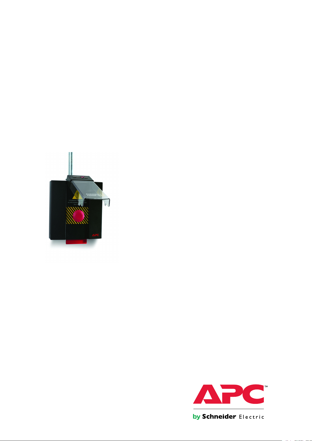
EmergencyPowerOffSystem
TheEmergencyPowerOff(EPO)Systemconsistsofoneormorewall-mounted,push-buttonEPOboxes.
EachEPOboxprovidesasinglepointofequipmentshutdownforuptoeightAPCdevicesandone
third-partydevice(suchasanupstreambreaker),usingNormallyOpen(NO)contactclosureconnections.
AnEPOboxcanbecascadedwithotherEPOboxestosupportmultiplepointsofequipmentshutdown.
Note:AlthoughtheEPOisdesignedspecicallyforAPCproducts,thesystemcanbeused
fortrippinganydevicesthatfallwithinitsparameters.See“Specications“toconrm
properapplication.InstalltheEPOaccordingtotheinstructionsinthismanual.
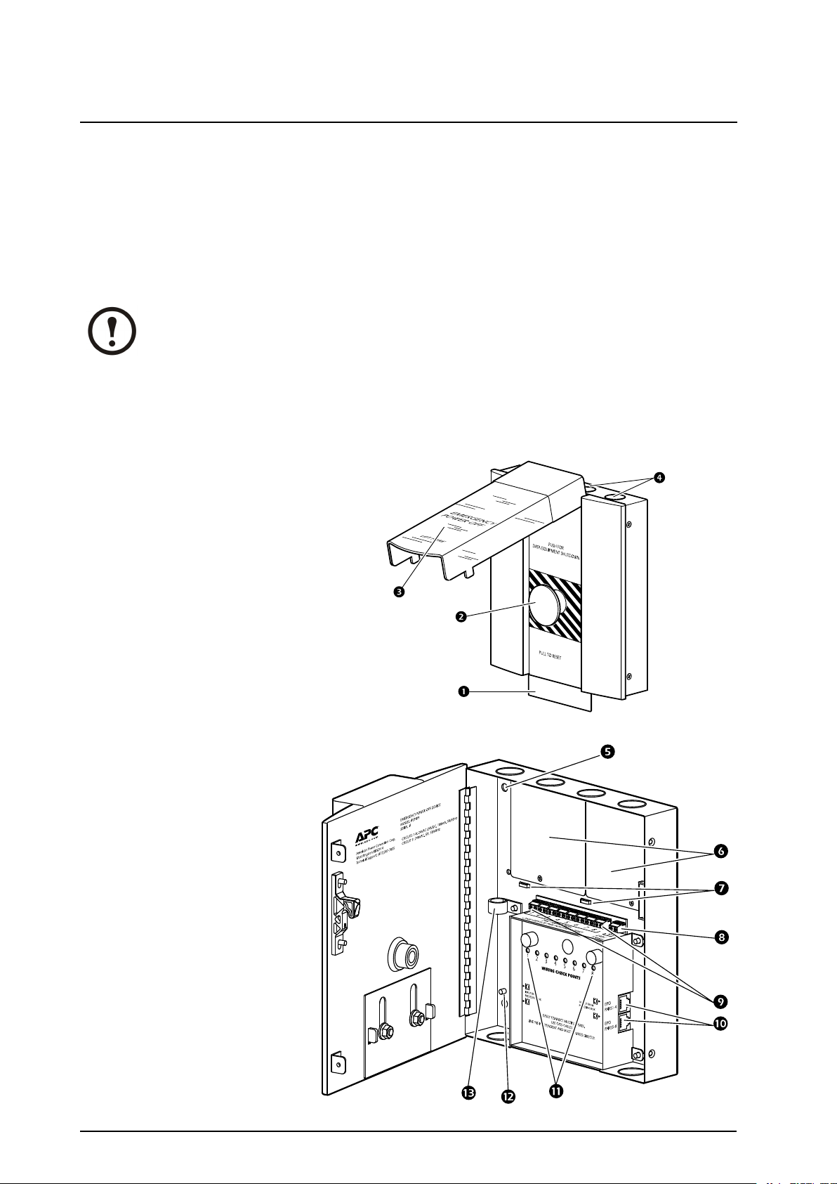
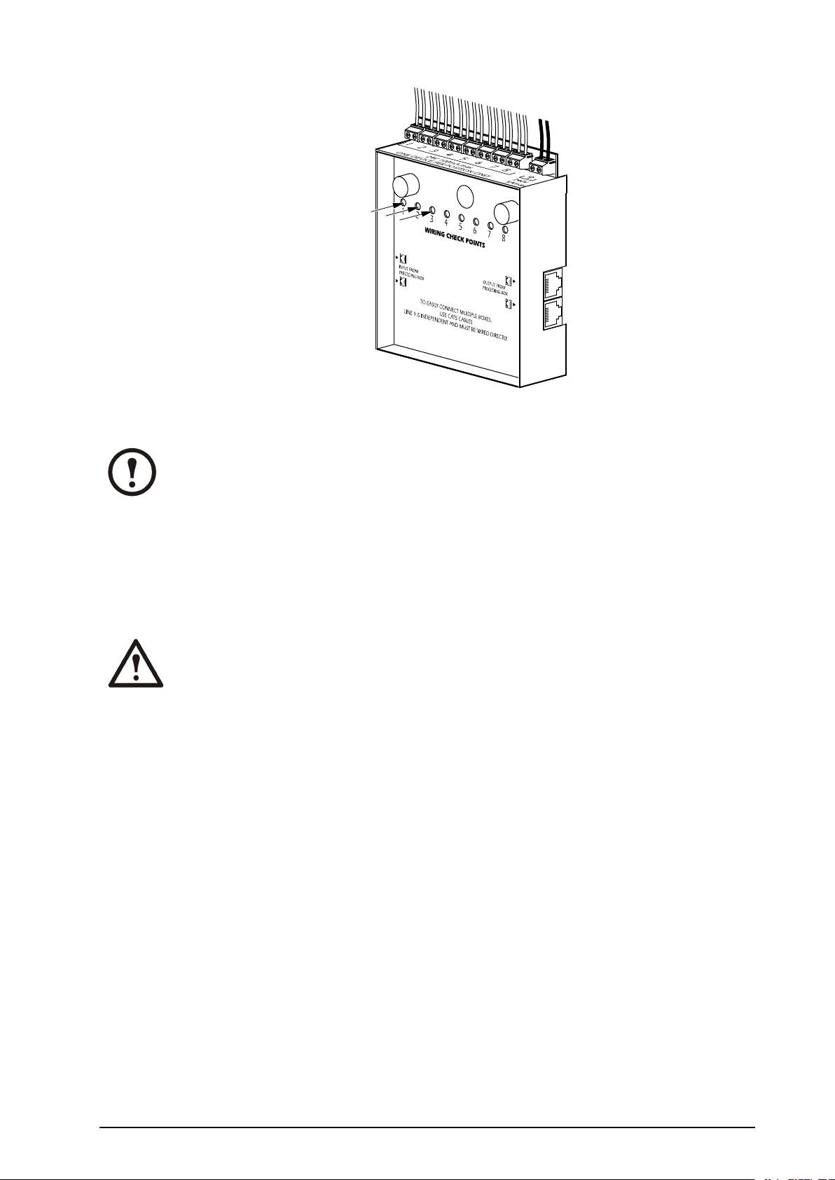
EPOBoxComponents
1
2
3
4
5
6
7
8
9
Flag
Button
Shield
Knockouts
Mountingholes
Blankingpanels
Wireanchors
Auxiliarydevice
terminal
Deviceterminalblock
10
11
12
13
4
Cascadingjacks
Wiringcheckpoints
Groundstud
Cableclamps
EmergencyPowerOffSystemInstallationandOperation
990–1611C-001
Page 9

Note:
Wiring,conduits,andmountinghardwarearenotprovided.
990–1611C-001
EmergencyPowerOffSystemInstallationandOperation
5
Page 10

Installation
PreparetheEPO
1.OpentheEPOSystemboxbyremovingthe
screwsontheside.Keepthescrewsforuse
afterthesystemisinstalled.Theboxwillnot
closesecurelywithoutthescrewsinplace.
2.Mountthesysteminareadily-accessiblearea,
onawallneartheprincipalentrancedoors,
accordingtoNECArticles645.10and645.11,
IEC/EN60354-5-537,orequivalentlocal
regulation.Therearetwodifferentprocedures
formountingthesystem,dependingon
whetheryouarerunningconduits(orcables)
alongthewallorbehindthewall.
Note:Ifnotusingconduits,runthecablesfromtheconnecteddevicesorthecascadedEPO
boxesdirectlytotheEPOusingshieldingtroughsandcableladders.
MounttheEPO(RunningConduitsorCablesAlong theWall)
1.Fastenfour6.35mm(¼in)screwsthroughthe
fourmountingholesateachcorneroftheEPO
boxandintothewall.
2.Runtheconduits(orcables)fortheconnected
devicestotheEPObox.Ifusingconduits,
itwillcontainallwiringfromtheconnected
devicesandallcascadingcables.The
knockoutsinthetopandbottomoftheEPO
boxaccept13mm(½in)and19mm(¾in)
conduitsorclustersofcables.Removethe
knockoutsrequiredforinstallation.
Note:Whenplanningconduits
requirements,considerthattwo
cascadingcableswilltin13mm
(½in)conduitsandfourcascading
cableswilltin19mm(¾in)
conduits.See“CascadeMultiple
EPOBoxes“formoreinformation.
6
EmergencyPowerOffSystemInstallationandOperation
990–1611C-001
Page 11

3.Installanappropriatettingwithalock-nut
One120mm(4in)squarejunctionbox
Two120mm(4in)squarejunctionboxes
Oneswitchboxupto4-ganginsize
foreachknockoutused.
4.Connectconduitstothettings.
Note:Ifnotusingconduits,runthe
cablesthroughtheknockoutdirectly .
MounttheEPO(runningconduitsorcablesbehind thewall)
1.Installajunctionboxoraswitchboxbehind
thewall.TheEPOboxwillfastendirectlyto
thebox.Useoneoftheoptionsabove.
990–1611C-001
EmergencyPowerOffSystemInstallationandOperation
7
Page 12

2.Runtheconduits(orcables)fromthe
connecteddevicestothejunctionorswitch
box.Ifusingconduits,itwillcontainallwiring
fromtheconnecteddevicesandallcascading
cables.Removetheknockoutsrequiredfor
installation.
Note:Whenplanningconduit
requirements,considerthattwo
cascadingcableswilltin13mm
(½in)conduitsandfourcascading
cableswilltin19mmcascading
cableswilltin13mm(¾in)
conduits.See“CascadeMultiple
EPOBoxes“formoreinformation.
3.Installanappropriatettingwithalock-nut
foreachknockoutused.
4.Connecttheconduitstothetting.
Note:Ifnotusingconduits,runthe
cablesthroughtheknockoutdirectly .
5.Removeoneorbothoftheblankingpanels
coveringthewindowinthebackofthebox,
asrequired.
6.SecuretheEPOboxdirectlytothejunction
boxorswitchboxwiththeappropriatenumber
of6-32screwsaroundtheaccesswindow.
8
EmergencyPowerOffSystemInstallationandOperation
990–1611C-001
Page 13

7.ReinforcetheEPOboxwith6mm(¼in)
screwsinthecornermountingholes.
Note:Thetoptwo6mm(¼in)
mountingholesmaybeblockedby
somejunctionboxes.Inthisinstance,
useonlythebottomtwo6mm(¼in)
mountingholesforreinforcement.
ConnectDevicestotheEPOBox
ConnectAPCdevicestoterminals1–8.Connectanauxiliarydevicetoterminal9.Connectonlyone
0.10–0.75mm²(24–18AWG)wirepairtoeachterminalblock.
1.AttachEPOcircuitstoeachdeviceaccording
tothespecicinstructionsforthatdevice.Use
theNormallyOpen(NO)contactoption.
2.Runasuitable0.10–0.75mm²(24–18A WG)
wirefromthedevicestoterminals1–8onthe
EPOboxterminalblock.Ifyouareusing
conduits,runthewiresthroughtheconduitsto
theterminal(s).Maketheconnectionstothe
terminalblockinnumericalorder(terminal1,
andthenterminal2,etc.).
3.Runasuitable0.25–0.10mm²(22–18A WG)
wirefromthecontactclosurepointsforany
auxiliarydevicetoterminal9ontheEPObox
terminalblock.Ifyouareusingconduits,run
thewiresthroughtheconduitstotheterminal.
Note:Theauxiliarycircuitisrated
1Aat48VDC/240V AC.
4.Ifnecessary,securethewiresinsidethebox
usingthereleasablewireties(provided).
990–1611C-001
EmergencyPowerOffSystemInstallationandOperation
9
Page 14

5.ConnectasuitablegroundorPEwiretothe
#8-32groundstudinthelowerleftcornerof
theEPObox.
MountAdditionalEPOBoxes
TherearetwoalternativesforwiringadditionalEPOboxes.Eithercascadetheboxesonlytowiredevices
toonebox(see“CascadeMultipleEPOBoxes“),orwiredevicesdirectlytoeachEPObox(see“Direct
WiringAlternative“).
CascadeMultipleEPOBoxes
WhencascadingEPOboxes,connectawirepairfromeachdevicetotherstEPOboxaccordingtothe
procedurein“ConnectDevicestotheEPOBox“.JumperthesubsequentEPOboxeswithcascading
cables(standardCAT -5cable)—thisprocedurewilljointheEPOboxesinparallel.
10
EmergencyPowerOffSystemInstallationandOperation
990–1611C-001
Page 15

APC
APC
APC
APC
APC
APC
APC
APC
1
3
2
4
Input
Output
EPO
PAIRS1 –4
EPO
PAIRS5 –8
EPO
PAIRS1 –4
EPO
PAIRS5 –8
Box2
Box1
Note:Therecommendedmaximumtotaldistanceofwire,torunpercircuitis300m
(1000ft).
CascadetheAPCDeviceswithCAT-5Cables
ConnecttheCAT-5cablestothejacksinsidetheEPObox.EachcablecansupportuptofourAPCdevice
wirepairs.FollowtheseguidelineswhenconnectingCA T -5cables:
•Useonlythebottomjacks(3and4)ifcascading
four(4)orfewerdevices.
•Useboththebottomandthetopjacks(1,2,3
and4)ifcascadingve(5)ormoredevices.
•Connecttheoutputjacks(1and3)oftherst
EPOboxtotheinputjacks(2and4)ofthe
secondEPObox.
•Continueuntilallboxesareconnected.
•Ifnecessary ,usethewhitecableclampsto
securetheCA T-5cables.
990–1611C-001
EmergencyPowerOffSystemInstallationandOperation
11
Page 16
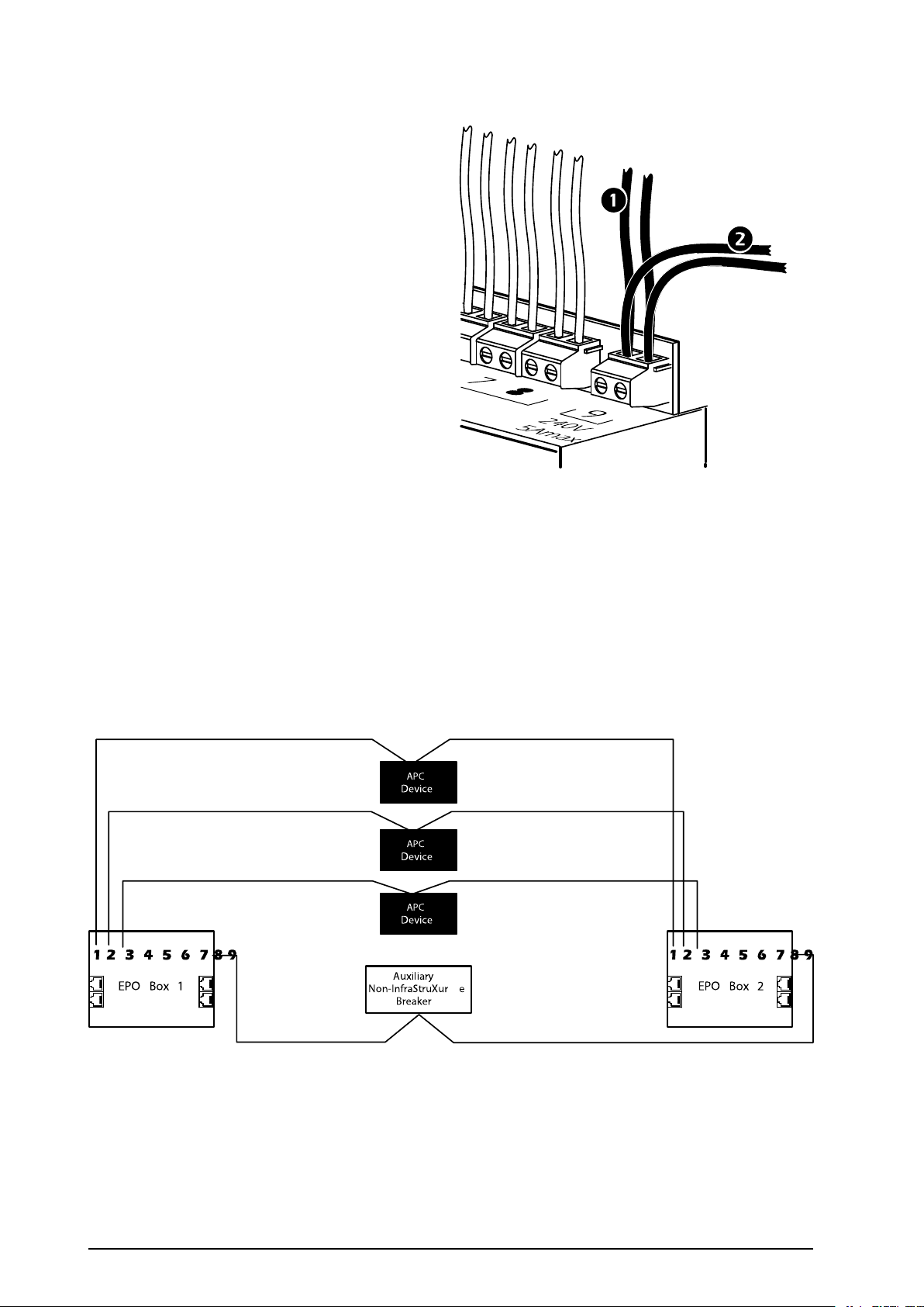
CascadetheAuxiliaryDevicewithWirePairs
1
2
Auxiliary
Non-InfraSt ruXur e
Breaker
Device
Device
Device
EPO Box 1 EPO Box 2
APC
APC
APC
1.Afterwiresarerunfromauxiliarydevice(1)
toterminalblockposition9,runasecondset
ofwires(2)fromterminalblockposition9on
therstEPOboxtoterminalblockposition9
onthesecondEPObox.
2.Continueuntilallboxesareconnected.(See
thediagramin“CascadeMultipleEPO
Boxes“forreference.)
DirectWiringAlternative
IftheAPCdevicesarecentrallylocatedbetweenexitdoors,itmaybemorepracticaltorunseparatewire
pairsfromthedevicestoeachEPObox.Thiswiringmethodrequiresterminalblockconnectionsinevery
EPObox,ratherthancascadingcablesbetweenboxes.ConnectwirepairsfromtheNormallyOpen(NO)
contactsonthedevicestoeachEPObox.Becausethisalternativeresultsinmultiplewirepairsatthe
terminalsofthedevices,APCdoesnotrecommendusingitwithmorethanthreeEPOboxes.
VerifyConnectionsateachEPOBox
1.Verifythatthewiringiscorrectbeforeattachingcriticalloaddevicestoyourdevices:
A.WiththedevicespoweredON,useasmalltooltopresseachcheckpoint,oneatatime.
12
EmergencyPowerOffSystemInstallationandOperation
990–1611C-001
Page 17
Note:IfanAPCFMSeriesPrecisionAirConditioningSystemconnectedtotheEPObox,
pressingthecheckpointwillshutofffunctionalitytotheunit,buttheunitwillstillbe
powered.
B.Afterverifyingthewiring,closethesystembox,makingsurenottopinwiresordisturb
connections,andsecurewiththescrews,previouslyremovedwhenopeningthebox.
C.Asanaltest,applypowertoallAPCdevicesandauxiliarydevices,andpresstheEPO
button.AllconnecteddevicesshouldpowerOFFimmediately.Repeatthisnaltestatevery
EPOboxinthesystem.
WARNING:Pressingthecheckpointwillshutdowntheconnecteddeviceandany
loaditissupporting.
990–1611C-001
EmergencyPowerOffSystemInstallationandOperation
13
Page 18

Operation
1
2
EngagetheSystem
1.LifttheshieldonanyoftheinstalledEPO
boxesandpressthebutton.Aredagwill
dropdownfromthebox,providinganeasy
visualmarkastowhichEPOboxinyourroom
hasbeenactivated.
ResettheEPOSystem
1.Pullthebuttontowardsyou(1)andpushthe
agupuntilitcatches(2).Pullingthebutton
doesnotbringpowerbacktotheconnected
equipment;itonlyresetstheEPOsystem.
Closetheshieldafterresettingthesystem.
14
EmergencyPowerOffSystemInstallationandOperation
990–1611C-001
Page 19

ResettheEquipment
Applypowertothedevicesaccordingtotheproceduresforeachdevice.
Note:Refertotheoperationmanualincludedwitheachdeviceforspecicinstructionson
howtoapplypowertothedevice.
990–1611C-001
EmergencyPowerOffSystemInstallationandOperation
15
Page 20
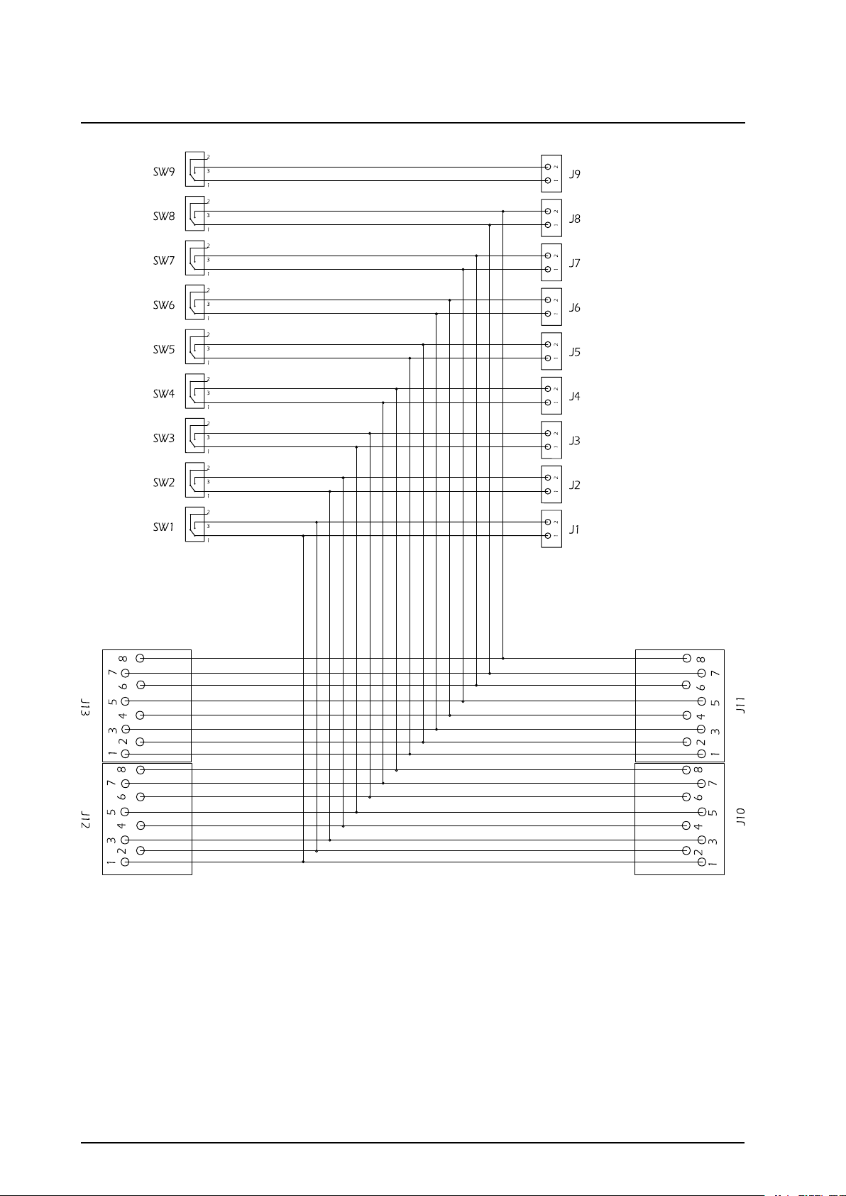
WiringDiagram
16
EmergencyPowerOffSystemInstallationandOperation
990–1611C-001
Page 21

990–1611C-001
EmergencyPowerOffSystemInstallationandOperation
17
Page 22

Page 23

Page 24

WorldwideCustomerSupport
Customersupportisavailableatnochargeviae-mailortelephone.Contactinformationisavailableat
www.apc.com/support/contact
©SchneiderElectric.APCandtheAPClogoareownedbySchneiderElectricIndustriesS.A.S.or
theirafliatedcompanies.Allothertrademarksarepropertyoftheirrespectiveowners.
990–1611C-00112/2012
 Loading...