

Page 1

Contents
Features of the System--1
Introduction . . . . . . . . . . . . . . . . . . . . . . . . . . . . . . . . . . . . . . . 1
Battery Management Capabilities . . . . . . . . . . . . . . . . . . . . . . . . . 2
System capacity 2
Battery management features 3
Network Management Features
Supported network management applications 4
Supported Web browsers 5
Getting Started--6
Initial Setup. . . . . . . . . . . . . . . . . . . . . . . . . . . . . . . . . . . . . . . . 6
Configuring TCP/IP settings 6
Useful terms 7
Accessing the User Interfaces--8
Access Procedures . . . . . . . . . . . . . . . . . . . . . . . . . . . . . . . . . . . 8
Access priorities among the interfaces 8
Access priority for logging on 8
Web interface 9
Control console interface 10
SNMP interface 12
Password-protected Accounts
Account types and access 13
How to recover from a lost password 14
Watchdog Features
Network interface watchdog mechanism 16
Resetting the network timer 16
. . . . . . . . . . . . . . . . . . . . . . . . . . . . . . . . . 16
. . . . . . . . . . . . . . . . . . . . . . . . . . 4
. . . . . . . . . . . . . . . . . . . . . . . . . . 13
USER’S GUIDE
Battery Management System
®
I
Page 2

Battery Management--17
Main Screen . . . . . . . . . . . . . . . . . . . . . . . . . . . . . . . . . . . . . . 17
General system information 17
Battery System and Device Manager Menus
Displaying data and alarms 19
Viewing details on alarms 22
Interpreting alarm details 23
Configuration menu 27
Calibration menu 29
Modbus 30
Reset Discharge Voltages 31
Reset Charge Current Deviation Benchmark 31
Network Menu--32
Access Restrictions and Menu Options . . . . . . . . . . . . . . . . . . . . 32
Access 32
Menu options 32
Option Settings
TCP/IP 33
DNS 37
Ping utility (control console) 38
FTP Server 39
Telnet/SSH 40
SNMP 47
Email 48
Syslog 49
Web/SSL 52
. . . . . . . . . . . . . . . . . . . . . . . . . . . . . . . . . . . . 33
. . . . . . . . . . . . . . . . . 19
USER’S GUIDE
Battery Management System
®
II
Page 3

System Menu--61
Access Restrictions and Menu Options . . . . . . . . . . . . . . . . . . . . 61
Purpose and access 61
Menu options 62
Option Settings
User Manager 63
RADIUS 64
Identification 67
Date & Time 67
Tools 69
Preferences (Web interface) 71
Links (Web interface) 72
About System (control console) 73
. . . . . . . . . . . . . . . . . . . . . . . . . . . . . . . . . . . . 63
Event-related Menus--74
Introduction . . . . . . . . . . . . . . . . . . . . . . . . . . . . . . . . . . . . . . 74
Overview 74
Menu options 75
Event Log
Actions Option (Web interface only)
Recipients Option
USER’S GUIDE
Battery Management System
. . . . . . . . . . . . . . . . . . . . . . . . . . . . . . . . . . . . . . . . 76
Overview 76
Logged events 76
Accessing the log 77
How to use FTP or SCP to retrieve log files 78
Enabling and disabling event actions 81
Severity levels of events 81
Event Log action 81
SNMP Traps action 81
Email action 82
Related topics 82
. . . . . . . . . . . . . . . . . . . . . . . . . . . . . . . . . . 83
Trap Receivers 83
Email Recipients 84
Email Test 85
. . . . . . . . . . . . . . . . . . . . . 81
®
III
Page 4

Email Option . . . . . . . . . . . . . . . . . . . . . . . . . . . . . . . . . . . . . . 86
Requirements for using SMTP 86
DNS servers 87
SMTP settings 87
How to Configure Individual Events
Options to configure individual events 88
Event list access 88
Event list format 89
Event mask settings 89
Event mask example 91
Management Card and Battery Manager Events
Event generation 92
Discharge cycle counter 92
Severity levels defined 93
Management Card events 94
Battery Management System events 97
Data Logging (Web interface)--99
Description . . . . . . . . . . . . . . . . . . . . . . . . . . . . . . . . . . . . . . . 99
Configuration . . . . . . . . . . . . . . . . . . . . . . . . . . . . . . . . . . . . 100
. . . . . . . . . . . . . . . . . . . . . . 88
. . . . . . . . . . . . . . 92
Boot Mode--101
Introduction . . . . . . . . . . . . . . . . . . . . . . . . . . . . . . . . . . . . . 101
Overview 101
DHCP & BOOTP boot process 102
DHCP Configuration Settings
Management Card settings 104
DHCP response options 106
. . . . . . . . . . . . . . . . . . . . . . . . . . 104
Security--110
Security Features . . . . . . . . . . . . . . . . . . . . . . . . . . . . . . . . . . 110
Planning and implementing security features 110
Summary of access methods 110
Changing default user names and passwords
USER’S GUIDE
Battery Management System
®
immediately 112
Port assignments 112
User names, passwords, community names (SNMP) 113
IV
Page 5

Authentication. . . . . . . . . . . . . . . . . . . . . . . . . . . . . . . . . . . . 114
Authentication versus encryption 114
Encryption
Creating and Installing Digital Certificates
Firewalls
. . . . . . . . . . . . . . . . . . . . . . . . . . . . . . . . . . . . . . 115
Secure SHell (SSH) and Secure CoPy (SCP) 115
Secure Sockets Layer (SSL) 117
Purpose 119
Choosing a method for your system 120
. . . . . . . . . . . . . . . . . . . . . . . . . . . . . . . . . . . . . . . . 126
Using the APC Security Wizard--127
Overview . . . . . . . . . . . . . . . . . . . . . . . . . . . . . . . . . . . . . . . 127
Authentication 127
Files you create for SSL and SSH security 129
Create a Root Certificate & Server Certificates
Summary 131
The procedure 132
Create a Server Certificate and Signing Request
Summary 137
The procedure 138
Create an SSH Host Key
Summary 142
The procedure 142
. . . . . . . . . . . . . . . . . . . . . . . . . . . . . 142
. . . . . . . . . . . . . . . . . 119
. . . . . . . . . . . . . . 131
. . . . . . . . . . . . . 137
How to Export Configuration Settings--145
Retrieving and Exporting the .ini file . . . . . . . . . . . . . . . . . . . . 145
Summary of the procedure 145
Contents of the .ini file 146
Detailed procedures 147
The event and its error messages 150
Messages in config.ini 151
Errors generated by overridden values 151
Using the Device IP Configuration Wizard
USER’S GUIDE
Battery Management System
®
V
. . . . . . . . . . . . . . . . . 152
Page 6

APC Device IP Configuration Wizard--153
Purpose and Requirements . . . . . . . . . . . . . . . . . . . . . . . . . . . 153
Purpose: configure basic TCP/IP settings 153
System requirements 153
Install the Wizard
Download the wizard 154
Use the Wizard
Launch the Wizard 155
Configure the basic TCP/IP settings remotely 155
Configure or reconfigure the TCP/IP settings locally 157
. . . . . . . . . . . . . . . . . . . . . . . . . . . . . . . . . . 154
. . . . . . . . . . . . . . . . . . . . . . . . . . . . . . . . . . . 155
File Transfers--158
Introduction . . . . . . . . . . . . . . . . . . . . . . . . . . . . . . . . . . . . . 158
Overview 158
Upgrading Firmware
Firmware defined 159
Benefits of upgrading firmware 159
Obtain the latest firmware version 160
Firmware files (Battery Management System) 161
Firmware file transfer methods 162
Use FTP or SCP to upgrade one Battery Management
System Management Card 163
Use FTP or SCP to upgrade multiple Battery Management
System Management Cards 166
Use XMODEM to upgrade one Battery Management
System Management Card 166
Verifying Upgrades and Updates
Overview 168
Last Transfer Result codes 168
. . . . . . . . . . . . . . . . . . . . . . . . . . . . . . . 159
. . . . . . . . . . . . . . . . . . . . . . . 168
Alarms--169
Fault Alarm Criteria . . . . . . . . . . . . . . . . . . . . . . . . . . . . . . . . 169
Alarm Relay and LED Operation . . . . . . . . . . . . . . . . . . . . . . . . 170
USER’S GUIDE
Battery Management System
®
VI
Page 7

Troubleshooting--171
Management Card . . . . . . . . . . . . . . . . . . . . . . . . . . . . . . . . . 171
Access problems (Battery Management System
Management Card) 171
SNMP issues (Battery Management System Management
Card) 173
Product Information--174
Limited warranty 174
Warranty limitations 174
Obtaining service (service contracts)
Life-Support Policy . . . . . . . . . . . . . . . . . . . . . . . . . . . . . . . . . 176
General policy 176
Examples of life-support devices 176
Index--177
APC Worldwide Customer Support . . . . . . . . . . . . . . . . . . . . . . 186
. . . . . . . . . . . . . . . . . . . . . 175
USER’S GUIDE
Battery Management System
®
VII
Page 8
Features of the System
Introduction
The APC Battery Management System provides automated monitoring of
large battery systems that supply backup for 120-, 240-, and 480-volt power
systems. The Battery Management System provides battery management
for nominal 2 V, 4 V, 8 V, or 12 V lead-acid batteries; or 1.2 V or 2.4 V nickelcadmium batteries.
The Battery Management System is controlled through a network interface
provided by a Network Management Card built into the master controller
(the first unit in a group of up to 6 total units). This card uses the open
standards Telnet, SSH, HTTP, SSL, RS-485 Modbus, RS-232 serial
connection, e-mail, and SNMP to manage the Battery Management
System.
For more information see Network Management Features
and Network Menu.
USER’S GUIDE
Battery Management System
®
1
Page 9

Battery Management Capabilities
System capacity
Using the APC Battery Management System, you can monitor and maintain
the batteries of one master unit and up to five expansion units, each unit
handling up to 64 individual batteries.
Five battery management expansion units can be connected in a group to
one master unit. The master unit provides the network connection through
its built-in management card so that the entire group can be managed
remotely through either one IP address or a serial connection.
The Battery Management System will support up to 244 lead-acid batteries
or up to 375 nickel-cadmium batteries.
To install and connect the system, see the Installation and
Quick Start manual
(.\doc\en\insguide.pdf), provided in
See also
USER’S GUIDE
Battery Management System
®
Portable Document Format (PDF) on the APC Battery
Management System Utility CD and in printed form.
2
Page 10

Battery management features
The system enables you to do the following:
• Identify weak or defective batteries that need replacement.
• Optimize the charge state of batteries within a string by automated
charging of individual batteries with a lower voltage. Charging these
batteries causes the batteries with high voltage to normalize. All the
batteries in the string become properly charged. This extends the
useful life of overcharged batteries and achieves full capacity of
undercharged batteries.
• Be alerted to alarm conditions that are displayed and logged to warn of
battery system or Battery Management System conditions.
USER’S GUIDE
Battery Management System
®
3
Page 11

Network Management Features
Supported network management applications
An APC Network Management Card (AP9517SQD) is built into the master
controller (AP9921X) that provides the network connection. It is the first
battery management unit in a group of one master unit and up to 5
expansion units (AP9921XS).
The Battery Management System supports the following access methods:
Network Connection Access Description
Telnet & SSH APC control
console
interface
HTTP & SSL Web browser A graphical user interface to the Battery
SNMP MIB browser Uses MIB II OIDs to configure the built-in
FTP Device IP
Configuration
Wizard
Display interface
(optional)
USER’S GUIDE
Battery Management System
LCD display Remote LCD interface through which you
A non-graphical interface through which
you can configure network, system, and
battery management parameters, and
display and monitor battery management
data.
Management System through a standard
Web browser. With this Web interface, you
can configure network, system, and battery
management parameters, and display and
monitor battery management data.
management card, and use SNMP traps to
report Battery Management System events.
Consecutively discovers each unconfigured
controller on the same network segment
and enables you to configure its basic
TCP/IP settings remotely.
can configure network, system, and battery
management data.
®
4
Page 12

Supported Web browsers
As your browser, you can use Microsoft® Internet Explorer (IE) 5.x or
Netscape
interface. Other commonly available browsers also may work but have not
been fully tested by APC.
Data verification, the event log, and the data log authentication require that
you enable the following for your Web browser:
• JavaScript
•Java
• Cookies
In addition, the Battery Management System cannot work with a proxy
server. Therefore, before you can use a Web browser to access its Web
interface, you must do one of the following:
• Configure the Web browser to disable the use of a proxy server for the
®
7.x to access the Battery Management System through its Web
Battery Management System.
• Configure the proxy server so that it does not proxy the specific IP
address of the Battery Management System.
USER’S GUIDE
Battery Management System
®
5
Page 13

Getting Started
Initial Setup
Configuring TCP/IP settings
You must define three TCP/IP settings for the Battery Management
System’s built-in Management Card before the Battery Management
System can be managed over the network:
• IP address of the Battery Management System
• Subnet mask
• IP address of the default gateway
Choose one of the following methods to configure the TCP/IP settings:
• With the Device IP Configuration Wizard, which you install from the
CD. This method is available only for Windows
Windows 2003, and Windows XP.
®
NT, Windows 2000,
• By a direct serial connection from the Network Configuration port on
the controller to a serial port on your computer.
• Using ARP and Telnet, if your computer is on the same subnet as the
Battery Management System.
• Through a BOOTP or DHCP server.
For detailed instructions on these methods of configuring the
TCP/IP settings, see “Quick Configuration” in the Installation and
See also
USER’S GUIDE
Battery Management System
®
Quick Start manual (.\doc\en\insguide.pdf), provided in Portable
Document Format (PDF) on the APC Battery Management
System for High Voltage Applications Utility CD and in printed
form.
6
Page 14

‘
To configure multiple Battery Management Systems, see
How to Export Configuration Settings.
Useful terms
Batteries: Single or multi-cell lead-acid or nickel-cadmium blocks that are
connected together in series to create a string.
Battery Management System: One complete Battery Management
System that is composed of one master unit and up to five expansion units.
Battery Management Unit: A single enclosure within a group of enclosures
that operate together as a system.
Current acceptance: The amount of current that flows into an individual
battery from the Battery Management System’s electrically isolated DC
boost supply.
Float charge: The power provided to a battery by the battery charger to
sustain the charge.
Jar: An individual battery.
Management Controller: The Battery Management System and
associated sensors, wiring, fuses, and cables.
Pilot battery: A single battery that is monitored as a representation of the
entire string of batteries.
String current: The common current flowing through the string of batteries.
The current polarity can be positive when flowing into the string, as during a
charge, or negative when flowing from the string, as during a discharge.
USER’S GUIDE
Battery Management System
®
This current has the same value throughout the string.
7
Page 15
Accessing the User Interfaces
Access Procedures
Access priorities among the interfaces
After the Battery Management System network settings are configured (as
described in the Installation and Quick Start Manual), you can use the
Battery Management System remotely through its Web, control console
(Telnet or SSH), and SNMP interfaces.
Access priority for logging on
Only one user at a time can log on to the Battery Management System to
use its internal user interface features. The priority for access is as follows:
• Local access to the control console from a computer with a direct serial
connection to the Battery Management System always has the highest
priority.
• Telnet or Secure SHell (SSH) access to the control console from a
remote computer has priority over Web access.
• Web access, either directly or through the InfraStruXure Manager, has
the lowest priority.
For information about how SNMP access to the Battery
Management System is controlled, see SNMP.
USER’S GUIDE
Battery Management System
®
8
Page 16

Web interface
To access and log on to the Battery Management System’s Web interface:
1. In the URL Location field, do one of the following.
– If the Battery Management System port is set to the default value of
80, type http:// followed by the Battery Management System IP
address. The following example shows a typical IP address:
http://170.241.17.51 if HTTP is your access mode
https://170.241.17.51 if HTTPS (SSL/TLS) is your access
mode
– If the Battery Management System Web port is set to a value other
than the default of 80, enter the System IP address (the IP address
of the Battery Management System) followed by a colon and the
configured Web Port value (8000 in the following example):
http://170.241.17.51:8000 if HTTP is your access mode
https://170.241.17.51:8000 if HTTPS (SSL/TLS) is your
access mode
– If there is a DNS server entry for the Battery Management System,
you can enter the DNS name. For example:
http://DeviceNumber25 if HTTP is your access mode
https://DeviceNumber25 if HTTPS (SSL/TLS) is your access
mode
2. Respond to the User Name and Password prompts. The default
Administrator user name and password are both apc, all lowercase.
In the Web interface, data verification requires that you
enable JavaScript or Java.
USER’S GUIDE
Battery Management System
®
9
Page 17

Control console interface
You can manage the Battery Management System through the control
console, using either Telnet or the RS-232/485 port.
Structure. The control console provides menu options to manage the
Battery Management System over the network.
To use an option, type its number and press
On menus that allow you to change a setting, you must use the Accept
Changes option to save changes.
While using a menu, you can also use the following keystrokes:
Keystrokes Actions
Press ? and then
Press
Press
Press
Press
ENTER Refreshes the menu.
ESC Returns to the previous menu.
CTRL+C Returns to the first menu.
CTRL+L Accesses the Battery Management System event log.
ENTER Provides brief menu option descriptions (if the menu has
help available).
ENTER.
USER’S GUIDE
Battery Management System
®
10
Page 18

Local access to the control console. You can use a local computer, a
computer that connects to the Battery Management System through the
serial port, to access the control console.
1. Select a serial port at the local computer and disable any service which
uses that port.
2. Connect the serial cable (940-0103) that came with the Battery
Management System to the RS-232/485 port on the Battery
Management Unit and a serial port on your local computer.
Modbus and the control console share a common serial port.
You can use either one or the other to access the Battery
Management System. If you reconfigure the DIP switches to
switch from Modbus to the control console, you must restart
the computer for the changed to take effect.
If you are using Modbus to access the Battery Management
System, you must configure the DIP switches. For DIP switch
configuration, see “Configure the DIP Switches” in the Installation
See also
3. Run a terminal program (such as HyperTerminal) and configure the
selected port for 9600 bps or 19200 (depending on the speed
configured for Modbus), 8 data bits, no parity, 1 stop bit, and no flow
control. Save the changes.
4. Press
5. Enter your user name and password (apc by default).
USER’S GUIDE
Battery Management System
®
and Quick Start Manual (.\doc\en\insguide.pdf), provided in
Portable Document Format (PDF) on the APC Battery
Management System Utility CD and in printed form.
ENTER twice to display the User Name prompt.
11
Page 19

Tel ne t. To access the Battery Management System’s control console using
Telnet:
1. Use the command telnet and the IP address of the Battery
Management System. For example:
telnet 170.215.6.49
2. Press the ENTER key to open the Telnet session and display the User
Name prompt.
Logging on. To log on to the control console, respond to the User Name
and Password prompts. The default user name and password for the
Administrator account are both apc, all lowercase. You can change the user
name, password, and time-out values through the System menu.
See User Manager.
SNMP interface
To use SNMP to configure the Management Card or to use the Battery
Management System traps for event notification, you must use version
3.6.9 (or later) of the APC PowerNet MIB.
See the APC MIB Reference Guide (.\doc\en\mibguide.pdf)
provided on the APC Battery Management System Utility
See also
USER’S GUIDE
Battery Management System
®
CD.
12
Page 20

Password-protected Accounts
Account types and access
The Battery Management System has three types of accounts,
Administrator, Device Manager and Read-Only User.
• The Administrator account can use all the menus in the control console
and in the Web interface. The default password and user name are
both apc.
• The Device Manager account can use only the following menus:
– In the Web interface, the Battery System menu and read-only
access for the Log option of the Events menu.
– In the control console, the Device Manager menu.
The default user name is device, and the default password is apc.
• A Read-Only User has the following restricted access:
– Access through the Web interface only.
– Access to the same menus as a Device Manager, but without the
capability to change configurations, control devices, or delete data.
Links to configuration options may be visible but are disabled, and
the event and data logs display no Delete button.
The Read-Only User’s default user name is readonly, and the default
password is apc.
To set the user names and passwords for the three account
types, see User Manager.
You must use the Web interface to configure values for the
Read-Only User.
USER’S GUIDE
Battery Management System
®
13
Page 21

How to recover from a lost password
You can use a local computer that connects to the Battery Management
System through the serial port on the rear of the master unit.
1. Select a serial port at a local computer, and disable any service that
uses the port.
2. Reset the DIP switch #6 and #7 to the OFF postion.
3. Use the configuration cable (APC part number 940-0103) to connect
the selected port to the serial port on the rear panel of the master unit.
Modbus and the control console share a common serial port.
You can use either one or the other to access the Battery
Management System. If you reconfigure the DIP switches to
switch from Modbus to the control console, you must restart
the computer for the changed to take effect
If you are using Modbus to access the Battery Management
System, you must configure the DIP switches. For DIP switch
configuration, see “Configure the DIP Switches” in the
See also
4. Run a terminal program (such as HyperTerminal
and configure the selected port as follows:
– 9600 bps (or 19200 bps, if you are using Modbus configured at that
rate)
– 8 data bits
– no parity
– 1 stop bit
USER’S GUIDE
Battery Management System
®
– no flow control
Installation and Quick Start Manual (.\doc\en\insguide.pdf),
provided in Portable Document Format (PDF) on the APC
Battery Management System Utility CD and in printed form.
14
®
) on your computer
Page 22

Modbus runs at 9600 or 19200 bps. To use the control
console when Modbus is enabled, your computer’s serial
port must communicate at the same serial protocol rate as
Modbus.
5. Press ENTER, repeatedly if necessary, to display the User Name
prompt. If you are unable to display the User Name prompt, verify the
following:
– The serial port is not in use by another application.
– The terminal settings are correct as specified in step 4.
– The correct cable is being used as specified in step 3.
6. Press the
Battery Management System. The Status LED will flash alternately
orange and green. Press the
while the LED is flashing to reset the user name and password to their
defaults temporarily
7. Press ENTER as many times as necessary to redisplay the User Name
prompt, then use the default, apc, for the user name and password. (If
you take longer than 30 seconds to log on after the User Name prompt
is redisplayed, you must repeat step 6 and log on again.)
8. From the Control Console menu, select System, then User
Manager.
9. Select Administrator, and change the User Name and Password
settings, both of which are now defined as apc. Select Accept
Changes to save your settings.
10. Press
and restart any service you disabled.
11. Reset the DIP switches to the configuration you had prior to step 2.
USER’S GUIDE
Battery Management System
You must restart the Battery Management System if any changes are
RESET button on the rear panel of the master unit of the
RESET button a second time immediately
.
CTRL-C, log off, reconnect any serial cable you disconnected,
made to the DIP switches.
®
15
Page 23

Watchdog Features
Network interface watchdog mechanism
The master unit’s built-in Management Card implements internal watchdog
mechanisms to protect itself from becoming inaccessible over the network.
For example, if the management card does not receive any network traffic
for 9.5 minutes (either direct traffic, such as SNMP, or broadcast traffic,
such as an Address Resolution Protocol [ARP] request), it assumes that
there is a problem with its network interface and reboots itself.
Resetting the network timer
To ensure that the Management Card does not reboot if the network is quiet
for 9.5 minutes, the Management Card attempts to contact the default
gateway every 4.5 minutes. If the gateway is present, it responds to the
Management Card, and that response restarts the 9.5-minute timer.
If your application does not require or have a gateway, specify the IP
address of a computer that is running on the network most of the time and is
on the same subnet. The network traffic of that computer will restart the
seven-minute timer frequently enough to prevent the Management Card
from rebooting.
USER’S GUIDE
Battery Management System
®
16
Page 24

Battery Management
Main Screen
General system information
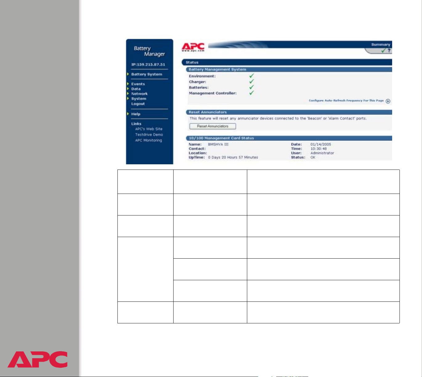
When you log on to the Web interface or control console, the main screen
provides basic information about the Battery Management System:
Information displayed in both interfaces. Both the Web and control
console interfaces display the following information:
• System Name, Contact, and Location for the Battery Management
System. To set these values, use the Identification option of the
System menu.
• Date and Time: The date and time at which you logged on. To change
the system date and time, use the System menu option, Date & Time.
• User: Whether you logged on as an Administrator, Device Manager, or
Read-Only User.
• Up Time: How long the Management Card has been running since it
was last turned on or reset.
• Status: The status of the master controller’s built-in Management
Card.
For information on the display interface, see “How to use the
display interface” in the Installation and Quick Start Manual
(.\doc\en\insguide.pdf), provided in Portable Document
See also
USER’S GUIDE
Battery Management System
®
Format (PDF) on the APC Battery Management System
Utility CD and in printed form.
17
Page 25
Information displayed in the control console only. The main screen of
the control console displays the following additional information.
• Version information: (In the Web interface, select About System
from the Help menu.)
– Battery Manager III APP: The version of the application (APP).
– Network Management Card AOS: The version of the APC
operating system (AOS) of the master unit’s built-in management
card.
• Status: The status of the master unit’s built-in Management Card.
The status codes are displayed in the control console only.
P+ The APC operating system (AOS) is functioning properly.
N+ The network is functioning properly.
A+ The application firmware is functioning properly.
A- The application firmware has a bad checksum.
A? The application firmware is initializing.
A! The application firmware is not compatible with the AOS.
If you can access the control console through Telnet, the
AOS reports P+, and the network reports N+.
USER’S GUIDE
Battery Management System
®
18
Page 26

Battery System and Device Manager Menus
Displaying data and alarms
You can display battery information and view alarms and their causes in the
Web interface, control console, or display interface.
To configure values related to the batteries, such as changing the threshold
values that define whether data are in-range (OK) or out-of-range (Alarm),
you can use either the Web interface or the control console.
See Configuration menu.
USER’S GUIDE
Battery Management System
®
19
Page 27
Web interface.
Alarm
category
Environment Ambient
Charger String Voltage The voltage (VDC) of an entire battery string,
Batteries Discharge Test The lowest voltage (VDC) of individual
Management
Controller
USER’S GUIDE
Battery Management System
®
Alarms reported Data causing the alarm
The air temperature in the battery environment
Temperature
discharge, and high pilot temperature.
batteries recorded during the last discharge
Charge Test The response of individual batteries to a boost
charge
Pilot Temperature The surface temperature of the battery to
which the pilot temperature sensor is attached
Blown Fuse/
Connections
No voltage is sensed from one or more
batteries.
20
Page 28

Control console.
You can use the control console to display battery information and alarms.
See Web interface.
To display battery data and active alarms:
1. On the main screen of the control console, identify the battery string
about which you want to display information. For each battery string a
hyphen (-) indicates no alarms, W indicates a warning condition, and S
indicates a severe condition.
2. Select Device Manager.
3. Select String Details.
4. Type the number for the data category.
USER’S GUIDE
Battery Management System
®
21
Page 29

Viewing details on alarms
You can display detailed information on active alarms for any battery string.
The alarm message text displayed for a category indicates which alarm
details to select.
Silcon battery systems have a maximum of two strings.
All other battery systems have only one string.
Web interface example.
1. On the main screen, the Charger column for a battery string displays a
red ALARM icon. Click on that icon or on the String Details option in
the Battery System menu to display the String Details screen.
2. For the battery string, the alarm message text is String voltage
is high. Under Individual Battery Details, click on Volta ge (the
reason for the alarm).
Control console example.
1. On the main screen, the Charger row in the column for the battery
string displays S, indicating an active severe alarm for the category.
2. From the control console main screen, type 1 to select the Device
Manager menu.
3. For the battery string, the alarm message text is String voltage
is high. Type 1, for Battery Voltage (the reason for the alarm).
USER’S GUIDE
Battery Management System
®
22
Page 30

Interpreting alarm details
For an alarm category:
• The Web interface displays detailed alarm data and any configured
threshold values on a single page. For the three types of battery
alarms, bar graphs are displayed. To view or change the threshold
values, you must use the Configuration menu option of the Battery
System menu in the Web interface.
• The control console displays detailed alarm data through numbered
menus.
– Values below the low threshold are indicated by the < character, and
values above the high threshold are indicated by the > character.
– To view or change the threshold values, select Device Manager and
then select String Details in the control console.
See Configuration menu to configure alarm details.
Environment alarms.
Category Details Diagnostics
Ambient
Temperature
USER’S GUIDE
Battery Management System
®
Input Contacts Activation of input
The air temperature in the
battery string environment
is above or below
configured thresholds.
Default:
50.0° F (10° C): low
threshold
95.0° F (35° C): high
threshold.
contacts triggers an
alarm.
23
Problem:
• Uncorrected high temperature can cause
• Uncorrected low temperature can cause a
Response: Check temperature control and
ventilation systems in the room, and check
for overheated batteries (usually caused by
overcharging).
Check the status of the external monitoring
device that sent the input signal.
permanent damage to the batteries.
reduction in battery runtime.
Page 31

Charger alarms.
Category Details Diagnostics
String Voltages The voltage of a battery
string is above or below
the threshold.
String Current The BMS has detected a
sufficient flow in the
discharge direction to
indicate a loss of the
charger value.
Ripple Current The detected ripple
current exceeds the alarm
threshold.
Problem: High or low string voltage
indicates that the string charger may
be defective or improperly adjusted. If
uncorrected, this condition can cause
permanent damage to the batteries.
Response: Adjust the DC string-
charging voltage to the proper setting.
Investigate the loss of power to the
charger and restore it as soon as
possible.
Investiage the source of high AC
current in the charger output.
Battery alarms.
Category Details Diagnostics
Discharge
Tes t
USER’S GUIDE
Battery Management System
®
The voltage of individual
batteries listed in the alarm
text dropped below the
configured minimum
threshold during the last
discharge.
24
Problem: Recorded voltage below the
minimum threshold indicates a battery
that will not perform adequately in
providing system backup in relation to
others in the same string.
Response: Replace failed batteries
immediately so that system backup time
is not reduced.
Page 32

Category Details Diagnostics
Charge Test When the Battery
Management System applied
a test current, the batteries
listed in the alarm message
showed a higher than
acceptable percentage
deviation from the previous
“benchmarked” values (which
are reset after any
discharge).
Pilot
Temperature
s
Sampling of the surface
temperature of one battery in
the string showed a
temperature above the
configured threshold.
Default:
95° F (35° C) (high
threshold).
Management Controller alarms.
Problem: A percentage deviation
outside the acceptable range indicates
unexplained changes that indicate the
need to verify possible problems with the
battery.
Response: Identify the listed batteries
immediately so that system backup time
is not reduced. Test and verify status of
the identified batteries immediately.
Problem: A high temperature alarm may
indicate an overheated (overcharged)
battery, usually caused by a faulty
charger.
Response: If uncorrected, this condition
can cause permanent damage to the
batteries. Replace failed batteries.
Category Details Diagnostics
Blown
Connection
Fuse
Missing or
Defective
Sensors
USER’S GUIDE
Battery Management System
®
The connections between the
Management Controller and
the batteries are open.
Not all sensors are present
and functional.
25
Problem: One or more fuses or wires
are open.
Response: Replace the fuse or wire
connection in the location indicated in
the event log.
Problem: The system operation is
not reliable without sensor
information.
Response: Connect or replace the
sensor indicated in the event log.
Page 33

Category Details Diagnostics
Monitor Relay
Stuck
Communication One or more units are not
A relay is stuck in the master
unit.
reporting to the master unit.
Reset the unit using the recessed
reset button on the back of the
master unit. If problem persists,
contact APC Customer Support at
the phone number located at the end
of this manual.
Problem: The system cannot
perform operations on all configured
batteries.
Response: Check that the cables on
the expansion ports are in place and
that the DIP switches are set
correctly.
USER’S GUIDE
Battery Management System
®
26
Page 34

Configuration menu
Battery Type Selection. Choose nickel-cadmium or lead-acid batteries.
Battery Configuration.
Charger Type (Silcon/
Other)
Number of Strings The number of strings in the system. Silcon may have two
Number of Batteries
per String
Number of Cells per
Battery
Monitor Wire Length Choose either >50 feet or <50 feet.
Cell Max Voltage
Limit
Cell Min Voltage Limit The minimum recommended voltage per individual battery
A Silcon unit can have two strings per battery management
master unit. Other requires a battery management master unit
for each new string.
battery strings, all other systems will have one.
The number of batteries in each string in the system. The
maximum number of batteries per string is 244 lead-acid
batteries or 375 nickel-cadmium batteries for a non-APC
Silcon UPS..
The number of cells per battery for nickel-cadmium batteries
is 1 or 2. The number of cells per battery for lead-acid
batteries is 1, 2, 4, or 6.
The maximum recommended voltage per individual battery
cell. This number multiplied by the total number cells in a
string equals the alarm value for the string. A charger alarm
occurs if the string voltage exceeds the alarm value.
cell. This number multiplied by the number of total cells in a
string equals the alarm value for the string. A charger alarm
occurs if the string voltage falls below the alarm value.
Battery Capacity Enter battery capacity in amp-hours for reference. The amp-
hour capacity of a battery should be clearly marked on the
actual battery.
USER’S GUIDE
Battery Management System
®
27
Page 35

Temperature Configuration.
Maximum Pilot
Temperature Limit
Maximum Ambient
Temperature Limit
Minimum Ambient
Temperature Limit
Alarm Configuration.
Ripple Current Limit
Charge Current Limit
The maximum surface temperature of the pilot battery in
the string (the battery to which the pilot temperature sensor
is attached). Because the Battery Management System
equalizes the charge for all batteries in the string, the
temperature of the pilot battery is likely to be typical of
other batteries in the string. For example, an overheated
pilot battery would probably indicate overcharging
throughout the string.
The maximum and minimum allowable temperature of the
air surrounding the batteries. See the specifications for
your batteries before changing this value.
Ripple current limit is the allowable AC
measurement in the battery string. The default
setting is 5 A for every 100 amp-hour of capacity.
Percentage of change in the response current
measurement that is allowed before an alarm is
indicated.
Discharge Voltage Limit
Automatic Annuciator Reset
USER’S GUIDE
Battery Management System
®
The percentage of the lowest individual battery
discharge voltage that is allowed relative to the
other batteries in the string.
When enabled, the external annunciator devices
will reset automatically when the condition of an
alarm clears. When disabled, the alarm must be
reset manually.
28
Page 36

Calibration menu
Select to calibrate either a String or a Unit.
String. Select the string you wish to calibrate.
String X
Ohmic Correction
Unit. Select the unit you wish to calibrate.
Unit X (Web interface)
DC Voltage Zero
DC Voltage Span
AC Ripple Zero
Ohmic Correction
Current Sensor Range
DC Current Sensor Zero
Each string will be listed. Select the
string you wish to configure
Set the overall Ohmic Correction
value.
Each unit will be listed.
Set to zero with no string current.
Set to 100, 200, 500, or 1000 A full
scale.
Set to zero with no string current.
Set to match calibrated instrument.
Set to 100, 200, 500, or 1000 A full
scale, based on current sensor
specifications.
Set to zero with no string current.
AC Current Sensor Zero
Tier Ohmic Value
USER’S GUIDE
Battery Management System
®
29
Set to zero with no string current.
Enter milliohms of cables and
connectors within the string to match
calibrated instrument.
Page 37

Modbus
Modbus lets you view the Battery Management System through your
building management services interface. It is read-only.
The Modbus interface supports 2-wire RS-485 with the following pin-out:
• Pin 2: TX/RX +
• Pin 3: TX/RX -
• Pin 5: GND
To configure Modbus using the Web interface, do the following:
• Select Modbus from the Battery System menu.
• Enter your settings.
To configure Modbus using the control console, do the following:
• Select Device Manager.
• Select Modbus.
• Enter your settings, including the baud rate at which your Modbus is
operating, either 9600 or 19200.
To use Modbus, do the following:
• Configure the DIP switches for Modbus operation.
To configure the DIP switches, see the Battery Management
System Installation and Quick Start Manual
See also
USER’S GUIDE
Battery Management System
®
See also
(.\doc\en\insguide.pdf), provided on the
Management System Utility CD.
The data that is available through the Modbus interface is defined
in a spreadsheet (.\doc\en\AP9920_MBRegMap_xx.xls)
provided on the APC Battery Management System Utility CD.
30
APC Battery
Page 38

Reset Discharge Voltages
Reset Lowest Discharge Voltages (control console). The lowest
discharge voltage is the lowest voltage measured for each battery in a
string during discharge. To clear the stored lowest discharge voltage:
1. Select Device Manager
2. Select Reset Discharge Voltages
3. Select Reset Lowest Discharge Voltages
Reset Lowest Discharge Voltages (Web interface). Select this option
from the Detailed Status menu of the Battery Management System
menu.
Reset Charge Current Deviation Benchmark
Reset Charge Current Deviation Benchmark (control console). The
response benchmark indicates the condition of the battery and the
connections to it. It is established when the system is commissioned, when
the batteries are replaced, or after a discharge.
1. The response benchmark is automatically cleared during a discharge.
To clear the stored response benchmark value and force it to be reset,
select Device Manager
2. Select Reset Response Benchmark
3. Select Reset Lowest Response Benchmark
Reset Charge Current Deviation Benchmark (Web interface). Select
this option from the Detailed Status menu of the Battery Management
System menu.
USER’S GUIDE
Battery Management System
®
31
Page 39

Network Menu
Access Restrictions and Menu Options
Access
Only an Administrator has access to the Network menu.
Menu options
To use the Network menu options to configure the network settings of the
Battery Management System, see the following descriptions:
• TCP/IP
• DNS
• Ping utility (control console)
• FTP Server
• Telnet/SSH
• SNMP
• Email
• Syslog
• Web/SSL
USER’S GUIDE
Battery Management System
®
32
Page 40

Option Settings
TCP/IP
This option accesses the following settings:
• Boot mode setting: Selects the method used to define the TCP/IP
values that a Battery Management System needs to operate on the
network:
– System IP: The IP address of the Battery Management System
– Subnet Mask: The subnet mask value
– Default Gateway: The IP address of the default gateway
For information about the watchdog role of the default
gateway, see
To configure the initial TCP/IP settings when you install the
Battery Management System, see the Battery
Management System Installation and Quick Start Manual
Resetting the network timer.
See also
• Advanced settings: Defines the Battery Management System’s host
and domain names, as well as Ethernet port speed, BOOTP, and
DHCP settings used by the Battery Management System.
Current TCP/IP settings fields. The current values for System IP,
Subnet Mask, and Default Gateway, and the Battery Management
System’s MAC Address, Host Name, Domain Name, and Ethernet Port
Speed values are displayed above the TCP/IP settings in the control
console and the Web interface.
USER’S GUIDE
Battery Management System
®
(.\doc\en\insguide.pdf), provided on the APC Battery
Management System Utility CD and in printed form.
33
Page 41

Boot mode setting. This setting selects which method will be used to
define the Battery Management System’s TCP/IP settings whenever the
Battery Management System turns on, resets, or restarts:
• Manual: Three settings (System IP, Subnet Mask, and Default
Gateway) which are available only when Manual is used to define the
needed TCP/IP settings.
• BOOTP only: A BOOTP server provides the TCP/IP settings.
• DHCP only: A DHCP server provides the TCP/IP settings.
• DHCP & BOOTP: The Battery Management System will attempt to get
its TCP/IP settings from a BOOTP server first, and then, if it cannot
discover a BOOTP server, from a DHCP server.
An After IP Assignment setting, by default, will switch Boot
mode from its default DHCP & BOOTP setting to BOOTP only or
DHCP only, depending on the type of server that supplied the
TCP/IP settings to the Battery Management System.
For information about the After IP Assignment setting and other
settings that affect how the Battery Management System uses
BOOTP and DHCP, see Advanced settings; for more information
on how to use DHCP, see Boot Mode.
USER’S GUIDE
Battery Management System
®
34
Page 42

Advanced settings. The Boot mode affects which settings are available:
• Two settings are available for all Boot mode selections to define the
Battery Management System’s Host Name and Domain Name
values.
– Host Name: When an Administrator configures a host name here
and a domain name in the Domain Name field, users can then enter
a host name in any field in the Battery Management System
interface (except e-mail addresses) that accepts a domain name as
input.
– Domain Name: An Administrator needs to configure the domain
name here only. In all other fields in the Battery Management
System interface (except e-mail addresses) that accept domain
names, the Battery Management System will add this domain name
when only a host name is entered.
To override the expansion of a specified host name by the
addition of the domain name, do one of the following:
• To override the behavior in all instances, set the
domain name field in Configure General Settings to
its default somedomain.com or to 0.0.0.0.
• To override the behavior for a particular host name
entry — for example when defining a trap receiver —
include a trailing period. The Battery Management
System recognizes a host name with a trailing period
(such as mySnmpServer.) as if it were a fully
qualified domain name and therefore does not append
the domain name.
•A Port Speed setting is available for all Boot mode selections to
USER’S GUIDE
Battery Management System
®
define the TCP/IP port’s communication speed (Auto-negotiate, by
default).
35
Page 43

• Three settings are available for all Boot mode selections, except
Manual, to identify the Management Card in BOOTP or DHCP
communication:
– Vendor Class: Uses APC, by default.
– Client ID: Uses the Battery Management System’s MAC address,
by default.
If the Client ID is changed from the Battery Management
System master unit’s MAC address, the new value must be
Caution
– User Class: Uses the Battery Management System’s application
firmware module type, by default. For example, a Battery
Management module sets the User Class to BMS-HVA.
• Two settings are available if BOOTP only is the Boot mode selection:
– Retry Then Fail: Defines how many times the Battery Management
System will attempt to discover a BOOTP server before it stops (4,
by default).
– On Retry Failure: Defines what TCP/IP settings will be used by the
Battery Management System when it fails to discover a BOOTP
server (Use Prior Settings, by default).
For information about the Advanced settings (DHCP Cookie Is
and Retry Then Stop) that directly affect how DHCP is used, see
Boot Mode.
unique on the LAN. Otherwise, the DHCP or BOOTP server
may act incorrectly.
USER’S GUIDE
Battery Management System
®
36
Page 44

DNS
Use this option to define the IP addresses of the primary and secondary
Domain Name System (DNS) servers used by the Battery Management
System’s e-mail feature. The primary DNS server will always be tried first.
See Email Recipients and DNS servers.
Send DNS Query (Web interface). Use this option, available only
through the DNS menu in the Web interface, to send a DNS query that tests
the setup of your DNS servers.
Use the following settings to define the parameters for the test DNS
request; you view the result of the test DNS request in the Last Query
Response field (which displays No last query or text describing the query
result of the last test).
• Use the Query Type setting to select the method to use for the DNS query:
– The URL name of the server (Host)
– The IP address of the server (IP)
– The fully qualified domain name (FQDN)
– The Mail Exchange used by the server (MX)
•Use the Query Question text field to identify the value to be used for the
selected Query Type:
–For Host, identify the URL.
–For IP, identify the IP address.
–For FQDN, identify the fully qualified domain name, formatted as
myserver.mydomain.com.
–For MX, identify the Mail Exchange address.
USER’S GUIDE
Battery Management System
®
37
Page 45

• Enable or disable Reverse DNS Lookup. This feature is disabled by
default. Enabling this feature is the recommended configuration, unless
you have no DNS server configured or have poor network performance
because of heavy network traffic. With Reverse DNS Lookup enabled,
when a network-related event occurs, reverse DNS lookup logs both
the IP address and the domain name for the networked device
associated with the event in the event log. If no domain name entry
exists for the device, only its IP address is logged with the event. Since
domain names generally change much less frequently than IP
addresses, enabling reverse DNS lookup can improve the ability to
identify addresses of networked devices that are causing events to
occur.
Ping utility (control console)
Select this option, available only in the control console, to check the Battery
Management System’s network connection by testing whether a defined IP
address or domain name responds to the Ping network utility. By default,
the default gateway IP address (see TCP/IP) is used. However, you can
use the IP address or domain name of any device known to be running on
the network.
USER’S GUIDE
Battery Management System
®
38
Page 46

FTP Server
Use the Access setting to enable or disable the FTP server. The server is
enabled by default.
FTP transfers files without using encryption. For higher security,
use Secure CoPy (SCP) for file transfers. When you select and
configure Secure SHell (SSH), SCP is enabled automatically. To
configure SSH, see Telnet/SSH. If you decide to use SCP for file
transfer, be sure to disable the FTP server.
To configure SSH, see Telnet/SSH. If you decide to use SCP
for file transfer, be sure to disable the FTP server.
Use the Port setting to identify the TCP/IP port that the FTP server uses for
communications with the Battery Management System. The default Port
setting is 21.
You can change the Port setting to any unused port from 5000 to 32768 to
enhance the protection provided by User Name and Password settings.
You must then use a colon (:) in the command line to specify the non-default
port. For example, for a port number of 5000 and a Battery Management
System IP address of 159.215.12.114, you would use this command:
ftp 159.215.12.114:5000
To access a text version of the Battery Management System’s
event or data log, see How to use FTP or SCP to retrieve log
files.
USER’S GUIDE
Battery Management System
®
39
Page 47

Telnet/SSH
Use the Telnet/SSH option to perform the following tasks:
• Enable or disable Telnet or the Secure SHell (SSH) protocol for remote
control console access.
– While SSH is enabled, you cannot use Telnet to access the control
console.
– Enabling SSH enables SCP automatically.
When SSH is enabled and its port and encryption ciphers
configured, no further configuration is required to use
SCP. (SCP uses the same configuration as SSH.)
– Do not enable both versions of SSH unless you require that both be
activated at the same time. (Security protocols use extensive
processing power.)
To use SSH, you must have an SSH client installed. Most
Linux and other UNIX
part of their installation, but Microsoft
systems do not. SSH clients are available from various
®
platforms include an SSH client as
Windows operating
vendors.
• Configure the port settings for Telnet and SSH.
• Select one or more data encryption algorithms for SSH, version 1, SSH
version 2, or both.
• In the Web interface, specify a host key file previously created with the
APC Security Wizard and load it to the Battery Management System.
USER’S GUIDE
Battery Management System
®
40
Page 48

From a command line interface, such as the command
prompt on Windows operating systems, you can use FTP or
Secure CoPy (SCP) to transfer the host key file. You must
transfer the file to location /sec on the Battery Management
System.
If you do not specify a host key file, the Battery Management
System generates an RSA host key of 768 bits, instead of the
1024-bit RSA host key that the Wizard creates. The Battery
Management System can take up to 5 minutes to create
this host key, and SSH is not accessible during that time.
• Display the fingerprint of the SSH host key for SSH versions 1 and 2.
Most SSH clients display the fingerprint at the start of a session.
Compare the fingerprint displayed by the client to the fingerprint that
you recorded from the Web interface or control console of the Battery
Management System.
If you are using SSH version 2, expect a noticeable delay
when logging on to the control console of the Battery
Management System. Although the delay is not long, it can
be mistaken for a problem because there is no explanatory
message.
USER’S GUIDE
Battery Management System
®
41
Page 49

Option Description
Telnet/SSH Network Configuration
Access Enables or disables the access method selected in Protocol Mode.
OTE: Enabling SSH automatically disables Telnet. To enable SSH,
N
change the setting and then click Next>> in the Web interface or choose
Accept Changes in the control console. You must then agree to the
license agreement that is displayed.
Protocol
Mode
Choose one of the following:
• Teln et:
encryption.
• Secure SHell (SSH), version 1: User names, passwords, and data are
transmitted in encrypted form. There is little or no delay when you are
logging on.
• Secure SHell (SSH), version 2: User names, passwords, and data are
transmitted in encrypted form, but with somewhat more protection than
version 1 from attempts to intercept, forge, or alter data during data
transmission. There is a noticeable delay when you are logging on to
the Battery Management System.
• Secure SHell (SSH), versions 1 and 2: Do not enable both versions of
SSH unless you require that both be activated at the same time.
(Security protocols use extensive processing power.)
User names, passwords, and data are transmitted without
USER’S GUIDE
Battery Management System
®
42
Page 50

Option Description
Telnet/SSH Port Configuration
Telnet Port Identifies the TCP/IP port used for communications by Telnet with the
Battery Management System. The default is 23.
You can change the Port setting to the number of any unused port
between 5000 and 32768 to enhance the protection provided by User
Name and Password settings. Then, according to the requirements of
your Telnet client program, you must use either a colon (:) or a space in
the command line to specify the non-default port number. For example,
for a port number of 5000 and a Battery Management System IP address
of 159.215.12.114, your Telnet client would require one or the other of the
following commands:
telnet 159.215.12.114:5000
telnet 159.215.12.114 5000
SSH Port Identifies the TCP/IP port used for communications by the Secure SHell
(SSH) protocol with the Battery Management System. The default is 22.
You can change the Port setting to the number of any unused port
between 5000 and 32768 to enhance the protection provided by User
Name and Password settings. See the documentation for your SSH
client for information on the command line format required to specify a
non-default port number when starting SSH.
USER’S GUIDE
Battery Management System
®
43
Page 51

Option Description
SSH Server Configuration
SSHv1
Encryption
Algorithms
SSHv2
Encryption
Algorithms
Enables or disables DES, and displays the status (always enabled) of
Blowfish, two encryption algorithms (block ciphers) compatible with
SSH, version 1, clients.
• DES: The key length is 56 bits.
• Blowfish: The key length is 128 bits. You cannot disable this algorithm.
NOTE: Not all SSH clients can use every algorithm. If your SSH client
cannot use Blowfish, you must also enable DES.
Enables or disables the following encryption algorithms (Block Ciphers)
that are compatible with SSH version 2 clients.
• 3DES (enabled by default): The key length is 168 bits.
• Blowfish (enabled by default): The key length is 128 bits.
• AES 128: The key length is 128 bits.
• AES 256: The key length is 256 bits.
OTE: Not all SSH clients can use every algorithm. Your SSH client
N
selects the algorithm that provides the highest security from among the
enabled algorithms that it is able to use. (If your SSH client cannot use
either of the default algorithms, you must enable an AES algorithm that it
can use.)
USER’S GUIDE
Battery Management System
®
44
Page 52

Option Description
SSH User Host Key File
Status The Status field indicates the status of the host key (private key). In the
control console, you display host key status by selecting Advanced SSH
Configuration.
• SSH Disabled: No host key in use: No host key has been transferred
to the Battery Management System, or a host key has been transferred
improperly.
OTE: A host key must be installed to the /sec directory of the Battery
N
Management System
• Generating: The Battery Management System is generating a host key
because no valid host key was installed in its /sec directory.
• Loading: A host key is being loaded (i.e., being activated on the Battery
Management System).
• Valid: The host key is valid. (If you install an invalid host key, the
Battery Management System discards it and generates a valid one.
However, a host key that the Battery Management System generates is
only 768 bits in length. A valid host key created by the APC Security
Wizard is 1024 bits.)
Filename You can create a host key file with the APC Security Wizard and then
upload it to the Battery Management System by using the Web interface.
Use the Browse button for the Filename field to locate the file, then click
Apply.
Alternatively, you can use FTP or Secure CoPy (SCP) to transfer the host
key file to the Battery Management System.
OTE: Creating and uploading a host key in advance reduces the time
N
required to enable SSH. If no host key is loaded when you enable SSH,
the Battery Management System creates one when it reboots. The
Battery Management System takes up to 5 minutes to create this
key, and the SSH server is not accessible during that time.
USER’S GUIDE
Battery Management System
®
45
Page 53

Option Description
SSH Host Key Fingerprint
SSH v1 Displays the SSH version 1 fingerprint for the host key. The fingerprint is
a unique identifier to further authenticate the host key. In the control
console, choose Advanced SSH Configuration and then Host Key
Information to display the fingerprint.
SSH v2 Displays the SSH version 2 fingerprint for the host key. The fingerprint is
a unique identifier to further authenticate the host key. In the control
console, choose Advanced SSH Configuration and then Host Key
Information to display the fingerprint.
USER’S GUIDE
Battery Management System
®
46
Page 54

SNMP
An Access option (Settings in the control console) enables (by default) or
disables SNMP. When SNMP is enabled, the Access Control settings
allow you to control how each of the four available SNMP channels is used.
To define up to four NMSs as trap receivers, see Trap Receivers;
to use SNMP to manage a UPS or an environmental monitor, see
the PowerNet
Reference Guide (.\doc\en\mibguide.pdf) on the APC Battery
Management System Utility CD.
Setting Definition
®
SNMP Management Information Base (MIB)
Community
Name
NMS IP/
Domain
Name
USER’S GUIDE
Battery Management System
This setting defines the password (maximum of 15 characters) which an
NMS that is defined by the NMS IP setting uses to access the channel.
Limits access to the NMS specified by a domain name or to the NMSs
specified by the format used for the IP address:
• A domain name allows only the NMS at that location to have access.
• 159.215.12.1 allows only the NMS with that IP address to have access.
• 159.215.12.255 allows access for any NMS on the 159.215.12 segment.
• 159.215.255.255 allows access for any NMS on the 159.215 segment.
• 159.255.255.255 allows access for any NMS on the 159 segment.
• 0.0.0.0 or 255.255.255.255 allows access for any NMS.
®
47
Page 55

Setting Definition
Access
Type
Selects how the NMS defined by the NMS IP setting can use the channel,
when that NMS uses the correct Community Name.
Read The NMS can use GETs at any time, but it can never use SETs.
Write The NMS can use GETs at any time, and can use SETs when
no one is logged on to the control console or Web interface.
Disabled The NMS cannot use GETs or SETs.
Write+ The NMS can use GETs and SETs at any time, even when
someone is logged on to the control console or Web interface.
Use the Email option to do the following:
• Define the SMTP server.
See SMTP settings.
• Configure e-mail recipients.
See Email Recipients.
.
In the Web Interface, you can click the link Configure the
Email Recipients on the page displayed by the Email
option, or go directly to the Recipients option of the Events
menu.
USER’S GUIDE
Battery Management System
®
48
Page 56

Syslog
By default, the Battery Management System can send messages to up to
four Syslog servers whenever Battery Management System or the
embedded management card events occur. The Syslog servers, which
must be specifically identified by their IP addresses or domain names,
record the events in a log that provides a centralized record of events that
occur at network devices.
Syslog (and the event log) will also record discharge events including:
• Discharge time and date
• Discharge ambient and pilot battery temperature
• Discharge measured current
• Amp-hours removed from battery during discharge
This user’s guide does not describe Syslog or its
configuration values in detail. For more information about
Syslog, see RFC3164, at www.ietf.org/rfc/rfc3164.
Syslog settings. Leave the Syslog settings, except the Server IP settings,
set to their defaults unless otherwise specified by the Syslog network or
system administrator.
Setting Definition
General Settings
Syslog Enables (by default) or disables the Syslog feature.
Facility Selects the facility code assigned to the Battery Management System’s
Syslog messages (User, by default).
OTE: Although several daemon-specific and process-specific selections
N
USER’S GUIDE
Battery Management System
®
are available, along with eight generic selections, User is the selection that
best defines the Syslog messages sent by the Battery Management
System.
49
Page 57

Setting Definition
Syslog Server Settings
Server IP/
Domain
Name
Port Identifies the user datagram protocol (UDP) port that the Battery
Local Priority (Severity Mapping)
Map to
Syslog’s
Priorities
Uses specific IP addresses or domain names to identify which of up to four
servers will receive Syslog messages sent by the Battery Management
System.
N
OTE: To use the Syslog feature, Server IP/Domain Name must be
defined for at least one server.
Management System will use to send Syslog messages. The default is
514, the number of the UDP port assigned to Syslog.
Maps each of the severity levels (Local Priority settings) that can be
assigned to Battery Management System and embedded management
card events to the available Syslog priorities. The following definitions are
from RFC3164:
• Emergency: The system is unusable
• Alert: Action must be taken immediately
• Critical: Critical conditions
• Error: Error conditions
• Warning: Warning conditions
• Notice: Normal but significant conditions
• Informational: Informational messages
• Debug: Debug-level messages
Following are the default settings for the four Local Priority settings:
• Severe is mapped to Critical
• Warning is mapped to Warning
• Informational is mapped to Info
• None (for events that have no severity level assigned) is mapped to Info
OTE: To disable sending Syslog messages for Severe, Warning, or
N
USER’S GUIDE
Battery Management System
®
Informational events, see Actions Option (Web interface only).
50
Page 58

Syslog test (Web interface). This option allows you to send a test
message to the Syslog servers configured in the Syslog Server section.
1. Select the priority you want to assign to the test message.
2. Define the test message, using any text that is formatted as described
in Syslog message format below. For example, APC: Test message,
meets the required message format.
3. Click Apply to have the Battery Management System send a Syslog
message that uses the defined Priority and Test Message settings.
Syslog message format. A Syslog message has three parts:
• The priority (PRI) part identifies the Syslog priority assigned to the
message’s event and the facility code assigned to messages sent by
the Battery Management System.
• The Header includes a time stamp and the IP address of the Battery
Management System.
• The message (MSG) part has two fields:
– A TAG field, which is followed by a colon and a space, identifies the
event type (APC or System, for example).
– A CONTENT field provides the event text, followed by a space and
the event code.
USER’S GUIDE
Battery Management System
®
51
Page 59

Web/SSL
Use the Web/SSL menu to perform the following tasks.
• Enable or disable the two protocols that provide access to the Web
interface of the Battery Management System:
– Hypertext Transfer Protocol (HTTP) provides access by user name
and password, but does not encrypt user names, passwords, and
data during transmission.
– Hypertext Transfer Protocol over Secure Socket Layer (HTTPS).
Secure Sockets Layer (SSL) encrypts user names, passwords, and
data during transmission and provides authentication of the Battery
Management System by means of digital certificates.
See Creating and Installing Digital Certificates to choose
among the several methods for using digital certificates.
• Configure the ports that each of the two protocols will use.
• Select the encryption ciphers that SSL will use.
• Identify whether a server certificate is installed on the Battery
Management System. If a certificate has been created with the APC
Security Wizard but is not installed:
– In the Web interface, browse to the certificate file and upload it to the
Battery Management System.
– Alternatively, use the Secure CoPy (SCP) protocol or FTP to upload
it to the location \sec on the Battery Management System.
USER’S GUIDE
Battery Management System
®
52
Page 60

Creating and uploading a server certificate in advance
reduces the time required to enable HTTPS (SSL/TLS). If no
server certificate is loaded when you enable HTTPS (SSL/
TLS), the Battery Management System creates one when it
reboots. The Battery Management System can take up to
5 minutes to create this certificate, and the SSL/TLS
server is not available during that time.
• Display the configured parameters of a digital server certificate, if one
is installed.
USER’S GUIDE
Battery Management System
®
53
Page 61
Option Description
Web/SSL Network Configuration
Access Enables or disables the access method selected in Protocol Mode.
Protocol Mode Choose one of the following:
• HTTP: User names, passwords, and data are transmitted without
encryption.
• HTTPS (SSL): User names, passwords and data are transmitted in
encrypted form, and digital certificates are used for authentication.
N
OTE: To enable HTTPS (SSL), change the setting and then click
Next>> in the Web interface, or choose Accept Changes in the
control console. You must then agree to the license agreement that is
displayed. To activate the changes you must log off and log back on to
the interface. When SSL is activated, your browser displays a lock
icon, usually at the bottom of the screen.
USER’S GUIDE
Battery Management System
®
54
Page 62

Option Description
HTTP/HTTPS Port Configuration
HTTP Port Identifies the TCP/IP port used for communications by HTTP with the
Battery Management System. The default is 80.
You can change the Port setting to the number of any unused port
between 5000 and 32768 to enhance the protection provided by User
Name and Password settings.
You must then use a colon (:) in the command line to specify the nondefault port number. For example, for a port number of 5000 and a
Battery Management System IP address of 171.215.12.114, you would
use this command:
http://171.215.12.114:5000
HTTPS Port Identifies the TCP/IP port used for communications by HTTPS with the
Battery Management System. The default is 443.
You can change the Port setting to the number of any unused port
between 5000 and 32768 to enhance the protection provided by User
Name and Password settings.
You must then use a colon (:) in the command line to specify the nondefault port number. For example, for a port number of 6502 and a
Battery Management System IP address of 171.215.12.114, you would
use this command:
https://171.215.12.114:6502
USER’S GUIDE
Battery Management System
®
55
Page 63

Option Description
SSL Server Configuration
CipherSuite Enables or disables the following SSL encryption ciphers and hash
algorithms. (To access these options in the control console, choose
Web/SSL, then Advanced SSL Configuration.)
N
OTE: All of these encryption ciphers and hash algorithms use the
RSA public key algorithm.
• DES (SSL_RSA_WITH_DES_CBC_SHA): a block cipher with a key
length of 56 bits. The Secure Hash Algorithm (SHA) is used for
authentication.
• RC4 (SSL_RSA_WITH_RC4_128_MD5): a stream cipher with a key
length of 128 bits, with an RSA key exchange algorithm, and with a
Message Digest 5 (MD5) hash algorithm used for authentication. This
selection is enabled by default.
• 3DES (SSL_RSA_WITH_3DES_EDE_CBC_SHA): a block cipher
with a key length of 168 bits. A Secure Hash Algorithm (SHA) is used
for authentication.
• RC4 (SSL_RSA_WITH_RC4_128_SHA): a stream cipher with a key
length of 128 bits. A Secure Hash Algorithm (SHA) is used for
authentication. This selection is enabled by default.
USER’S GUIDE
Battery Management System
®
56
Page 64

Option Description
SSL Server Certificate
Status:
The Status field indicates whether a server certificate is installed. (To
display the status in the control console, choose Web/SSL, then
Advanced SSL Configuration.)
•
Not installed: No certificate is installed on the Battery Management
System.
OTE:If you install a certificate by using FTP or SCP, you must
N
specify the correct location (
System.
Generating: The Battery Management System is generating a
•
certificate because no valid certificate was installed.
•
Loading: A certificate is being loaded (activated on the Battery
Management System).
Valid: A valid certificate was installed to or generated by the Battery
•
Management System.
Management System discards it and generates a valid one. However,
a certificate that the Battery Management System generates has
some limitations. See Method 1: Use the Battery Management
System’s auto-generated default certificate.)
(If you install an invalid certificate, the Battery
/sec) on the Battery Management
USER’S GUIDE
Battery Management System
®
57
Page 65

Option Description
SSL Server Certificate
Filename: You can create a server certificate with the APC Security Wizard and
then upload it to the Battery Management System by using the Web
interface. Use the
file, then click Apply. By default, the certificate is installed to the
correct location.
Alternatively, you can use FTP or Secure CoPy (SCP) to transfer the
server certificate to the Battery Management System. However, you
must specify the correct location (
System.
N
OTE: Creating and uploading a server certificate in advance reduces
the time required to enable HTTPS (SSL). If no server certificate is
loaded when you enable HTTPS (SSL), the Battery Management
System creates one when it reboots.
System can take up to 5 minutes to create this certificate,
and the SSL server is not available during that time.
Browse button for the Filename field to locate the
/sec) on the Battery Management
The Battery Management
USER’S GUIDE
Battery Management System
®
58
Page 66

Parameter Description
Current Certificate Details
Issued To: Common Name (CN): The IP Address or DNS name of the Battery
Management System, except if the server certificate was generated by
default by the Battery Management System. For a default server
certificate, the Common Name (CN) field displays the Management
Card’s serial number.
OTE: If an IP address was specified as the Common Name when the
N
certificate was created, use an IP address to log on to the Web interface
of the Battery Management System; if the DNS name was specified as
the Common Name, use the DNS name to log on. When you log on, if
you do not use the IP address or DNS name that was specified for the
certificate, authentication fails, and you receive an error message asking
if you want to continue.
Organization (O), Organizational Unit (OU), and Locality, Country:
The name, organizational unit, and location of the organization that is
using the server certificate. If the server certificate was generated by
default by the Battery Management System, the Organizational Unit
(OU) field displays “Internally Generated Certificate.”
Serial Number: The serial number of the server certificate.
Issued By: Common Name (CN): The Common Name as specified in the CA root
certificate, except if the server certificate was generated by default by the
Battery Management System. For a default server certificate, the
Common Name (CN) field displays the Management Card’s serial
number.
Organization (O) and Organizational Unit (OU): The name and
organizational unit of the organization that issued the server certificate. If
the server certificate was generated by default by the Battery
Management System, the Organizational Unit (OU) field displays
“Internally Generated Certificate.”
Validity:
USER’S GUIDE
Battery Management System
®
Issued on: The date and time at which the certificate was issued.
Expires on: The date and time at which the certificate expires.
59
Page 67

Parameter Description
Fingerprint: Each fingerprint is a long string of alphanumeric characters punctuated
by colons. A fingerprint is a unique identifier that you can use to further
authenticate the server. Record the fingerprints to compare with the
fingerprints contained in the certificate, as displayed in the browser.
• SHA1 Fingerprint: This fingerprint is created by a Secure Hash
Algorithm (SHA).
• MD5 Fingerprint: This fingerprint is created by a Message Digest 5
(MD5) algorithm.
USER’S GUIDE
Battery Management System
®
60
Page 68

System Menu
Access Restrictions and Menu Options
Purpose and access
Use the System menu to do the following tasks:
• Configure system identification, date and time settings, and access
parameters for the Administrator, Device Manager, and Read-Only
User accounts.
• Synchronize the Battery Management System’s real-time clock with a
Network Time Protocol (NTP) server.
• Reset or restart the Battery Management System interface.
• Define the URL links available in the Web interface.
• Set the units (Fahrenheit or Celsius) used for temperature displays.
• Access hardware and firmware information about the Battery
Management System.
• Download firmware files (control console only).
• Upload user configuration files to the Battery Management System
(control console only).
Only an Administrator has access to the System menu.
USER’S GUIDE
Battery Management System
®
61
Page 69

Menu options
See the following descriptions of the settings available from the System
menu options:
• User Manager
• RADIUS
• Identification
• Date & Time
• Tools
• Preferences (Web interface)
• Links (Web interface)
• About System (control console)
USER’S GUIDE
Battery Management System
®
62
Page 70

Option Settings
User Manager
Use this option to define the access values shared by the control console
and Web interface.
Setting Definition
Auto Logout Defines (in minutes) how long you can be inactive while logged
on to the control console or Web interface before you are logged
off automatically (3 minutes by default).
N
OTE: You can bypass the auto-logout feature of the Battery
Management System by configuring the auto-refresh feature to
keep the screen active.
Separate values for Administrator, Device Manager, and Read-Only User
User Name The case-sensitive name (maximum of 10 characters) used by
Administrator and Device Manager users to log on at the control
console or Web interface and by the Read-Only User to log on at
the Web interface. Default values are apc for Administrator
users, device for Device Manager users, and readonly for the
Read-Only User.
Password The case-sensitive password (10 characters or less) always
used to log on to the control console. (apc is the default for the
Password settings for the three account types.)
N
OTE: A Read-Only User cannot log on through the control
console.
USER’S GUIDE
Battery Management System
®
63
Page 71

RADIUS
RADIUS (Remote Authentication Dial-In User Service) is an authentication,
authorization, and accounting service. Use this option to centrally
administer remote access for each Battery Management System.
When a user accesses the Battery Management System, an authentication
request is sent to the RADIUS server to determine the user’s permission
level.
RADIUS user names are limited to 32 characters.
For more information on user permission levels, see Account
types and access.
RADIUS servers use port 1812 by default to authenticate
users. To use a different port, add a colon followed by the
new port number to the end of the RADIUS server name or
IP address.
USER’S GUIDE
Battery Management System
®
64
Page 72

RADIUS Setting Definition
Access Local Only: RADIUS is disabled. Access to the Battery
Management System is controlled by the local user
manager only.
RADIUS then Local: RADIUS is enabled. Contact the
RADIUS server first. If the RADIUS server fails to
authenticate the user, the local user manager will be
used to authenticate access to the Battery Management
System.
RADIUS Only: RADIUS is enabled. Only the RADIUS
server will be contacted. If the RADIUS server fails to
authenticate the user, access will be denied.
OTE: If RADIUS only is selected, the only way to
N
recover if the RADIUS server is unavailable is through
the serial console.
Primary Server The server name or IP address of the main RADIUS
server.
Primary Server Secret
Secondary Server
Secondary Server Secret
Timeout
USER’S GUIDE
Battery Management System
®
The shared secret between the primary RADIUS server
and the Battery Management System.
The server name or IP address of the secondary
RADIUS server.
The shared secret between the secondary RADIUS
server and the Battery Management System.
The time in seconds that the Battery Management
System waits for a response from the RADIUS server.
65
Page 73

Configuring the RADIUS server. You must configure your RADIUS
server to work with the Battery Management System. The following
example is specific to APC’s RADIUS server.
1. Define an APC vendor in your RADIUS server; 318 is APC’s Private
Enterprise Number assigned by the Internet Assigned Numbers
Authority (IANA).
2. Define a RADIUS vendor-specific attribute called APC-Service-
Type. This is an integer with an attribute identifier of 1.
3. Configure RADIUS users. The APC-Service-Type attribute must be
configured for each RADIUS user accessing the card. This attribute is
set to one of the following values, which correspond to an access level
on the Battery Management System.
1 - Administrator
2 - Device Manager
3 - Read-Only User
USER’S GUIDE
Battery Management System
®
66
Page 74

Identification
Use this option to define the System Name, Location, and Contact values
used by the SNMP agent for the management card that is built into the
master controller of the Battery Management System. The values defined
here are used for the MIB-II sysName, sysContact, and sysLocation
Object Identifications (OIDs).
For more information about the MIB-II OIDs, see the
PowerNet
Reference Guide (.\doc\en\mibguide.pdf) provided on the
APC Battery Management System Utility CD.
®
SNMP Management Information Base (MIB)
Date & Time
Use this option to set the time and date used by the Battery Management
System. The option displays the current settings, and allows you to change
those settings manually, or through a Network Time Protocol (NTP) Server.
Set Manually. Use this option in the Web interface, or Manual in the
control console, to define the date and time for the Battery Management
System.
An Apply Local Computer Time to System option, which is
available in the Web interface only, sets these values to match
the date and time settings of the computer you are using to
access the Web interface.
Synchronize with Network Time Protocol (NTP) Server
or Network Time Protocol (NTP) in the control console, to have an NTP
Server update the date and time for the Battery Management System
automatically.
USER’S GUIDE
Battery Management System
®
67
. Use this option,
Page 75

In the control console, use the NTP Client option to enable or
disable (the default) the NTP Server updates. In the Web interface,
use the Set Manually option to disable the updates.
Setting Definition
Primary NTP Server Identifies the IP address or domain name of the primary NTP
server.
Secondary NTP
Server
GMT Offset (Time
Zone)
Update Interval Defines how often, in hours, the Battery Management System
Identifies the IP address or domain name of the secondary NTP
server, when a secondary server is available.
Defines the offset from Greenwich Mean Time (GMT) based on
the Battery Management System’s time zone.
accesses the NTP Server for an update. The minimum is 1 hour;
the maximum is 8760 hours (1 year). Use Update Using NTP
Now to initiate an immediate update as well.
USER’S GUIDE
Battery Management System
®
68
Page 76

Too ls
Initiating an action. Use this drop-down list in the Web interface or the
equivalent menu options in the control console to restart the interface of the
Battery Management System, to reset some or all of its configuration
settings to their default values, or to delete SSH Host Keys and SSL
Certificates.
Action Definition
Reboot Management
Interface
Reset to Defaults Resets all configuration settings.
Reset to Defaults Except
TCP/IP
Reset Only TCP/IP to
Defaults
Delete SSH Host Keys
and SSL Certificates
Restarts the interface of the Battery Management System.
OTE: For information about how this affects the Boot
N
mode setting, see this table’s description of Reset Only
TCP/IP to Defaults.
Resets all configuration settings except the TCP/IP
settings.
Resets the TCP/IP settings only.
OTE: WIth Boot mode set to DHCP & BOOTP, its default
N
setting, the Battery Management System’s TCP/IP settings
must be defined by a DHCP or BOOTP server.
See TCP/IP.
Removes any SSH host key and server certificate on the
Battery Management System so that you can reconfigure
these components of your security system.
USER’S GUIDE
Battery Management System
®
69
Page 77

Uploading an initialization file (Web interface only). To transfer
configuration settings from a configured Battery Management System master
controller to the current Battery Management System master controller, export
the .ini file from the configured Battery Management System, select the Too ls
menu on the current Battery Management System, browse to the file, and click
Upload. The current Battery Management System imports the file and uses it
to set its own configuration. The Status field reports the progress of the
upload.
See How to Export Configuration Settings for information on the
content of the .ini file, how to preserve comments you add to the
file, and how to export settings to multiple Battery Management
System master controllers.
USER’S GUIDE
Battery Management System
®
70
Page 78

File Transfer (control console only). The File Transfer option of the
Tools menu provides two methods for file transfer over the network and
one for file transfer through a serial connection to the Battery Management
System.
Option Description
XMODEM Allows you to transfer either an .ini file or a firmware upgrade file to a
Battery Management System master controller using a terminal-emulation
program only when you use a local connection to the control console. To
connect to the control console locally, see Local access to the control
console.
FTP
Client
TFTP
Client
Use one of these two options to transfer either an .ini file or a firmware
upgrade file from an FTP or TFTP server of your organization (company,
agency, or department) to the current Battery Management System. These
options assume that your organization has a centralized system for
configuring or upgrading APC Management Cards (such as the one
contained in the Battery Management System’s master unit).
For FTP Client, you are prompted for a user name and password. For
either option, you are then prompted for the server address and the file to
transfer. After you supply that required information, the Battery
Management System transfers the file.
See How to Export Configuration Settings for information on the
content of the .ini file, how to preserve comments you add to the
file, and how to export settings to multiple Battery Management
Systems.
Preferences (Web interface)
Use this option to select either Fahrenheit or Celsius for the Battery
Management System’s temperature display.
USER’S GUIDE
Battery Management System
®
71
Page 79

Links (Web interface)
Use this option to modify the links to APC Web pages.
Setting Definition
User Links
Name Defines the link names that appear in the Links menu (by default,
APC’s Web Site, Testdrive Demo, and APC Monitoring).
URL
Access Links
APC Home Page Defines the URL address used by the APC logo at the top of all Web
Defines the URL addresses used by the links. By default, the
following URL addresses are used:
• http://www.apc.com (APC’s Web Site)
• http://testdrive.apc.com (Testdrive Demo)
interface pages (by default, http://www.apc.com).
USER’S GUIDE
Battery Management System
®
72
Page 80

About System (control console)
This option identifies hardware information for the Management Card,
including Model Number, Serial Number, Manufacture Date, Hardware
Revision, MAC Address, and Flash Type. The hardware information will
never change.
The About System menu also includes fields for system Flash Type and
the Type, Sector, and CRC 16 for each module.
In the Web interface, except for Flash Type, this hardware
information is reported by the About System option in the
Help menu.
USER’S GUIDE
Battery Management System
®
73
Page 81

Event-related Menus
Introduction
Overview
Use the options of the Events menu to do the following tasks:
• Access the Event Log.
• Define the actions to be taken when an event occurs, based on the
severity level of that event. (You must use the Web interface to define
which events will use which actions.)
– Event logging
– Syslog messages
– SNMP trap notification
– E-mail notification
To define which events will use which actions, see Event Log
and Options to configure individual events.
• Define up to four SNMP trap receivers, by NMS-specific IP address or
domain name, for event notifications by SNMP traps.
• Define up to four recipients for event notifications by e-mail.
USER’S GUIDE
Battery Management System
®
74
Page 82

Menu options
To access the event-related options:
• In the Web interface, use the Events menu.
• In the control console:
– Use the Email option in the Network menu to define the SMTP
server and e-mail recipients.
– Use the SNMP option in the Network menu to define the SNMP trap
receivers.
– Use
CTRL-L to access the event log from any menu.
For information about event-related settings and about the email
feature, see the following descriptions:
• Event Log
• Actions Option (Web interface only)
• Email Recipients
• Email Option
• How to Configure Individual Events
USER’S GUIDE
Battery Management System
®
75
Page 83

Event Log
Overview
The Battery Management System supports event logging.
Use any of the following to view the Event Log:
• Web interface
• Control console
• FTP
•SCP
• Display interface
Logged events
The event log records normal and abnormal Management Card (system)
events and Battery Management events. Any conditions that cause an
SNMP trap, except for SNMP authentication failures, are logged as events.
The event log will also log information regarding discharge events by the
Battery Management System.
To disable the logging of events based on their assigned severity level, use
the Actions option in the Web interface’s Events menu.
For a list of all events, see Management Card events and
Battery Management System events.
USER’S GUIDE
Battery Management System
®
76
Page 84

Accessing the log
The Web interface and control console display events in the
event log in reverse chronological order.
To view or clear the Battery Management System’s event log, use the Web
interface, control console, or FTP.
Web interface. To display the events in reverse chronological order, use
the Log option in the Events menu.
To clear all events from the log, use the Delete Log button.
Control console. Use the control console over the network (using Telnet)
to do the following:
• To display the event log, in reverse chronological order, press C
• To scroll through the events, use the space bar.
• To clear all events from the log, type d and press
the log.
USER’S GUIDE
Battery Management System
®
77
TRL+L.
ENTER while viewing
Page 85

How to use FTP or SCP to retrieve log files
If you are an Administrator or Device Manager, you can use FTP or SCP to
retrieve a tab-delineated event log file (event.txt) or data log file (data.txt)
that you can import into a spreadsheet application.
• The file reports all of the events or data recorded since the log was last
deleted.
• The file includes information that the event log and data log does not
display.
– The version of the file format (first field)
– The date and time the file was retrieved
– The Name, Contact, and Location values and IP address of the
Battery Management System
– The unique Event Code for each recorded event (event.txt file only)
The Battery Management System uses a four-digit year for
log entries. You may need to select a four-digit date format in
your spreadsheet application to display all four digits of the
year.
If you are using the encryption-based security protocols for your system,
use Secure CoPy (SCP) to retrieve the log file. (You should have FTP
disabled.)
If you are using unencrypted authentication methods for the security of your
system, use FTP to retrieve the log file.
s
See Security for information on the available protocols and
methods for setting up the type of security appropriate for your
needs.
USER’S GUIDE
Battery Management System
®
78
Page 86

To use SCP to retrieve the file. To use SCP to retrieve the event.txt file,
use the following command:
scp username@hostname_or_ip_address:data txt./data.txt
To use FTP to retrieve the file. To use FTP to retrieve the event.txt file:
1. At a command prompt, type ftp and the Battery Management
System’s IP address, and press
If the Port setting for FTP Server in the Network menu has changed
from its default value (21), you must use the non-default value in the
FTP command. For Windows FTP clients, use the following command,
including spaces. (For some FTP clients, you must use a colon instead
of a space between the IP address and the port number.)
ftp>open ip_address port_number
To use non-default port values to enhance security, see Port
assignments.
2. Use the case-sensitive User Name and Password for either an
Administrator or a Device Manager user to log on.
ENTER.
– For Administrator, apc is the default for User Name and Password.
– For Device Manager, device is the default for User Name, and apc
is the default for Password.
3. Use the get command to transmit the text version of the event log or
data log to your local drive.
ftp>get event.txt
or
ftp>get data.txt
USER’S GUIDE
Battery Management System
®
79
Page 87

4. You can use the del command to clear the contents of the event log or
data log.
ftp>del event.txt
or
ftp>del data.txt
You will not be asked to confirm the deletion.
– If you clear the data log, the event log records a deleted-log event.
– If you clear the event log, a new event.txt file is created to record the
deleted-log event.
5. Type
quit at the ftp> prompt to exit from FTP.
USER’S GUIDE
Battery Management System
®
80
Page 88

Actions Option (Web interface only)
Enabling and disabling event actions
Use the Actions option of the Events menu to enable or disable the
following for events that have a specified severity level:
• Events Log
•SNMP Traps
•Email
Some Management Card (system) events do not have a severity level, and
you cannot disable actions for those events.
Severity levels of events
All Battery Management System events and some Management Card
events have a default severity level of Severe, Warning, or Informational.
See Severity levels defined.
To use an evntlist.htm page to change the default severity level of an event,
see Event list access.
Event Log action
Disable this action to prevent the logging of all events that have a severity
level. By default, all events are logged.
SNMP Trap s acti on
By default, the SNMP Traps action is enabled for all Battery Management
USER’S GUIDE
Battery Management System
®
System events and for Management Card events that have a severity level
(Informational, Warning, or Severe).
81
Page 89

To use SNMP traps for event notifications, you must first identify the trap
receivers (up to four) by their specific IP addresses.
See Trap Receivers.
Email action
By default, the Email action is enabled for severe events only. To use e-mail
for event notification, you must first define the e-mail recipients.
See Email Recipients.
Related topics
See Management Card events and Battery Management
System events for a description and the default severity level
(if any) for each event.
USER’S GUIDE
Battery Management System
®
82
Page 90

Recipients Option
Tra p Rece iver s
You can define up to four NMSs to be used as trap receivers when an event
occurs that has SNMP traps enabled.
In the Web interface, use the Trap Receiver settings, available through the
Recipients option of the Events menu.
In the control console, use the SNMP option of the Network menu.
Item Definition
Community Name The password (15 characters or less) used when traps are sent
to the NMS identified by the Receiver NMS IP/Domain Name
setting.
Receiver NMS IP/
Domain Name
Generation (Web
interface)
Trap Generation
(control console)
Authentication Traps Enables or disables the sending of authentication traps to the
USER’S GUIDE
Battery Management System
®
The IP address or domain name of the NMS to which traps are
sent. If this setting is 0.0.0.0 (the default), no traps are sent to
any NMS.
Enables (by default) or disables the sending of any traps to the
NMS identified by the Receiver NMS IP/Domain Name
setting.
NMS identified by the Receiver NMS IP/Domain Name
setting.
83
Page 91

Email Recipients
To identify up to four e-mail recipients to be notified of events, use one of
the following:
• The Recipients option of the Web interface’s Events menu
• The Email option of the control console’s Network Menu
Setting Description
To Ad dres s Defines the user and domain names of the recipient.
To use e-mail for paging, use the e-mail address for the recipient’s
pager gateway account (for example, myacct100@skytel.com). The
pager gateway pages the recipient.
Note: The recipient’s pager must be able to use text-based messaging.
Send via Selects one of the following methods for routing e-mail:
• Through the Battery Management System’s
recommended option, Local SMTP Server). E-mail is sent before the
Battery Management System’s 20-second timeout, and, if necessary,
is retried several times.
• Directly to the recipient’s
option). On a busy remote
some e-mail from being sent, and with this option, the Battery
Management System tries to send the e-mail only once.
SMTP server (the Recipient’s SMTP Server
SMTP server, the timeout may prevent
SMTP server (the
When the recipient uses the Battery Management System’s
server, this setting has no effect.
Email
Generation
USER’S GUIDE
Battery Management System
®
Enables (by default) or disables sending e-mail to the defined recipient.
84
SMTP
Page 92

When you select Local SMTP Server for the Send via setting, do one of
the following:
• Make sure that forwarding is enabled at that server so that the server
can route e-mail to external SMTP servers. (See your SMTP server’s
administrator before changing the configuration of your SMTP server.)
• Set up a special e-mail account for the Battery Management System.
This account then forwards the e-mail to an external account.
Email Test
In the Web interface, use the Email Test option to send a test message to a
configured recipient.
USER’S GUIDE
Battery Management System
®
85
Page 93

Email Option
Requirements for using SMTP
To use the Simple Mail Transfer Protocol (SMTP) to send e-mail when an
event occurs, you must define the following settings:
• The IP address of the domain name service (DNS) server.
• The DNS name of the SMTP server and the From Address settings
for SMTP.
• The e-mail addresses for a maximum of four recipients.
To page an e-mail recipient who uses a text-based pager
gateway, see the description of the To Address setting in
Email Recipients.
USER’S GUIDE
Battery Management System
®
86
Page 94

DNS servers
The Battery Management System cannot send any e-mail messages unless
at least the
The Battery Management System will wait a maximum of 15 seconds for a
response from the primary DNS server or the secondary DNS server (if a
secondary DNS server is specified). If the Battery Management System
does not receive a response within that time, e-mail cannot be sent.
Therefore, use DNS servers that are on the same segment as the Battery
Management System, or on a nearby segment (but not across a wide-area
network).
After you define the IP addresses of the DNS servers, verify that DNS is
working correctly by entering the DNS name of a computer on your network
to look up the IP address for the computer.
IP address of the primary DNS server is defined.
See DNS.
SMTP settings
The Email option in the Network menu accesses the following SMTP
settings:
Setting Description
SMTP Server The
From Address The contents of the From field in the e-mail messages sent by
USER’S GUIDE
Battery Management System
®
DNS name of the SMTP server.
the Battery Management System.
Note: See the documentation for your
whether you must use a valid user account on the server for this
setting.
87
SMTP server to determine
Page 95

How to Configure Individual Events
Options to configure individual events
You can configure individual events using the eventlist.htm page. See Event
list access.
To configure the actions for events based on their default
severity levels instead of individually, see Actions Option
(Web interface only).
Event list access
To access the event list, add /evntlist.htm to the Battery Management
System’s
the event list directly from the Web interface menus by selecting Actions
from the Events menu.
• For an IP address of 149.205.12.114, and the default
• For an IP address of 149.205.12.114, and a TCP port other than 80 (in
• For a DNS name of writers, the URL is:
USER’S GUIDE
Battery Management System
URL address value (IP address or DNS name). You can access
URL is:
the
http://149.205.12.114/evntlist.htm
this example,
http://149.205.12.114:5000/evntlist.htm
http://writers/evntlist.htm
5000), the URL is:
TCP port of 80,
®
88
Page 96

Event list format
The evntlist.htm page defines the following for each event:
• Code: The event’s unique event code.
• Description: The text used for the event.
• Severity: The event’s default severity level.
• Configuration: The hexadecimal code that defines the actions to
occur for the event and provides a link to the event mask that you use
to configure the event.
See Event mask settings.
Event mask settings
From the evntlist.htm page, to reconfigure actions for an event:
1. Click the link (the current hexadecimal code) for the event.
2. Enter a new hexadecimal code as an event mask to reconfigure the
bits that control the actions for the event.
3. Click Apply.
The bits are numbered 0 to 23, from left to right.
Bit 5 and bits 14 through 23 are unused. Make sure these
bits are always set to 0.
USER’S GUIDE
Battery Management System
®
89
Page 97

Bits 0 to 3. These bits represent the event’s severity:
Settings for Bits 0 to 3 Severity
0000 No severity
0001 Informational
0010 Warning
0011 Severe
Bit 4 and bits 6 to 9. These bits enable (1) or disable (0) event logging
and trap receivers for the event:
Bit number Action enabled or disabled for the event
4 Logging the event.
6 Sending traps to Trap Receiver 1
7 Sending traps to Trap Receiver 2
8 Sending traps to Trap Receiver 3
9 Sending traps to Trap Receiver 4
Bits 10 to 13. These bits enable (1) or disable (0) e-mail recipients for the
event:
Bit number Action enabled or disabled for the event
10 Sending e-mail to recipient 1
11 Sending e-mail to recipient 2
12 Sending e-mail to recipient 3
13 Sending e-mail to recipient 4
USER’S GUIDE
Battery Management System
®
90
Page 98

Event mask example
You enter the hexadecimal code 3B0800 as an event mask.
The event mask configures the following bit settings:
0011 1011 0000 1000 0000 0000
The event is configured as follows:
• The severity level is severe.
• The event will be logged.
• Traps generated by the event will be sent to trap receivers 1 and 2.
• When the event occurs, e-mail will be sent to recipient 3 only.
USER’S GUIDE
Battery Management System
®
91
Page 99

Management Card and Battery Manager Events
Event generation
The Management Card and Battery Management System both generate
events, which are logged in the event log.
Any event of either type generates a unique code, which you can use in
applications to identify the event.
To use
receivers (up to four) by their specific IP addresses.
SNMP traps for event notifications, you must first identify the trap
See Trap Receivers.
Discharge cycle counter
Battery management event 0x0814 alerts you that a battery string is
discharging, and displays the string current (rate of discharge), ambient and
pilot battery temperatures. Battery management event 0x0815 indicates
that the battery string is no longer discharging.
The system automatically records the ampere-hours lost by the battery
string during the discharge.
USER’S GUIDE
Battery Management System
®
92
Page 100

Severity levels defined
Severity Definition
Severe Requires immediate action. Severe events can cause incorrect
operation of the Battery Management System or can cause loss of
power protection during a power failure.
Warning Needs action if the condition worsens, but does not require immediate
attention.
Informational Requires no action.
All Battery Management System events and some
Management Card events have a severity level.
For information about how severity levels define the actions
associated with events, see Actions Option (Web interface
only).
USER’S GUIDE
Battery Management System
®
93
 Loading...