

APC BACK-UPS PRO 900, BACK-UPS PRO 1200VA, BACK-UPS PRO 1500VA, BACK-UPS PRO 1500, BACK-UPS PRO 1200 User Manual
Page 1
bu001a
Installation and Operation Manual
®
Back-UPS
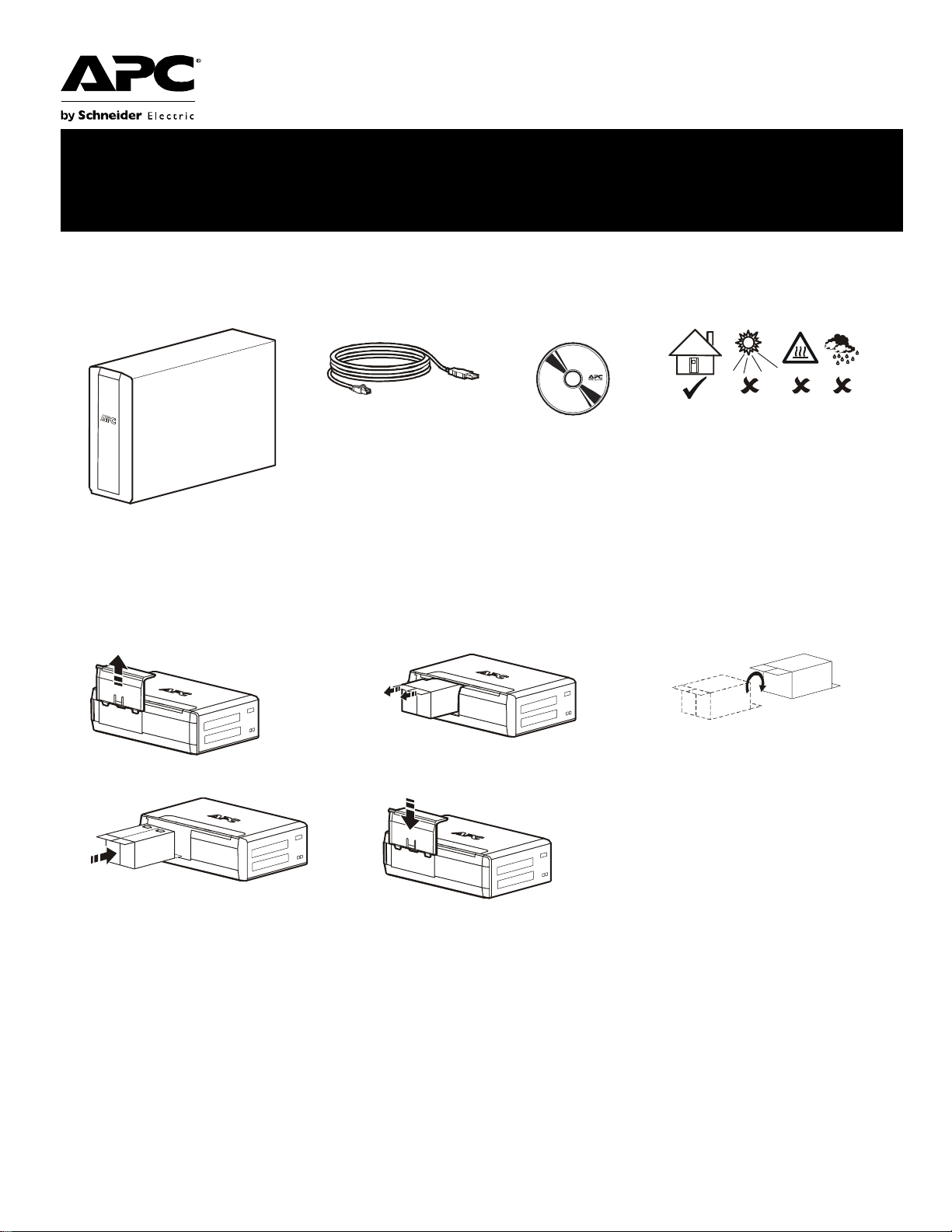
Inventory Safety
BR1200G-GR/BR1500G-GR
This unit is inten ded for indoor use only.
Do not operate this unit in di rect sunlight,
in contact with f lui ds, or where there is
excessive dust or humidity.
Connect the battery
123
bu059a
bu057a
bu055a
45
bu058a
bu060a
Charge the battery for at least 16
hours before use.
Page 2

PowerChute® Person al Edition Software
Overview
PowerChute Personal Edition Softwa re allows you to use your computer to access additional power pro tection and
management features of the Back-UPS.
Using PowerChute, you can:
• Preserve work in progress during a power outage by putting your computer into Hibernate mode. When the power
returns, the computer will appear exactly as it did before the power outage.
• Configure the Back-UPS management features, such as power-saving outlets, shutdown parameters, audible alarms, and
more.
• Monitor and view the status of the Back-UPS, including the estimated runtime, power consumption, power event hist ory,
and more.
A vailable features will vary by Back-UPS model and operating system.
If you choose not to install PowerChute, the Back-UPS will still provide backup power and power protection to
connected equipment. However, you will only be able to configure a limited number of features using the display
interface.
Compatibility
PowerChute is compatibl e with Windows o pera ting systems only. For a detailed list of supp orted operating systems,
go to www.apc.com, sele ct Software & Firmware.
For Mac operating systems, we recommend using the nativ e shutdown application (within System Preferences)
which recognizes your battery backup and allows you to configure shutdown of your system during power outages.
To access this application, connect a USB cable from the Back-UPS
on your computer, and see the documentation provided with your computer.
DATA PORT (POWERCHUTE PORT) to a USB port
Installation
Connect the Back-UPS to a computer using a USB cable. Plug one end into the POWERCHUTE PORT on the rear panel
of the Back-UPS and the other into a USB port on your computer.
Insert the PowerChute CD into your co mputer and foll ow the on-scre en instr uctions. If your Back-UPS di d not come
with a PowerChute CD, download the software from www.apc.com, sele ct Software & Firmware.
Connect the equipment
Battery Backup and Surge Protected outlets
When the Back-UPS is receiving input power, the Surge Protection only outlets and the Battery Backup with Surge
Protection outlets will supply power to connected equipment. During a power outage or other utility problems, only
the Battery Backup outlets receive power for a limited time from the Back-UPS.
Connect equipment such as printers, FAX machines, scanners, or other peripherals that do not need battery backup
power to the Surge Protectio n Only outlets. These outlets provide full tim e protection from surges even if the
Back-UPS is switched off.
Master and Controlled outlets
To conserve electricity, when the device connected to Master Outlet goes into Sleep or Standby mode, or turns off,
the Controlled by Master device(s) will shut down as well, saving electricity.
Connect a master device, such as a desktop computer or audio/visual receiver to the Master outlet. Connect
peripheral devices such as a printer, speakers, or a scanne r to the Controlled by Master outlets.
Back-UPS BR1200G-GR/BR1500G-GR Installation and Operation2
Page 3
bu219a
Backup
Surge
Only
TVSS
GND
Circuit Breaker
Push to Reset
bu218a
Backup
Surge
Only
TVSS
GND
Circuit Breaker
Push to Reset
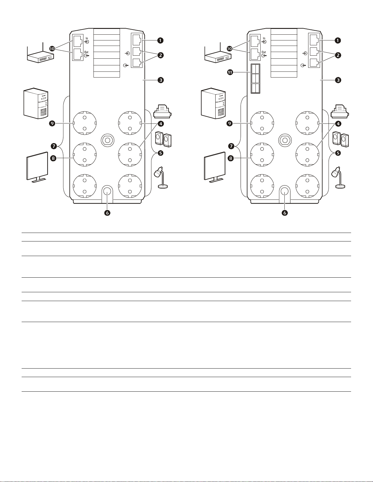
BR1200G-GR
BR1500G-GR
Battery
MASTER
Controlled by MASTER
USB &
Serial
Tel In
Tel O ut
Controlled by MASTER
Controlled by MASTER
Battery
MASTER
Controlled by MASTER
USB &
Serial
Tel In
Tel O ut
Controlled by MASTER
Controlled by MASTER
USB and Serial Data port To use PowerChute Pers onal Edition, connect the supplied USB software cable or serial cable.
1
T elephone ports Connect a telephone cable to the In port, and a modem to the Out port.
2
Ground screw Connect the ground wire fr om another surge suppressi on device such as a network or data li ne
3
surge protecto r to the ground screw on the Back-UPS.
Surge Protection outlets,
4
Controlled by Master outlet
These outlets provide surge protection during a power outage. These outlets will disconnect
from A/C power during a power out age, or in the event that the Master out let goes into Sleep
mode.
Surge Protection outlets These outlets provide full-time surge protection, when the unit is turned on or off. Connect a
5
printer, scanner or other devices that do not require batt ery backup protectio n.
AC Power Cable Connect t he Back-UPS to A/C power.
6
Battery Backup outlets with
7
Surge Protection
During a power outage or othe r utility problems, these outlets provide power from the
Back-UPS battery. Connect critical equipment such as desktop computer, computer monit or,
modem or other data sensitive devices to these outlets.
Battery Backup, Controlled by
8
Master outlet with Surge
Protection
During a power outage or othe r utility problems, these outlets provide power from the
Back-UPS battery.
These outlets will disconnect from A/C power during a power outage, or in the event that the
Master outlet goe s int o Sleep mode.
Connect critical equipment such as desktop com puter, computer monitor , modem or other data
sensitive devices to these outlets.
Master outlet Connect the master devi ce to this outlet, in most scenarios, this will be the main computer.
9
Gigabit Ethernet
:
Use an Ethernet cable to connect a modem to the IN port, and a computer to the OUT port.
surge-protected ports
External Battery Pack connector
;
Connect an external batt ery pack to provide addi ti onal battery backup ru nti m e.
BR1500G-GR model only
Back-UPS BR1200G-GR/BR1500G-GR Installation and Operation
3
Page 4

Operation
Power-Saving Function
To conserve electricity, configure the Back-UPS to recognize a Master device, such as a desktop
computer or an A/V re ceiver, and Controlled peripheral devices, such as a printer , speakers, or a scanner.
When the Master device goes into Sleep or Standby mode, or is switched OFF, the Controlled device(s)
will be switched off as well, saving electricity.
Enable the Power-Saving function. P ress a nd hold MUTE and DISPLAY simultaneously for two seconds. The
Back-UPS will beep to indicate that the feature is enabled. The leaf icon on the display will ill uminate.
Disable the Power-Saving function. Press and hold MUTE and DISPLAY simultaneously for two seconds. The
Back-UPS will beep to indicate that the feature is disabled. The leaf icon on the display will go dark.
Setting the threshold. The amount of power used by a devic e in Sleep or S ta ndby mode varies betwe en devices. It
may be necessary to adjust the threshold at which the Master outlet signals the Controlled outlets to shut down.
1. Ensure a master device is connected to the Master outlet. Put that device into Sleep or Standby mode, or turn it
OFF.
2. Press DISPLAY and MUTE simultaneously and hold for six seconds, until the leaf icon flashes three times and the
Back-U PS beep s thre e tim es .
3. The Back-UPS will now recognize the threshold level of the Master device and save it as the new threshold
setting.
Power-Saving Display
The display interface can be configured to be continuously illuminated, or to save energy, it can be configured to go
dark after a period of inactivity.
1. Full Time Mod e: Press a nd hold
DISPLAY for two se conds. The displ ay will i llumina te and the Back- UPS will beep
to confirm the Full-Time mode.
2. Power-Saving Mode: Press and hold
DISPLAY for two seconds. The display will go dark and the Back-UPS will
beep to confirm the Power-Saving mode. While in Power-Saving Mode, the display will illuminate if a button is
pressed, it goes dark after 60 seconds of no activity.
Unit sensitivit y
Adjust the sensitivit y of the Back-UPS to control when it will switch to battery power; the higher the sensitivity, the
more often the Back-UPS will switch to batter y power.
1. Ensure the Back-UPS is connected to A/C power, but is OFF.
2. Press and hold the POWER button for six seconds. The LOAD CAPACITY bar will flash on and off, indicating that the
Back-UPS is in programming mode.
3. Press
POWER again to rotate through the menu options. Stop at selected sensitivity. The Back-UPS will beep to
confirm the selection.
Low sensitivity Medium sensitivity (Default) High sensitivity
156-300 Vac 176-294 Vac 176-288 Vac
Input voltage is extremely low or
high. (Not recommended for
computers.)
Back-UPS BR1200G-GR/BR1500G-GR Installation and Operation4
The Back-UPS frequently swi tches to
battery power.
The connected equipment is
sensitive to voltage fluctuations.
Page 5

Front Panel Buttons and Display Interface
bu044a
bu002a
Use the three buttons on the front panel of the Back-UPS and the display interface to configure the Back-UPS.
Front panel
Mute button
1
Power O n /O ff button
2
Display button
3
Display inter face
4
On Line—The Back-UPS is suppl ying conditioned A/C power to con nected equipment
Power-Saving—Master and Controlled outlets are enabled, saving power when the master devi ce goes into
sleep or standby mode
Load Capacity—The load is indicated by the number of sections illuminat ed, one to five. Each bar repres ents
20% of the load.
Battery Charge—The battery charge level is indi cated by the number of secti ons illuminated. When all f ive
blocks are illumin ated, th e Back-UPS is at full char ge. When one block is fille d, the Back- UPS is near the end of
its battery capacity, the indicator will flash and the Back-UPS will beep continuously.
Overload—The power demand from the load has exceeded the capacity of the Back-UPS.
Event—The event counter shows the number of events that occurred that caused the Back-UPS to switch to
on-battery operation.
Automatic Voltage Regulation—The Back- UPS can com pensate for high or low input volt age.
When illuminat ed, the Back-UPS is compensating for low input voltage.
When illuminat ed, the Back-UPS is compensating for high input voltage .
Input volta ge.
Output voltag e.
System Faults—The system has a fault. The fault number will illuminate on the display interface.
See “System Faults” on page 6.
Mute—If the line through the spea ker icon is illuminated, th e audible alarm has been turned off.
Replace Battery—The batt ery is not connected or is nearing the end of its useful li fe. Replace the battery.
On Batte ry—The Back-UPS is supplying battery bac kup power to the connected equipment, it will beep four
times every 30 seconds.
Back-UPS BR1200G-GR/BR1500G-GR Installation and Operation
5
Page 6

Warnings and System Faults
bu088
a
Audible Warnings
Four Beeps Every 30 Seconds
Continuous Beeping
Continuous tone
Chirps fo r 1 Mi n ut e ev e ry 5 hours
Warning Icons
If these icons are
illuminated... This may be the problem.
The Back-UPS is operating on A/C power, but is overloaded. Disconnect one of the items
connected to the Back- UPS. If the Overload icon stops fl ashing, the Back-UPS is no longer
overloaded and will cont inue to operate normally.
The Back-UPS is operating on battery power , but is overloaded. Disconnect one of the items
connected to the Back- UPS. If the Overload icon stops fl ashing, the Back-UPS is no longer
overloaded and will cont inue to operate normally.
The Back-UPS is operating on A/C power, but the battery is not functioning properl y. Contact APC
Customer Service to order a replacement battery. See “Replacement Batter y” on page 8.
Back-UPS is running on battery. Y ou should consider savi ng any work in progress.
Low battery conditi on and ba ttery run- time i s very low. Promptly save any work in progress, exit
all open applicati ons, and shut down the operating system.
Battery Backup outp uts are overloaded.
Battery fails th e automatic diagnosti c test and should be replaced.
The Back-UPS is operating on battery power and the battery power is gett ing low. Shut down all
connected equipment to avoid losing unsaved data. When possible, conn ect the Back-UPS to A/C
power to recharge the battery.
System Faults
The Back-UPS will display these fault messages. Contact APC Technical Support.
On-Battery Over load Turn the Back-UPS off. Disconnect non-essential
F01
On-Battery Outp ut Short Turn the Back-UPS off. Disconnect non-essential
F02
On-Battery Xcap Over load
F03
Clamp Short
F04
Charge Fault
F05
Relay Welding
F06
Temperature
F07
Fan Fault
F08
Internal Fault
F09
equipment from the Batt ery Backup outlets and the tur n
Back-UPS on.
equipment from the Batt ery Backup outlets and the tur n
Back-UPS on.
Faults F03-F09 cannot be corrected by the user. Contact
APC Technical Support for assist ance.
Back-UPS BR1200G-GR/BR1500G-GR Installation and Operation6
Page 7

Function Button Quick-Reference
Function Button
Power
Power On
Power Off
Display
Status Inquiry
Full-Time/PowerSaving mode
Mute
Event Specific
General Status Enable/
Disable
Timing
(seconds)
UPS
Status
0.2 Off
2On
0.2 On
2On
0.2 On
2On
Description
Press POWER to start receiving input A/C power. If A/C input
power is not available, the Back-UPS will run on battery power.
The Back-UPS is not receiving input A/C power, but is providing
surge protection.
Verify the status or condition of the Back-UPS. The LCD will
illuminate for 60 seconds.
The LCD will illuminate and the Back-UPS will beep to confirm the
Full-T ime mode. The LCD will go dark and the Back-UPS will beep
to confirm the Power-Saving mode. Whil e in Power-Saving Mode,
the LCD will illuminate if a button is pressed, then goes dark after
60 seconds of no activity.
Disable any audible alarms caused by an event.
Enable or disable the audible alar ms. The Mut e icon will ill uminat e
and the Back-UPS will beep one time. The Mute function will not
activate unless the Back-UPS is operating on battery power.
Sensitivity
Master/Controlled
outlet Enable/Disable
Master/Enable
Threshold Calibration
Self-Test (manual)
Event Reset
Fault Reset
6Off
2On
6On
6On
0.2 On
2Fault
The Load Capacity i con wi ll bli nk, indicating that the Back-UPS is
in programming mode. Use the P
Low, Medium, and High, stop at selected sensitivity. The BackUPS will beep to confirm selection. See Configuration for details.
The leaf icon will go dark indicating that the Mast er Outlet feature
is disabled or il luminate to indicate the Mast er Outlet feature is
enabled. The Back-UPS will beep once.
While cali brati ng the thres hol d sett ing, the de vi ce connec ted to t he
Master Outlet should be turned off or placed in Standby or Sleep
mode. Upon completi on, Power-Saving icon will fl ash 3 times and
beep 3 times.
The Back-UPS wil l perf orm a t est of the i nternal batt ery. Note: This
will happen automati cally when the Back-UPS is turned ON.
When the Event screen is visible, press and hold DISPLAY, then
press
After a fault has been identified, press POWER to remove the
visual indication and return to standby status.
OWER button to scroll through
POWER, to clear the utility failure event counter.
Back-UPS BR1200G-GR/BR1500G-GR Installation and Operation
7
Page 8

Troubleshooting
Problem Possible C ause Corrective Action
Back-UPS will not turn on. The Back-UPS is not conne cted to A/C
power.
The circuit breaker has been tripped. Disconnect non-essential equipment from the
The interna l battery is not connected. Connect the bat tery.
The A/C input voltage is out of range. Adjust the transfer voltage and sensitivity range.
The Bac k- U PS d o es no t
provide power during a A/C
power outage.
The Back-UPS is operating on
battery power, while connected
to A/C power.
The Bac k- U PS d o es no t
prov ide the exp ecte d amount of
backup time.
The
REPLACE BATTERY
indicator is illuminated.
The
OVERLOAD indica t o r is
illuminated.
The
SYSTEM FAULT indicator is
illuminated, all the front panel
indica tors are flashing.
Power is not supplied to some
outlets.
The Con t rolle d out l et s a re not
supplying power, even though
the Master device is not in sleep
mode.
Ensure that essential equipment is not
plugged into a
The plug has parti ally pulled out of the wall
outlet, the wall outlet is no longer receiving
A/C power, or the circuit breaker has been
tripped.
The Back-UPS is per f orm ing an automatic
self test.
The A/C input voltage is out of range, the
frequency is out of range, or the waveform
is distorted.
Battery Backup outlets may be fully or
improperly loa ded.
The battery was recently discharged due to a
power outage and has not fully recharged.
The battery has reached the end of its useful
life.
The battery has reached the end of its useful
life.
The equipment connected to the Back-UPS
is drawi ng mo r e p ow e r th an the Back-U PS
can pr ovid e.
There is an internal fault. Determine which internal fau lt message is
Power to the Controlled outlets has
intentionally been turned off.
The Master Outlet threshold may be
incorrectly set.
SURGE ONLY outlet.
Ensure that the Back-UPS is secure ly connec ted
to an A/C outle t.
Back-UPS. Rese t the circuit br eaker . Re -connect
equipment one item at a time. If the circuit
breaker is tripped again, disconnect the device
that ca us ed th e tr i p.
Disconnect equipment from the
outlet and re-connect to a Batte r y Backup outlet.
Ensure that the plug is fully inserted into the
wall outlet. Ensure that the wall outlet is
receiving A/C powe r by checking it with
another device.
No action is necess ary.
Adjust the transfer voltage and sensitivity range.
Disconnect non-essential equipment from the
Battery Backup outlets and connect the
equipment to
Charge the battery cartridge for 16 hours.
Replace the battery.
Replace the battery.
Disconnect non-essential equipment from the
Battery Backup outlets and connect the
equipment to
displayed by matching the number displa yed on
the LCD with the corresponding Fault Message
(see System Faults) and contact APC Technical
Support.
Confirm that the correct peripherals are
connected to Controlle d outlets. If this fea ture is
not desired, dis able the Power-Saving Master
and Controlled outlets.
Adjust the threshold when the Master outlet
signals the Controlled outlets to shut down.
SURGE ONLY outlets.
SURGE ONLY outlets.
SURGE ONLY
Back-UPS BR1200G-GR/BR1500G-GR Installation and Operation8
Page 9

Specifications
t
Model BR1200G-GR BR1500G-GR
VA 1200 VA 1500 VA
Maximum Load 720 W 865 W
Nominal Input Voltage 230 V
Online Input Voltage Range 176 V- 294 V
Automatic Voltage Regulation 188 V- 216 V +11.2%
252 V- 282 V -11.2%
Frequency Range 50/60 Hz ± 1 Hz
On-battery wave shape Step-approximated sine-wave
Typical Recharge Ti m e 8 hours
Transfer Time 10 ms, maximum
º
Operating Temperature 0
Stora ge Temperature 5
Unit Dimensions 30.1 × 11.2 × 39 cm (11.9 × 4.4 × 15.3 in)
Unit Weight 12.8 kg (28.2 lbs) 13.4 kg (29 .5 lbs)
Interface Serial, USB
On-Bat tery Runtime Go to: www.apc.com
Replacement Battery The battery ca rtridge typ ically lasts 3 to 6 years. Environmental factors impa ct
to 40º C (32º to 104º F)
º
to 45º C (23º to 113º F)
battery life. High temperatures, poor quality A/C power, and frequent, short
deration discharg es w ill shorten battery life. To order replacement battery
cartridge APCRBC124, refer to the APC Web site, www.apc.com.
Recycle used battery cartridges.
APC Customer Support
Intern et w ww.a pc. com
Telephone +1 888 272 3858
W arranty
The standard warranty is two (2) years from the date of purchase. APC standard procedure is to replace the original
unit with a factory recondi tioned unit. Customers who must have the original unit back due to the assignment of asset
tags and set depreciation schedules must declare such a need at first contact with an APC Technical Support
representative. APC wil l ship the re placement unit onc e the defectiv e unit has been rec eived by the repair de part ment,
or cross-ship upon the receipt of a valid credit card number. The customer pays for shipping the unit to APC. APC
pays ground freight transpor tation costs to ship the replacement unit to the cus tomer.
Back-UPS BR1200G-GR/BR1500G-GR Installation and Operation
9
Page 10

Service
If the unit requires service, do not return it to the dealer. Follow these steps:
1. Review the
TROUBLESHOOTING section of the manual to eliminate common problems.
2. If the problem persists, cont act APC Customer Suppor t through the APC Web site, www.apc.com.
a. Note the model number and serial number and the date of purchase . The model and
serial numbers are located on the rear panel of the unit and are available through the
LCD display on select models.
b. C all APC Customer Support and a technician will attempt to solve the problem over the
phone. If this is not possible, the technician will issue a Returned Material
Authorization Number (RMA#).
c. If the unit is under warranty, the repairs are free.
d. S ervice proce dures and returns may vary inte rnationa lly. Refer to the APC Web sit e for
country specific ins tructions.
3. Pack the unit properly to avoid damage in transit. Never use foam beads for packaging. Damage
sustained in transit is not covered under warranty. For the UPS, always DISCONNECT THE
BATTERY before shipping in compliance with U.S. Department of Transportation (DOT)
and IATA regulations. The batter y may remain in the unit.
4. Write the RMA# provided by Cust omer Support on the outside of the package.
5. Return the unit by insured, pre-paid car rier to the address provided by Customer Support.
© 2010 APC by Schneider Electric. A PC, the APC logo, Back-U PS and PowerChute a re
owned by Schneider Electric Industries S.A.S., American Power Convers ion Corporati on, or
their affiliated companies. All other trademarks are property of their respective owners.
990-3973A
03/2011
 Loading...