

Page 1
Back-UPS® Pro 1200/1500 230V
Installation and Operation
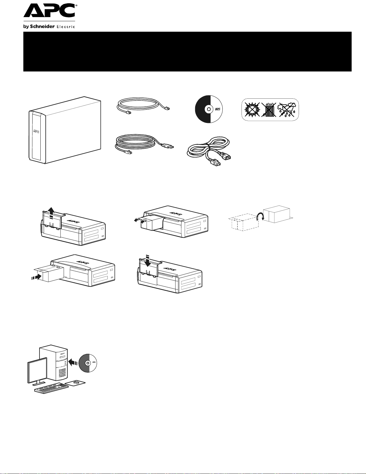
Inventory Safety
(2)
bu001a
Do not install the Back-UPS in direct
sunlight, in excessive heat, humidity, or
in contact with fluids.
Connect the battery
bu059a
bu057a
bu055a
bu058a
bu060a
Install PowerChute
APC PowerChute Personal Edition sof tware provides automatic file saving and shutdown of
your computer in the event of a power failure. Use the cable supplied with the Back-UPS to
connect the data port on the Back-UPS to the USB port on your computer. Place the CD into
your computer, and follow the on-screen instructions.
®
Personal Edition Software
Page 2
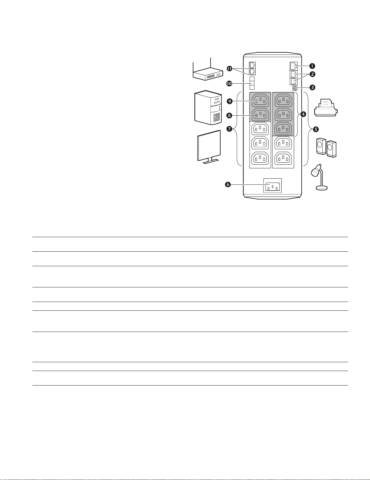
Connect the equipment
Battery Backup and Surge Protected outlets
When the Back-UPS is receiving input power, the
Battery Backup with Surge Protection outlets will
supply power to connected equipment. During a
power outage or other utility probl ems, the Batte ry
Backup outlets receive powe r for a limited time from
the Back-UPS.
Connect equipment such as printers, fax machines,
scanners, or other peripherals that do not need
battery backup power to the Surge Protection Only
outlets. These outlets provide full-time protection
from surges ev en if the Back-U P S i s switch e d OFF.
Master and Controlled outlets
To conserve electricity, when the device connected
to Master Outlet goes into Sleep or Standby mode, or
turns Off, the Controlle d devic e(s) will shu t down as
well, saving electricity.
Connect a master device, such as a desktop
computer or audio/visual rec eiv er to the Master
outlet. Connect peripheral devices such as a printer, spe akers, or a scanner to the Controlled outlets.
bu146a
USB and Serial Data port To use PowerChute Personal Edition, connect a serial cable or USB cable.
Telephone cable surge-
protected ports
Ground screw Connect the ground lead of additi onal s urge supp res sion devi ces suc h as n etwork an d dat a line
Surge Protected outlets,
controlled by the Master
outlet
Surge Protected outlets These outlets provide full-time protection from surges, even if the Back-UPS is off. Connect
AC power outlet Connect the unit to utility power, use the supplied power cord.
Battery Backup outlets with
Surge Protection
Battery Backup outlet wit h
Surge Protection, contr olled
by the Master outlet
Master outlet Connect the master device to this outlet, in most scenarios, this will be the main computer.
External Batter y Pack
connector (BR1500GI onl y)
In & Out Ethernet surge-
protected ports
Connect a telephone cable to t he IN port, and connect a modem to the OUT port.
surge protectors.
These outlets are protected from electrical surges, and will disconnect from utility power during
a power outage, or if the Mast er device goes into Sleep or S tandby mode.
equipment such as printers and scanners that do not requi re battery backup protection.
During a power out age or other utility problems, the Battery Backup outlets receive power for a
limited time from the Bac k-UPS. Connect critical equipment such as desktop computer,
computer monitor, modem or other data sensitive devices into these outlets.
These outlets will supply battery power to the connected equipment during a power outage.
Power will be disconnect ed to th ese outlets if the Master device goes into Sleep or Standby
mode. Connect equipment such as a computer monitor to these outlets.
Connect an external batt ery pack to provide additional battery backup runtime (Back-UPS Pro
1500 only).
Use an ethernet cable to connect a cable modem to the IN port, and connect a computer to the
O
UT port.
Back-UPS Pro 1200 & 1500 230 V Installati on and O peration2
Page 3

Operation
Power-Saving Function
T o conserve electricity, configur e the Back-UP S to recognize a Master device, such as a desktop
computer or an A/V receiver, and Controlled peripheral devices, such as a printer, speakers, or a scanner.
When the Master device goes into Sleep or Standby mode, or is switched OFF, the Controlled device(s)
will be switched off as well, saving electricity.
Enable the Power-Saving function. Press and hold MUTE and DISPLAY simultaneously for two seconds. The
Back-UPS will beep to indicate that the feature is enabled. The leaf icon on the display will illumin ate.
Disable t he Power-Saving function. Press and hold MUTE and DISPLAY simultaneously for two seconds. The
Back-UPS will beep to indicate that the feature is disabled. The leaf icon on the display will darken.
Setting the threshold. The amount of power used by a device in Sleep or Standby mode vari es between devices. It
may be necessary to adjust the threshold at which the Master outlet signals the Controlled outlets to shut down.
1. Ensure a master device is connected to the Master outlet. Put that device into Sleep or Standb y mode, or turn it
OFF.
2. Press
DISPLAY and MUTE simultaneously and hold for six seconds, until the leaf icon flashes three times and the
Back-UPS beeps three times.
3. The Back-UPS will now recognize the threshold level of the Master device a nd save it as the new threshold set ting.
Power-Saving Display
The display interface can be configured to be continuously illuminated, or to save energy, it can be configured to
darken after a period of inactivity.
1. Full Tim e Mode: Press and hold
DISPLAY for two seconds. The display will illumi nate and the Back-UPS will beep
to confirm the Full-Time mode.
2. Power-Saving Mode: Press a nd hold
DISPLAY for two seconds. The display will darken and the Back-UPS will
beep to confirm the Power-Saving mode. While in Power-Saving Mode, the display will illuminate if a button is
pressed, it then darkens after 60 seconds of no activity.
Unit sensitivity
Adjust the sensitivity of the Back-UPS to control when it will switch to battery power; the higher the sensitivity, the
more often the Back-UPS will switch to batter y power.
1. Ensure the Back-UPS is connected to utility power, but is OFF.
2. Press and hold the POWER button for six seconds. The LOAD CAPACITY bar will flash on and off, indicating that the
Back-UPS is in programming mode.
3. Press
POWER again to rotate through the menu options. Stop at selected sensitivity. The Back-UPS will beep to
confirm the selection.
Low sensitivity Medium sensitivity (Default) High sensitivity
156-300 Vac 176-294 Vac 176-288 Vac
Input voltage is extremely low or high. (Not recom me nded for computer loads. )
Back-UPS Pro 1200 & 1500 230 V Installation and Operation
The Back-UPS frequently switches to battery power.
The connected equipment is sensitive to vol tage fluctuations .
3
Page 4

Front Panel Buttons and Display Interface
Use the three buttons on the front panel of the Back-UPS and the display interface to configure the Back-UPS.
Fro nt panel
Mute button
Power On/Off button
Display button
Display interface
bu002a
bu044a
On Line—The Back-UPS is supplying conditioned utility power to connected equipment
Power-Saving—Master and Co ntrolled outlets are enabled, saving power when the master d evice goes into
sleep or standby mode
Load Capacity—The load is indicated by the number of sections illuminated, one to five. Each bar repr esents
20% of the load.
Battery Charge—The battery charge level is indicated by the number of sections il luminated. When all five
blocks are illumi nated, the Back-UPS is at full charg e. When one block i s filled, the Back-UPS i s near the end of
its battery capacity, the indicator will flash and the Back-UPS will beep continuously.
Overload—The power demand from the load has exceeded the capacity of the Back-UPS.
Event—The event counter shows the number of events that occurred that caused the Back-UPS to swit ch to
on-b atter y oper ation .
Automatic Voltage Regul ation—The Back-UPS can compensate fo r high or low input voltage.
When illuminated, th e Back-UPS is compensating for low input voltage.
When illuminated, the Back-UPS is compensating for high input voltage.
Input volt age.
Output volt age.
System Faults—The system has a fault. The fault number wil l i lluminate on the displ ay interface. See “System
Faults” on p age5.
Mute—If the line through the speaker ic on is illuminated, the audibl e alarm has been turned off.
Replace Battery—The battery is not connected or is nearing the end of its useful life. Replace the battery.
On Battery—The Back-UPS is supplying battery backup power to the connected equipment, i t will beep four
times every 30 seconds.
Back-UPS Pro 1200 & 1500 230 V Installati on and O peration4
Page 5

Warnings and System Faults
bu088
a
Audible Warnings
Four Beeps Every 30 Se conds
Continuous Beeping
Continuous to ne
Chirps f o r 1 Mi n ut e ev er y 5 hours
Warning Icons
If these icons are
illuminat ed... This may be the problem.
The Back-UPS is operating on utility power, but is overloaded. Disconnect one of the items
connected to the Back- UPS. If the Overload icon stops flashing, the Back-UPS is no longer
overloaded and will cont inue to operate normally.
The Back-UPS is operating on battery power, but is overloaded. Disconnect one of th e it em s
connected to the Back- UPS. If the Overload icon stops flashing, the Back-UPS is no longer
overloaded and will cont inue to operate normally.
The Back-UPS is operating on utilit y power, but the batter y is not f unctio ning prop erly. Cont act APC
Customer Service to order a replacement battery. See “Replacement Battery” on page 8.
Back-UPS is running on battery. You should consider saving any work in pr ogress.
Low battery conditi on and b attery run- time i s very lo w . Pro mptly sav e any wor k in progress, exit
all open applicati ons, and shut down the operating sys tem.
Battery Backup out puts are overloaded.
Battery fails th e automatic diagnostic test and should be replaced.
The Back-UPS is operating on bat tery power and the battery power is getti ng low. Shut down all
connected equipment to avoid losing an unsaved dat a. When possible, connect the Back-UPS to
utility power to recharge the batter.
System Faults
The Back-UPS will display these fault messages. For faults F01 and F02, contact APC Technical Support.
On-Battery Overload Turn the Back-UPS off. Disconnect non-essential
F01
On-Battery Output Short Turn the Back-UPS off. Disconnect non-essential
F02
On-Battery Xcap Overload
F03
Clamp Sh o rt
F04
Charge Fault
F05
Relay Welding
F06
Temperature
F07
Fan Fault
F08
Internal Fault
F09
equipment from the Battery Backup outlets and the turn
Back-UPS on.
equipment from the Battery Backup outlets and the turn
Back-UPS on.
Faults F03-F09 cannot be corrected by the user, contact APC Technical Support for assistance.
Back-UPS Pro 1200 & 1500 230 V Installation and Operation
5
Page 6

Function Button Quick-Reference
Function Button
Power
Power On
Power Off
Display
St atus Inquiry
Full-Time/PowerSaving mode
Mute
Event Specific
General Status Enable/ Disable
Timing
(seconds)
UPS
Status
0.2 Off
2On
0.2 On
2On
0.2 On
2On
Description
Press POWER to start rec eiving input utility power. If A/C input
power is not available, the Back-UPS will run on battery power.
The Back-UPS is not receivi ng input utility power, but is providing surge protection.
Verif y the status or condition of the Back-UPS. The LCD will illuminate for 60 seconds.
The LCD will illuminate and the Back-UPS will beep to confirm the
Full-Time m ode. The LCD will darken and the Back-UPS wil l beep
to confirm the Power- Saving mode. While in Power- Saving Mode,
the LCD will illuminat e if a butto n is press ed, then darkens af ter 60
seconds of no activity.
Disable any audible alarms caused by an event.
Enable or disable the audi ble ala rms. The Mute i con will ill umina te
and the Back-UPS will beep one time. The Mute function will not
activate unless the Back-UPS is operating on battery power.
Sensitivity
Master/Controlled outlet Enable/Disable
Master/Enable Threshold Calibration
Self-Test (man ual)
Event Reset
Fault Reset
6Off
2On
6On
6On
0.2 On
2Fault
The Load Capacity icon will blink, indica tin g th at the B ac k -UP S is
in programming mode. Use the P
Low, Med ium, and High, stop at selected sensitivity. The BackUPS will beep to confirm select ion. See Configuration for details.
The leaf icon will darken indi cating that the Master Outl et feature is
disabled or illumi nate to indicate the Master Outlet feature is
enabled. The Back-UPS will beep once.
While calibrati ng the threshold setting, the device connect ed to the
Master Outlet should be turned off or placed in Standby or Sleep
mode. Upon completion, Power-Saving icon will flash 3 and beep
3 times.
The Back-UPS will per form a tes t of the i nter nal bat tery. Not e: Thi s
will happen automatically when the Back-UPS is turned ON.
When the Event screen is vi sible, press and hold DISPLAY, then
press
After a fault has been iden ti fi ed, press POWER to remove the
visual indicati on and return to standby status.
OWER button to scroll through
POWER, to clear the utility failure event counter.
Back-UPS Pro 1200 & 1500 230 V Installati on and O peration6
Page 7

Troubleshooting
Problem Possible Cause Corrective Action
Back-UPS will not switch on. T he Back-UPS is not connecte d to utility
power.
The circuit brea ker has been tripped. Disconnect non-essential equipment from the
The internal battery is not connected. Connect the battery.
The utility input voltage is out of range. Adjust the transfer voltage and sensitivity range.
The Back-U PS does not
provide power during a utility
power outage.
The Back-UPS is operatin g on
battery power, while connected
to utility power.
The Back-U PS does not
provide the expected amount of
backup time.
The
REPLACE BATTERY
indicator is illuminated.
The O
VERLOAD indicator is
illuminated.
The
SYSTEM FAULT indica tor is
illuminated, all the front panel
indicators are flashing.
Power is not supplied to some
outlets.
The Con trol l ed ou tl ets are not
supplying power, even though
the Mast er devi ce is no t in slee p
mode.
Ensur e th at essen t ial equip ment is not
plugged into a
The plug has parti ally pulled out of the wall
outlet, the wall outlet is no longer recei ving
utility power, or the circuit brea ker has been
tripped.
The Back-UPS is perf ormi ng an automatic
self test.
The utility input voltage is out of range, the
frequency is out of range, or th e waveform
is distorted.
Battery Backup outlets may be fully or
improperly loaded.
The battery wa s recent ly disc harge d du e to a
power outage and has not fully recharged.
The battery has reached the en d of its useful
life.
The battery has reached the en d of its useful
life.
The equipme nt connected to the Back-UPS
is drawi n g mo r e p o w er th an th e B ac k- U PS
can provide.
There is an internal fault. Determine which internal fault message is
Power to the Controlled outlets has
intentionally been turned off.
The Master Outlet threshold may be
incorrectly set.
SURGE ONLY outlet.
Ensure that the Back-UPS is secur ely connected
to an AC outlet.
Back-UPS. Rese t the circui t breaker. Re-connec t
equipment on e it em at a time . If th e ci r cu i t
breaker is tripped again, disconnect the device
that cau s ed th e tr i p .
Disconnect equi pme nt from the
outlet and re-c onnect to a Battery Bac kup outlet.
Ensur e that the plug is f ully ins e r ted into th e
wall outle t. Ensure that th e w all outlet is
receiving utility power by checking it with
another device.
No action is necessary.
Adjust the transfer voltage and sensitivity range.
Disconnect non-essential equipment from the
Battery Backup outlets and connect the
equipment to
Charge the battery cartridge for 16 hours.
Replace the battery.
Replace the battery.
Disconnect non-essential equipment from the
Battery Backup outlets and connect the
equipment to
displayed by mat ching the number displayed on
the LCD with the corresponding Fault Message
(see System Faults) and contact APC Technical
Support.
Confirm that the correct p eripherals are
connected to Controlled outlets. If this feature is
not desired, disable the Power-Saving Master
and Controlled outlets.
Adjust the threshold when the Master outlet
signals the Controlled outlets to s hut down.
SURGE ONLY outlets.
SURGE ONLY outlets.
SURGE ONLY
Back-UPS Pro 1200 & 1500 230 V Installation and Operation
7
Page 8

Specifications
t
Model BR1200GI BR1500GI
VA 1200 VA 1500 VA Maximum Load 720 W 865 W Nominal Inpu t Voltage 230 V Online Inp ut Voltage Range 176 - 294 V Automatic Voltage Regulation (188-216) +11.2%
(252-282) -11.2% Frequency Range 50/60 Hz ± 1 Hz On-battery Waveshape Step-approximated sine-wave Typical Recharge Time 8 hour s Transfer Time 10 ms, maximum Operating Temperature 0 Storag e Temperature -15 Unit Dimensions 30.1 × 11.2 × 38.2 cm (11.9 × 4.4 × 15.0 in) Unit Weight 12.8 kg (28 .2 lbs) 13.4 kg (29.5 lbs) Interface Serial, USB On-Battery Runt im e Go to: www.apc.c om
to 40C (32 to 104F)
to 45C (23 to 113F)
Replacement Battery
The battery cartridge typically lasts 3 to 6 years, a shorter
period if subjected to frequent outages or elevate d
temperatures. Battery replacement part for Back-UPS Pro 1200
and 1500 is APCRBC124. Please recycle spent battery
cartridges.
Service
If the Back-UPS arrived damaged, notify the carrier.
If the Back-UPS requires service, do not return it to the dealer.
1. Consult the Troubleshooting section to elim inate common
problems.
2. If the problem persists, go to http://www.apc.com/support/.
3. If the problem still persists, contact APC Technical Support.
Have the Back-UPS model number, serial number and date of
purchase available. Be prepared to troubleshoot the proble m
with an APC Technical Suppo rt representative.
If this is not s uccessful, APC will is sue a Return Merchandise
Authorizati on (RMA) num ber an d a shipping address.
EMI Classification CE, C-Tick, KETI Approvals CE, TUV-GS, GOST, A-Tick, KETI, TISI
Warranty
The standard warranty is three (3) years from th e date of purchase, valid in European Community. For all other regions, the standard warranty
is two (2) yea rs from the date of purchase. APC’s standard procedure is to replace t he original unit wi th a factory reconditioned unit.
Customers w ho must have t h e original unit back due to the assignment of asset tags and set depreciation s chedules mus t declare such a need at
first contact with an APC Technic al Support representative. AP C will ship the replacement unit once the defective unit has been rece ive d by
the repair department, or cross-shi p upon the receipt of a valid credit card num ber. The customer pays for shipping the unit to APC. APC pays
ground fre ight transportation costs to ship the replacement unit to the customer
.
APC Worldwide Custom e r Support
Internet http://www.apc.com Worldwide +1 888 272-3858
Customer support and warranty inform ation is available at the APC Web site, www.apc.com.
© 03/2010 APC by Schneider Electric. All trademarks are owned by Schneider Electric Industries S.A.S., American
Power Convers ion Corporation, or their affiliated companies.
990-3889A
3/2010
 Loading...