

Page 1

Installation and Start-Up
®
InfraStruXure
For Medium Data Centers
40 kW 208/480/600 V
Page 2

About this Manual
This manual covers basic installation and start-up procedures for certified electricians, American Power
Conversion (APC
system.
For information about installing specific components in your InfraStruXure system, see the
documentation included with each component. Before installing or operating any component,
refer to the safety instructions in the component’s manual or safety sheet.
Note: The illustrations of products in this manual may vary slightly from the products in your
InfraStruXure system.
®
) Field Service Engineers, or APC-trained installers of a 40 kW InfraStruXure®
InfraStruXure System - Installation and Start-Up
Page 3

Contents
Safety................................................................................1
IMPORTANT SAFETY INSTRUCTIONS
- SAVE THESE INSTRUCTIONS . . . . . . . . . . . . . . . . . . . . . . . . . . . . . .1
Symbols used in this manual . . . . . . . . . . . . . . . . . . . . . . . . 1
Warnings . . . . . . . . . . . . . . . . . . . . . . . . . . . . . . . . . . . . . . . . . . . . . . . .2
Installation/Maintenance . . . . . . . . . . . . . . . . . . . . . . . . . . . 2
Maintenance performed while the PDU is receiving input power . 2
Total Power Off . . . . . . . . . . . . . . . . . . . . . . . . . . . . . . . . . 3
DANGER—Risk of Electric Shock! . . . . . . . . . . . . . . . . . . . . 4
Emergency Power Off (EPO) . . . . . . . . . . . . . . . . . . . . . . . . 4
EMI . . . . . . . . . . . . . . . . . . . . . . . . . . . . . . . . . . . . . . . . . 4
Site Planning....................................................................5
Space Considerations. . . . . . . . . . . . . . . . . . . . . . . . . . . . . . . . . . . . . .5
Installation Procedures...................................................7
Installation Procedure Overview . . . . . . . . . . . . . . . . . . . . . . . . . . . . .7
Tools Required . . . . . . . . . . . . . . . . . . . . . . . . . . . . . . . . . 9
Level the PDU, UPS, NetShelter, and XR Battery Enclosures. . . . .10
Exchange Side Panels . . . . . . . . . . . . . . . . . . . . . . . . . . . . . . . . . . . .11
Exchange Side Panels . . . . . . . . . . . . . . . . . . . . . . . . . . . 11
Connect Battery Enclosure communication cables . . . . . . . . 12
Join the PDU, UPS, and XR Battery Enclosures. . . . . . . . . . . . . . . .13
Connect Utility Conductors to the PDU. . . . . . . . . . . . . . . . . . . . . . .14
Access the PDU Main Input switch . . . . . . . . . . . . . . . . . . . 14
Attach conduit to the PDU for the input conductors . . . . . . . . 14
Install a circuit breaker . . . . . . . . . . . . . . . . . . . . . . . . . . . 15
Route the input conductors to the Main Input switch . . . . . . . 16
Connect input conductors . . . . . . . . . . . . . . . . . . . . . . . . . 16
Connect AC Power and Control Wiring. . . . . . . . . . . . . . . . . . . . . . .18
InfraStruXure System - Installation and Start-Up i
Page 4

Connect DC Power Wiring, if Applicable . . . . . . . . . . . . . . . . . . . . . 20
Cascade XR Battery Enclosures . . . . . . . . . . . . . . . . . . . . . 20
Connect power cables from the XR Battery Enclosure to the
Symmetra PX UPS
. . . . . . . . . . . . . . . . . . . . . . . . . . . . . . 21
Connect an Emergency Power Off Switch . . . . . . . . . . . . . . . . . . . . 22
Overview . . . . . . . . . . . . . . . . . . . . . . . . . . . . . . . . . . . . 22
Connect an EPO switch to the user connection plate . . . . . . . 23
Connect User Input Contacts and Relay Outputs to the
User Connection Plate . . . . . . . . . . . . . . . . . . . . . . . . . . . . . . . . . . . . 24
Overview . . . . . . . . . . . . . . . . . . . . . . . . . . . . . . . . . . . 24
Route and Attach Power Cables to the Racks . . . . . . . . . . . . . . . . . 25
Overhead Wiring . . . . . . . . . . . . . . . . . . . . . . . . . . . . . . . 25
Under Floor Wiring . . . . . . . . . . . . . . . . . . . . . . . . . . . . . 26
Route Data Cables to the InfraStruXure Manager Hub (or Switch) 28
Start-Up Procedure........................................................ 29
Apply power to the system . . . . . . . . . . . . . . . . . . . . . . . . . . . . . . . . 29
Safety warnings . . . . . . . . . . . . . . . . . . . . . . . . . . . . . . . 29
Verify UPS battery operation . . . . . . . . . . . . . . . . . . . . . . . 32
Verify proper voltage and phase rotation at the UPS . . . . . . . 34
Start the UPS . . . . . . . . . . . . . . . . . . . . . . . . . . . . . . . . . 34
Verify bypass operation . . . . . . . . . . . . . . . . . . . . . . . . . . 36
Power the PDU Distribution Breakers . . . . . . . . . . . . . . . . . 38
Configure the InfraStruXure Manager . . . . . . . . . . . . . . . . . 39
Specifications ................................................................ 41
40 kW InfraStruXure PDU. . . . . . . . . . . . . . . . . . . . . . . . . . . . . . . . . . 41
ii InfraStruXure System - Installation and Start-Up
Page 5
Safety
IMPORTANT SAFETY INSTRUCTIONS
- SAVE THESE INSTRUCTIONS
This manual contains important instructions that must be followed during installation, operation, and
maintenance of the InfraStruXure System.
Symbols used in this manual
Electrical Hazard: Indicates an electrical hazard which, if not avoided, could result in injury
or death.
Danger: Indicates a hazard which, if not avoided, could result in severe personal injury or
death.
Warning: Indicates a hazard which, if not avoided, could result in personal injury or
damage to product or other property.
Heavy: Indicates a heavy load that should not be lifted without assistance.
Caution: Indicates a potential hazard which, if not avoided, could result in damage to the
equipment or other property.
Tip Hazard: This equipment is easily tipped. Use extreme caution when unpacking or
moving.
Note: Indicates important information.
Indicates that more information is available on the same subject.
InfraStruXure System - Installation and Start-Up 1
Page 6

Warnings
Installation/Maintenance
Only a certified electrician can perform these tasks:
• Connect the Power Distribution Unit (PDU) to utility power
• Install an upstream circuit breaker
• Route and connect the power cables for under-floor wiring
• Connect a switch to the Emergency Power Off (EPO) interface on the PDU
Only a certified electrician or an APC Field Service Engineer can perform these tasks:
• Connect the PDU to the Symmetra PX UPS
• Perform maintenance of the PDU
bo
Install a circuit breaker to protect the PDU against over-current when you connect the PDU to utility
power.
See “Specifications” on page 41 to determine the type of circuit breaker to install.
Maintenance performed while the PDU is receiving input power
APC does not recommend that you perform maintenance of the PDU while it is receiving input power.
However, due to the critical nature of data center loads, this may occur. If you must perform maintenance
while the PDU is receiving input power, observe the following precautions to reduce the risk of electric
shock:
1. Never work alone.
2. Perform the maintenance only if you are a certified electrician who is trained in the hazards of live
electrical installation.
3. Know the procedure for disconnecting electricity to the PDU and the data center in case of an
emergency.
4. Wear appropriate personal protective equipment.
5. Use double-insulated tools.
6. Always follow local and site regulations when working on the PDU.
2 InfraStruXure System - Installation and Start-Up
Page 7
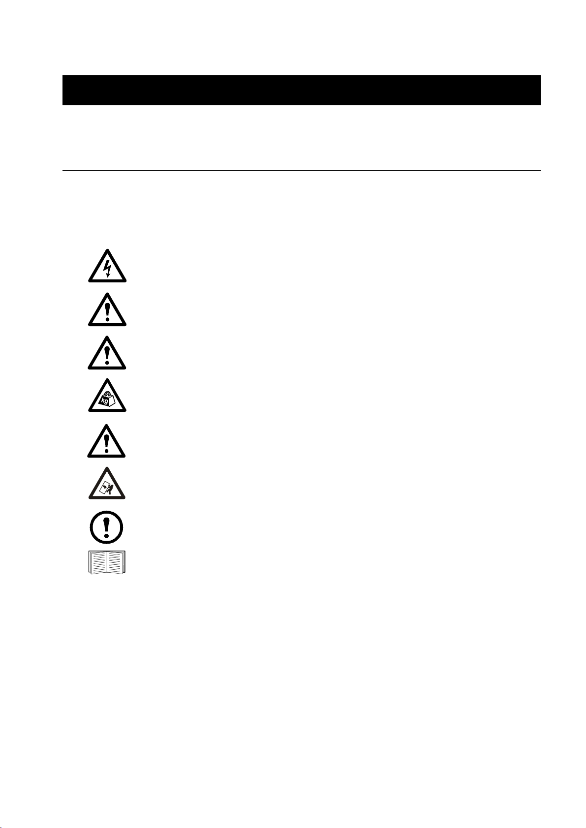
Total Powe r Of f
Set the UPS DC Disconnect circuit breaker and System Enable
switch to OFF.
If applicable, set the XR Battery Enclosure DC Disconnect
circuit breaker to OFF.
Safety: Warnings
px0003a
Set the PDU Main Input circuit breaker
(or switch) to OFF.
Open (turn OFF) the Q1, Q2, and Q3 circuit breakers on the
PDU.
Set the upstream input utility circuit breaker to the OFF or
Locked Out position.
InfraStruXure System - Installation and Start-Up 3
gen0137a
Page 8

Safety: Warnings
DANGER—Risk of Electric Shock!
Electrical Hazard: Hazardous, live parts inside the Symmetra PX UPS are energized from
the battery supply even when the AC power is disconnected.
Hazardous, live parts may exist inside the InfraStruXure PDU because of the Symmetra PX
UPS inverter even when the AC power is disconnected. Test any electrical parts before
touching them.
Emergency Power Off (EPO)
Hazardous voltage from the branch circuit must be isolated from the 24VAC, 24VDC, and contact
closure. 24VAC and 24VDC are considered Class 2 circuits as defined in Article 725 of the National
Electrical Code (NFPA 70) and Section 16 of the Canadian Electrical Code (C22.1).
A Class 2 circuit is a source having limited voltage and energy capacity as follows:
a. If an Inherently Limited Power Source, voltage and energy are limited to less than 30VAC, less
than 30VDC, and 8A.
b. If not an Inherently Limited Power Source, voltage and energy are limited to less than 30VAC,
less than 60VDC, 250 VA, and the current is limited to 1000/V max. The fuse is limited to 5A if
less than 20 VAC or 20 VDC, or 100 /V maximum if less than 30 VAC or 60 VDC.
If you choose to use a 24VAC, 24VDC, or contact closure connection to the EPO, use one of the
following UL-listed wire types:
• CL2 Class 2 cable for general purpose use
• CL2P Plenum cable for use in ducts, plenums, and other space used for environmental air
• CL2R Riser cable for use in a vertical run shaft from floor to floor
• CL2X Limited Use cable for use in dwellings and for use in a raceway
• For installation in Canada, the cable should be CSA Certified, type ELC (extra-low-voltage control
cable).
If you do not use a CL2 cable, route the EPO wiring in conduit that does not contain any branch circuit
wiring.
EMI
This equipment has been tested and found to comply with the limits for a Class A digital device, pursuant
to part 15 of the FCC Rules. These limits are designed to provide reasonable protection against harmful
interference when the equipment is operated in a commercial environment. This equipment generates,
uses, and can radiate radio frequency energy and, if not installed and used in accordance with this user
manual, may cause harmful interference to radio communications. Operation of this equipment in a
residential area is likely to cause harmful interference. The user will bear sole responsibility for
correcting such interference.
This Class A digital apparatus complies with Canadian ICES-003.
Cet appareil numerique de le class A est conforme a la norme NMB-003 du Canada.
4 InfraStruXure System - Installation and Start-Up
Page 9
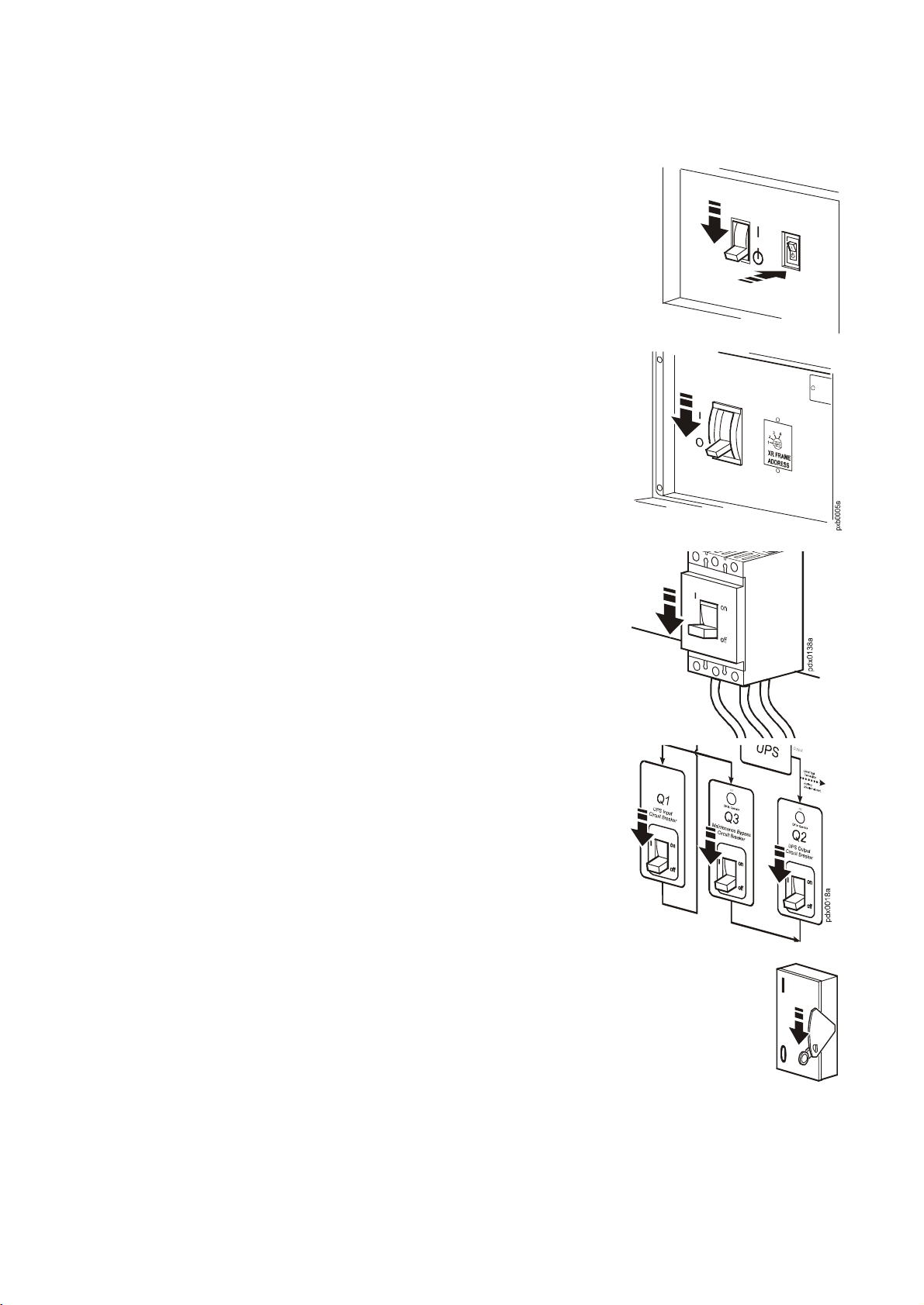
Site Planning
Space Considerations
Use the figure below to determine the space requirements for installing the InfraStruXure PDU,
Symmetra PX UPS, and XR Battery Enclosure. Consult local codes and the NEC for additional
requirements.
Ceiling Clearance
>304 mm/12 in
Minimum Front Clearance
Minimum Rear Clearance
208 V:914 mm/36 in
480 V:1067 mm/42 in
208 V 914 mm/36 in
480 V:1067 mm/42 in
InfraStruXure System - Installation and Start-Up 5
Page 10

Page 11
Installation Procedures
Installation Procedure Overview
This section provides the basic steps to install the InfraStruXure power and rack components. Follow the
references provided with each step for detailed instructions.
Warning: Do not begin installing your InfraStruXure system without an APC Field
Service Engineer present.
Note: Search all boxes and packaging to make sure that they are empty before discarding.
1. Determine the correct placement of the system components by studying the InfraStruXure
Configure-To-Order (CTO) report. Move the Symmetra PX UPS, InfraStruXure PDU, XR Battery
Enclosure, and NetShelter VX Enclosures to their final location.
Warning: If installing InfraStruXure on a raised floor, make sure that the raised-floor
structure has a in
installation. See “Specifications” on page 41.
2. Level the PDU, UPS, NetShelter, and XR Battery Enclosures, using the 13/14-mm wrench included
with each unit.
See “Level the PDU, UPS, NetShelter, and XR Battery Enclosures” on page 10 for detailed
instructions.
3. Exchange side panels and run battery communication cables, if applicable.
See “Exchange Side Panels” on page 11 for detailed instructions.
4. Join adjacent enclosures.
For instructions on joining the PDU, UPS, and XR Battery Enclosure see “Join the PDU, UPS,
and XR Battery Enclosures” on page 13.
For instructions on joining adjacent NetShelter VX Enclosures, see the installation manual
included with your enclosures.
2
/lb rating that will support the full weight of the InfraStruXure
5. Ensure total power off.
See “Total Power Off” on page 3 for detailed instructions.
InfraStruXure System - Installation and Start-Up 7
Page 12

Installation Procedures: Installation Procedure Overview
6. Connect utility conductors to the PDU.
For instructions, see “Connect Utility Conductors to the PDU” on page 14.
7. Connect AC power and control wiring.
See “Connect AC Power and Control Wiring” on page 18 for detailed instructions.
8. Connect DC power wiring, if applicable.
See “Connect DC Power Wiring, if Applicable” on page 20 for detailed instructions.
9 . Connect an EPO switch to the PDU user connection plate
See “Connect an Emergency Power Off Switch” on page 22 for detailed instructions.
10. Connect User Contact Inputs and Relay Outputs to the PDU user connection plate.
See “Connect User Input Contacts and Relay Outputs to the User Connection Plate” on
page 24 for detailed instructions.
11. Install Shielding Troughs, Shielding Partitions, and Cable Ladders.
For instructions, see the manuals included with your Shielding Troughs, Shielding Partitions,
and Cable Ladders.
12. Install the Rack Automatic Transfer Switches (ATS), Rack Power Distribution Units, and other
InfraStruXure rack-mount devices.
For instructions, see the manuals included with your Rack ATS, Rack PDU, or other
InfraStruXure rack-mount device.
13. Route and attach power cables to each Rack ATS and/or Rack PDU.
See “Route and Attach Power Cables to the Racks” on page 25 for detailed instructions.
14. Route and attach communication cables to the InfraStruXure Manager hub (or switch).
See “Route Data Cables to the InfraStruXure Manager Hub (or Switch)” on page 28 for
detailed instructions.
15. Start the system.
Only qualified, APC-trained personnel may perform a system start-up.
See “Start-Up Procedure” on page 29 for detailed instructions.
8 InfraStruXure System - Installation and Start-Up
Page 13

Installation Procedures: Installation Procedure Overview
16. Configure the InfraStruXure Manager.
For instructions, see the manual included with your InfraStruXure Manager.
Tools Required
The following tools are required to perform the procedures in this manual. Additional tools may be
required for components not covered in this manual.
Tool Supplied?
13-mm socket wrench No
17-mm socket wrench No
T-20 screwdriver No
Standard screwdriver No
Level No
Open-ended wrench (14 mm) for adjusting the leveling feet Yes
Step ladder No
Crimper No
Vo l t - m e t e r N o
Phase-rotation meter No
InfraStruXure System - Installation and Start-Up 9
Page 14
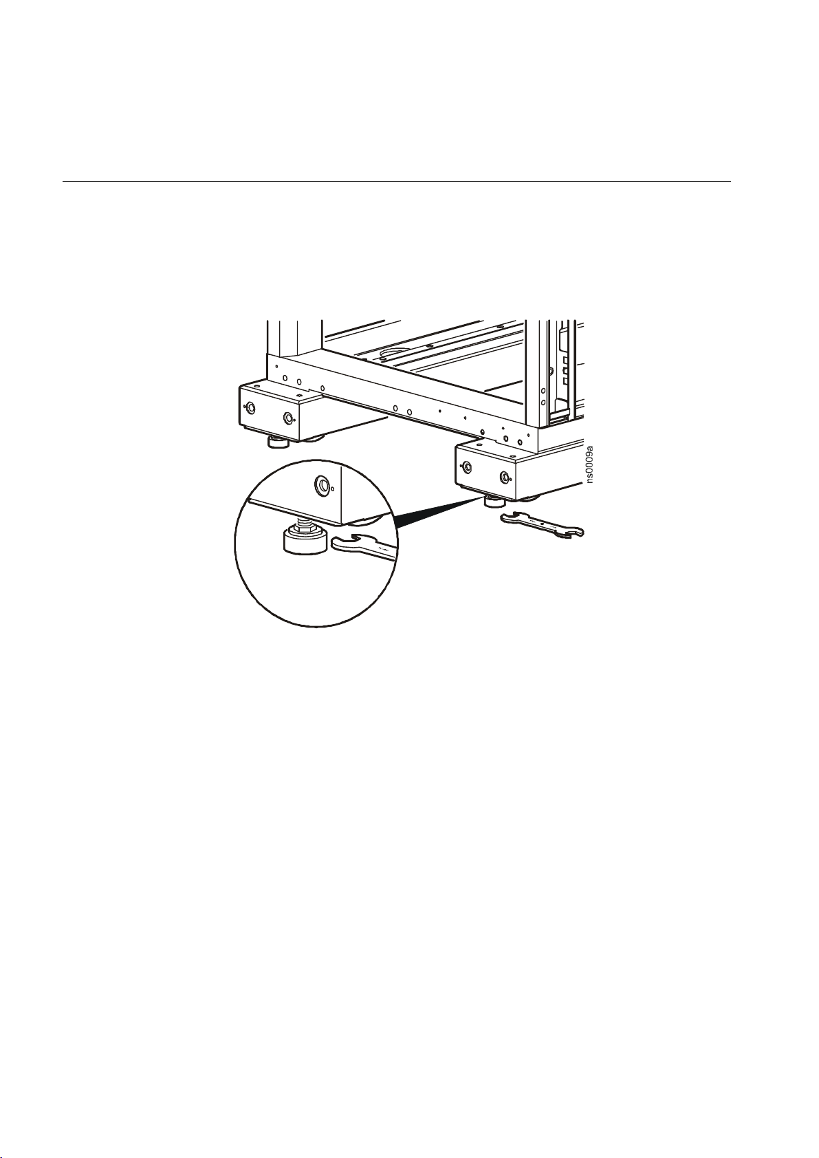
Level the PDU, UPS, NetShelter, and XR Battery Enclosures
Leveling feet are attached under the enclosure at each corner. The leveling feet can help provide a stable
base if the selected floor space is uneven, but they are not intended to compensate for a badly sloped
surface. To level the enclosure:
1. Use a 14-mm end of the open-ended wrench (provided) to extend the leveling foot until it makes
firm contact with the floor.
2. Repeat step 1 for each of the remaining leveling feet.
3. Use a level to determine which feet need further adjustment to level the enclosure. Adjust as
necessary.
10 InfraStruXure System - Installation and Start-Up
Page 15
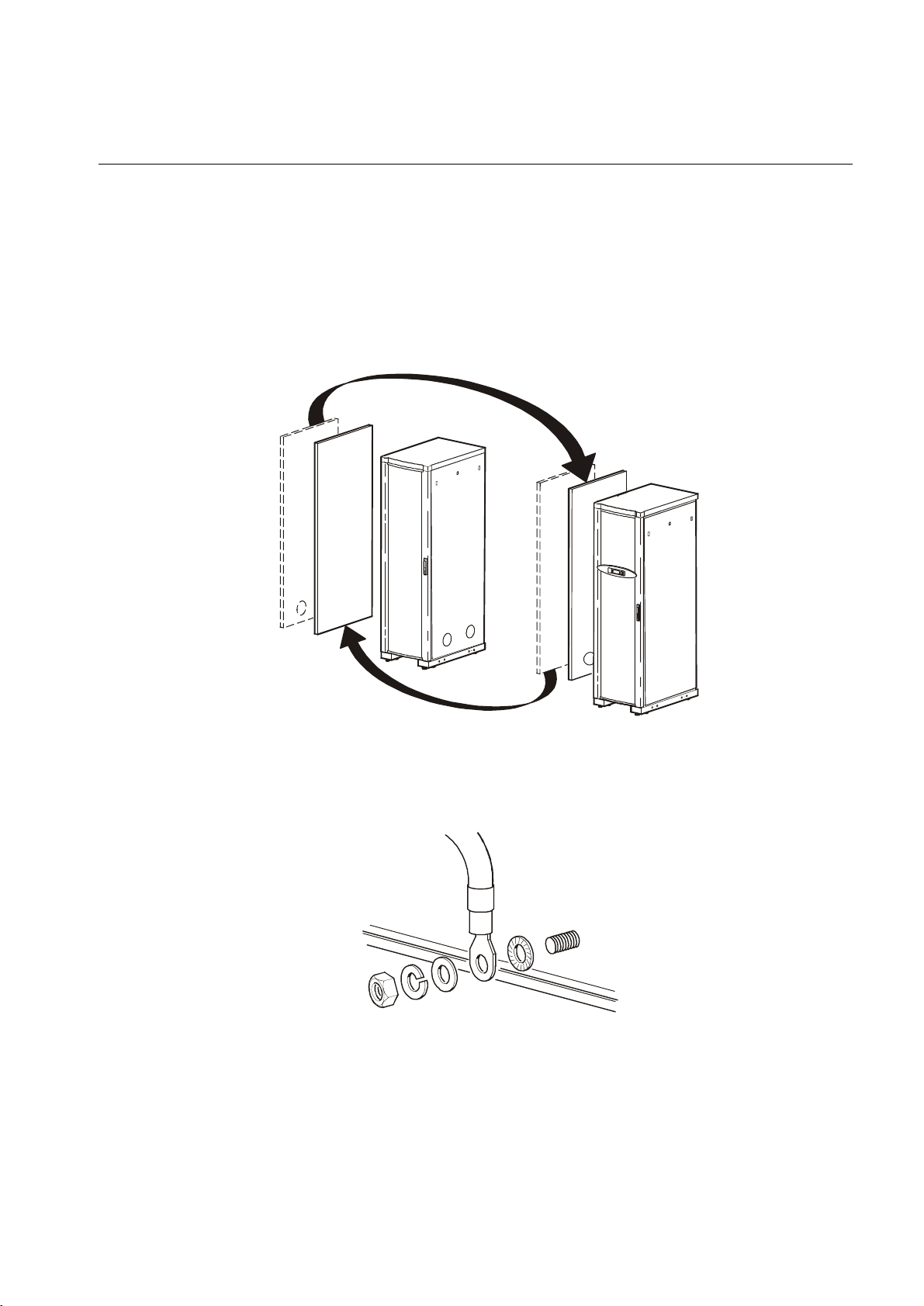
Exchange Side Panels
Before installing the InfraStruXure PDU, Symmetra PX UPS, and XR Battery Enclosure, exchange side
panels so that the adjacent panels will have matching holes for joining the enclosures together and for
routing input and output wiring between them. The following side panels will need to be exchanged:
• Adjacent side panels of a PDU and UPS
• Adjacent side panels of a XR Battery Enclosure and a UPS
• Adjacent side panels of two XR Battery Enclosures
Exchange Side Panels
1. Detach the ground wires from the side panels.
2. Remove the solid side panels from the side of the UPS that will be adjacent to the PDU and the XR
Battery Enclosure in the planned configuration.
psx013 6a
gen0 303a
InfraStruXure System - Installation and Start-Up 11
Page 16

Installation Procedures: Exchange Side Panels
3. Remove the side panels from the sides of the PDU and XR Battery Enclosure that will not be
adjacent to the UPS.
4. Remove the rear hole covers from the panels that you removed in step 3.
Connect Battery Enclosure communication cables
psx002 0a
1. Route the communication cable through the hole between the UPS and the XR Battery Enclosure.
Route the cable from the side of the UPS to which it is attached, around the back of the UPS, and
through the hole on the other side of the UPS to the front of the XR Battery Enclosure.
2. Connect the cable to Port 1 on the first adjacent XR
Battery Enclosure’s XR Communication Card.
3. Connect Port 2 on the first XR Battery Enclosure to
Port 1 on the next XR Battery Enclosure. Route the
cable the same way as described in step 5. Continue
until all XR Communication Cards are connected.
4. Locate the XR Communication Card terminator and
insert it into the open port of the last XR Battery
Enclosure in your configuration.
XR Battery Enclosure 1
Symmetra PX UPS
XR Communications Card
XR Battery Enclosure 2
XR Communications Card
XR Communications Card
Port 2
Port 1
Ter m i n a t o r
Term i na t o r
Port 2
Port 1
e
l
b
a
C
.
m
m
o
C
Port 2
Port 1
e
l
b
a
C
.
m
m
o
C
psx0145a
5. Install, on the UPS, the side panels that you removed from the PDU and the XR Battery Enclosure
in step 3 and re-attach the ground wires.
6. Install, on the PDU and the XR Battery Enclosure, the solid side panel that you removed from the
UPS in step 2 and re-attach the ground wires.
12 InfraStruXure System - Installation and Start-Up
Page 17

Join the PDU, UPS, and XR Battery Enclosures
1. Move the PDU, Symmetra PX UPS, and XR Battery Enclosures into position, aligning the holes in
the adjacent side panels.
2. Level the PDU, Symmetra PX UPS, and XR Battery Enclosure by using a level and adjusting the
leveling feet on each enclosure.
3. The following enclosures will need to be attached, refer to the graphic below:
• An adjacent PDU and UPS
• An adjacent XR Battery Enclosure and UPS
• Adjacent XR Battery Enclosures
psx0023a
InfraStruXure System - Installation and Start-Up 13
Page 18

Connect Utility Conductors to the PDU
Electrical Hazard: A licensed electrician must connect input conductors to the PDU!
Access the PDU Main Input switch
1. Open the back doors of the PDU, unlock the top, smaller door, using the provided red key.
2. Loosen the two screws holding the larger, hinged door in place.
Attach conduit to the PDU for the input conductors
1. Remove the rectangular gland plate by loosening the captive screws, using a Phillips or standard
screwdriver:
For wiring under a raised floor: Remove the plate in the floor of the PDU.
14 InfraStruXure System - Installation and Start-Up
Page 19

Installation Procedures: Connect Utility Conductors to the PDU
For overhead wiring: Remove the user connection plate from the top of the PDU.
2. Cut an appropriately-sized hole in the gland plate for the conduit.
3. Re-attach the gland plate.
4. Install a lock-nut and bushing to the conduit.
5. Thread the conduit through the hole.
Install a circuit breaker
Warning: When you connect the InfraStruXure PDU to utility, you must install a circuit
breaker to protect the PDU against over-current.
Determine the amperage of the circuit breaker that you need to install:
Input Voltage Circuit Breaker Amperage
208V 175A
480V 80A
600V 60A
InfraStruXure System - Installation and Start-Up 15
Page 20

Installation Procedures: Connect Utility Conductors to the PDU
Route the input conductors to the Main Input switch
For overhead wiring, run the input conductors directly to the Main Input switch.
For wiring under a raised floor, run the input conductors through the
wireway (
) within the PDU to the Main Input switch.
Connect input conductors
Electrical Hazard: A licensed electrician must connect input conductors to the PDU!
Torque specs and tools required. Before connecting to the terminals, verify the torque specs below
by checking the specifications on the Main Input switch.
Terminal Torque Tools
L1, L2, L3 150 in-lb 6-mm Allen wrench
†
N
G, GEC 4–6 AWG: 45 in-lb
†
Only on PDUs without a transformer.
125 in-lb 13-mm socket wrench
Slotted screwdriver
8 AWG: 40 in-lb
16 InfraStruXure System - Installation and Start-Up
Page 21

Installation Procedures: Connect Utility Conductors to the PDU
At the Main Input switch, connect the input wiring according to the labels on the switch and the
illustrations below.
Warning: Connect the conductors to the terminals according to the labels on the
terminals. Use copper conductors only.
208/480/600 V input with a transformer:
L2
3-phase, 3-wire + ground + GEC to a
suitable grounding electrode
G
L1
GEC
L3
208 V input without a transformer:
208 V, 3-phase, 4-wire + ground
G
L2
L1
L3
InfraStruXure System - Installation and Start-Up 17
Page 22

Connect AC Power and Control Wiring
Electrical Hazard: Only Field Service Engineers or qualified personnel trained by APC
may connect the AC power and control wiring.
Connect AC power and control wiring to the UPS. There are five input wires and four output wires coiled
on the floor of the PDU. Each set of wires is labeled. The control wires for the UPS Maintenance Bypass
control board and the UPS EPO control board are also coiled in the PDU.
To make the connections, remove the rear lower panel of the UPS and the rear panel of the PDU. Use the
opening in the side panels of the enclosures to run the wires.
Connect AC power wiring.
Attach the input ground wire to the ground lug marked to the right of the input terminals.
Attach the input wires (L1, L2, L3, N) to the UPS input terminals with corresponding labels.
Attach the output wires (L1, L2, L3, N) to the UPS output terminals with corresponding labels.
Attach the output wires (L1, L2, L3, N) to the four UPS output terminals wit h corresponding labels.
PDU
18 InfraStruXure System - Installation and Start-Up
psx0032b
UPS
Page 23

Installation Procedures: Connect AC Power and Control Wiring
Connect control wiring.
1. Connect the EPO control wires from the PDU and the XR Battery Enclosure (if applicable) to the
EPO board on the UPS. The control wires are harnessed and coiled in the floor of the PDU and the
XR Battery Enclosure. The PDU harness connects to J6 and the XR Battery Enclosure harness
connects to J8.
2. Connect the Maintenance Bypass control wire harness from the PDU to the Maintenance Bypass
interface board of the UPS. There are two wire harnesses coiled and secured in the PDU. One is a 6wire harness and the other is a 4-wire harness.
Note: A jumper wire must be installed in position 13 and 14.
InfraStruXure System - Installation and Start-Up 19
Page 24

Connect DC Power Wiring, if Applicable
X
X
Electrical Hazard: Only Field Service Engineers or qualified personnel trained by APC
may connect the XR Battery Enclosure to the Symmetra PX UPS or to another XR Battery
Enclosure.
Warning: The supplied power and ground wires are for internal side-panel wiring only.
These wires are not for use in external conduits.
Electrical Hazard:
Before you begin connecting the DC power wiring, ensure that there are
no battery units installed in the XR Battery Enclosures. Do not install battery units until
instructed to do so.
Cascade XR Battery Enclosures
If you have multiple XR Battery Enclosures as part of your InfraStruXure system, you can cascade XR
Battery Enclosures to a Symmetra PX UPS. Starting with the XR Battery Enclosure furthest away from
the UPS:
1. Route DC output cables and the ground cable (coiled on the floor of the enclosure) from one XR
Battery Enclosure to the next XR Battery Enclosure through the adjacent holes in the side panels of
the enclosures.
2. Connect the DC output cables from one XR Battery Enclosure to the DC Input Circuit Breaker of
the next XR Battery Enclosure [(+) to (+), (CT) to (CT), (–) to (–)].
3. Connect the ground wire from one XR Battery Enclosure to the grounding stud on the next XR
Battery Enclosure.
XR (GND)
To
XR Battery
Enclosure
XR Battery Enclosure
20 InfraStruXure System - Installation and Start-Up
XR (–)
R (CT)
XR (+)
R Battery Enclosure
pxb0007a
To
UPS
Page 25

Installation Procedures: Connect DC Power Wiring, if Applicable
Connect power cables from the XR Battery Enclosure to the Symmetra PX UPS
1. Route the XR Battery Enclosure DC output cables to the Symmetra PX UPS through the hole in the
adjacent side panels.
2. Connect the XR Battery Enclosure DC output cables to the Symmetra PX UPS DC input terminal
[(+) to (+), (CT) to (CT), (–) to (–)].
Tighten the lugs on the terminals only to the torque specified: the power terminal lug
diameter is 8 mm with a torque value of 53 lb/in (6Nm).
3. Connect the XR Battery Enclosure ground cable to the Symmetra PX UPS ground stud through the
hole in the adjacent side panels.
XR (GND)
XR Battery Enclosure
XR (–)
XR (+)
XR (CT)
pxb0006 a
Symmetra PX UPS
InfraStruXure System - Installation and Start-Up 21
Page 26

Connect an Emergency Power Off Switch
Overview
To provide a mechanism for
emergency power off, attach a
remote switch (not included) to the
EPO interface on the PDU
monitoring unit. The EPO
interface (
PDU Main Input switch (
to the UPS internal EPO switch
(
).
When the EPO is activated, the
main input breaker to the PDU
transformer is opened, the UPS
DC Disconnect breaker is opened,
and the UPS System Enable switch is turned off. In this sequence, there is no power from the PDU
transformer and there is no power from the UPS inverters and batteries.
) is connected to the
) and
Note: Contact closure is recommended.
Connecting the switch. The Emergency
Power Off (EPO) switch connects to the PDU
user connection plate. The figure on the right
shows the location of the user connection plate
on the roof of the PDU. Connect a switch using
one of three following connections:
• Contact closure
•24Vac
•24Vdc
Note: APC offers an optional InfraStruXure EPO System (EPW9). Contact your APC sales
representative, or visit the APC Web site (www.apc.com) for more information.
22 InfraStruXure System - Installation and Start-Up
Page 27

Installation Procedures: Connect an Emergency Power Off Switch
Connect an EPO switch to the user connection plate
1. Connect the switch to the EPO connection point terminals located on the bottom side of the PDU
user connection plate. Read the label next to the terminal block to determine which terminals to
connect to for the signal type you are using:
– Contact Closure—Normally Open
– Contact Closure—Normally Closed
– 24 Vac/Vdc—Normally Open
Normally Open Dry Contacts
External set of
Normally Open Dry Contacts
External set of
Normally Closed Dry Contacts
External set of
24V AC or DC Power Supply
2. Verify that the EPO DIP switches on the PDU monitoring unit are configured properly for the signal
type you are using. The labels above the switches and the figure below show the correct settings for
both the Normally Open (NO) and Normally Closed (NC) position.
Location of switches
on PDU monitoring unit
See the Operation Manual for information on how to test the EPO.
InfraStruXure System - Installation and Start-Up 23
Page 28

Connect User Input Contacts and Relay Outputs to the User Connection Plate
Overview
Make contact closure connections (NO or NC) at
the user connection plate to monitor dry contacts.
You can make up to four input contacts and four
relay output connections.
The figure at the right shows the location of the
user connection plate on the roof of the PDU
enclosure.
Make the connections from inside the enclosure,
or remove the user connection plate and make the
connections.
Remove the plate using a Phillips or
standard screw driver to loosen the two
captive screws. Use the knockout in the
plate to route cables to and from the user
connections on the plate. If you remove the
plate, make sure that you do not disturb the
existing connections.
See the Operation Manual for
information on how to configure the input contacts and relay outputs.
24 InfraStruXure System - Installation and Start-Up
Page 29

Route and Attach Power Cables to the Racks
Overhead Wiring
Route and attach power cables to equipment racks. If you ordered overhead wiring, connect the
prewired power cables of the InfraStruXure PDU as follows:
1. Install the Shielding Troughs, Shielding Partitions, and Cable Ladders so that you can route power
cables from the PDU to the Netshelter Enclosures.
2. Find the numbers that indicate the enclosure to which each power cable will supply power. These
numbers appear on the roof of the PDU where the power cables exit, and on the ends of each power
cable.
Note: The enclosures are not numbered. Consult your APC InfraStruXure Configure-To-Order
(CTO) report to determine the enclosure associated with each power cable.
3. Beginning with the power cables for the enclosures farthest from the PDU, run each power cable
within the Shielding Trough along the row and, if necessary, across one or more Cable Ladders to
the enclosure to which it will provide power.
Note: Ensure that the L21-20 twist-lock connector at the end of each power cable always lies
on top of any longer power cables in the Shielding Trough.
4. Connect the appropriate power cable to APC power management equipment in the enclosure in one
of the four following ways:
– For single-feed devices without redundancy: attach a power
cable directly to a Rack PDU installed in a NetShelter VX
Enclosure.
psx0054a
– For dual-feed devices within a
redundant system: attach a power cable
from each PDU into two different Rack
PDUs in the NetShelter VX Enclosure.
InfraStruXure System - Installation and Start-Up 25
Page 30

Installation Procedures: Route and Attach Power Cables to the Racks
– For single-feed devices within a
redundant system with an Automatic
Transfer Switch: connect a power cable
to the Automatic Transfer Switch (A
and B feeds) and connect the Automatic
Transfer Switch power cord to a Rack
PDU in the NetShelter VX Enclosure.
– For dual-feed devices in a redundant
system with an Automatic Transfer
Switch: connect a power cable from
each PDU to the Automatic Transfer
Switch’s A and B feeds, and another
power cable from one PDU to a Rack
PDU, and the Automatic Transfer
Switch’s power cord to a second Rack
PDU in the NetShelter VX Enclosure.
Note: Lay the cables neatly in the Shielding Trough to minimize cable buildup.
5. From each NetShelter VX Enclosure, run the power cable of the appropriate APC power
management device out the roof of the enclosure, through the notch in the rear side of the Shielding
Trough, to the connector of the appropriate power cable from the PDU. Plug the two connectors
together, and twist them clockwise to lock.
Under Floor Wiring
Electrical Hazard: A licensed electrician must route and connect the power cables for
under-floor wiring.
Warning: Make sure all wire connections and circuit breaker connections are properly
torqued.
To wire each power cable to an enclosure:
1. Push out a knock-out filler in the floor of the PDU to create an opening for the cable.
2. Install Liquidtite™ waterproof conduit under the floor from each enclosure to the PDU.
3. From the Rack PDU or Rack ATS in each enclosure, thread the appropriate power cable (for your
26 InfraStruXure System - Installation and Start-Up
Page 31

Installation Procedures: Route and Attach Power Cables to the Racks
application) from the enclosure through the Liquidtite conduit to the PDU.
4. At the PDU, route the cable through the opening you created in step 1
and then up through the wireway (
) at either side of the PDU. This
will allow you to connect the cable to the circuit breaker panel.
5. At the circuit breaker panel, cut the wires to the proper length, and
connect the power cable’s individual wires:
a. If you have branch current monitoring installed, route each phase
conductor through a current sensor. If it is a three-phase cable, route
the L1, L2, and L3 wires through a separate current sensor.
b. Connect the L1, L2, and L3 wires to the circuit breaker(s). The
illustration below shows a three-phase cable connecting to three
single pole breakers; however, you can also connect a three-phase
cable to a three-pole breaker, or a single-phase cable to a single-pole
circuit breaker.
c. Connect the neutral wire to the closest open termination point on the
Neutral Bar (N).
d. Connect the ground wire to the closest open termination point on the Ground Bar (G).
Caution: Any multi-circuit power cable that is installed by an electrical contractor must
be installed with a 3-pole circuit breaker.
InfraStruXure System - Installation and Start-Up 27
Page 32

Route Data Cables to the InfraStruXure Manager Hub (or Switch)
1. Connect a CAT-5 network cable (provided) to the network or 10BaseT ports on your APC
InfraStruXure devices. The following devices need to be connected:
Automatic Transfer Switch
Environmental Monitoring Unit
Rack PDU
Symmetra PX UPS
InfraStruXure PDU
2. Run the connected CAT-5 network cables through the data cable troughs to the InfraStruXure
Manager Hub (or Switch).
3. Connect each device’s network cable to any available station port in the InfraStruXure Manager
Hub (or Switch). Station ports are those with an x after the number (e.g. 2x).
28 InfraStruXure System - Installation and Start-Up
Page 33

Start-Up Procedure
Apply power to the system
Safety warnings
This section provides instructions on how to perform a system start-up. Do not skip any steps in this
procedure.
Electrical Hazard:
personnel may perform a system start-up. Ensure that all power is off. See “Total Power
Off” on page 3.
Warning: Do not install any batteries into the XR Battery Enclosure or power modules
into the Symmetra PX UPS until instructed to do so.
1. Set the upstream main utility input circuit breaker to ON.
2. Ensure A-B-C clockwise phase rotation at the top of the Main Input switch on the
PDU, using a phase rotation meter.
3. Set the Main Input switch on the PDU to ON.
4. Verify A-B-C clockwise phase rotation at the top of the primary
winding of the transformer, using a phase rotation meter.
5. Verify that the proper voltage is present on the secondary
winding of the transformer
(208 V, metered phase-to-phase), using a true RMS voltmeter.
Only APC Field Service Engineers or qualified, APC-trained
gen0168a
InfraStruXure System - Installation and Start-Up 29
Page 34

6. Install at least one battery module (four
battery units) in the Symmetra PX UPS.
Install battery modules, starting in the lowest
available shelf. Position the battery unit
between the grooves, and slide it completely
into the enclosure.
Heavy: Use two people to lift and install battery units.
Electrical Hazard:
The DC bus in the Symmetra PX UPS is energized when battery
modules are installed, even when the DC Disconnect circuit breaker is open.
7. Install at least one power module in the
Symmetra PX UPS. Install power modules
starting from the lowest available shelf.
Push each module completely into the
enclosure.
Heavy: Use two people to lift and install power modules.
px001 2a
30 InfraStruXure System - Installation and Start-Up
Page 35

8. Secure the power module:
a. Tighten the screws on each side of
the power module.
b. Turn the locking latch clockwise
until the arrow on the knob faces the
power module.
Note: The power module will not start unless the locking latch is engaged.
Start-Up Procedure: Apply power to the system
px0019a
9. Set the UPS DC Disconnect circuit breaker to ON, and then set the
UPS System Enable switch to ON.
10. If applicable, set the XR Battery Enclosure DC Disconnect
circuit breaker to ON.
When the System Enable switch is in the ON position, the UPS
is running on battery. The Startup screen appears on the display
interface of the Symmetra PX UPS.
px0013a
PowerView RM
Rev: 000 English
Please wait...
Then, the top-level status screen appears on the display interface.
This may take up to 40 seconds.
InfraStruXure System - Installation and Start-Up 31
Fuel %
Load %
In 000V out000V 60Hz
Runtime:
||||||||||||
|||
1hr 2m
Page 36

Start-Up Procedure: Apply power to the system
Verify UPS battery operation
1. Read the messages displayed on the
Symmetra PX UPS display interface. Note
any alarms and verify that they are
appropriate for start-up conditions.
2. Command the UPS to apply power to the
load:
a. Press the
ESC key to open the top-level
menu.
b. Select Control, and press the
ENTER key.
c. Select Tu rn L oa d O n from the Control
menu, and press the
ENTER key.
d. On the next screen: select Yes, UPS Load
ON, and press the
ENTER key.
Top-Level Status Screen
Fuel %
Load %
In 208V out000V 60Hz
Runtime:
||||||||||||
|||
1hr 2m
Top- Le v el Me nu
Control
Status
Setup
Accessories
Logging
Display
Diags
Help
Control Menu
UPS Into Bypass
Do Self Test
Simulate Power Fail
Graceful Reboot
Graceful Turn Off
Start Runtime Cal
Turn Load On
Confirmation Screen
Confirm
Yes, UPS Load ON
No, Abort
The interface will display the following
screen:
UPS has been
commanded to turn
load power on...
The interface will display the following fault
message:
e. Select Start Now, and press the
ENTER key.
Low/No AC input
Start up on Batt?
Start Now
Abort Start-up
The interface will display the following
screen:
UPS has been
commanded to turn
load power on...
The LOAD ON LED illuminates and the
interface displays the following screen:
UPS load is on
Press any key...
After you have verified that the UPS operates correctly in battery operation, shut down the UPS:
32 InfraStruXure System - Installation and Start-Up
Page 37

Start-Up Procedure: Apply power to the system
3. Command the UPS to turn off power to the
load:
a. Press the
ESC key at the top-level status
screen to open the top-level menu and have
access to eight submenus.
b. Select Control, and press the
ENTER key.
c. Select Tu rn L oa d O f f from the Control
menu, and press the
ENTER key.
d. On the next screen: select Yes, UPS Load
OFF, and press the
ENTER key.
The LOAD ON LED turns off and the
interface displays the following two screens:
Top-Level Menu
Control
Status
Setup
Accessories
Logging
Display
Diags
Help
Control Menu
UPS Into Bypass
Do Self Test
Simulate Power Fail
Graceful Reboot
Graceful Turn Off
Start Runtime Cal
Turn Load Off
Confirmation Screen
Confirm
Yes, UPS Load OFF
No, Abort
UPS has been
commanded to turn
load power off...
4. Set the UPS System Enable switch to OFF,
and then set the UPS DC Disconnect circuit
breaker and to OFF.
5. If applicable, set the XR Battery Enclosure
DC Disconnect circuit breaker to OFF.
UPS load is off
Press any key...
px0003a
InfraStruXure System - Installation and Start-Up 33
Page 38

Start-Up Procedure: Apply power to the system
Verify proper voltage and phase rotation at the UPS
1. Close (turn ON) the Q1 circuit breaker on the PDU to apply power to the UPS.
2. Ensure A-B-C clockwise rotation at the UPS input terminal block, using a phase rotation meter.
3. Verify proper voltage is present at the UPS input terminal block (208V, metered phase-to-phase),
using a true RMS voltmeter.
Start the UPS
1. Set the UPS DC Disconnect circuit breaker to ON, and then set the
UPS System Enable switch to ON.
2. If applicable, set the XR Battery Enclosure DC Disconnect
circuit breaker to ON.
When the System Enable switch is in the ON position, the
Startup screen appears on the display interface of the Symmetra
PX UPS.
px0013a
PowerView RM
Rev: 000 English
Please wait...
Then, the top-level status screen appears on the display interface.
This may take up to 40 seconds.
34 InfraStruXure System - Installation and Start-Up
Fuel %
Load %
In 208V out000V 60Hz
Runtime:
||||||||||||
|||
1hr 2m
Page 39

Start-Up Procedure: Apply power to the system
3. Read the messages displayed on the
Symmetra PX UPS display interface. Note
any alarms and verify that they are
appropriate for start-up conditions.
4. Command the UPS to apply power to the
load:
a. Press the
ESC key to open the top-level
menu.
b. Select Control, and press the
ENTER key.
c. Select Tu rn L oa d O n from the Control
menu, and press the
ENTER key.
d. On the next screen: select Yes, UPS Load
ON, and press the
ENTER key.
Top-Level Status Screen
Fuel %
Load %
In 208V out000V 60Hz
Runtime:
||||||||||||
|||
1hr 2m
Top- Le v el Me nu
Control
Status
Setup
Accessories
Logging
Display
Diags
Help
Control Menu
UPS Into Bypass
Do Self Test
Simulate Power Fail
Graceful Reboot
Graceful Turn Off
Start Runtime Cal
Turn Load On
Confirmation Screen
Confirm
Yes, UPS Load ON
No, Abort
The interface will display the following
screen:
The LOAD ON LED illuminates and the
interface displays the following screen:
5. Close (turn ON) the Q2 circuit breaker on the PDU.
UPS has been
commanded to turn
load power on...
UPS load is on
Press any key...
InfraStruXure System - Installation and Start-Up 35
Page 40

Start-Up Procedure: Apply power to the system
Verify bypass operation
1. Command the UPS into static bypass operation
through the UPS display interface:
a. Press the
ESC key to open the top-level
menu.
b. Select Control on the top-level menu, and
press the
ENTER key.
c. Select UPS Into Bypass on the Control
menu, and press the
ENTER key.
d. On the next screen: select Yes , U P S i n to
Bypass, and press the
ENTER key.
The BYPASS LED illuminates and the
following screens appear:
Top-Level Menu
Control
Status
Setup
Accessories
Logging
Display
Diags
Help
Control Menu
UPS Into Bypass
Do Self Test
Simulate Power Fail
Graceful Reboot
Graceful Turn Off
Start Runtime Cal
Turn Load On
Confirmation Screen
Confirm
Yes, UPS into Bypass
No, Abort
UPS has been
commanded to go
into Bypass...
UPS load is in Bypass
Press any key...
Note: The H3 LED above the Q3 circuit breaker illuminates, but do not operate the circuit
breaker.
2. Use a true RMS voltmeter to make sure that there is no difference in potential between L1 IN and
L1 OUT, L2 IN and L2 OUT, and L3 IN and L3 OUT on the Q3 circuit breaker. The Q3 circuit
breaker must be in the OFF position. The top side of Q3 will be utility voltage and the bottom side
of Q3 will be the voltage from the UPS in static bypass. Voltage should be less than 2 volts.
Note: Q3 is a 4-pole circuit breaker. Be sure to measure L1 to L1, L2 to L2, and L3 to L3.
36 InfraStruXure System - Installation and Start-Up
Page 41

Start-Up Procedure: Apply power to the system
3. Close (turn ON) the Q3 circuit breaker on the InfraStruXure
PDU.
Note: The H2 LED above the Q2 circuit breaker illuminates, indicating that it is safe to operate
the Q2 circuit breaker.
4. Open (turn OFF) the Q2 circuit breaker on the InfraStruXure
PDU.
The UPS will display a Forced Bypass message on the
display interface and the Fault LED will be red.
5. Command the UPS into static bypass operation
through the UPS display interface:
a. Press the
ESC key to open the top-level
menu.
b. Select Control on the top-level menu, and
press the
ENTER key.
c. Select UPS Into Bypass on the Control
menu, and press the
ENTER key.
d. On the next screen: select Yes , U P S i n to
Bypass, and press the
ENTER key.
Top-Level Menu
Control
Status
Setup
Accessories
Logging
Display
Diags
Help
Control Menu
UPS Into Bypass
Do Self Test
Simulate Power Fail
Graceful Reboot
Graceful Turn Off
Start Runtime Cal
Turn Load On
Confirmation Screen
Confirm
Yes, UPS into Bypass
No, Abort
Note: The H2 LED above the Q2 circuit breaker illuminates, indicating that it is safe to operate
the Q2 circuit breaker.
InfraStruXure System - Installation and Start-Up 37
Page 42

Start-Up Procedure: Apply power to the system
6. Close (turn ON) the Q2 circuit breaker on the InfraStruXure
PDU.
Note: The H3 LED above the Q3 circuit breaker illuminates, indicating that it is safe to operate
the Q3 circuit breaker.
7. Open (turn OFF) the Q3 circuit breaker on the InfraStruXure
PDU.
8. Command the UPS out of static bypass operation through the
UPS display interface:
E
SC
a. Press the
key at the top-level status screen to open the
top-level menu and have access to eight submenus.
b. Select Control, and press the
c. Select UPS Out of Bypass on the Control menu, and press
the
E
NTER
key.
E
NTER
key.
On the next screen: select Yes, UPS out of Bypass, and press
the
E
NTER
key.
Power the PDU Distribution Breakers
1. Ensure that the Q2 circuit breaker on the PDU is closed (ON).
Note: When Q2 is closed, the PDU distribution panel is energized.
38 InfraStruXure System - Installation and Start-Up
Page 43

Start-Up Procedure: Apply power to the system
2. Close (turn ON) the PDU distribution
panel breakers.
Note: When the distribution panel circuit breakers are closed, the PDU power cables and
connected equipment are energized.
Configure the InfraStruXure Manager
Once all equipment is installed, the network cables are connected to the InfraStruXure Manager hub (or
switch), and start-up of the system is complete, configure the InfraStruXure Manager.
For instructions, see the InfraStruXure Manager Installation and Quick-Start manual included
with your InfraStruXure Manager.
Note: If you use PowerChute Network Shutdown (PCNS) software with your InfraStruXure
UPS, your UPS must have a connection to the “User LAN” (public network) for PCNS to
function correctly. If the Network Management Card installed in your UPS is connected to the
InfraStruXure Manager’s “APC LAN,” you must install a second Network Management Card
in your UPS and connect it to the “User LAN”
(public network) to use PCNS.
InfraStruXure System - Installation and Start-Up 39
Page 44

Page 45

Specifications
40 kW InfraStruXure PDU
Electrical PD40F6FK1-M PD40G6FK1-M PD40L6FK1-M
Input
Nominal Voltage Requirements 208/120 V 480/277 V 600/346 V
Nominal Current 125 A 54 A 43 A
Frequency 57–63 Hz 57–63 Hz 57–63 Hz
Voltage Configuration
Transformer 3W + G + GEC
Without Transformer 4W + G
Upstream Circuit Breaker
Main Input Conductor Size
UPS Breaker Size 175 AT 175 AT 175 AT
Maximum Continuous Current 155 A 67 A 54 A
††
‡
175 AT 80 AT 60 AT
3/0 AWG #3 AWG #4 AWG
Grounding PE node (from AC or floor grid)
Output
Voltage AC 3-phase 4-wire PE
Nominal Voltage 208:120 V WYE
UPS Breaker Size 150 AT 150 AT 150 AT
Max. Distribution Breaker Size 150 AT 150 AT 150 AT
Number of Distribution Panels 2 × 225A, 42- position
Full Load Rating 40 kW 40 kW 40 kW
Max. Contin Current + 125% overload 139 A 139 A 139 A
Nominal Current 111 A 111 A 111 A
Internal Static Switch Fuses
Over-current Protection
PDU Current Determined by UPS
Grounding Separately derived neutral/ground bond
Wiring
UPS to PDU 3W + G (1/0 AWG)
†
175 A
PDU to Distribution Panels 4W + G (1/0 AWG)
Distribution Panels to Racks/Power Strips 4W + G (12 AWG)
Power Cable Connections L21-20 connector system
InfraStruXure System - Installation and Start-Up 41
Page 46

Specifications: 40 kW InfraStruXure PDU
Electrical PD40F6FK1-M PD40G6FK1-M PD40L6FK1-M
Power Cable Lengths various
Recommended Wire Sizing
L1, L2, L3, N
G
GEC
‡
3/0 AWG 4 AWG 4AWG
6 AW G 8 AWG 8 AW G
4 AW G 4 AWG 4 AW G
Power Cable—top Accommodates 28, 3-phase power cables (42 knockouts)
Power Cable—bottom Accommodates 28, 3-phase power cables (48 knockouts)
Panel Boards
Panel Style 3-phase
Number of Panels per PDU 2 maximum
Positions per Panel 42
3-Phase Breakers per Panel 14 maximum
1-Phase Breakers per Panel 42 maximum
Panel Rating 240 V/225 A (per phase)
Breaker Pitch 3/4 in
Accessibility Through front of the unit
Relay Outputs
Nominal Switching Capacity 1 A at 30 Vdc
Maximum Switching Power 30 W
Maximum Switching Voltage 60 Vdc
Maximum Switching Current 2 ADC
Maximum Carrying Current 2 ADC
Surge Ratings 2 kV per Bellcore TA-NWT-001089
1.5 kV per FCC part 68
Physical PD40F6FK1-M PD40G6FK1-M PD40L6FK1-M
Dimensions (H×W × D)
PDU 81×24×36 in. (2057 × 610 × 914 mm)
Shipping 86 × 36 × 48 in (2184 × 914 × 1219 mm)
Weight
PDU 1580lb (718.18kg)
Shipping 1680lb (763.6kg)
Heat Output With Transformer 4645BTU 4617 BTU 3425BTU
Transformer (if installed)
Type Isolation Step-down Step-down
42 InfraStruXure System - Installation and Start-Up
Page 47

Specifications: 40 kW InfraStruXure PDU
Physical PD40F6FK1-M PD40G6FK1-M PD40L6FK1-M
Configuration Delta to WYE
Maximum Power Rating 60kVA
Maximum Current Rating 166 A 72 A 58A
Construction Cu windings, open core
Temperature Rating 220° C (Class H)
Maximum Temperature Rise 150°C
Efficiency 97–98%
Environmental
Operating Environment Protected from water and conductive contaminates
Temperature
Operating 32 to 104° F (0 to 40° C)
Storage 32 to 113° F (0 to 45° C)
Class Class H (220° C)
Humidity
Operating 0 to 95%, non-condensing
Storage 0 to 95%, non-condensing
Elevation
Storage 3,000 ft (10 000 m)
Acoustic Noise Emission Maximum 50dB(A) at 1 m
Heat Rejection at Full Load 5194 BTU/hr. (1.5 kW)
Compliance
Approvals UL 60950, cUL
†Transformerless units only.
†† Provided by customer.
‡ The specifications are recommendations. Consult the NEC and local codes for requirements
specific to your installation.
.
InfraStruXure System - Installation and Start-Up 43
Page 48

APC Worldwide Customer Support
Customer support for this or any other APC product is available at no charge in any of the following ways:
• Visit the APC Web site to access documents in the APC Knowledge Base and to submit customer
support requests.
– www.apc.com (Corporate Headquarters)
Connect to localized APC Web sites for specific countries, each of which provides customer support
information.
– www.apc.com/support/
Global support searching APC Knowledge Base and using e-support.
• Contact an APC Customer Support center by telephone or e-mail.
– Regional centers
Direct InfraStruXure
Customer Support Line
APC headquarters U.S.,
Canada
Latin America
Europe, Middle East,
Africa
Western Europe (inc.
Scandinavia)
Japan
Australia, New Zealand,
South Pacific area
(1)(877)537-0607
(toll free)
(1)(800)800-4272
(toll free)
(1)(401)789-5735
(USA)
(353)(91) 702000
(Ireland)
+800 0272 0272
(0) 36402-2001
(61) (2) 9955 9366
(Australia)
– Local, country-specific centers: go to www.apc.com/support/contact for contact information.
Contact the
APC representative or other distributor from whom you purchased your APC product for
Entire contents copyright 2008 American Power Conversion Corporation. All rights reserved.
Reproduction in whole or in part without permission is prohibited. APC, the APC logo, InfraStruXure and
Symmetra are trademarks of American Power Conversion Corporation. All other trademarks, product
names, and corporate names are the property of their respective owners and are used for informational
purposes only.
03/2008990-1483C
*990-1483C*
 Loading...