

Page 1
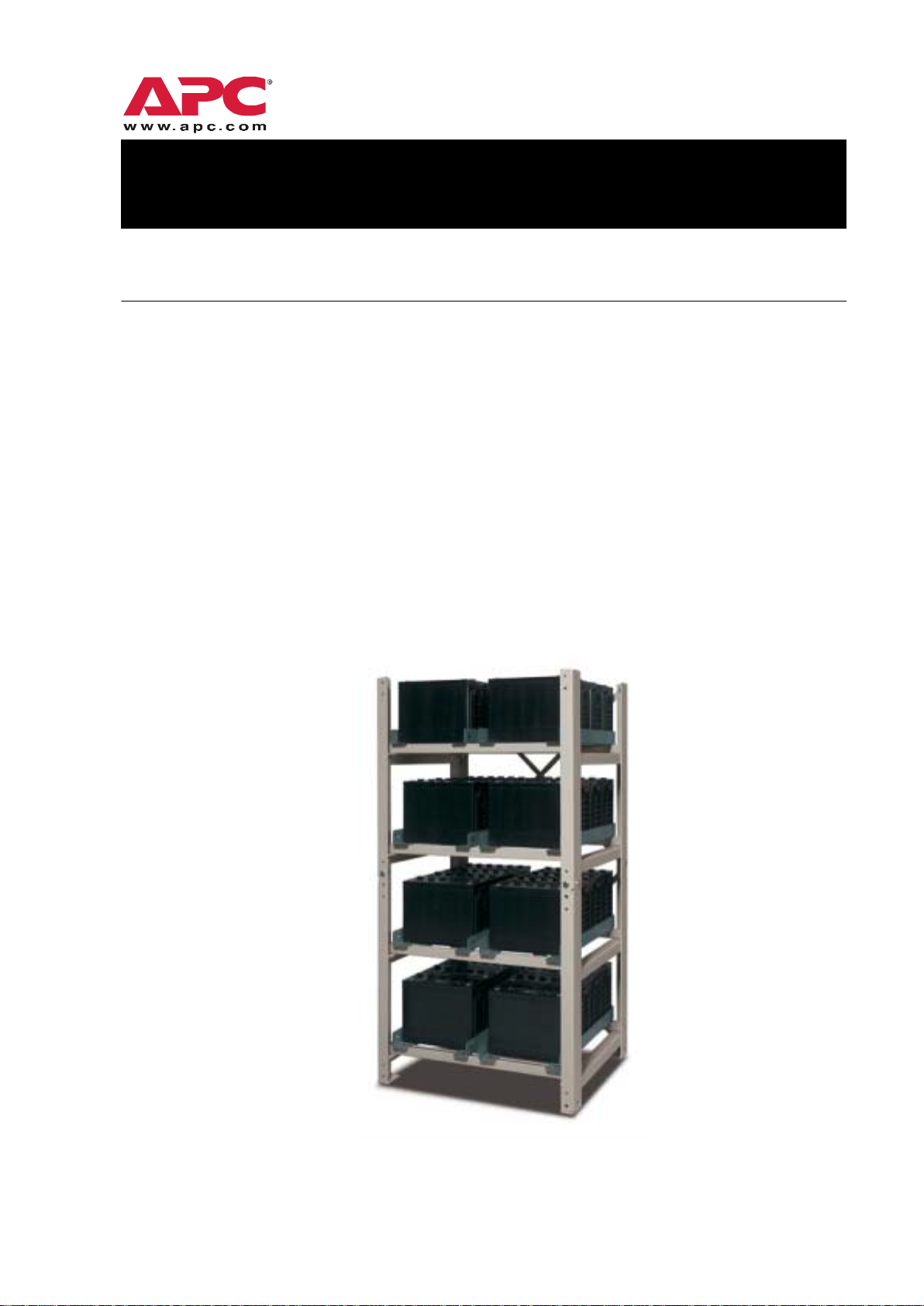
Battery Racks for
400kW–1MW UPS Systems
Assembly and Installation Manual
This manual provides information pertaining to the assembly, loading, and wiring of those APC
battery racks designed to support the following Symmetra
• 400 kW • 800 kW
•600 kW •1 MW
The basic components of each rack consist of frames, cross braces, support rails, and assembly
hardware. Refer to “Parts List” on page 7.
Read these instructions carefully, and observe all safety warnings and other precautions before
assembling racks or installing batteries. Should you require any assembly supervision, service, parts,
accessories or maintenance, call the appropriate APC number (refer to rear of document).
®
MW UPS systems:
Page 2

Battery Rack Assembly and Installation Manual
Page 3

Contents
Safety . . . . . . . . . . . . . . . . . . . . . . . . . . . . . . . . . . . . . . . . . . . . 1
Safety warnings . . . . . . . . . . . . . . . . . . . . . . . . . . . . . . . . 1
Safety precautions . . . . . . . . . . . . . . . . . . . . . . . . . . . . . . . 1
Additional considerations . . . . . . . . . . . . . . . . . . . . . . . . . . 2
Specifications . . . . . . . . . . . . . . . . . . . . . . . . . . . . . . . . . . . . . . 3
Rack/battery options . . . . . . . . . . . . . . . . . . . . . . . . . . . . . 3
Weights and dimensions . . . . . . . . . . . . . . . . . . . . . . . . . . 3
Shipping and Receiving. . . . . . . . . . . . . . . . . . . . . . . . . . . . . . . 4
Shipping . . . . . . . . . . . . . . . . . . . . . . . . . . . . . . . . . . . . . 4
Receiving . . . . . . . . . . . . . . . . . . . . . . . . . . . . . . . . . . . . . 4
Placement . . . . . . . . . . . . . . . . . . . . . . . . . . . . . . . . . . . . . . . . . 5
Positioning . . . . . . . . . . . . . . . . . . . . . . . . . . . . . . . . . . . . 5
Handling . . . . . . . . . . . . . . . . . . . . . . . . . . . . . . . . . . . . . 5
Installation Site . . . . . . . . . . . . . . . . . . . . . . . . . . . . . . . . . . . . . 6
Installation considerations . . . . . . . . . . . . . . . . . . . . . . . . . 6
Installation equipment . . . . . . . . . . . . . . . . . . . . . . . . . . . . 6
Torque specifications . . . . . . . . . . . . . . . . . . . . . . . . . . . . . 6
Parts List . . . . . . . . . . . . . . . . . . . . . . . . . . . . . . . . . . . . . . . . . . 7
Battery Cabling . . . . . . . . . . . . . . . . . . . . . . . . . . . . . . . . . . . . . 8
Battery Rack Assembly and Installation Manual i
Page 4

Rack Assembly. . . . . . . . . . . . . . . . . . . . . . . . . . . . . . . . . . . . . . 9
Assembling the bottom section . . . . . . . . . . . . . . . . . . . . . . 9
Assembling the top section . . . . . . . . . . . . . . . . . . . . . . . . 11
Stabilizing the rack . . . . . . . . . . . . . . . . . . . . . . . . . . . . . 15
Anchoring the rack (optional) . . . . . . . . . . . . . . . . . . . . . . 16
Numbering the batteries . . . . . . . . . . . . . . . . . . . . . . . . . 16
Accessing your wiring diagrams . . . . . . . . . . . . . . . . . . . . 16
Positioning rails on shelves . . . . . . . . . . . . . . . . . . . . . . . . 17
Addressing the bottom shelf . . . . . . . . . . . . . . . . . . . . . . . 17
Wiring the batteries . . . . . . . . . . . . . . . . . . . . . . . . . . . . 18
Addressing the third shelf . . . . . . . . . . . . . . . . . . . . . . . . 21
Addressing the second shelf . . . . . . . . . . . . . . . . . . . . . . . 21
Addressing the top shelf . . . . . . . . . . . . . . . . . . . . . . . . . 22
Shelf-to-shelf wiring . . . . . . . . . . . . . . . . . . . . . . . . . . . . . 23
Assembling the second rack . . . . . . . . . . . . . . . . . . . . . . . 24
Labelling the terminal blocks . . . . . . . . . . . . . . . . . . . . . . 25
Employing sidecars to support separated racks . . . . . . . . . . 25
Connecting terminal blocks to battery breakers . . . . . . . . . . 26
Connecting terminal blocks to batteries . . . . . . . . . . . . . . . 28
Reattaching terminal block covers . . . . . . . . . . . . . . . . . . . 33
Applying warning labels . . . . . . . . . . . . . . . . . . . . . . . . . 33
Grounding the racks . . . . . . . . . . . . . . . . . . . . . . . . . . . . 33
Glossary . . . . . . . . . . . . . . . . . . . . . . . . . . . . . . . . . . . . . . . . . 34
Appendix A: Battery Wiring Style E . . . . . . . . . . . . . . . . . . . . . 35
Style E, rack #1, shelf #1 (top) . . . . . . . . . . . . . . . . . . . . . 35
Style E, rack #1, shelf #2 . . . . . . . . . . . . . . . . . . . . . . . . . 36
Style E, rack #1, shelf #3 . . . . . . . . . . . . . . . . . . . . . . . . . 37
Style E, rack #1, shelf #4 (bottom) . . . . . . . . . . . . . . . . . . . 38
Style E, rack #2, shelf #1 (top) . . . . . . . . . . . . . . . . . . . . . 39
Style E, rack #2, shelf #2 . . . . . . . . . . . . . . . . . . . . . . . . . 40
Style E, rack #2, shelf #3 . . . . . . . . . . . . . . . . . . . . . . . . . 41
Style E, rack #2, shelf #4 (bottom) . . . . . . . . . . . . . . . . . . . 42
Appendix B: Battery Cabling Kits . . . . . . . . . . . . . . . . . . . . . . . 43
References for Power battery cables: . . . . . . . . . . . . . . . . . 43
References for Fiamm battery cables: . . . . . . . . . . . . . . . . . 43
ii Battery Rack Assembly and Installation Manual
Page 5

Appendix C: Employing Sidecars . . . . . . . . . . . . . . . . . . . . . . . 44
Sidecar overview . . . . . . . . . . . . . . . . . . . . . . . . . . . . . . . 44
Positioning and accessing the sidecar . . . . . . . . . . . . . . . . . 45
Connecting terminal blocks to sidecars . . . . . . . . . . . . . . . . 46
Connecting sidecars to battery breakers . . . . . . . . . . . . . . . 50
APC Warranty on Batteries . . . . . . . . . . . . . . . . . . . . . . . . . . . 57
APC Worldwide Customer Support . . . . . . . . . . . . . . . . . . . . . 58
Battery Rack Assembly and Installation Manual iii
Page 6

iv Battery Rack Assembly and Installation Manual
Page 7

Safety
Safety warnings
Warning
• Only QUALIFIED ELECTRICIANS may perform this installation! Battery
installation must be performed in accordance with all applicable codes!
• Observe all WARNING and CAUTION notices! Failure to do so may result in
SERIOUS INJURY or DEATH!
• Disconnect charging source(s) BEFORE connecting or disconnecting battery
terminals!
Electrical
Hazard
• Some battery terminals and other components remain LIVE even when the
• USE EXTREME CAUTION when making terminal connections! DO NOT
• INSULATED TOOLS and proper INSULATING MATERIALS (rubber floor
Safety precautions
• Assemble racks in accordance with the instructions contained in this document
Caution
• For installations where grounding is required for IEC and/or local codes, see
• Refer to local ordinances that pertain to battery installation and storage.
• Handle, transport, and properly dispose of or recycle batteries in accordance
• Lead-acid batteries contain hazardous, toxic materials. DO NOT dispose of
• Do not open, alter, or mutilate batteries! Released electrolyte is harmful to the
• Batteries should always be replaced with the same number and type as
• Batteries must remain in a climate-controlled environment having a
system is switched off! LETHAL VOLTAGES may still be present when the
rack is non-operational, or when breakers are in the OFF position!
allow cables to touch anything except the intended terminal!
stands, rubber mats, gloves, protective clothing, etc.) should be used when
connecting battery cables!
WITHOUT DEVIATION.
instructions for RACK GROUNDING.
with regulations.
batteries in a fire—they may explode!
skin and eyes, and may be toxic.
previously used.
temperature range of 22° to 25° C [72° to 77° F] and a relative humidity of 0%
to 95%, non-condensing. Failure to adhere to these guidelines could adversely
affect the performance of your batteries, as well as your battery warranty.
Battery Rack Assembly and Installation Manual 1
Page 8

Safety
Additional considerations
• Observe all requirements and limitations pertaining to floor loading!
• Remove watches, rings, and other metal objects from your body.
Caution
• DO NOT lay tools or metal parts on top of batteries!
• To avoid static build-up, service personnel should contact ground prior to
working on batteries!
• DO NOT operate battery breakers without first referring to this manual!
2 Battery Rack Assembly and Installation Manual
Page 9

Specifications
Rack/battery options
The racks are deployed in multiples of two, with each rack housing one battery string. A maximum of
eight racks (battery strings) can be used to support a single Symmetra MW UPS. The total number of
strings deployed depends on the customer’s requirements for run-time. The racks can accommodate
either Power or Fiamm battery types.
Refer to “APC Warranty on Batteries” on page 57.
Note
The following product SKUs reflect the currently available rack/battery options.
Rack SKU Battery Type (Model) Assembly
SYR400k1000HxR-2CP Power (TC-12150) 16 rails 2 E 120 mm
SYR400k1000HxR-2CF Fiamm (12SLB130) 16 rails 2 E 120 mm
*Cobra cable rated for 150°C
Qty Wiring Style
Cable Size (ref)*
W e ights and dimensions
Each assembled rack measures 1778mm (H) x 1047mm (W) x 797mm (D) [70” x 41.2” x 31.4”]. For
each two-rack combination, the width doubles to 2094mm [82.4”]. The weight of individual racks,
battery types, and a fully loaded TWO-rack system is presented below.
Rack SKU
SYR400k1000HxR-2CP 156 kg Power (TC-12150) 45 kg 3192 kg
SYR400k1000HxR-2CF 156 kg Fiamm (12SLB130) 42 kg 3000 kg
Weight Per Rack Battery Type Weight Per Batt Total Wgt
2
(#4/0)
2
(#4/0)
Battery Rack Assembly and Installation Manual 3
Page 10

Shipping and Receiving
Shipping
Rack assemblies are shipped in corrugated boxes. Battery cables, battery boots, terminal blocks, and
labels are also included in the shipment. Each pallet can support a maximum of two (2) units. Boxes
are shrink-wrapped to the pallet for added stability.
Batteries are shipped separately, and shrink wrapped to their pallet as well.
Receiving
Check for damages.
1. Upon receipt, inspect the boxes for obvious signs of rough handling.
2. Remove shrink wrap, open boxes, and conduct an internal inspection of the equipment.
Keep boxes on pallet for transportation to installation site.
3. Record any damages and call the carrier immediately to allow their personnel to conduct an
equipment inspection.
– DO NOT contact APC first—notify the carrier instead. Otherwise, APC may be unable to
assist in recovering the realized amount of the claim.
– All damage claims should be as specific as possible. Information pertaining to the shipment
should appear on the shipping label and related paperwork.
– BE SURE to request a copy of the carrier’s inspection report!
Check for discrepancies. Make certain the shipment has arrived in its entirety. Compare
information from the shipping label/parts list against what has been received. If any part is missing or
might have been damaged prior to shipping, contact APC immediately.
4 Battery Rack Assembly and Installation Manual
Page 11
Placement
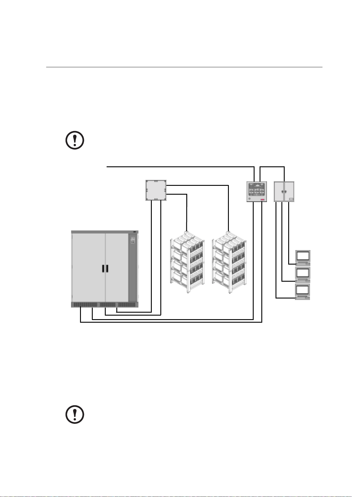
Positioning
The racks should ideally be positioned so that the batteries can easily be connected to the appropriate
breaker in the battery breaker box(es). The graphic below shows a typical UPS system, and how the
battery racks fit into the overall system.
If any or all of the racks are positioned apart from the battery breakers, sidecars
should be employed to achieve connectivity. Sidecars are discussed in detail in
Note
MWA
“Appendix C: Employing Sidecars” on page 44.
Mains Supply
Battery Breaker
Box(es)
UPS
Service
Bypass
Panel
Distribution
Panel
Battery Rack #1
Battery Rack #2
Handling
The rack assemblies are relatively heavy (weighing 156 kg [344 lbs] each), so use a forklift or palletjack to transport boxes (on their pallets!) to the installation site. Upon arrival, re-open the boxes and
remove the assembly equipment. Organize the parts in an area as close as possible to the rack’s final
installation position.
If a rack must be moved or repositioned following assembly (and battery loading),
DO NOT lift (with forklift or pallet-jack) from the front! This could cause
batteries to slide off and might result in rack damage as well! Always lift from the
Note
side of the rack, if possible.
Load
Battery Rack Assembly and Installation Manual 5
Page 12

Installation Site
Installation considerations
The installation site should adhere to the following requirements:
• There should be ample room for performing rack assembly, battery installation, maintenance,
and possible battery replacement.
• Aisle spacing should be in accordance with applicable code requirements.
• Racks should be set on a firm and reasonably level surface. Shimming up to a maximum of
6 mm [0.25 in.] may be used to level corner posts both front-to-ba ck and side-to-side.
• Consider all requirements and restrictions with respect to floor loading.
• Batteries must remain in a climate-controlled environment having a temperature range of 22° to
25° C [72° to 77° F] and a relative humidity of 0% to 95%, non-condensing.
• Batteries should not be exposed to excessive moisture, construction dirt, corrosive elements,
and other contaminants.
Installation equipment
Prior to assembling racks, ensure availability of the following tools and equipment:
• Open end/box wrenches (SAE dimensions) • Battery lifting device (rated)
• Ratchet set w/sockets (SAE dimension)—3/8” • Step ladder or stepping stool
• Torque wrench • Tape measure
• Standard, Phillips, and torx-head screwdrivers • Chalk line
• Concrete drill (for floor anchoring, if applicable) • T-square
• Voltmeter • Level
• Ohmmeter (for ground testing) • Felt tip marker
• Floor shims (user supplied) • Protective boot (to cover cable lugs)
Torque specifications
STANDARD BOLT BATTERY TERMINAL
Bolt Diameter Torque Battery Type Torque
mm inches Nm in-lbs Brand Nm in-lbs
6 1/4 7 60 Power 7.9 70
10 3/8 27 240 Fiamm 11.3 100
12 1/2 68 600
6 Battery Rack Assembly and Installation Manual
Page 13

Parts List
This section provides a listing of parts needed to assemble each battery rack. Do not proceed with this
installation until all parts are in your possession.
Description APC P/N Qty
T o p Side Subassembly 870-1657A 2
Bottom Side Subassembly 870-1658A 2
Battery Rail 870-1696 16
Cross Bar (rack) 870-3698 8
Rear Cross Brace 870-3697 4
M12 x 35 Bolt 803-1235 14
M12 Nut 803-1200 14
12mm Lockwasher 812-0038 14
12mm W asher 812-0039 28
1/4-20 Spring Nut 812-0040 32
1/4-20 x 3/4” Socket Flathead Screw 812-0037 32
3/8-16 x 1” Bolt 812-0723 16
3/8 KEPS Nut 812-3101 16
3/8 Washer 812-2030 32
M6 Flange Nut 803-2406 1
M6 Serrated Wash er 811-0604 1
Number Sheet Label 885-1617 1
Warning Label 4
CE Rating Label 885-1618 1
Battery Rack Assembly and Installation Manual 7
Page 14

Battery Cabling
Batteries are arranged in the rack in accordance with Wiring Style E. The wiring diagrams for this
style are detailed in “Appendix A: Battery Wiring Style E” on page 35.
The (included) battery cabling kit was designed to suit the specific requirements of your product
SKU. The cable references for this kit are provided in “Appendix B: Battery Cabling Kits” on
page 43. If your kit is missing cables, contact APC immediately . Do not proceed with this installation
until all parts are in your possession.
8 Battery Rack Assembly and Installation Manual
Page 15
Rack Assembly
Assembling the bottom section
The bottom section of the rack will contain shelves #3 and #4.
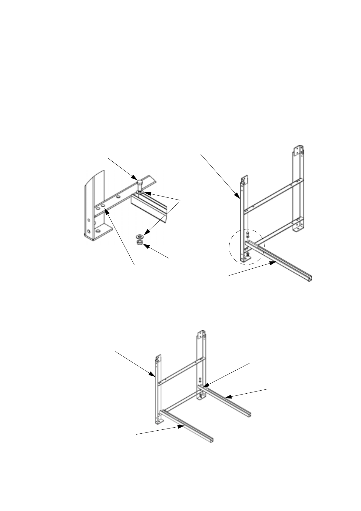
1. Bolt Cross Bar #1 to Bottom Side Subassembly #1 at hole position #2 (from front) on the
LOWER horizontal support of the Subassembly. Use (1) 3/8-1 6 x 1” bolt an d related hardware:
(2) 3/8 washers and (1) 3/8 KEPS nut.
3/8-16 x 1” Bolt
(812-0723)
Hole Position #2
from Front
Bottom Side Subassembly #1
(870-1658A)
3
3
3
3/8
3
3/8 Washers
(812-2030)
3/8 KEPS Nut
(812-3101)
3
Cross Bar #1
(870-3698)
2. Bolt Cross Bar #2 to Bottom Side Subassembly #1 at hole position #6 (from front) on the
LOWER horizontal support of the Subassembly. Use (1) 3/8-1 6 x 1” bolt an d related hardware:
(2) 3/8 washers and (1) 3/8 KEPS nut.
Bottom Side Subassembly #1
Cross Bar #1
Hole Position #6
from Front
Cross Bar #2
(870-3698)
Battery Rack Assembly and Installation Manual 9
Page 16

Rack Assembly
3. Bolt Cross Bar #1 to Bottom Side Subassembly #2 at its opposite hole position #2 (from front).
Use (1) 3/8-16 x 1” bolt and related hardware: (2) 3/8 washers and (1) 3/8 KEPS nut.
Refer to graphic in step 4 below.
4. Bolt Cross Bar #2 to Bottom Side Subassembly #2 at its opposite hole position #6 (from front).
Use (1) 3/8-16 x 1” bolt and related hardware: (2) 3/8 washers and (1) 3/8 KEPS nut.
Bottom Side Subassembly #1
Cross Bar #1
STEP 3 Connection
Cross Bar #2
Bottom Side Subassembly #2
(870-1658A)
STEP 4 Connection
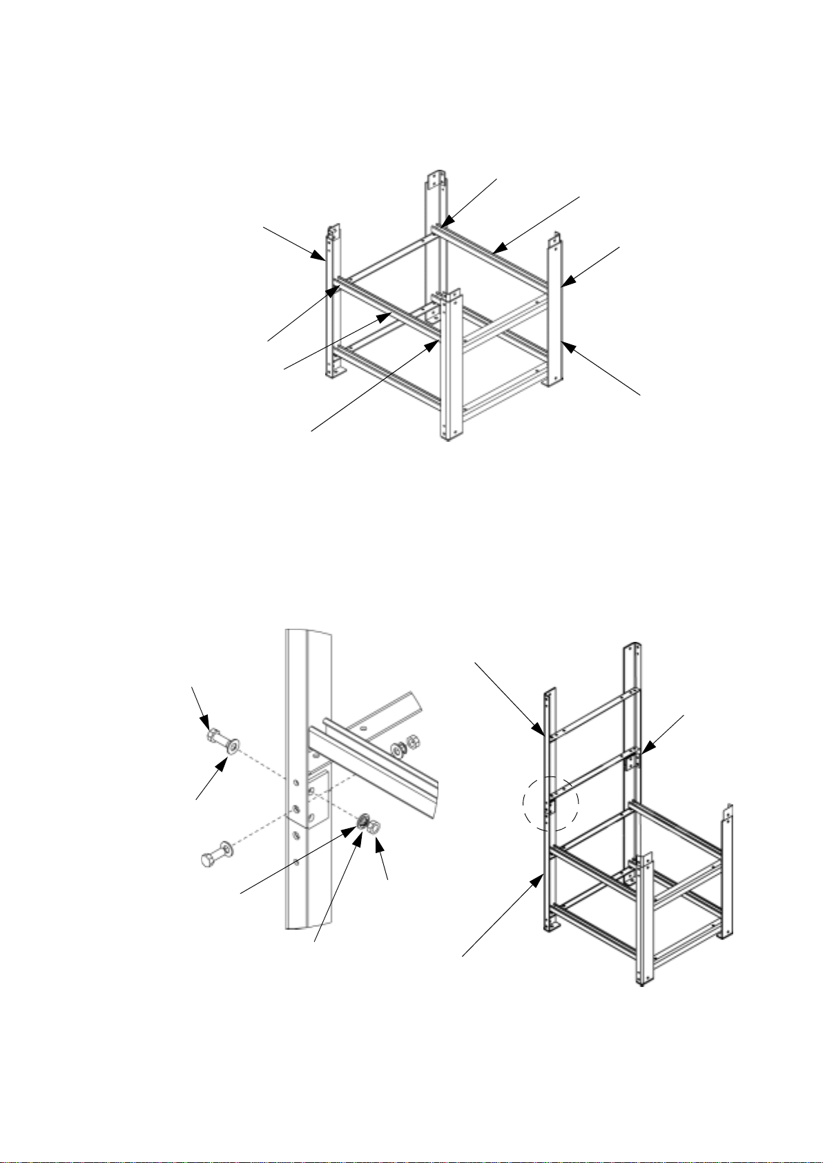
5. Use a T-square to ensure exact right angles between Cross Bars and horizontal supports at all
four corners of the rack before proceeding.
6. Bolt Cross Bar #3 to Bottom Side Subassembly #1 at hole position #2 (from front) on the
UPPER horizontal support of the Subassembly. Use (1) 3/8-16 x 1” bolt and related hardware:
(2) 3/8 washers and (1) 3/8 KEPS nut.
Refer to graphic in step 9 below.
7. Bolt Cross Bar #3 to Bottom Side Subassembly #2 at its opposite hole position #2 (from front).
Use (1) 3/8-16 x 1” bolt and related hardware: (2) 3/8 washers and (1) 3/8 KEPS nut.
Refer to graphic in step 9 below
8. Bolt Cross Bar #4 to Bottom Side Subassembly #1 at hole position #6 (from front) on the
UPPER horizontal support of the Subassembly. Use (1) 3/8-16 x 1” bolt and related hardware:
(2) 3/8 washers and (1) 3/8 KEPS nut.
Refer to graphic in step 9 below.
10 Battery Rack Assembly and Installation Manual
Page 17
Rack Assembly
9. Bolt Cross Bar #4 to Bottom Side Subassembly #2 at its opposite hole position #6 (from front).
Use (1) 3/8-16 x 1” bolt and related hardware: (2) 3/8 washers and (1) 3/8 KEPS nut.
STEP 8 Connection
Cross Bar #4
(870-3698)
Bottom Side Subassembly #1
STEP 9 Connection
STEP 6 Connection
Cross Bar #3
(870-3698)
Bottom Side Subassembly #2
STEP 7 Connection
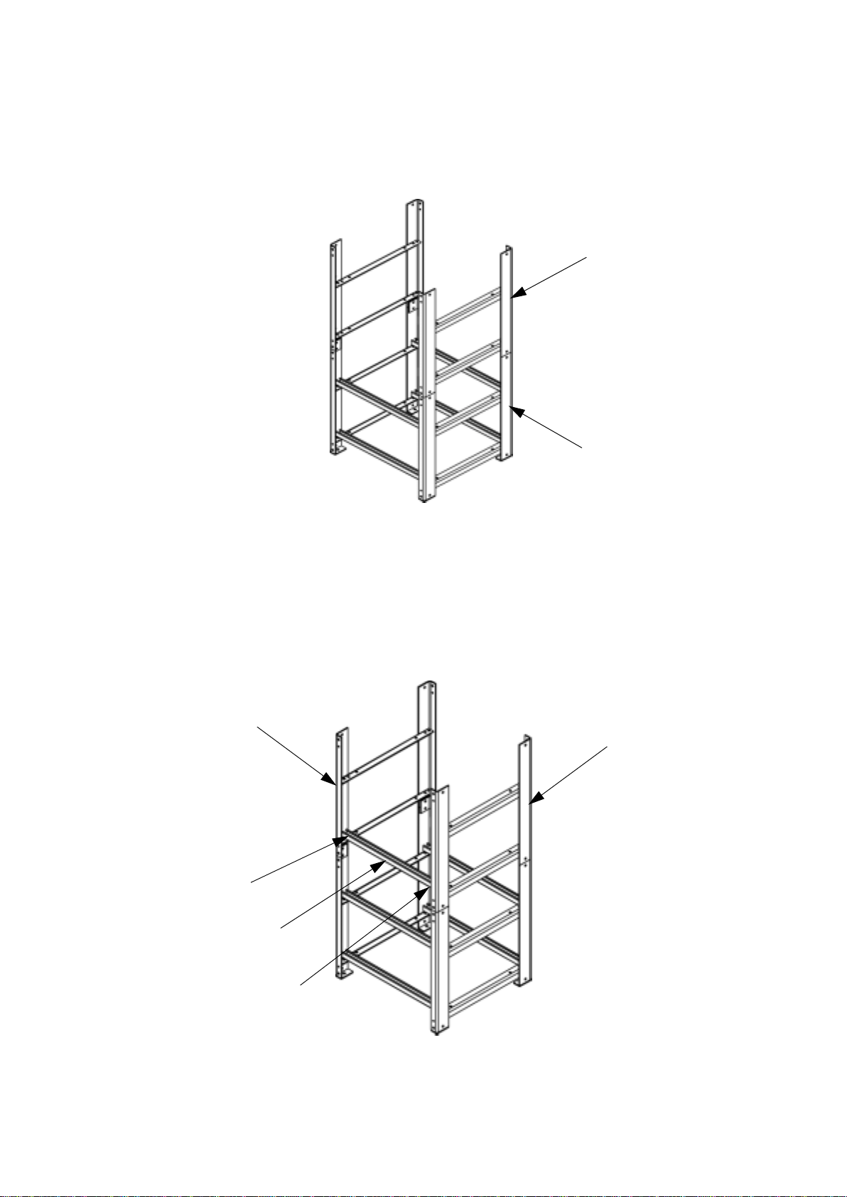
Assembling the top section
The top section of the rack will contain shelves #1 and #2.
1. Bolt Top Side Subassembly #1 onto Bottom Side Subassembly #1 at designated hole positions.
Use (3) M12 x 35 bolts and related hardware: (6) 12mm washers, (3) 12mm lockwashers and
(3) M12 nuts. DO NOT bolt the REAR hole at this time!
Top Side Subassembly #1
M12 x 35 Bolt
(803-1235)
12mm Washer
(812-0039)
12mm Washer
(812-0039)
M12 Nut
(803-1200)
(870-1657A)
DO NOT
BOLT HERE!
12mm Lockwasher
(812-0038)
Battery Rack Assembly and Installation Manual 11
Bottom Side Subassembly #1
Page 18
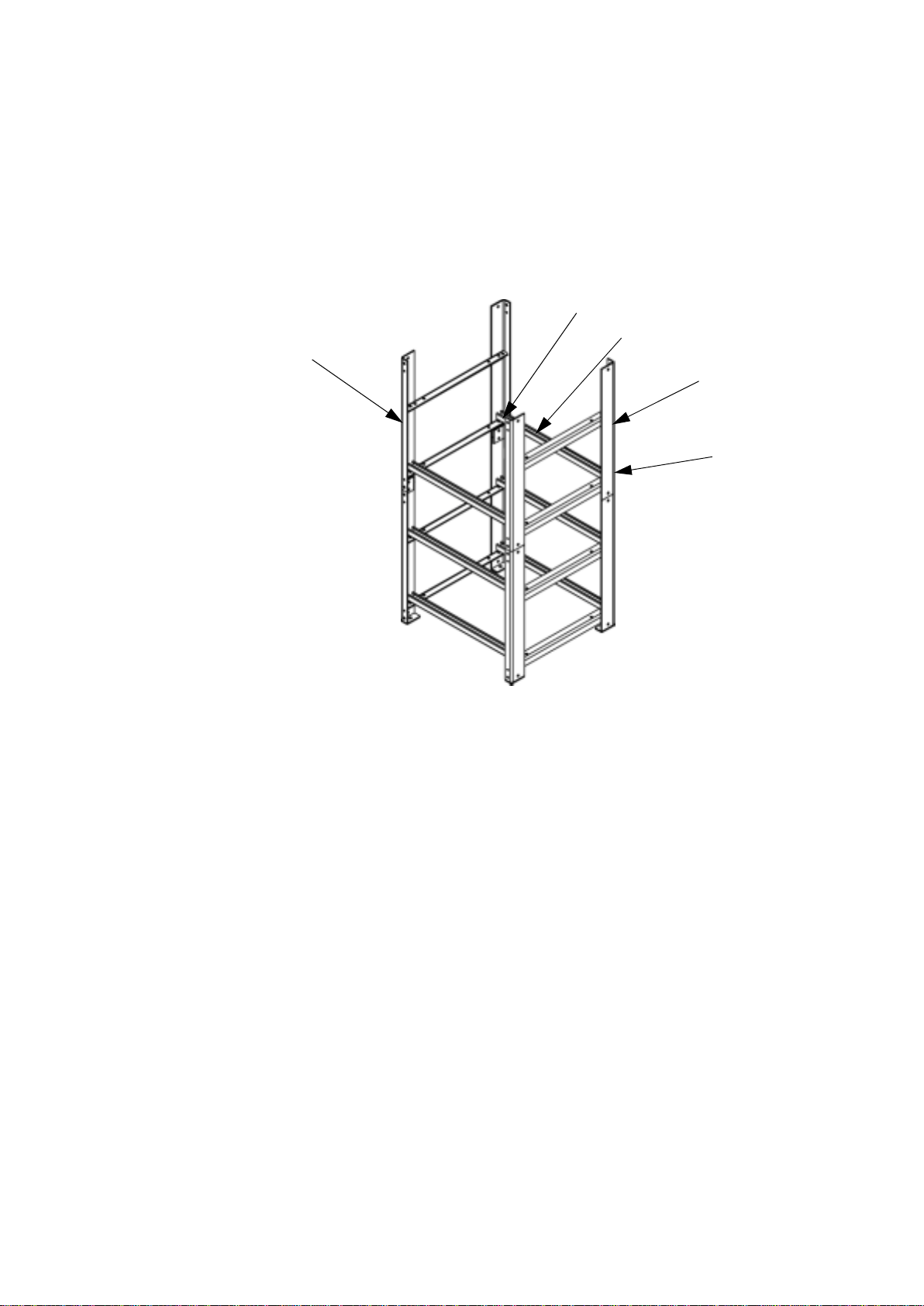
Rack Assembly
2. Bolt Top Side Subassembly #2 onto Bottom Side Subassembly #2 at same basic hole positions
specified in step 1 above. Use (3) M12 x 35 bolts and related hardware: (6) 12mm washers, (3)
12mm lockwashers and (3) M12 nuts. Again, DO NOT bolt REAR hole!
Top Side Subassembly #2
(870-1657A)
Bottom Side Subassembly #2
3. Bolt Cross Bar #5 to Top Side Subassembly #1 at hole position #2 (from front) on the LOWER
horizontal support of the Subassembly. Use (1) 3/8-16 x 1” bolt and related hardware:
(2) 3/8 washers and (1) 3/8 KEPS nut.
Refer to graphic in step 4 below.
4. Bolt Cross Bar #5 to Top Side Subassembly #2 at its opposite hole position #2 (from front). Use
(1) 3/8-16 x 1” bolt and related hardware: (2) 3/8 washers and (1) 3/8 KEPS nut.
Top Side Subassembly #1
Top Side Subassembly #2
STEP 3 Connection
Cross Bar #5
(870-3698)
STEP 4 Connection
12 Battery Rack Assembly and Installation Manual
Page 19
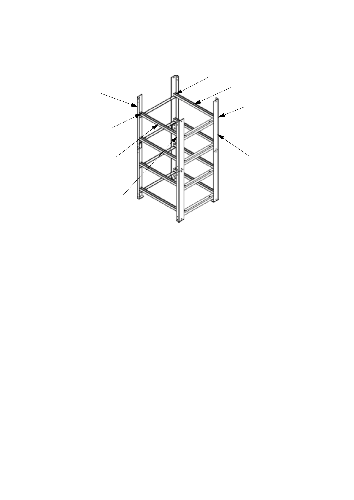
Rack Assembly
5. Bolt Cross Bar #6 to Top Side Subassembly #1 at hole position #6 (from front) on the LOWER
horizontal support of the Subassembly. Use (1) 3/8-16 x 1” bolt and related hardware: (2) 3/8
washers and (1) 3/8 KEPS nut.
Refer to graphic in step 6 below.
6. Bolt Cross Bar #6 to Top Side Subassembly #2 at its opposite hole position #6 (from front). Use
(1) 3/8-16 x 1” bolt and related hardware: (2) 3/8 washers and (1) 3/8 KEPS nut.
STEP 5 Connection
Cross Bar #6
Top Side Subassembly #1
(870-3698)
Top Side Subassembly #2
STEP 6 Connection
7. Bolt Cross Bar #7 to Top Side Subassembly #1 at hole position #2 (from front) on the UPPER
horizontal support of the Subassembly. Use (1) 3/8-16 x 1” bolt and related hardware: (2) 3/8
washers and (1) 3/8 KEPS nut.
Refer to graphic in step 10 below.
8. Bolt Cross Bar #7 to Top Side Subassembly #2 at its opposite hole position #2 (from front). Use
(1) 3/8-16 x 1” bolt and related hardware: (2) 3/8 washers and (1) 3/8 KEPS nut.
Refer to graphic in step 10 below.
9. Bolt Cross Bar #8 to Top Side Subassembly #1 at hole position #6 (from front) on the UPPER
horizontal support of the Subassembly. Use (1) 3/8-16 x 1” bolt and related hardware: (2) 3/8
washers and (1) 3/8 KEPS nut.
Refer to graphic in step 10 below.
Battery Rack Assembly and Installation Manual 13
Page 20
Rack Assembly
10.Bolt Cross Bar #8 to T op Side Subassembly #2 at its opposite hole position #6 (from front). Use
(1) 3/8-16 x 1” bolt and related hardware: (2) 3/8 washers and (1) 3/8 KEPS nut.
Top Side Subassembly #1
STEP 7 Connection
STEP 9 Connection
Cross Bar #8
(870-3698)
STEP 10 Connection
Cross Bar #7
(870-3698)
STEP 8 Connection
Top Side Subassembly #1
14 Battery Rack Assembly and Installation Manual
Page 21

Stabilizing the rack
Bolt (4) Rear Cross Braces to rack at designated hole positions. Use (8) M12 x 35 bolts and related
hardware: (16) 12mm washers, (8) 12mm lockwashers and (8) M12 nuts. Note that lower bolts on
Brace #1 and Brace #2 also connect the Top Side Assemblies to the Bottom Side Assemblies.
Rack Assembly
Top Side Assembly #2
Rear Cross Brace #1
Rear Cross Brace #3
Bottom Side Assembly #2
12mm Lockwasher
(812-0038)
(870-3697)
(870-3697)
12mm Washers
(812-0039)
REAR OF RACK
M12 x 35 Bolt
(803-1235)
Top Side Assembly #1
Rear Cross Brace #2
(870-3697)
Rear Cross Brace #4
(870-3698)
Bottom Side Assembly #1
M12 Nut
(803-1200)
Battery Rack Assembly and Installation Manual 15
Page 22

Rack Assembly
Anchoring the rack (optional)
For added stability, any or all of the racks can optionally be bolted to a concrete floor.
T o anchor the rack, chalk mark four (4) pre- cut holes (at the base of the assembly) in the facility floor,
drill, and apply anchoring hardware (not supplied).
Graphic provides accurate dimensional data between hole locations.
996.6
[39.24]
694.8
[27.35]
1047.4
[41.24]
795.5
[31.36]
Numbering the batteries
Each battery is numbered from 1 to 64 because batteries are ultimately wired together in numerical
sequence.
Apply a “numerical” sticker from supplied Labels to the top of each battery to designate its position
in the wiring scheme.
Place a numbered sticker on all 64 of your batteries at this time.
(mm [in])
Accessing your wiring diagrams
Wiring diagrams applicable to your rack SKU shou ld be used as points of reference when loading and
connecting batteries.
Refer to “Appendix A: Battery Wiring Style E” on page 35 throughout the process of loading and
wiring your batteries.
16 Battery Rack Assembly and Installation Manual
Page 23

Positioning rails on shelves
Apply your Battery Type (Power or Fiamm) to the Rail Spacing Matrix below to determine initial
positioning of rails. Take into consideration that this information represents “suggested” starting
points for placing rails. Make adjustments as necessary.
Rack Assembly
Battery
Type
Power E 4 50 2.00 345 13.50 235 9.25
Fiamm E 4 50 2.00 405 16.00 110 4.25
Wiring
Style
Rails/Shelf
Left Corner Post
to 1st Rail
mm in mm in mm in
Space Between
Facing Rails Center Space
Addressing the bottom shelf
To maintain structural integrity, batteries are loaded from bottom-to-top in the rack.
1. Position Battery Rails on BOTTOM shelf Cross Bars according to spacing requirements
obtained from the Rail Spacing Matrix chart above. Measure with ruler or tape to ensure proper
spacing, and later make adjustments as necessary.
Each “set” of two (2) rails should face inward to enable their facing edges to support batteries.
Refer to graphic in step 2 below.
2. Screw Battery Rails into BOTTOM shelf Cross Bars using 1/4-20 x 3/4” flathead screws and
1/4-20 spring nuts. Each battery rail requires two screws and two spring nu ts (on e screw and
spring nut is applied to each cross bar).
Battery Rail
(870-1696)
1/4-20 x 3/4” Flathead
Screw (812-0037)
1/4-20 Spring Nut
(812-0040)
Cross Bar
Battery Rack Assembly and Installation Manual 17
Page 24

Rack Assembly
3. Using a rated lifting device, load batteries onto BOTTOM shelf rails in accordance with your
wiring diagram for that shelf. Take note of where each numbered battery should be placed, and
the proper positioning of its positive and negative terminals.
• Because batteries are loaded from bottom-to-top in the rack, the highernumbered batteries are placed on the lower shelves.
Note
• Prior to loading batteries, use a voltmeter to ensure each battery contains its
required 12V. DO NOT load any battery with an insufficient voltage!
Leave a minimum space of 5 mm (.2 in) between batteries in the same row.
28
27
26
Positive Terminal Negative Terminal
5 mm [.2]
5 mm [.2]
Wiring the batteries
All of the batteries loaded onto a given shelf must be connected (wired) in numerical sequence before
starting assembly of the next shelf. These connections consist of battery-to-battery and row-to-row
wiring.
Review “Safety” on page 1 for safety warnings and caution notices. Take heed of
all safety information before proceeding with battery connections. Failure to
Warning
comply could result in serious injury or death!
1. Connect all batteries in the same row (those on the same rails) using the supplied battery-tobattery cable.
– Refer to your wiring diagrams for proper cabling and termination points.
– Refer to instructions for “Applying cable boots” on page 19, “Connecting to batteries” on
page 20, and “Covering battery connections” on page 21.
• Prior to connecting batteries, use a voltmeter to check the voltage between
those terminals being connected. Any reading other than zero is unacceptable.
Note
• After connecting each row, use voltmeter to measure the collective voltage.
Reading should approximate number of batteries in row times 12V.
18 Battery Rack Assembly and Installation Manual
Page 25

Rack Assembly
2. Working left to right (from front of rack), connect the last battery in the first row to the first
battery in the second row using the supplied row-to-row cable.
– Refer to your wiring diagrams for proper cabling and termination points.
– Refer to instructions for “Applying cable boots” on this page, “Connecting to batteries” on
page 20, and “Covering battery connections” on page 21.
• Prior to connecting batteries, use a voltmeter to check the voltage between
those terminals being connected. Any reading other than zero is unacceptable.
Note
• After connecting the entire shelf, use voltmeter to measure the collective
voltage. Reading should approximate number of batteries on shelf times 12V.
Applying cable boots. Before wiring batteries, slide both cable ends through a cable boot.
Battery Rack Assembly and Installation Manual 19
Page 26

Rack Assembly
Connecting to batteries. There are three types of battery terminals for connecting cables: 1) Stud
terminal, 2) Insert terminal, and 3) L (or I) terminal. The application of hardware for making the
connection varies according to the type of terminal. Refer to “Torque specifications” on page 6.
• Stud Terminal
mwa
Stud
Stud
Lockwasher
Cable Lug
Nut
Washer
• Insert Terminal
Bolt
Insert
Lockwasher
Washer
Cable Lug
• L or I Terminal
MWA
L-shape
Washer
Lockwasher
Nut
Bolt
Washer
Cable Lug
20 Battery Rack Assembly and Installation Manual
Page 27

Rack Assembly
Covering battery connections. After each lug has been connected to its battery terminal, snap the
boot down over the lug/terminal.
Addressing the third shelf
The THIRD shelf is addressed only after bottom shelf batteries have been loaded and wired.
1. Position Battery Rails on THIRD shelf Cross Bars according to spacing requirements obtained
from the Rail Spacing Matrix on page 17. Measure with ruler or tape to ensure proper spacing,
and later make adjustments as necessary.
Refer to step 1 on page 17 for similar procedure.
2. Screw Battery Rails into THIRD shelf Cross Bars using 1/4-20 x 3/4” flathead screws and
1/4-20 spring nuts. Each battery rail requires two screws and two spring nu ts (on e screw and
spring nut is applied to each cross bar).
Refer to step 2 on page 17 for similar procedure.
3. Using a rated lifting device, load batteries onto THIRD shelf rails in accordance with your
wiring diagram. Take note of where each numbered battery should be placed, and the proper
positioning of its positive and negative terminals.
Refer to step 3 on page 18 for similar procedure.
4. Make all specified THIRD shelf battery-to-battery and row-to-row connections.
Refer to “Wiring the batteries” on page 18.
Addressing the second shelf
The SECOND shelf is addressed only after third shelf batteries have been loaded and wired.
1. Position Battery Rails on SECOND shelf Cross Bars according to spacing requirements
obtained from the Rail Spacing Matrix on page 17. Measure with ruler or tape to ensure proper
spacing, and later make adjustments as necessary.
Refer to step 1 on page 17 for similar procedure.
Battery Rack Assembly and Installation Manual 21
Page 28

Rack Assembly
2. Screw (1) Terminal Block Assembly to the SECOND shelf Cross Bar at the front of the rack.
Secure to cross bar with the (2) supplied M6 socket-head cap screws and flange nuts.
Select a location on the bar that does not conflict with battery or rail placement. The end stops
can be loosened to allow the block to move left or right on its assembly.
Cross Bar
M6 Socket-head Cap Screws
TERMINAL
t
TER
TERMINAL
TER
End Stops
t
Terminal Block
3. Screw Battery Rails into SECOND shelf Cross Bars using 1/4-20 x 3/4” flathead screws and
1/4-20 spring nuts. Each battery rail requires two screws and two spring nuts (one screw and
spring nut is applied to each cross bar).
Refer to step 2 on page 17 for similar procedure.
4. Using a rated lifting device, load batteries onto SECOND shelf rails in accordance with your
wiring diagram. Take note of where each numbered battery should be placed, and the proper
positioning of its positive and negative terminals.
Refer to step 3 on page 18 for similar procedure.
5. Make all specified SECOND shelf battery-to-battery and row-to-row connections.
Refer to “Wiring the batteries” on page 18.
Addressing the top shelf
The TOP shelf is addressed only after second shelf batteries have been loaded and wired.
1. Position Battery Rails on TOP shelf Cross Bars according to spacing requirements obtained
from the Rail Spacing Matrix on page 17. Measure with ruler or tape to ensure proper spacing,
and later make adjustments as necessary.
Refer to step 1 on page 17 for similar procedure.
2. Screw Battery Rails into TOP shelf Cross Bars using 1/4-20 x 3/4” flathead screws and 1/4-20
spring nuts. Each battery rail requires two screws and two spring nuts (one screw and spring nut
is applied to each cross bar).
Refer to step 2 on page 17 for similar procedure.
22 Battery Rack Assembly and Installation Manual
Page 29

Rack Assembly
3. Using a rated lifting device, load batteries onto TOP shelf rails in accordance with your wiring
diagram. Take note of where each numbered battery should be placed, and the proper
positioning of its positive and negative terminals.
Refer to step 3 on page 18 for similar procedure.
4. Make all specified TOP shelf battery-to-battery and row-to-row connections.
Refer to “Wiring the batteries” on page 18.
Shelf-to-shelf wiring
Shelf-to-shelf wiring takes place after ALL of the shelves in your rack have been fully assembled and
their batteries wired together in numerical sequence. Start with the top shelf and work down.
Review “Safety” on page 1 for safety warnings and caution notices. Take heed of
all safety information before proceeding with battery connections. Failure to
Warning
comply could result in serious injury or death!
Using the supplied shelf-to-shelf cable, connect the HIGHEST-numbered battery on the TOP shelf to
the LOWEST-numbered battery on the SECOND shelf. Then connect the highest-numbered battery
on the second shelf to the lowest-numbered battery on the third shelf. Finally, connect the highestnumbered battery on the third shelf to the lowest-numbered battery on the fourth shelf.
Prior to connecting batteries, use a voltmeter to check the voltage between those
terminals being connected. Any reading other than zero is unacceptable.
Note
Follow these steps for each shelf-to-shelf connection:
1. Refer to your wiring diagrams for proper cabling and termination points.
2. Before making connections, apply two (2) cable boots.
3. Connect one cable end to the open negative (-) terminal on the last battery in the upper shelf.
Snap cable boot over the connected lug/terminal.
4. Apply a “protective” boot (not supplied) to the other cable end, then snake the cable
downward through (space in) centrally located rails.
Boot Your Cable!!!
Battery Rack Assembly and Installation Manual 23
Page 30

Rack Assembly
5. Remove protective boot and connect this same cable end to the open positive (+) terminal on the
first battery in the lower shelf. Snap cable boot over connected lug/terminal.
Shelf-to-shelf Wiring
4
3
2
1
Top Shelf
Assembling the second rack
8
7
6
5
12
11
10
9
2nd Shelf
16
15
14
13
The battery racks must be deployed in multiples of two.
Repeat all previous steps to assemble, load, and wire the second battery rack.
The first rack (Rack #1) contains the BAT 1 string (batteries #1-32), and the second rack
(Rack #2) contains the BAT 2 string (batteries #33-64).
24 Battery Rack Assembly and Installation Manual
Page 31

Labelling the terminal blocks
Each rack is equipped with (1) terminal block assembly. The left (+) and right (-) segments of each
terminal block must be appropriately labelled.
1. Remove the snap-off cover from the front face of each terminal block.
2. Apply two “terminal block” stickers from supplied labels to the partitions on the sides of each
terminal block.
Apply the BAT 1+ (on the left) and BAT 1- (on the right) stickers to the Rack #1 terminal block
(Terminal Block #1), and the BAT 2+ (on the left) and BAT 2- (on the right) stickers to the
Rack #2 terminal block (Te rminal Block #2).
BAT 1+
+
-
Rack Assembly
BAT 1-
Terminal Block #1
BAT 2+
+
Terminal Block #2
-
Employing sidecars to support separated racks
When battery racks are situated apart from their respective battery breakers, sidecars should be
employed to enhance connectivity between the batteries and the breakers.
If racks are NOT separated and sidecars are NOT used, proceed to the next
section below. If racks ARE separated and sidecars ARE used, disregard the next
Note
section and proceed instead to “Appendix C: Employing Sidecars” on page 44.
BAT 2-
Battery Rack Assembly and Installation Manual 25
Page 32

Rack Assembly
Connecting terminal blocks to battery breakers
To minimize risk, terminal block-to-battery breaker connections are made prior to battery-to-
2
terminal block connections. TOP entry of 120 mm
[#4/0] cable (not supplied) is recommended for
all connections specified in this section. Each terminal block assembly contains preset hardware for
securing cable lugs.
Be certain battery breakers are in the open (or OFF) position before making
Electrical
Hazard
connections to them.
All external cable must comply with European and local electrical code.
Note
1. Using one (1) 120 mm
2
[#4/0] cable, connect the appropriate (top or bottom) BAT 1+
terminal in Terminal Block #1 to the BAT 1+ terminal in Battery Breaker #1.
At Terminal Block #1: If using top cable entry, connect to top terminal (as shown) of the BAT
1+ segment on left. Otherwise, connect to bottom terminal. Secure lug to stud with preset
washer and nut. To relieve strain, zip tie cable to the shelf directly above the terminal block.
To Battery Breaker #1
(BAT 1+ terminal)
+
Terminal Block #1
-
At Battery Breaker #1: Refer to the battery breaker’s wiring diagram for the proper BAT 1+ lug
landing on the other end of this cable.
26 Battery Rack Assembly and Installation Manual
Page 33

Rack Assembly
2. Using one (1) 120 mm2 [#4/0] cable, connect the appropriate (top or bottom) BAT 1terminal in Terminal Block #1 to the BAT 1- terminal in Battery Breaker #1.
At Terminal Block #1: If using top cable entry, connect to top terminal (as shown) of the BAT
1- segment on right. Otherwise, connect to bottom terminal. Secure lug to stud with preset
washer and nut. To relieve strain, zip tie cable to the shelf directly above the terminal block.
To Battery Breaker #1
(BAT 1- terminal)
+
Terminal Block #1
At Battery Breaker #1: Refer to the battery breaker’s wiring diagram for the proper BAT 1- lug
landing on the other end of this cable.
3. Using one (1) 120 mm
terminal in Terminal Block #2 to the BAT 2+ terminal in Battery Breaker #2.
At Terminal Block #2: If using top cable entry, connect to top terminal (as shown) of the BAT
2+ segment on left. Otherwise, connect to bottom terminal. Secure lug to stud with preset
washer and nut. To relieve strain, zip tie cable to the shelf directly above the terminal block.
2
[#4/0] cable, connect the appropriate (top or bottom) BAT 2+
To Battery Breaker #2
(BAT 2+ terminal)
-
+
Terminal Block #2
At Battery Breaker #2: Refer to the battery breaker’s wiring diagram for the proper BAT 2+ lug
landing on the other end of this cable.
Battery Rack Assembly and Installation Manual 27
-
Page 34

Rack Assembly
4. Using one (1) 120 mm2 [#4/0] cable, connect the appropriate (top or bottom) BAT 2terminal in Terminal Block #2 to the BAT 2- terminal in Battery Breaker #2.
At Terminal Block #2: If using top cable entry, connect to top terminal (as shown) of the BAT
2- segment on right. Otherwise, connect to bottom terminal. Secure lug to stud with preset
washer and nut. To relieve strain, zip tie cable to the shelf directly above the terminal block.
To Battery Breaker #2
(BAT 2- terminal)
+
Terminal Block #2
-
At Battery Breaker #2: Refer to the battery breaker’s wiring diagram for the proper BAT 2- lug
landing on the other end of this cable.
Connecting terminal blocks to batteries
To m i nimize risk, connections between terminal blocks and batteries should be made FROM the
terminal blocks TO the batteries. 120 mm
2
[#4/0] cable is supplied for all connections specified in
this section. Each terminal block assembly contains preset hardware for securing cable lugs.
Review “Safety” on page 1 for safety warnings and caution notices. Take heed of
all safety information before proceeding with battery connections. Failure to
Warning
comply could result in serious injury or death!
Prior to making connections, use a voltmeter to measure collective voltage of the
BAT 1 (#1-32) and BAT 2 (#33-64) strings. Readings should approximate the
Note
number of batteries in each string times 12V (or about 386V per string).
28 Battery Rack Assembly and Installation Manual
Page 35

Rack Assembly
1. Using specified cable, connect the open BA T 1+ terminal in Terminal Block #1 to the open
positive (+) terminal on Battery #1. Before making connections, apply ONE cable boot. If lug
sizes are different, apply boot to the cable end with the SMALLER lug.
At Terminal Block #1: Connect the lug on the cable end WITHOUT the boot to the open BAT
1+ terminal. Secure lug to stud with preset washer and nut. Snake cable end WITH the boot
between centrally located rails until it reaches Battery #1.
At Battery #1: Connect the lug on the cable end WITH the boot to the open positive (+) terminal
on Battery #1. Snap the boot over the connected lug/terminal. Use zip ties as needed to relieve
cable strain.
shelf-to-shelf
4
8
to Battery #9
Terminal Block #1
3
2
1
Rack #1, Top Shelf
7
6
5
+
Battery Rack Assembly and Installation Manual 29
-
Page 36

Rack Assembly
2. Using specified cable, connect the open BAT 1- terminal in Terminal Block #1 to the open
negative (-) terminal on Battery #32. Before making connections, apply ONE cable boot. If
lug sizes are different, apply boot to the cable end with the SMALLER lug.
At Terminal Block #1: Connect the lug on the cable end WITHOUT the boot to the open BAT
1- terminal. Secure lug to stud with preset washer and nut. Snake cable end WITH the boot
between centrally located rails until it reaches Battery #32.
At Battery #32: Connect the lug on the cable end WITH the boot to the open negative (-)
terminal on Battery #32. Snap the boot over the connected lug/terminal. Use zip ties as needed
to relieve cable strain.
shelf-to-shelf
from Battery #24
Terminal Block #1
28
27
26
25
32
31
30
29
Rack #1, Bottom Shelf
+
30 Battery Rack Assembly and Installation Manual
-
Page 37

Rack Assembly
3. Using specified cable, connect the open BA T 2+ terminal in Terminal Block #2 to the open
positive (+) terminal on Battery #33. Before making connections, apply ONE cable boot. If
lug sizes are different, apply boot to the cable end with the SMALLER lug.
At Terminal Block #2: Connect the lug on the cable end WITHOUT the boot to the open BAT
2+ terminal. Secure lug to stud with preset washer and nut. Snake cable end WITH the boot
between centrally located rails until it reaches Battery #33.
At Battery #33: Connect the lug on the cable end WITH the boot to the open positive (+)
terminal on Battery #33. Snap the boot over the connected lug/terminal. Use zip ties as needed
to relieve cable strain.
shelf-to-shelf
36
40
to Battery #41
Terminal Block #2
35
34
33
39
38
37
Rack #2, Top Shelf
+
Battery Rack Assembly and Installation Manual 31
-
Page 38

Rack Assembly
4. Using specified cable, connect the open BAT 2- terminal in Terminal Block #2 to the open
negative (-) terminal on Battery #64. Before making connections, apply ONE cable boot. If
lug sizes are different, apply boot to the cable end with the SMALLER lug.
At Terminal Block #2: Connect the lug on the cable end WITHOUT the boot to the open BAT
2- terminal. Secure lug to stud with preset washer and nut. Snake cable end WITH the boot
between centrally located rails until it reaches Battery #64.
At Battery #64: Connect the lug on the cable end WITH the boot to the open negative (-)
terminal on Battery #64. Snap the boot over the connected lug/terminal. Use zip ties as needed
to relieve cable strain.
shelf-to-shelf
from Battery #56
Terminal Block #2
60
59
58
57
64
63
62
61
Rack #2, Bottom Shelf
+
32 Battery Rack Assembly and Installation Manual
-
Page 39

Rack Assembly
Reattaching terminal block covers
Reattach the snap-off cover to the front face of each terminal block.
Applying warning labels
Labels must be applied to the more visible areas of the racks to warn of the dangers associated with
live batteries.
1. Apply supplied “Warning” Labels to the front-facing Cross Bar on each shelf in the battery
racks.
2. Apply supplied “CE Rating” Label (p/n 885-1618) to a highly visible area in the vicinity of the
battery installation.
Grounding the racks
Connect an external grounding cable (not supplied) to a grounding stud located in one of the rack’s
Bottom Side Subassemblies. Secure the cable to the stud by applying hardware as follows: Serrated
washer, Cable lug, Flange nut.
M6 Flange Nut
(803-2406)
Cable Lug
M6 Serrated Washer
(811-0604)
M6 Welded Grounding Stud
Battery Rack Assembly and Installation Manual 33
Page 40

Glossary
AH Ampere-hour in-lbs Inch-pounds
APC American Power Conversion kg Kilogram
battery rails Adjustable rails that rest on
cross bars and hold batteries
BOM Bill of Materials mm Millimeter
C Centigrade (degrees) Ohmmeter Instrument used to indicate
cross bars Bars between subassemblies
that support battery rails
cross braces Rack stabilizing braces between
subassemblies
electrolyte A non-metallic electrical
conductor
F Fahrenheit (degrees) torque Tightening measure applied to
frame Main support structure of
battery rack
IEC International Electric Code
lb Pound
resistance (in ohms)
p/n Part number
shims Metal spacers used to level
rack due to uneven flooring
subassembly A component part comprised
of other parts
nuts and bolts
UPS Uninterruptible Power Supply
34 Battery Rack Assembly and Installation Manual
Page 41

Appendix A: Battery Wiring Style E
Style E, rack #1, shelf #1 (top)
Front of Battery Rack
The following connections must be made to the TOP shelf in Rack #1:
• Battery-to-battery: cables 1-6
• Row-to-row: cable 49
• Shelf-to-shelf: cable 57
• Battery-to-terminal block: cable 63
Battery Rack Assembly and Installation Manual 35
Page 42

Appendix A: Battery Wiring Style E
Style E, rack #1, shelf #2
Front of Battery Rack
The following connections must be made to the SECOND shelf in Rack #1:
• Battery-to-battery: cables 7-12
• Row-to-row: cable 50
• Shelf-to-shelf: cable 58
• Battery-to-terminal block: none
36 Battery Rack Assembly and Installation Manual
Page 43

Style E, rack #1, shelf #3
Appendix A: Battery Wiring Style E
Front of Battery Rack
The following connections must be made to the THIRD shelf in Rack #1:
• Battery-to-battery: cables 13-18
• Row-to-row: cable 51
• Shelf-to-shelf: cable 59
• Battery-to-terminal block: none
Battery Rack Assembly and Installation Manual 37
Page 44

Appendix A: Battery Wiring Style E
Style E, rack #1, shelf #4 (bottom)
Front of Battery Rack
The following connections must be made to the BOTTOM shelf in Rack #1:
• Battery-to-battery: cables 19-24
• Row-to-row: cable 52
• Shelf-to-shelf: none (accepts cable 59)
• Battery-to-terminal block: cable 64
38 Battery Rack Assembly and Installation Manual
Page 45

Style E, rack #2, shelf #1 (top)
Appendix A: Battery Wiring Style E
Front of Battery Rack
The following connections must be made to the TOP shelf in Rack #2:
• Battery-to-battery: cables 25-30
• Row-to-row: cable 53
• Shelf-to-shelf: cable 60
• Battery-to-terminal block: cable 65
Battery Rack Assembly and Installation Manual 39
Page 46

Appendix A: Battery Wiring Style E
Style E, rack #2, shelf #2
Front of Battery Rack
The following connections must be made to the SECOND shelf in Rack #2:
• Battery-to-battery: cables 31-36
• Row-to-row: cable 54
• Shelf-to-shelf: cable 61
• Battery-to-terminal block: none
40 Battery Rack Assembly and Installation Manual
Page 47

Style E, rack #2, shelf #3
Appendix A: Battery Wiring Style E
Front of Battery Rack
The following connections must be made to the THIRD shelf in Rack #2:
• Battery-to-battery: cables 37-42
• Row-to-row: cable 55
• Shelf-to-shelf: cable 62
• Battery-to-terminal block: none
Battery Rack Assembly and Installation Manual 41
Page 48

Appendix A: Battery Wiring Style E
Style E, rack #2, shelf #4 (bottom)
Front of Battery Rack
The following connections must be made to the BOTTOM shelf in Rack #2:
• Battery-to-battery: cables 43-48
• Row-to-row: cable 56
• Shelf-to-shelf: none (accepts cable 62)
• Battery-to-terminal block: cable 66
42 Battery Rack Assembly and Installation Manual
Page 49

Appendix B: Battery Cabling Kits
References for Power battery cables:
Product SKU: SYR400k1000HxR
Ref Des Qty Use Length P/n
1-48 48 Battery-to-Battery 356 mm 0W01883
49-56 8 Row-to-Row 914 mm 0W02422
57-62 6 Shelf-to-Shelf 1422 mm 0W01881
63-66 4 Battery-to-Terminal 1219 mm 0W02394
References for Fiamm battery cables:
Product SKU: SYR400k1000HxR
Ref Des Qty Use Length P/n
1-48 48 Battery-to-Battery 914 mm 0W02422
49-56 8 Row-to-Row 914 mm 0W02422
57-62 6 Shelf-to-Shelf 1422 mm 0W01881
63-66 4 Battery-to-Terminal 1219 mm 0W02394
Battery Rack Assembly and Installation Manual 43
Page 50

Appendix C: Employing Sidecars
Sidecar overview
Battery racks can be situated in one or more locations separate and apart from the battery breakers. In
these instances, a sidecar should be employed at each separated location to prevent distance from
compromising electrical connectivity. Sidecars permit use of larger output cables to alleviate the
problem of power degradation.
Separated sidecars must be grouped in multiples of two (2, 4, 6, 8, etc.).
Note
Sidecar enclosures measure approximately 585 mm (W) x 914 mm (D) x 2032 mm (H) [2 3” x 36” x
80”] and weigh approximately 227 kg [500 lb].
Each sidecar contains four distinct U-shaped busbar sets (with landing holes) for connecting a) inputs
FROM the battery racks, and b) outputs TO the battery breakers. Each U-shaped set consists of two
vertical input bars and one horizontal output bar. The horizontal bars are “staggered” (in terms of
height and depth) to avoid congestion when connecting the larger output cables to them. The sets are
designated as follows from front-to-back: BAT 1+, BAT 1-, BAT 2+, and BAT 2-.
44 Battery Rack Assembly and Installation Manual
BAT
BAT
BAT 2BAT 2+
BAT 1BAT 1+
Page 51

Appendix C: Employing Sidecars
Positioning and accessing the sidecar
The sidecar is typically positioned alongside one of the separated racks it supports, and ideally should
be positioned closest (of all units in the group) to the battery breakers.
Sidecars offer full front access to all of their internal components. The sidecar’s front door is secured
by a key lock (keys are included). Open the front door by first releasing and then twisting the latch a
quarter-turn to the left. The door can be removed completely by releasing its two hinge pins.
While the sidecar offers both top and bottom cable entry, TOP is recommended. A torx-head
screwdriver is needed to remove the four (4) corner screws securing the top plate to the enclosure, or
(if using bottom entry) the six (6) perimeter screws securing the bottom plate.
Hinge Pin
Hinge Assembly
Front Door
Latch
Battery Rack Assembly and Installation Manual 45
Page 52

Appendix C: Employing Sidecars
Connecting terminal blocks to sidecars
T o minimi ze risk, terminal block-to-sidecar connections are made prior to sidecar -to-battery br eaker
2
connections and battery-to-terminal block connections. TOP entry of 120 mm
[#4/0] cable (not
supplied) is recommended for all connections specified in this section. Each terminal block assembly
contains preset hardware for securing cable lugs.
All external cable must comply with European and local electrical code.
Note
2
1. Using one (1) 120 mm
[#4/0] cable, connect the BAT 1+ terminal in Terminal Block #1 to
either of the two BAT 1+ vertical bars in the Sidecar.
At Terminal Block #1: If using top cable entry, connect to top terminal (as shown) of the BAT
1+ segment on left. Otherwise, connect to bottom terminal. Secure lug to stud with preset
washer and nut. To relieve strain, zip tie cable to the shelf directly above the terminal block.
To BAT 1+
+
Terminal Block #1
At the Sidecar: Connect other cable end to
one of the single-hole landings atop either of
the BAT 1+ vertical bars. Secure lug to
landing with M10 [3/8”] bolt, washer, lock
washer, and hex nut (hardware is not
supplied).
BAT 1+
-
To BAT 1+
46 Battery Rack Assembly and Installation Manual
Page 53

Appendix C: Employing Sidecars
2. Using one (1) 120 mm2 [#4/0] cable, connect the BAT 1- terminal in Terminal Block #1 to
either of the two BAT 1- vertical bars in the Sidecar.
At Terminal Block #1: If using top cable entry, connect to top terminal (as shown) of the BAT
1- segment on right. Otherwise, connect to bottom terminal. Secure lug to stud with preset
washer and nut. To relieve strain, zip tie cable to the shelf directly above the terminal block.
To BAT 1-
+
Terminal Block #1
At the Sidecar: Connect other cable end to
one of the single-hole landings atop either of
the BAT 1- vertical bars. Secure lug to
landing with M10 [3/8”] bolt, washer, lock
washer, and hex nut (hardware is not
supplied).
-
To BAT 1-
Battery Rack Assembly and Installation Manual 47
Page 54

Appendix C: Employing Sidecars
3. Using one (1) 120 mm2 [#4/0] cable, connect the BAT 2+ terminal in Terminal Block #2 to
either of the two BAT 2+ vertical bars in the Sidecar.
At Terminal Block #2: If using top cable entry, connect to top terminal (as shown) of the BAT
2+ segment on left. Otherwise, connect to bottom terminal. Secure lug to stud with preset
washer and nut. To relieve strain, zip tie cable to the shelf directly above the terminal block.
To BAT 2+
+
Terminal Block #2
At the Sidecar: Connect other cable end to
one of the single-hole landings atop either of
the BAT 2+ vertical bars. Secure lug to
landing with M10 [3/8”] bolt, washer, lock
washer, and hex nut (hardware is not
supplied).
-
To BAT 2+
48 Battery Rack Assembly and Installation Manual
Page 55

Appendix C: Employing Sidecars
4. Using one (1) 120 mm2 [#4/0] cable, connect the BAT 2- terminal in Terminal Block #2 to
either of the two BAT 2- vertical bars in the Sidecar.
At Terminal Block #2: If using top cable entry, connect to top terminal (as shown) of the BAT
2- segment on right. Otherwise, connect to bottom terminal. Secure lug to stud with preset
washer and nut. To relieve strain, zip tie cable to the shelf directly above the terminal block.
To BAT 2-
+
Terminal Block #2
At the Sidecar: Connect other cable end to
one of the single-hole landings atop either of
the BAT 2- vertical bars. Secure lug to
landing with M10 [3/8”] bolt, washer, lock
washer, and hex nut (hardware is not
supplied).
-
To BAT 2-
5. To connect additional racks to this same sidecar, repeat steps 1-4, while using different
landing holes on the sidecar’s vertical bars.
Battery Rack Assembly and Installation Manual 49
Page 56

Appendix C: Employing Sidecars
Connecting sidecars to battery breakers
T o minimize risk, side car - to-batte ry breaker connections are made prior to battery-to-terminal block
2
connections. TOP entry of 253 mm
[500 MCM] cable (not supplied) is recommended for all
connections specified in this section. To avoid cable congestion, the sidecar connections are made
from back-to-front in the enclosure.
Be certain battery breakers are in the open (or OFF) position before making
Electrical
Hazard
connections to them.
All external cable must comply with European and local electrical code. If using
conduit, BAT 1 (+ and -) and BAT 2 (+ and -) cables must be run separately.
Note
1. Using three (3) 253 mm
2
[500 MCM] cables, connect the BAT 2- horizontal bar in the
Sidecar to the specified BAT 2- bus in Battery Breaker #2.
At the Sidecar:
a. Make connections to the three (3) two-hole
landings nearest the RIGHT side of the
BAT 2- horizontal bar (refer to right
graphic). If using top cable entry, connect
with lugs pointing down. Otherwise,
connect with lugs pointing up. Secure the
three (3) lugs to their landings with six (6)
M12 [1/2”] bolts, washers, lock washers,
BAT 1+
BAT 1-
and hex nuts. Hardware not supplied.
b. If using top cable entry, reduce strain by zip
BAT 2+
tying cables to supports at top of frame
(refer to below graphic). Zips not supplied.
Top
BA T 2-
Zip tied cables
At Battery Breaker #2: Refer to the battery breaker’s wiring diagram for the proper BAT 2- lug
landings on the other end of these three (3) cables.
50 Battery Rack Assembly and Installation Manual
Front
Page 57

Appendix C: Employing Sidecars
2. Using three (3) 253 mm2 [500 MCM] cables, connect the BAT 2+ horizontal bar in the
Sidecar to the specified BAT 2+ bus in Battery Breaker #2.
At the Sidecar:
a. Make connections to the three (3) two-hole
landings nearest the LEFT side of the
BAT 2+ horizontal bar (refer to right
graphic). If using top cable entry, connect
with lugs pointing down. Otherwise,
connect with lugs pointing up. Secure the
three (3) lugs to their landings with six (6)
M12 [1/2”] bolts, washers, lock washers,
and hex nuts. Hardware not supplied
BAT 1+
b. If using top cable entry, reduce strain by zip
BAT 1-
tying cables to supports at top of frame
(refer to below graphic). Zips not supplied.
BAT 2+
Top
Zip tied cables
Front
BAT 2-
At Battery Breaker #2: Refer to the battery breaker’s wiring diagram for the proper BAT 2+ lug
landings on the other end of these three (3) cables.
Battery Rack Assembly and Installation Manual 51
Page 58

Appendix C: Employing Sidecars
3. Using three (3) 253 mm2 [500 MCM] cables, connect the BAT 1- horizontal bar in the
Sidecar to the specified BAT 1- bus in Battery Breaker #1.
At the Sidecar:
a. Make connections to the three (3) two-hole
landings nearest the RIGHT side of the
BAT 1- horizontal bar (refer to right
graphic). If using top cable entry, connect
with lugs pointing down. Otherwise,
connect with lugs pointing up. Secure the
three (3) lugs to their landings with six (6)
M12 [1/2”] bolts, washers, lock washers,
and hex nuts. Hardware not supplied.
b. If using top cable entry, reduce strain by zip
tying cables to supports at top of frame
(refer to below graphic). Zips not supplied.
BAT 1+
BAT 1-
Top
BAT 2+
BAT 2-
Zip tied cables
Front
At Battery Breaker #1: Refer to the battery breaker’s wiring diagram for the proper BAT 1- lug
landings on the other end of these three (3) cables.
52 Battery Rack Assembly and Installation Manual
Page 59

Appendix C: Employing Sidecars
4. Using three (3) 253 mm2 [500 MCM] cables, connect the BAT 1+ horizontal bar in the
Sidecar to the specified BAT 1+ bus in Battery Breaker #1.
At the Sidecar:
a. Make connections to the three (3) two-hole
landings nearest the LEFT side of the
BAT 1+ horizontal bar (refer to right
graphic). If using top cable entry, connect
with lugs pointing down. Otherwise,
connect with lugs pointing up. Secure the
three (3) lugs to their landings with six (6)
M12 [1/2”] bolts, washers, lock washers,
and hex nuts. Hardware not supplied.
b. If using top cable entry, reduce strain by zip
tying cables to supports at top of frame
(refer to below graphic). Zips not supplied.
BAT 1+
Top
Zip tied cables
Front
BAT 1-
BAT 2+
BAT 2-
At Battery Breaker #1: Refer to the battery breaker’s wiring diagram for the proper BAT 1+ lug
landings on the other end of these three (3) cables.
Continue the rack assembly process, starting with “Connecting terminal blocks to
batteries” on page 28.
Note
Battery Rack Assembly and Installation Manual 53
Page 60

54 Battery Rack Assembly and Installation Manual
Page 61

Battery Rack Assembly and Installation Manual 55
Page 62

Battery Rack Assembly and Installation Manual 56
Page 63

APC Warranty on Batteries
APC warrants that its supplied High-Rate series of Valve Regulated Lead Acid batteries will be free
of defects in material and workmanship for a period of one (1) year from date of shipment. This
amounts to the same basic warranty that is being offered by the leading battery manufacturers.
Additional coverage can be procured through purchase of an extended warranty. Call your APC
representative for information concerning the various types of extended warranties available.
Battery functionality is typically impacted by age and environmental conditions, and therefore certain
requirements must be met by the end-user pursuant to this warranty. Failure to adhere to the
following conditions may put the warranty at risk.
APC-supplied batteries must always be kept in a climate-controlled environment, and should be recharged at a minimum of every three (3) months in situations where no automatic charging takes
place. The battery environment must be free of excessive moisture, construction dirt, corrosive
elements, or other contaminants. The temperature range must be maintained at 22° to 25° C / 72° to
77° F for batteries in an operating environment, and 0° to 25° C / 32° to 77° F for batteries in a
storage environment. The relative humidity must be maintained at 0 to 95%, non-condensing.
APC must be notified immediately upon suspicion of possible battery defects, and be subsequently
given authority to inspect any sites containing potentially defective batteries. If APC determines its
supplied batteries to be defective due to material or workmanship, APC will repair or replace those
batteries at its option, F.O.B. factory, without charge. Should battery repair or replacement occur as a
result of this warranty, the warranty period will be pro-rated accordingly.
APC shall not be liable under this warranty if its testing and examination disclose that the alleged
defect in the product does not exist or was caused by the purchaser’s, or any third person’s misuse,
negligence, improper installation or testing, unauthorized attempts to repair of modify, or any other
cause beyond the range of the intended use, or by accident, fire, lightning, or other hazard.
There are no warranties, express or implied, by operation of law or otherwise, of products sold or
furnished under this agreement or in connection herewith. APC disclaims all implied warranties of
merchantability, satisfaction, and fitness for a particular purpose. APC’s express warranties will not
be enlarged, diminished, or affected by and no obligation of liability will arise out of, APC’s
rendering of technical or other advice or service in connection with the products. The foregoing
warranties and remedies are exclusive and in lieu of all other warranties and remedies. APC’s
warranties run only to purchaser and are not extended to any third parties.
Battery Rack Assembly and Installation Manual 57
Page 64

®
APC Worldwide Customer Support
Customer support for this or any other APC product is available at no charge in any of the following ways:
• Visit the APC Web site to access documents in the APC Knowledge Base and to submit customer support
requests.
– www.apc.com (Corporate Headquarters)
Connect to localized APC Web sites for specific countries, each of which provides customer support
information.
– www.apc.com/support/
Global support searching APC Knowledge Base and using e-support.
• Contact an APC Customer Support center by telephone or e-mail.
– Regional centers:
Direct InfraStruXure Customer Support
APC headquarters U.S., Canada (1)(800)800-4272 (toll free)
Latin America (1)(401)789-5735 (USA)
Europe, Middle East, Africa (353)(91)702055 (Ireland)
Japan (0) 35434-2021
Australia, New Zealand, South Pacífic (61) (2) 9955 9366 (Australia)
– Local, country-specific centers: go to www.apc.com/support/contact for contact information.
Contact the
how to obtain local customer support.
APC representative or other distributor from whom you purchased your APC product for information on
Entire contents copyright © 2004 American Power Conversion. All rights reserved.
Reproduction in whole or in part without permission is prohibited. APC, the APC logo, and
Symmetra are trademarks of American Power Conversion Corporation and may be registered in
some jurisdictions. All other trademarks, product names, and corporate names are the property of
their respective owners and are used for informational purposes only.
fif(1)(877)537-0607 (toll free)
990-4194A 03/2004
*990-4194A*
 Loading...