

Page 1
Installation
Smart-UPS® VT and
MGE™ Galaxy™ 3500
Maintenance Bypass Panel
with Power Distribution
(wall-mount)
10-30 kVA
208 V
Page 2

Page 3

Contents
Safety ............................................................................... 1
SAVE THESE INSTRUCTIONS . . . . . . . . . . . . . . . . . . . . . . . . . . . . . . .1
Safety warnings . . . . . . . . . . . . . . . . . . . . . . . . . . . . . . . . . . . . . . . . . 1
Live maintenance precautions . . . . . . . . . . . . . . . . . . . . . . . . . . . . . 1
Product Overview............................................................ 3
Features . . . . . . . . . . . . . . . . . . . . . . . . . . . . . . . . . . . . . . . . . . . . . . . . . 3
Internal components . . . . . . . . . . . . . . . . . . . . . . . . . . . . . . . . . . . . . 4
Schematic . . . . . . . . . . . . . . . . . . . . . . . . . . . . . . . . . . . . . . . . . . . . . . 5
Considerations................................................................ 6
Environmental . . . . . . . . . . . . . . . . . . . . . . . . . . . . . . . . . . . . . . . . . . . 6
Installation ....................................................................... 7
Overview . . . . . . . . . . . . . . . . . . . . . . . . . . . . . . . . . . . . . . . . . . . . . . . 7
Tools . . . . . . . . . . . . . . . . . . . . . . . . . . . . . . . . . . . . . . . . . . . . . . . . . . 7
Panel board breakers . . . . . . . . . . . . . . . . . . . . . . . . . . . . . . . . . . . . . 7
Removing the front door (optional) . . . . . . . . . . . . . . . . . . . . . . . . . . 8
Mounting the MBP . . . . . . . . . . . . . . . . . . . . . . . . . . . . . . . . . . . . . . . 9
Internal cable connections . . . . . . . . . . . . . . . . . . . . . . . . . . . . . . . 10
Making external cable connections . . . . . . . . . . . . . . . . . . . . . . . . 11
Re-attaching the front door . . . . . . . . . . . . . . . . . . . . . . . . . . . . . . . 13
Installing Panel Board Breakers . . . . . . . . . . . . . . . . . . . . . . . . . . . . 14
Appendix A: Changing Fuses...................................... 15
Removing fuses . . . . . . . . . . . . . . . . . . . . . . . . . . . . . . . . . . . . . . . . 15
Replacing fuses . . . . . . . . . . . . . . . . . . . . . . . . . . . . . . . . . . . . . . . . 15
Smart-UPS® VT and MGE™ Galaxy™ 3500 10-30 kVA 208 V MBP Installation
i
Page 4

Page 5
Safety
SAVE THESE INSTRUCTIONS
This manual contains important instructions for the Smart-UPS® VT and MGE™ Galaxy™ 3500 series
that should be followed when handling the Maintenance Bypass Panel with Power Distribution (wallmount).
This UL-listed unit was designed to operate in conjunction with the Smart-UPS VT and MGE Galaxy
3500 10-30kVA, 208V UPS.
Safety warnings
Warning: Only APC by Schneider -trained personnel who are familiar with the
construction and operation of this equipment, as well as the mechanical and electrical
hazards involved, may perform this installation.
Warning: This installation must comply with the requirements of ANSI/NFPA 75 and
NEC/NFPA 79 Art. 645.
Warning: All safety codes, safety standards, and other regulations must be strictly
observed during installation and ongoing maintenance of this equipment.
Warning: Prior to installing the Smart-UPS VT or MGE Galaxy 3500 Maintenance
Bypass Panel, de-energize all external power being supplied to the UPS!
Warning: Ensure that no electrical power is connected to the Maintenance Bypass
Panel, and that all switches are in the OFF position before installing or servicing this
unit!
Warning: All wiring instructions must be followed precisely. Failure to comply could
result in permanent damage to the equipment!
Warning: When installing this unit to a wall, avoid contact with previously installed
electrical wires and other potential hazards that might be embedded in the wall!
1Smart-UPS® VT and MGE™ Galaxy™ 3500 10-30 kVA 208 V MBP Installation
Page 6

Live maintenance precautions
APC does NOT recommend performing live maintenance to the MBP with Power Distribution.
However, APC is aware that due to the critical nature of data center loads, live maintenance may occur.
If providing live maintenance, observe the following precautions to reduce the risk of electrical shock.
Caution:
1.Never work alone.
2.Only a certified electrician who is trained in the hazards of live electrical installation should
perform the maintenance.
3.Know the procedure for disconnecting electricity to the MBP in the event of an emergency.
4.Wear appropriate protective clothing and other body equipment. Be sure to use rubberinsulated gloves and rubber-insulated boots.
5.Use double-insulated tools. If double-insulated tools are not available, insulate all tools
with electrical tape.
6.Use electrical tape to insulate any non-insulated conductive parts.
7.Always follow local codes and site regulations when working on the MBP.
Smart-UPS® VT and MGE™ Galaxy™ 3500 10-30 kVA 208 V MBP Installation 2
Page 7
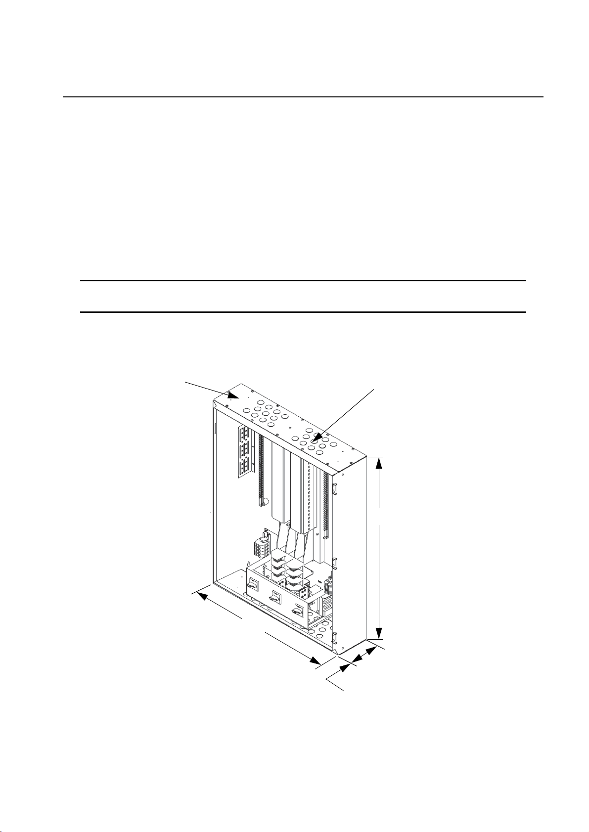
Product Overview
Top Plate Knockouts (22)
Space for Cutouts (both ends)
37.36 in
[949]
29.3 in
[750]
7.48 in
[190]
Features
The wall-mount version of the Smart-UPS VT and MGE Galaxy 3500 MBP combines bypass
functionality with power distribution capability in a common enclosure.The lower section of the MBP
contains switches that facilitate the transfer of power from the UPS to bypass operation to allow
maintenance to be performed on the UPS. The upper section houses a 42-position panel board for
distributing power to load.
The unit weighs approximately 120 lbs [54.5 kg]. The MBP can be installed quickly and easily to almost
any type of sturdy wall structure (refer to “Mounting the MBP” on page 9).
Product SKU Input Output
SBPSU10K30FC1M1-WP 81.3A, 208/120V, 3-Phase, 50/60Hz 83.3A, 208/120V, 3-Phase, 50/60Hz
The MBP enclosure supports both top and bottom cable entry. The unit contains three 90A fuses that
provide over-current and short-circuit protection.
3Smart-UPS® VT and MGE™ Galaxy™ 3500 10-30 kVA 208 V MBP Installation
Page 8
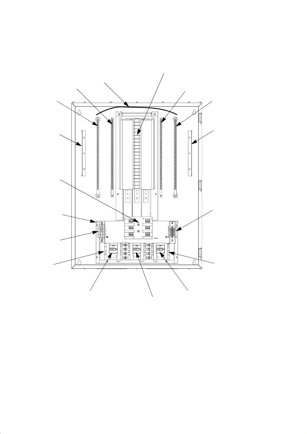
Internal components
Panel Board (42-position)
Neutral Bar
Neutral Bar
Ground Bar
Ground Bar
Strain-relief Bar
Strain-relief Bar
Fuse Block
([3]90A Fuses)
Power Terminal
Block
Control Terminal
Block
UPS Inputs
UPS Outputs
Q1 Switch
Q3 Switch
Q2 Switch
Neutral Bar
Cable Connection
Ground Terminal
Compression Lug
Smart-UPS® VT and MGE™ Galaxy™ 3500 10-30 kVA 208 V MBP Installation 4
Page 9

Schematic
5Smart-UPS® VT and MGE™ Galaxy™ 3500 10-30 kVA 208 V MBP Installation
Page 10

Considerations
18in [457mm]
36in [914 mm]
Environmental
• The wall area selected for the MBP installation must be structurally sound and able to
accommodate the size and weight of the unit. Refer to “Mounting the MBP” on page 9.
• The MBP should be kept in a climate-controlled environment having a temperature range of 0° to
40°C [32° to 104° F] and a relative humidity of 0% to 95%, non-condensing.
• The MBP must be protected at all times from excessive moisture, construction dirt, corrosive
S
elements, and other contaminants.
Smart-UPS® VT and MGE™ Galaxy™ 3500 10-30 kVA 208 V MBP Installation 6
Page 11

Installation
Overview
Warning: Review “Safety” on page 1 before starting this installation. Pay strict
attention to all safety warnings and caution notices!
• ALL INTERNAL cable connections were made prior to shipment.
• EXTERNAL cable connections with the UPS need to be made on-site. EXTERNAL cable
connections from the utility also need to be made on-site. EXTERNAL cable is not supplied.
• Control wire connections between the UPS and the MBP additionally need to be made on-site.
Control wires are not supplied.
• Panel board breakers must be ordered separately. Tie-wraps are not supplied.
Tools
The following tools are required for this installation:
• Dolly/hand-truck • M10 nut driver
• Tape measure • Standard (flathead)
• Pliers • Phillips screwdriver
• Level • T30 Torx screwdriver
• Marker • 4mm Allen wrench
• Drill • 1/2” socket with ratchet
Panel board breakers
The 42-position panel board supports the following Square D® 1-, 2-, and 3-pole bolt-on circuit
breakers. All of the circuit breakers listed below have been pre-tested and approved by APC.
Breaker Type APC Part# Breaker Type APC Part#
1-pole, 20Amp PD1P20ABBSD 3-pole, 20Amp PD3P20ABBSD
2-pole, 20Amp PD2P20ABBSD 3-pole, 80Amp PD3P80ABBSD
2-pole, 30Amp PD2P30ABBSD 3-pole, 100Amp PD3P100ABBSD
7Smart-UPS® VT and MGE™ Galaxy™ 3500 10-30 kVA 208 V MBP Installation
Page 12

Removing the front door (optional)
Front Door Locks (2)
Hinge Clips (3)
Hinges (3)
Rubber Plugs (3)
Note: Front door removal is NOT a requirement for this installation. However, removing the
door will allow better access to the internal components.
1. Place the MBP on its back such that its front door is facing straight up.
2. Use the enclosed keys to unlock and then open the front door.
3. Disconnect the internal ground cable from the ground stud on the door. Use an M10 nut driver to
remove the M6 flange nut securing the cable to the stud.
4. Using your thumb and forefinger, pull the three rubber plugs off the bottom ends of the three
hinge clips.
5. Using pliers, remove the three hinge clips connecting the door to the enclosure.
6. Remove the door. Store the door and all hardware in a safe location for later re-attachment.
Smart-UPS® VT and MGE™ Galaxy™ 3500 10-30 kVA 208 V MBP Installation 8
Page 13

Mounting the MBP
25.94 in [659]
33.86 in
Minimum 18 in [457] from floor!
[860]
1/4 x 1 in Lag Bolt (4)
1/4 in Flat Washer (4)
APC by Schneider Electric recommends mounting the MBP to 3/4 inches plywood backing (36 in
[914mm] high x 28 in [711mm] wide).
1. Attach the 3/4 inches plywood securely to the designated wall area. The wall should be strong
enough to support the 120lb [54.5kg] MBP. Leave at least 18in [457mm] of space between the
floor and the bottom of the plywood. Use appropriate hardware for the type of wall employed.
2. Measure and mark four (4) mounting-hole locations on the plywood backing. The locations will
be in the shape of a rectangle measuring 25.94in [659mm] across and 33.86in [860mm] down.
3. Drill starter holes in each of the four marked locations.
4. At least three people are needed to lift the MBP and position it against the plywood backing. Line
up the MBP’s four mounting holes with the four drilled starter holes.
5. Screw four (4) 1/4 x 1 inches hex-head lag bolts, along with four (4) 1/4 inches flat washers, into
the holes. Use a 1/2 inches socket with ratchet and tighten until rigid.
9Smart-UPS® VT and MGE™ Galaxy™ 3500 10-30 kVA 208 V MBP Installation
Page 14

Internal cable connections
Power Terminal Block
to Input Bus [L1, L2, L3, N]
Output Bus
to Input Fuse
Output Bus
to Neutral Bar [N]
Output Fuse Block
to Panel Board
Block [L1, L2, L3]
[L1, L2, L3]
For the convenience of the installer, ALL internal MBP cable connections were made prior to shipment.
Check to make certain the following internal cable connections were completed:
• Power Terminal Block [L1, L2, L3, N, top-to-bottom] to Input Bus [L1, L2, L3, N, top-tobottom]
• Output Bus [L1, L2, L3, top-to-bottom] to Input Fuse Block [L1, L2, L3, top-to-bottom]
• Output Bus [N] to Neutral Bar [N]
• Output Fuse Block [L1, L2, L3, top-to-bottom] to Panel Board [L1, L2, L3, left-to-right]
• Neutral Bar [N] to Neutral Bar [N] (refer to “Internal components” on page 4)
• Control Terminal Block to optional customer contacts [1, 2, 3, 4, 5, 6] and UPS connections for
Q3 [7, 8]. Note: The control wires from the UPS MUST
Auxiliary Contacts on Q3 [7, 8]. DO NOT
use terminals 5 and 6 for these connections! Refer to
be connected to the Normally Closed
“Schematic” on page 5 and to the appropriate wiring diagram in the UPS Installation Manual.
Smart-UPS® VT and MGE™ Galaxy™ 3500 10-30 kVA 208 V MBP Installation 10
Page 15

Making external cable connections
Utility to
Utility
G
Power Terminal Block
[L1, L2, L3, N]
to Ground [G]
Note: Utility cables can enter through the top or the bottom of the MBP. However, BOTTOM
is recommended.
External cables can enter the MBP through any of the available 1-inch [25.4mm] knockouts, or by
making larger cutouts in the top or bottom plates of the enclosure. Each plate offers 22 knockouts and the
ability to create up to four (4) 2-inch [50.8mm] cutouts.
Prior to making any of the following external cable connections, establish an appropriate point of access
by knocking out a 1-inch hole or cutting a larger hole in the top or bottom plate. The plate can be
removed using a Phillips screwdriver to loosen the 12 screws securing it to the enclosure. An M10 nut
driver is needed to remove the M6 flange nut securing the ground cable to the plate’s ground stud.
The cables are typically color coded: L1 = black, L2 = red, L3 = blue, N = white, and G = green.
Utility connections.
1. Connect the four inputs [L1, L2, L3, N, top-to-bottom] from the Utility to the Power Terminal
Block. Use a standard (flathead) screwdriver and torque to 60in-lbs [7Nm].
2. Connect the one ground input [G] from the Utility to the Ground Terminal Compression Lug.
Place the cable end in the bottom section of the compression lug, and then use a standard
(flathead) screwdriver and torque to 240in-lbs [27Nm].
11Smart-UPS® VT and MGE™ Galaxy™ 3500 10-30 kVA 208 V MBP Installation
Page 16

UPS connections.
UPS Inputs to Q1
UPS Outputs to
Control Wires [7, 8]
Switch [L1, L2, L3, N]
Q2 Switch [L1, L2, L3, N]
Note: UPS cables can enter through the top or the bottom of the MBP. However, BOTTOM is
recommended.
Refer to the Smart-UPS VT 10-30kVA or MGE Galaxy 3500, 208V Installation Manual for
MBP cable connections at the UPS.
1. Connect the four UPS inputs [L1, L2, L3, N, top-to-bottom] to the Q1 Switch in the MBP. Use a
4mm Allen wrench and torque to 60in-lbs [7Nm].
2. Connect the four UPS outputs [L1, L2, L3, N, top-to-bottom] to the Q2 Switch in the MBP. Use a
4mm Allen wrench and torque to 60in-lbs [7Nm].
3. Connect the two UPS control wires to Pins 7 and 8 in the MBP Control Terminal Block. Use a
standard (flathead) screwdriver and make the screws hand-tight.
Smart-UPS® VT and MGE™ Galaxy™ 3500 10-30 kVA 208 V MBP Installation 12
Page 17

Re-attaching the front door
Hinges (3)
Hinge Clips (3)
Rubber Plugs (3)
Note: This section applies only if the front door was removed at the start of the installation
process. If you chose not to remove the door, ignore this section.
Re-attaching the front door requires at least two people: one to hold the door in place, and the
other to make the necessary hardware connections.
1. Holding the door at an angle to the MBP enclosure, re-insert the three hinge clips into the three
door hinges.
2. Using your thumb and forefinger, push the three rubber plugs onto the bottom ends of the three
hinge clips.
3. Keeping the door open, re-connect the internal ground cable to the ground stud on the inside of
the door. Place the M6 flange nut over the cable lug on the stud. Use an M10 nut driver and
torque to 120in-lbs [14Nm].
4. Close and lock the front door.
13Smart-UPS® VT and MGE™ Galaxy™ 3500 10-30 kVA 208 V MBP Installation
Page 18

Installing Panel Board Breakers
3-pole Breaker
(positions
3-pole Breaker
(positions 2, 4, 6)
Bolt-on
Connections
1, 3, 5)
This section describes how to install breakers to the MBP’s 42-position panel board.
Electrical Hazard: Before installing breakers, make sure ALL MBP switches are in the
OFF position. From normal operation, first switch Q2 OFF, and then switch Q1 OFF.
1. Use the enclosed keys to unlock and open the front door of the MBP.
2. Select the next available breaker position(s) on the panel board, and then snap the new 1-, 2-, or
3-pole breaker into the appropriate guard rail.
Note: The panel board supports Square D
®
bolt-on circuit breakers. For a listing of
recommended breakers, refer to “Panel board breakers” on page 7.
The top pole of a 3-pole breaker must always be placed in an L1 position on the panel board.
Counting down from the top, these are positions 1, 7, 13, 19, etc. on the left side of the board
and positions 2, 8, 14, 20, etc. on the right side of the board.
1. Make the bolt-on connections (those nearer the center of the panel board). Use a standard
(flathead) screwdriver and torque to 24in-lbs [3Nm].
2. Remove the corresponding plastic blanking plate(s) located directly in front of the newly
installed breaker. The blanking plates can be accessed through the smaller, hinged “panel board”
door at the front of the MBP. Use one of the front door keys to open this door.
Note: After installation, panel board breakers can be accessed by simply opening the panel
board hinged door.
Smart-UPS® VT and MGE™ Galaxy™ 3500 10-30 kVA 208 V MBP Installation 14
Page 19

Appendix A: Changing Fuses
Fuse Puller
90A Fuse
Spring Clasps (top and bottom)
Metallic End (top and bottom)
Fuse Block
Warning: Before changing fuses, make sure ALL MBP switches are in the OFF
position. From normal operation, first switch Q2 OFF, and then switch Q1 OFF.
Note: Replace ALL blown fuses with Bussmann “Class J” 90 Amp fuses (p/n JKS-90).
Removing fuses
1. Open the front door of the MBP to access the fuse block. Use the enclosed front door keys.
2. Using a plastic or insulated fuse puller, tightly grasp the center section of the blown fuse.
3. Pull the fuse toward you, forcing its release from the two sets of spring clasps.
Replacing fuses
1. Using a plastic or insulated fuse puller, tightly grasp the center portion of the replacement fuse.
2. Align the fuse’s metallic ends with the two sets of spring clasps that will hold it in place.
3. Push the fuse into the two sets of clasps until the clasps snap around the metallic ends.
4. Close and lock the front door.
Note: After changing fuses, the MBP can be returned to normal operation by first switching
Q2 ON, and then switching Q1 ON. Q3 remains OFF.
15Smart-UPS® VT and MGE™ Galaxy™ 3500 10-30 kVA 208 V MBP Installation
Page 20

Page 21

Page 22

Page 23

Page 24

APC Worldwide Customer Support
Customer support for this or any other APC product is available at no charge in any of the following ways:
• Visit the APC Web site to access documents in the APC Knowledge Base and to submit customer
support requests.
– www.apc.com (Corporate Headquarters)
Connect to localized APC Web sites for specific countries, each of which provides customer support
information.
– www.apc.com/support/
Global support searching APC Knowledge Base and using e-support.
• Contact the
– Local, country-specific centers: go to www.apc.com/support/contact for contact information.
For information on how to obtain local customer support, contact the APC representative or other distributors
from whom you purchased your APC product.
APC Customer Support Center by telephone or e-mail.
Entire contents copyright 2009 American Power Conversion Corporation. All rights reserved. Reproduction
in whole or in part without permission is prohibited. APC, the APC logo, and TRADEMARK NAMES are
trademarks of American Power Conversion Corporation. All other trademarks, product names, and corporate
names are the property of their respective owners and are used for informational purposes only.
8/2009990-4198D-001
*990-4198D-001*
 Loading...