

Page 1

Supplemental Installation Information for
APC Chillers
This document contains reference information needed to connect APC equipment to APC chillers.
All water and electrical connections must be performed by a qualified contractor in
accordance with local and national codes.
Warn i n g
Model Cross Reference Information
APC MODEL NUMBER CARRIER MODEL NUMBER
ACCH050 30RAN015
ACCH084 30RAN025
ACCH120 30RAN035
ACCH167 30RAN050
Page 2
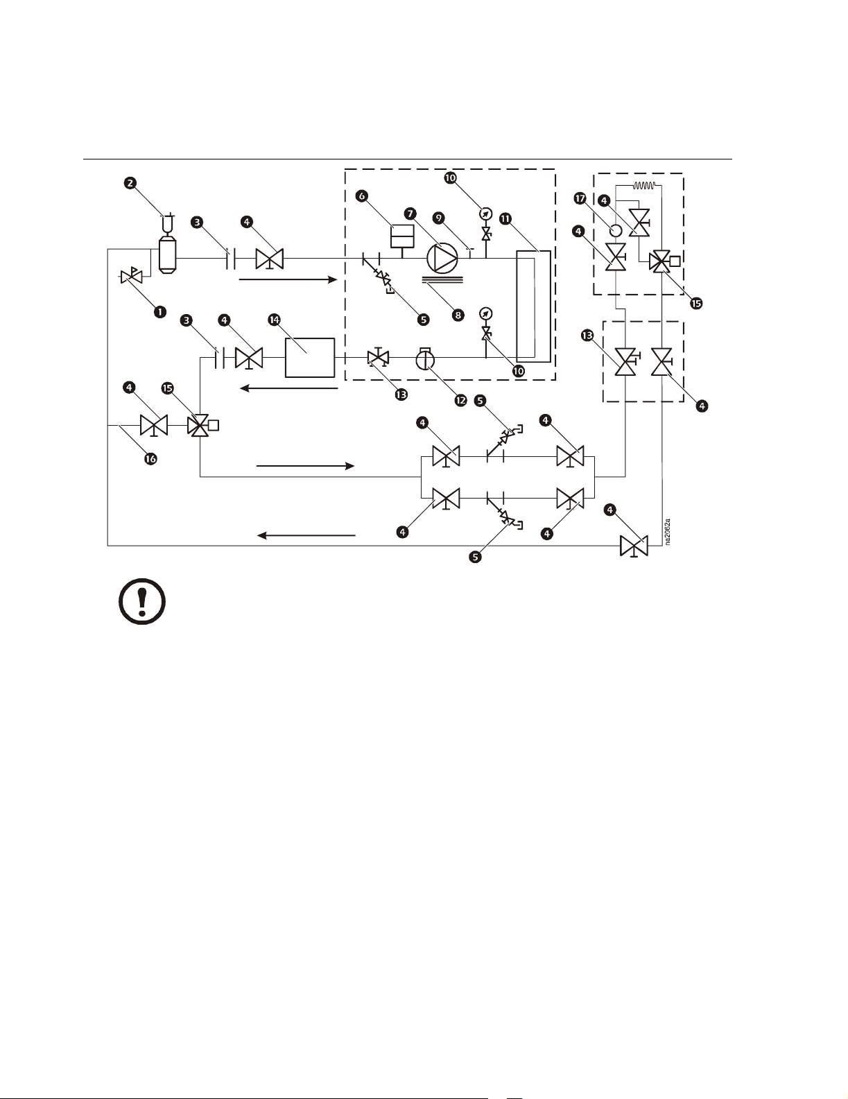
Typical Piping — Chiller to Cooling Distribution Unit (CDU)
CHILLER
RC
CDU
Note
Components inside dashed lines are included with the chiller, InfraStruXure InRow RC,
and CDU. All other items (valves, piping, etc.) are customer-supplied.
Pressure reducing/fill valve
Air separator and vent*
Flex connections
Isolation valves
Strainer/blow-down valve
Expansion tank
Dual pump
Electric heater
Air vent connection port
* Install at the highest point in the system.
**To provide the coldest possible water to the load, install the optional storage
tank on the leaving side of the chiller
Pressure gauges/petcocks
Heat exchanger
Flow switch
Balance valve/drain plug
Storage tank**
3-way valve
Bypass line
Flow meter
2 Supplemental Installation Information for APC Chillers
Page 3

Typical Piping — Single Chiller
CHILLER
CRACs
Note
Components inside dashed lines are included with the chiller and CRACs. All other items
(valves, piping, etc.) are customer-supplied.
Pressure reducing/fill valve
Air separator and vent*
Flex connections
Isolation valves
Strainer/blow-down valve
Expansion tank
Dual pump
* Install at the highest point in the system.
**To provide the coldest possible water to the load, install the optional storage
tank on the leaving side of the chiller
Electric heater
Air vent connection port
Pressure gauges/petcocks
Heat exchanger
Flow switch
Balance valve/drain plug
Storage tank — optional**
Supplemental Installation Information for APC Chillers 3
Page 4

Typical Piping — Redundant Chillers
CHILLER 1
Note
CHILLER 2
CRACs
Components inside dashed lines are included with the chillers and CRACs. All other
items (valves, piping, etc.) are customer-supplied.
Storage tank — optional*
Isolation valves
Flex connections
Check valves
Chilled water temperature sensor**
Strainer/blow-down valve
Pressure reducing/fill valve
Air separator and vent***
* To provide the coldest possible water to the load, install the optional storage
tank on the leaving side of the chiller
** Chilled water temperature sensor should be wired to both chillers.
*** Install at the highest point in the system.
**** When applied in redundant chillers, disconnect the expansion tank and install
a single expansion tank in the common header.
Expansion tank****
Heat exchanger
Pressure gauges/petcocks
Air vent connection port
Dual pump
Electric heater
Balance valve/drain plug
Flow switch
4 Supplemental Installation Information for APC Chillers
Page 5

Dual Power Feature (Optional)
The optional dual power feature provides a separate power connection point for the pumps and
controls. If the circuit is connected to an Uninterruptible Power Supply (UPS), the power connection
keeps the pumps running to recirculate cooling water in the event of a power failure.
Upon loss of power, all compressors and fans shut down. At the same time, the dual-power relay
closes, putting the unit in heat mode, allowing the controller to keep the pumps running and also
removes any call for cooling.
On power restoration, the dual power relay opens. The unit returns to cooling mode and stages up
compressors as required.
See the electrical schematics included in this packet containing electrical data on the power feeds for
the pumps and chiller.
Supplemental Installation Information for APC Chillers 5
Page 6

Power Requirements
APC Model
No
ACCH050GAKA-D03S
ACCH084GAKA-D03S
ACCH120GAKA-D05S
ACCH167GAKA-D05S
ACCH050GADA-D03S
ACCH084GADA-D03S
ACCH120GADA-D05S
ACCH167GADA-D05S
ACCH050GABA-D03S
ACCH084GABA-D03S
ACCH120GABA-D05S
ACCH167GABA-D05S
ACCH050GAAA-D03S
ACCH084GAAA-D03S
ACCH120GAAA-D05S
ACCH167GAAA-D05S
Main Power Supply
Dual Power Supply for Pumps and
Controls
Pump
LRA
Hz
PH
Volt s A C
460 3 60 506 414 37.3 60 33.3
460 3 60 506 414 54.0 70 50.9
460 3 60 506 414 79.5 100 75.5
460 3 60 506 414 101.8 110 98.7
460 3 60 506 414 33.6 50 29.6 460 3 60 506 414 15.0 15 5.7 28.5
460 3 60 506 414 50.3 70 47.2 460 3 60 506 414 15.0 15 5.7 28.5
460 3 60 506 414 73.2 90 69.2 460 3 60 506 414 15.0 15 8.3 65.0
460 3 60 506 414 95.5 110 92.4 460 3 60 506 414 15.0 15 8.3 65.0
208/
230
208/
230
208/
230
208/
230
208/
230
208/
230
208/
230
208/
230
3 60 253 187 77.5 125 69.3
3 60 253 187 110.6 150 104.4
3 60 253 187 167.3 200 159.1
3 60 253 187 208.6 225 198.3
3 60 253 187 69.3 110 59.1 208/230 3 60 253 187 15.0 15 10.2 60.0
3 60 253 187 102.4 125 94.2 208/230 3 60 253 187 15.0 15 10.2 60.0
3 60 253 187 153.4 200 143.2 208/230 3 60 253 187 17.4 30 15.9 138.8
3 60 253 187 194.6 225 186.4 208/230 3 60 253 187 17.4 30 15.9 138.8
Max Volts
MCA
Min Volts
FLA
MOCP
Volt s A C
PH
Hz
MCA
Min Volts
Max Volts
FLA
MOCP
6 Supplemental Installation Information for APC Chillers
Page 7

Page 8

APC Worldwide Customer Support
Customer support for this or any other APC product is available at no charge in any of the following
ways:
• Visit the APC Web site to access documents in the APC Knowledge Base and to submit
customer support requests.
– www.apc.com (Corporate Headquarters)
Connect to localized APC Web sites for specific countries, each of which provides customer
support information.
– www.apc.com/support/
Global support searching APC Knowledge Base and using e-support.
• Contact an APC Customer Support center by telephone or e-mail.
– Regional centers:
Direct InfraStruXure Customer Support Line (1) (877)537-0607 (toll free)
APC headquarters U.S., Canada (1)(800)800-4272 (toll free)
Latin America (1)(401) 789-5735 (USA)
Europe, Middle East, Africa (353)(91)702000 (Ireland)
Japan (0) 35434-2021
Australia, New Zealand, South Pacific area (61) (2) 9955 9366 (Australia)
– Local, country-specific centers: go to www.apc.com/support/contact for contact
information.
Contact the
information on how to obtain local customer support.
Entire contents copyright 2006 American Power Conversion Corporation. All rights reserved.
Reproduction in whole or in part without permission is prohibited. APC, the APC logo, and
InfraStruXure are trademarks of American Power Conversion Corporation. All other trademarks,
product names, and corporate names are the property of their respective owners and are used for
APC representative or other distributor from whom you purchased your APC product for
informational purposes only.
990-2921
990-2921 04/2006
*990-2921*
 Loading...