

A. O. Smith XB-1000 Service Manual
25589 Highway 1
McBee, SC 29101
Service Handbook
COMMERCIAL BOILERS
FOR MODELS: XB/XW
1000, 1300, 1700
2000, 2600, 3400
SERIES 100/101
INSTALLATION CONSIDERATIONS - PRE SERVICE CHECKS
- BOILER CONSTRUCTION -
OPERATION & SERVICE - TROUBLESHOOTING
SERVICING SHOULD ONLY BE PERFORMED BY A QUALIFIED SERVICE AGENT
PRINTED IN THE U.S.A. 0811 320822-001


TABLE OF CONTENTS
TABLE OF CONTENTS ..........................................................................3
INTRODUCTION .................................................................................... 4
Qualications ..................................................................................... 4
Service Warning ................................................................................ 4
Service Reminder .............................................................................. 4
Tools Required ................................................................................... 4
INSTALLATION CONSIDERATIONS ..................................................... 5
Instruction Manual ............................................................................. 5
Closed Water Systems ...................................................................... 5
Thermal Expansion ............................................................................ 5
Air Requirements ............................................................................... 5
Contaminated Air ............................................................................... 5
Venting ............................................................................................... 6
General Venting Information .............................................................. 6
Water Piping ...................................................................................... 6
Temperature Rise & Flow Rate .......................................................... 6
Boiler Controls ................................................................................... 7
Primary System Control ..................................................................... 7
Installation Checklist .......................................................................... 8
FEATURES AND COMPONENTS ......................................................... 9
OPERATION AND SERVICE ................................................................11
Modulating Fire Operation ................................................................11
Combustion Blower ..........................................................................11
Heat Exchanger Assembly .............................................................. 12
Venturi And Gas Train Assembly ..................................................... 14
Burner Assembly ............................................................................. 15
Flame Sensor .................................................................................. 17
Spark Igniter .................................................................................... 18
Gas Valve ........................................................................................19
Temperature Sensors ...................................................................... 20
Air Filter Assembly ........................................................................... 21
Control Panel Assembly .................................................................. 22
Control Board Assembly .................................................................. 25
Display System (Touch Screen Display) .......................................... 29
Connector Terminals ........................................................................ 29
BOILER START UP AND OPERATIONS ............................................. 31
Prior To Start Up .............................................................................. 31
General ............................................................................................ 31
Filling And Purging of Boiler Installation .......................................... 31
Filling Hot Water Supply Boiler Installation ...................................... 31
Inlet Gas Pressure ........................................................................... 31
Manifold Pressure Connections ....................................................... 32
Water Temperature Regulation ........................................................ 32
Check/Control Water Hardness ....................................................... 33
Freeze Protection (Hydronic Heating Installation) ........................... 33
Inspect/Fill Condensate System ...................................................... 33
LIGHTING AND OPERATING INSTRUCTIONS .................................. 34
Adjustment ....................................................................................... 35
Setting Of The Test Mode ................................................................ 35
CONTROL SYSTEM OPERATIONS .................................................... 38
Burner Control System .................................................................... 38
Overview .......................................................................................... 38
Burner Control Operation ................................................................ 40
General Operational Sequence ....................................................... 41
Lead Lag .......................................................................................... 42
Local operator interface: display system ......................................... 44
Installation Instructions (S7999B OI Display) .................................. 45
Page Navigation .............................................................................. 48
TROUBLESHOOTING ......................................................................... 58
Poor Combustion - Ignition Failure - Rough Start/Operation ........... 58
TROUBLESHOOTING CODES ............................................................ 60
PIPING DIAGRAMS ............................................................................. 75
3

INTRODUCTION
This Service Manual covers the boiler Model and Series numbers listed on the front cover only. The instructions and illustrations
contained in this manual will provide you with troubleshooting procedures to verify proper operation and diagnose and repair common
service problems.
QUALIFICATIONS
QUALIFIED INSTALLER OR SERVICE AGENCY
Installation and service of this boiler requires ability equivalent to that of a Qualied Agency (as dened by ANSI below) in the eld
involved. Installation skills such as plumbing, air supply, venting, gas supply and electrical supply are required in addition to electrical
testing skills when performing service.
ANSI Z223.1 2006 Sec. 3.3.83: “Qualied Agency” - “Any individual, rm, corporation or company that either in person or through
a representative is engaged in and is responsible for (a) the installation, testing or replacement of gas piping or (b) the connection,
installation, testing, repair or servicing of appliances and equipment; that is experienced in such work; that is familiar with all
precautions required; and that has complied with all the requirements of the authority having jurisdiction.”
If you are not qualied (as dened by ANSI above) and licensed or certied as required by the authority having jurisdiction to
perform a given task do not attempt to perform any of the procedures described in this Service Manual. If you do not understand the
instructions given in this manual do not attempt to perform any procedures outlined in this manual.
This product requires start-up certication by an qualied service agent that has been trained by the factory for this specic product.
Call 1-800-527-1953 to locate the nearest qualied service agency and arrange a factory certied start-up.
SERVICE WARNING
If you are not qualied (as dened by ANSI above) and licensed or certied as required by the authority having jurisdiction to perform
a given task do not attempt to perform any of the procedures described in this manual. If you do not understand the instructions given
in this manual do not attempt to perform any procedures outlined in this manual.
SERVICE REMINDER
When performing any troubleshooting step outlined in this manual always consider the wiring and connectors between components.
Perform a close visual inspection of all wiring and connectors to and from a given component before replacement. Ensure wires were
stripped before being crimped in a wire connector, ensure wires are crimped tightly in their connectors, ensure connection pins in
sockets and plugs are not damaged or worn, ensure plugs and sockets are mating properly and providing good contact.
Failure to perform this critical step or failing to perform this step thoroughly often results in needless down time, unnecessary parts
replacement, and customer dissatisfaction.
TOOLS REQUIRED
• Instruction Manual that came with the boiler.
• All hand tools common to installation and service of commercial water heaters and boilers such as torch, pipe wrenches etc.
• TORX® T40 or 5 mm hex wrench - for setting gas mixture at gas valve.
• 3 mm or 7/64 inch hex (Allen) wrench - for setting gas mixture at gas valve.
• 6 mm allen key, Long (8-10”) T handle 1/8 inch hex (allen key) wrench for Blower removal and installation.
• Hex (Allen) wrench sizes: 1/2”, 5/32”, 1/8”, 1/4” and 5/16" or TORX® T25/T40 - for Burner, and 24V Gas Valve removal and
installation.
• Two Manometers or Pressure Gauges.
• One - U tube manometer or gauge for measuring supply gas pressure.
• One (optionally two) digital Manometer(s) range -20.00 to +20.00" W.C., resolution 0.01" W.C. Recommend UEI model
EM200, TPI model 620 or equivalent. Used to measure manifold gas pressures and to test performance of pressure
switches. Optional second digital manometer can be used in place of U tube manometer for measuring supply gas
pressures.
• True RMS Digital Multi Meter DMM, recommend UEI model DL289 or Fluke equivalent. Capable of measuring:
• AC/DC Voltage.
• Ohms.
• DC micro amps (μA) - ame sensing current.
• AC amp meter- recommend UEI model DL289 or equivalent.
• Combustion analyzer capable of measuring:
• CO2 (carbon dioxide).
• CO (carbon monoxide).
• Draft Pressure.
• Exhaust Temperature (vent gases).
4
Servicing should only be performed by a Qualied Service Agent

INSTALLATION CONSIDERATIONS
This section of the Service Manual covers some of the critical installation requirements that, when overlooked, often result in
operational problems, down time and needless parts replacement. Costs to correct installation errors are not covered under the
limited warranty. Ensure all installation requirements and instructions contained in the Instruction Manual that came with the boiler
have been followed prior to performing any service procedures.
INSTRUCTION MANUAL
Have a copy of the Instruction Manual that came with the boiler on hand for the model and series number being serviced. Installation
information given in this Service Manual is not a complete installation instruction. Installation information given in this manual has
a limited focus as it applies to servicing the boiler. This Service Manual does not replace or supersede the Instruction Manual that
came with the boiler. Always refer to the Instruction Manual for complete installation instructions. If the Instruction Manual is not on
hand copies can be obtained from the manufacturers web site or by calling the technical support phone number shown on the back
cover of this manual.
CLOSED WATER SYSTEMS
Water supply systems may, because of code requirements or such conditions as high line pressure, among others, have installed
devices such as pressure reducing valves, check valves, and back ow preventers. Devices such as these cause the water system
to be a closed system.
THERMAL EXPANSION
As water is heated, it expands (thermal expansion). In a closed system the volume of water will grow when it is heated. As the
volume of water grows there will be a corresponding increase in water pressure due to thermal expansion. This type of failure is not
covered under the limited warranty. Thermal expansion can also cause intermittent Temperature-Pressure Relief Valve operation:
water discharged from the valve due to excessive pressure build up. This condition is not covered under the limited warranty. The
Temperature-Pressure Relief Valve is not intended for the constant relief of thermal expansion.
A properly sized thermal expansion tank must be installed on all closed systems to control the harmful effects of thermal expansion.
Contact a local plumbing service agency to have a thermal expansion tank installed.
AIR REQUIREMENTS
Carefully review the requirements for combustion and ventilation air in the Instruction Manual that came with the boiler. Failure
to meet these requirements when the boiler is installed or overlooking their importance when servicing the boiler often results in
needless down time, unnecessary parts replacement, and customer dissatisfaction.
An inadequate supply of air for combustion and ventilation often causes operational problems. A lack of combustion and ventilation air
can create a negative ambient air pressure in the installed space which can lead to improper combustion and operational problems.
CONTAMINATED AIR
Combustion air that is contaminated can greatly diminish the life span of the boiler and boiler components such as Igniters and
Burners. Propellants of aerosol sprays, beauty shop supplies, water softener chemicals and chemicals used in dry cleaning processes
that are present in the combustion, ventilation or ambient air can cause such damage.
Vapors from volatile compounds such as solvents, cleaners, chlorine based chemicals and refrigerants in addition to being highly
ammable in many cases, can also react to form highly corrosive substances such as hydrochloric acid inside the combustion
chamber. The results can be hazardous and cause product failure.
If the boiler is installed in beauty shops, barber shops or laundries with dry cleaning equipment, it is imperative the boiler be installed
in a Direct Vent conguration so that air for combustion is derived directly from the outdoor atmosphere through a sealed intake
air pipe. See the venting installation section in the Instruction Manual that came with the boiler for more information on Direct Vent
installations.
Servicing should only be performed by a Qualied Service Agent
5

VENTING
This section of the Service Manual is not a complete venting installation instruction. Refer to the Instruction Manual that came with
the boiler; ensure the venting has been installed per all Instruction Manual requirements. Failing to install the factory provided vent
and/or intake air terminations, exceeding the maximum equivalent vent and/or intake air piping lengths, adding too many elbows to
the intake air and/or vent pipes, installing the wrong vent intake air pipe size, will cause operational problems, improper combustion,
rough starting/operation and Control System lock out costs to correct installation errors are not covered under the limited warranty.
GENERAL VENTING INFORMATION
The boilers covered in this manual are operationally equivalent to Category IV appliances and may be installed in either a Power
Vent or Direct Vent conguration.
Category IV Appliance
Category IV appliances operate with a positive vent (exhaust) static pressure and with vent gas temperatures low enough to produce
condensate in the vent piping.
Power Vent Conguration
Power Vent congurations derive all combustion air from the room where they are installed and discharge all ue gases to the outdoor
atmosphere through a sealed vent (exhaust) pipe. Power vent congurations have one vent pipe connected to the boiler which can
be terminated in a vertical or horizontal arrangement.
Direct Vent Conguration
Direct Vent congurations derive all combustion air directly from the outdoor atmosphere through a sealed intake air pipe and
discharge all ue gases to the outdoor atmosphere through a sealed vent (exhaust) pipe. Direct Vent congurations have two pipes
connected to the boiler, one vent pipe and one intake air pipe. Direct Vent congurations can also be terminated in a vertical or
horizontal arrangement.
WATER PIPING
Ensure all water piping requirements, diagrams and piping installation instructions contained in the Instruction Manual that came with
the Boiler have been observed and followed. Factory installed pumps on XP Boilers are sized for up to a maximum of 25 equivalent
feet of outlet (supply) and inlet (return) piping; 50 equivalent feet total. Exceeding these limitations will lead to Control System lock
outs and can permanently damage the boiler's heat exchangers. A bypass line must be installed between the outlet and inlet piping
of the boiler on the "system side" of the boiler's circulation pump to prevent condensation on the copper heat exchanger.
TEMPERATURE RISE & FLOW RATE
Water ow rates through the boiler are critical. Flow rates that are too low may cause excessive lime/calcium accumulation inside the
heat exchanger; while ow rates that are too high can lead to velocity erosion that can eventually cause water leaks. Boiler efciency
is also affected by ow rates. Measuring the actual water ow rate (gallons per minute) through the boiler is often impractical in the
eld. Because the temperature rise through the boiler is directly linked to the ow rate and is simple to measure, temperature rise is
commonly used to conrm proper ow rates.
Temperature rise is calculated by subtracting the inlet water temperature from the outlet water temperature. Temperature rise is
commonly referred to as the "Delta T" and expressed as ΔT. The temperature rise through the boiler should be set between 20° F
and 30° F. Temperature rise (ow rate) is set by throttling a ow control valve installed in the boiler's outlet (supply) water line with
the boiler ring at 100%. Never attempt to throttle the outlet valve unless the boiler is ring at 100%. Valves on the boiler's inlet
(return) water line must never be throttled and left fully open at all times except when servicing the boiler. The outlet temperature,
inlet temperature are shwon on the display system. Delta T (ΔT) must be below 75° F. If this is exceeded, the display will show an
alert and the individual burner will lock out.
6
Servicing should only be performed by a Qualied Service Agent
BOILER CONTROLS
Boiler controls that are improperly installed or congured can cause serious operational and service related problems such as short
cycling. This section provides information for how various controls can work together or independently to provide proper boiler and
system control.
PRIMARY SYSTEM CONTROL
All XP boiler installations require a “Primary System Control” that senses and reacts to water temperature inside the storage tank on
domestic water applications or in the return line on primary/secondary hydronic heating systems. The Primary System Control will
activate and deactivate boiler heating cycles based on its setpoint and current system water temperature. There are three suitable
methods to congure a Primary System Control. One of these three methods must be used.
1. The Primary System Control can be the boiler’s control system working with the factory supplied Header Sensor, installed inside
the storage tank on domestic water applications or in the return line on primary/secondary hydronic heating systems.
2. Alternatively, the Burner Control system can be used as a Primary System Control. It will also provide boiler status and error
reporting. Multiple boilers can be joined together to heat a system instead of a single, larger burner or boiler. Using boilers in
parallel is more efcient, costs less, reduces emissions, improves load control, and is more exible than the traditional large
boiler.
3. MB2 and COM2 ports can be used for Building Management Systems.
FIELD WIRING
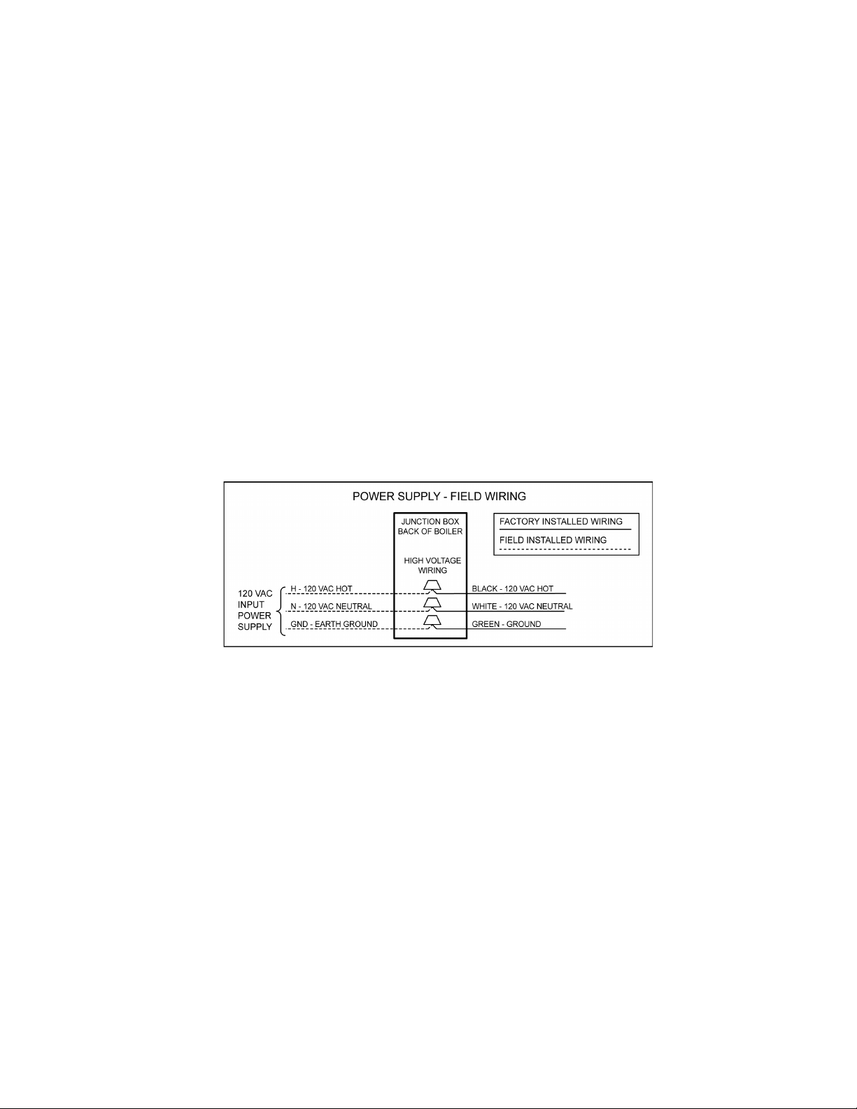
120 VAC Power Supply Wiring
A dedicated, single phase, 30/60 amp circuit breaker with a grounded neutral should be provided to supply power to the boiler(s). Use
#10 AWG wire for the 120 VAC power supply to the boiler. All 120 VAC power supply connections must be made as shown in Figure
1. These connections should be made at the rear of the boiler where a wiring junction box is provided. Field installed power supply
wiring to the boiler should be installed in conduit. This conduit and wiring should be separate from any other conduit/wiring to guard
against EMI (electromagnetic interference).
FIGURE 1. FIELD WIRING
Power Supply Check
To reduce the possibility of electrical interference with the boiler’s control system, the power supply voltage, polarity and ground
must be checked. Using an AC volt meter check the 120 VAC power supply wiring from the breaker prior to making power supply
connections at the boiler. Conrm the power supply voltage & polarity are correct and that an adequate ground connection is present
by performing the three voltage tests below. See Figure 1.
Conrm RMS voltage between:
• H and GND = 108 VAC minimum, 132 VAC maximum.
• N and H = 108 VAC minimum, 132 VAC maximum.
• N and GND = < 1 VAC maximum.
Servicing should only be performed by a Qualied Service Agent
7

INSTALLATION CHECKLIST
The list below represents some of the most critical installation requirements that, when overlooked, often result in operational
problems, down time and needless parts replacement. Before performing any troubleshooting procedures use the list below to
check for installation errors. Costs to correct installation errors are not covered under the limited warranty. Ensure all installation
requirements and instructions contained in the Instruction Manual that came with the boiler have been observed and followed.
1. The vent (exhaust) pipe must not be combined or connected to any other appliance’s vent system or chimney.
2. The intake air pipe must not be combined or connected to any other appliance’s intake air piping.
3. The boiler(s) covered in this manual are condensing appliances. Condensate will form in the vent pipe during normal operation,
condensate can also form in the intake air piping in certain circumstances. Ensure the intake air and/or vent piping is not installed
in a manner that will allow water to be trapped in the piping. This will lead to blocked exhaust and/or blocked air intake fault
conditions and Control System lock outs.
4. Ensure the intake air and/or vent piping is the correct size for the installed length. See the venting requirements section in the
Instruction Manual that came with the boiler. Using smaller pipe than is required will lead to blocked exhaust and/or blocked air
intake fault conditions and Control System lock outs.
5. Ensure the intake air and/or vent piping are within the maximum equivalent lengths required in the Instruction Manual that came
with the boiler. Exceeding the maximum length or number of elbows allowed will also lead to blocked exhaust and/or blocked air
intake fault conditions and Control System lock outs.
6. Ensure there is a water trap formed in the condensate drain tube/line connected to the exhaust elbow on the boiler and that the
condensate drain is owing freely. Condensate drain blockage will cause the heat exchanger to ll with water and lead to blocked
exhaust fault conditions and Control System lock outs.
7. Ensure the vent and intake air terminations have adequate clearances from each other and the terminations of other appliances.
Failure to maintain adequate clearances can cause the recirculation of ue gases between the vent and intake air piping.
Recirculation of ue gases will cause poor combustion, sooting, ignition failure, rough starts, rough operation, premature failure
of the heat exchanger and icing of the combustion air intake during severe cold weather.
8. Direct vent terminations being installed in dead air spaces such as alleys, atriums, and inside corners can also cause the
recirculation of ue gases between the vent and intake air piping. To prevent the recirculation of ue gases, maintain as much
distance as possible between the intake air and vent terminations.
9. Ensure the screens in the factory supplied terminations are securely installed to prevent blockage in the intake air and/or vent
piping.
10. On Direct Vent installations ensure the screen at the intake air connection on the water heater was removed before the intake air
piping was connected.
11. Ensure the power supply connections to the water heater are polarity correct. Use the Digital Multi Meter to verify correct polarity
and ground at an outlet the water heater is plugged into. Reversed polarity (neutral and hot wires reversed) will cause the AC
Reversed fault condition and Control System lock out.
12. Ensure the boiler and the burner are properly grounded. The boiler Control System requires an adequate earth ground for ame
sensing (verication). Inadequate grounding to the water heater and/or the burner will cause the Ignition Failure fault condition
and Control System lock out.
8
Servicing should only be performed by a Qualied Service Agent
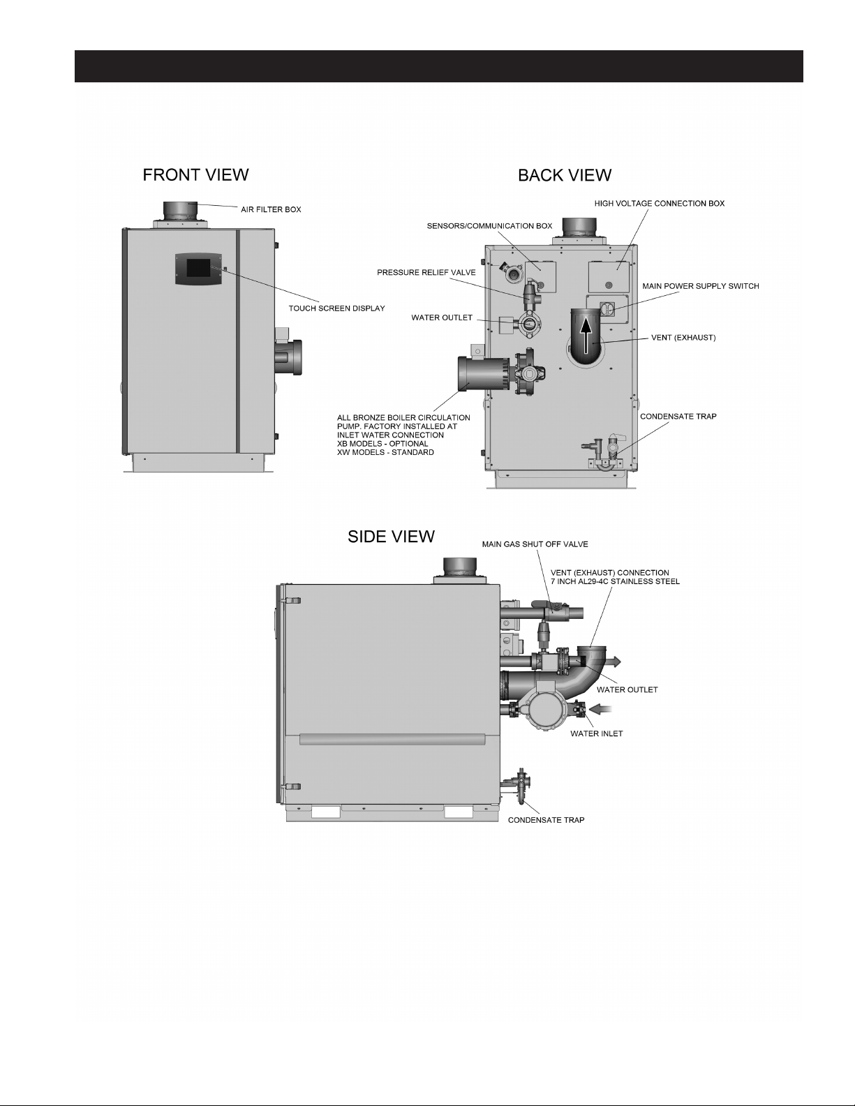
FEATURES AND COMPONENTS
FIGURE 2. SINGLE HEAT EXCHANGER BOILER - 1000/1300/1700
Servicing should only be performed by a Qualied Service Agent
9
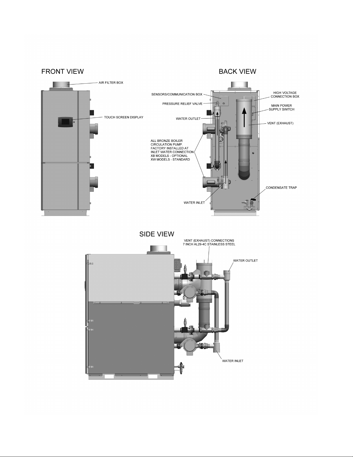
FIGURE 3. DOUBLE HEAT EXCHANGER BOILER - 2000/2600/3400
10
Servicing should only be performed by a Qualied Service Agent
OPERATION AND SERVICE
MODULATING FIRE OPERATION
XP Boilers are modulating re boilers. The control system modulates the ring rate of the burner to match system load by controlling
the speed of the combustion blower.
XP Boilers do not have a gas orice. The combustion blower "pulls" fuel gas from the outlet of the 24 VAC gas valve (when energized)
into a venturi that is connected to the inlet of the Combustion Blower. The ring rate of the boiler is directly proportional to the speed of
the combustion blower motor. As the blower speed increases, the pressure inside the venturi falls creating a stronger vacuum which
pulls more fuel gas into the blower/burner assembly which increases the ring rate.
The control system controls the speed of the combustion blower in response to system temperature. As the system temperature falls
blower speed is increased to provide more heating capacity. The control system sends digital speed instructions to the electronic
speed control which is part of the combustion blower assembly.
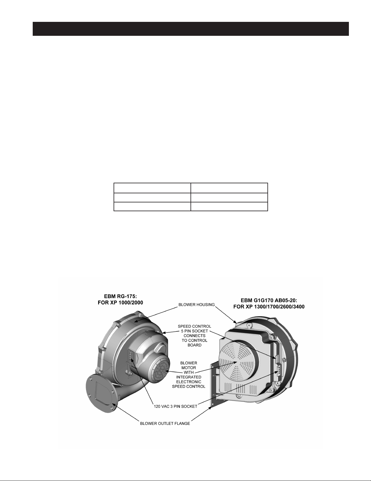
COMBUSTION BLOWER
The combustion blower is an assembly that includes the blower motor, housing and an integral electronic speed control. The power
junction box sends 120 VAC and an earth ground from its J3 socket to the 120 VAC 3 pin socket on the combustion blower assembly
to power the electronic speed control. The control board sends a PWM (Pulse Width Modulation) signal, an instruction to start, stop
and control the blower motor speed from the J2 socket to the 5 pin wiring socket on the combustion blower assembly. Four wires from
the J2 socket on the control board carry this instruction to the 5 pin wiring socket on the combustion blower assembly, see Figure 4
below.
TABLE 1. COMBUSTION BLOWERS
XP (XB/XW) MODELS BLOWER PART NUMBERS
1000/2000 EBM RG-175
1300/1700/2600/3400 EBM G1G170-AB05-20
Service Note:
The 5 pin PWM signal plug must remain plugged in to the 5 pin socket on the blower assembly at all times. Disconnecting this plug
will cause the combustion blower to run at maximum speed continuously. This may cause rough starts, rough operation and control
system lock out. If the electronic speed control is functioning properly combustion blower speed should noticeably reduce during the
operating state. If blower speed reduction does not occur during the operating state ensure the 5 pin plug from the control board is
securely plugged into the matching 5 pin socket on the blower assembly and that the J2 plug is securely plugged into the J2 socket
on the control board. Perform a close visual inspection of the pins inside the plugs and sockets at the combustion blower and the
control board, replace any worn or damaged wiring harnesses as necessary.
FIGURE 4. COMBUSTION BLOWER ASSEMBLY
Servicing should only be performed by a Qualied Service Agent
11
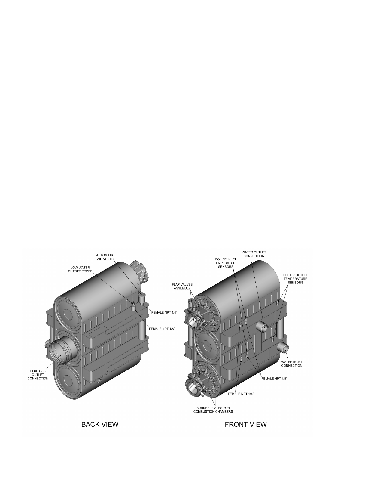
HEAT EXCHANGER ASSEMBLY
The heat exchanger transfers heat from the hot ue gases to the heating system’s water. Combustion products including ue gas
condensate, which are formed in the heat exchanger from 2nd and 3rd gas family are evacuated. The heat exchanger includes the
following interfaces:
• 2x Burner doors
• Flue gas outlet connection
• Water inlet and outlet connection
• Condensate connection
• Bushes for sensor
Heat from the hot ue gases is transferred to the heating water through a spiral tube made from stainless steel. The heat exchanger
is equipped with an evacuation for the combustion products at the back side. The burner doors should integrate a double tightness:
a gasket insuring a thermal protection and a gasket tight to the condensates and ue gas. The burner door should be in contact with
the front panel of the heat exchanger in order to limit the risk of leakage from combustion products in case the gaskets are incorrectly
reinstalled. Bolts on the front of the boiler can withstand forces resulting from the weight of the front panel and assembled parts
(burner door, fan, gas valve, venturi, air-gas sleeve). Maximum nuts torque for assembling the burner door is 3.7 ft.lb.
Minimum working pressure rated capacity is 14.5 PSI and the minimum water volume is 1.1 GPM per tube. Under these conditions
the maximum temperature difference between the outgoing and returning water is 80°F. With a Maximum Allowable Working Pressure
of 160 PSI, the exchanger’s hot water circuit system does not tolerate long-lasting leaks or deformations. Minimum water pressure for
a closed-loop system must not be lower than 14.5 PSI. Normal Heating circuit water temperature is 41°F – 203°F .
The ambient temperature around the product must not exceed 140°F and the ambient relative humidity (RH) can vary from 0% to a
maximum of 90%. In the extreme case of a safety component malfunctioning and causing the system to overheat to a temperature
higher than 203°F (closed system), the water temperature shall not exceed 210°F referring to the ASME Code Section IV for austenitic
stainless steel materials. The maximum surface temperatures for the casing, back panel and front panel must not exceed 302°F.
The Trio ASME “H” Heat Exchangers are equipped with 2 water male connections with NPT threading, according to the ANSI/ASME
B1.20.1 standard, which are dimensioned according to the capacity of the heat exchanger. A female NPT 1/8” threaded connection
type, according to the ANSI/ASME B1.20.1 standard, is available on the water ow and on the water return header of each stage
in order to receive some NTC sensors able to control the water ow and return temperature and/or to use its as a limiter and safety
thermostat. A female NPT 3/4" threaded connection type, according to the ANSI/ASME B1.20.1 standard, could be available on
the header in order to set an ASME certied pressure relief valve dimensioned according to the capacity of the heat exchanger.
Otherwise, the customer could t the pressure relief valve on the water pipe connected to the water header.
12
FIGURE 5. HEAT EXCHANGER ASSEMBLY
Servicing should only be performed by a Qualied Service Agent

Water Connection
Heat Exchangers are equipped with 2 water male connections with NPT threading, according to the ANSI/ASME B1.20.1 standard,
which are sized according to the capacity of the heat exchanger.
Flue Gas Outlet Connection
The heat exchanger is equipped with an evacuation for the combustion products at the back side. Flue gas outlets are dimensioned
according to the capacity of the heat exchanger.
A. o. Smith recommends the recovery and the evacuation of the ows coming from the chimney, mainly if there’s a risk of remains in
the chimney’s channel, in order to avoid that they return in the heat exchanger.
Burner Door/Plates Connection
A. O. Smith recommends that the burner doors should integrate a double tightness, a gasket insuring a thermal protection and a
gasket tight to the condensates and ue gas.
A. O. Smith recommends as well that the burner door should be itself in contact with the front panel of the heat exchanger in order to
limit the risk of leakage from combustion products in case of lack of remounting the gaskets.
Bolts on the front of the boiler can withstand forces resulting from the weight of the front panel and assembled parts (burner door, fan,
gas valve, venturi, air-gas sleeve). Maximum nuts torque for assembling the burner door is 3.7 ft.lb.
Operating Conditions - Installation factors
Heating units will be subject to the effects of corrosion from the moment they are lled with water. It is however essential that the
following installation factors are taken into account in order not to worsen the phenomenon of corrosion.
• Combustion air must not contain chlorine, ammonia, or alkali agents. Installation of a boiler near a swimming pool, a washing
machine, or a laundry do expose combustion air to these contents.
• The heat exchanger must be used lled with water within the temperature and pressure limits specied in its technical specication
booklet.
• The water's pH must fall within the following limits: 7.5<pH<9.5 and if the system contains aluminium parts, it must be less
than 8.5. This pH value is achievable after steady state conditions after lling the mains network water (pH around 7) inside the
installation and the air bleeding operation has been done ( death water condition).
• Water hardness must fall within the following limits:
• 5°F<TH<15°F
• 3 Grains/US gallon<TH<9 Grains/US gallon
• To avoid to the maximum presence of oxygen in the system, it is advised to prevent as much as possible air intake and water
leakage during installation. Usual spots where air is most likely to seep in are: suction gasket, pump, air valve working as venting
pipe, O-rings gaskets in stufng box. Using an automatic water rell system reduces some risk (as any fresh water is bringing
fresh oxygen in the system), like installing a water meter so that it is possible to evaluate the water volume in order to eliminate
any water leakage as early as possible.
• A minimum water pressure, adapted to each exchanger type, is requested in order to allow good performances.
• A. O. Smith recommends to the customers to carry out the drain of the heat exchanger after test or use in order to avoid
consequences on the product in the event of freezing ; the expansion of the water in case of freezing could cause degradations
or leakages.
Servicing should only be performed by a Qualied Service Agent
13
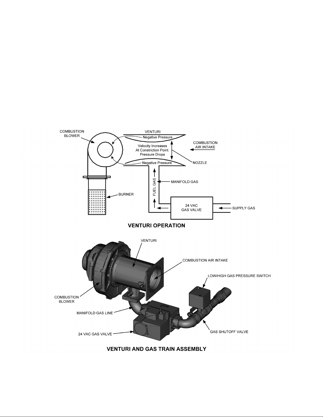
VENTURI AND GAS TRAIN ASSEMBLY
The gas train includes a venturi connected to the inlet of the combustion blower. The outlet of the 24 VAC gas valve is also connected
to the venturi by a manifold gas line. There is a shutoff valve installed in the manifold gas line for start up and service procedures. The
venturi contains a convergent/divergent nozzle (cone shaped restrictor) that constricts the air passage to the blower. As air enters the
constriction point its velocity increases. A pressure drop occurs at this point and creates a negative (vacuum) pressure in the cavity
between the nozzle and the venturi housing. This negative pressure “pulls” gas from the outlet of the 24 VAC gas valve into the blower
where it is mixed with combustion air and then supplied to the burner, see Figure 6.
As the combustion blower speed is increased the velocity of air owing through the venturi is also increased. This increases the
vacuum created by the venturi and more fuel gas is pulled from the 24 VAC gas valve and supplied to the burner. This increases the
ring rate (input Btu/hr) of the XP Boiler. As the blower speed is decreased less fuel gas is supplied to the burner and the ring rate
is reduced.
14
FIGURE 6. VENTURI AND GAS TRAIN ASSEMBLY
Servicing should only be performed by a Qualied Service Agent
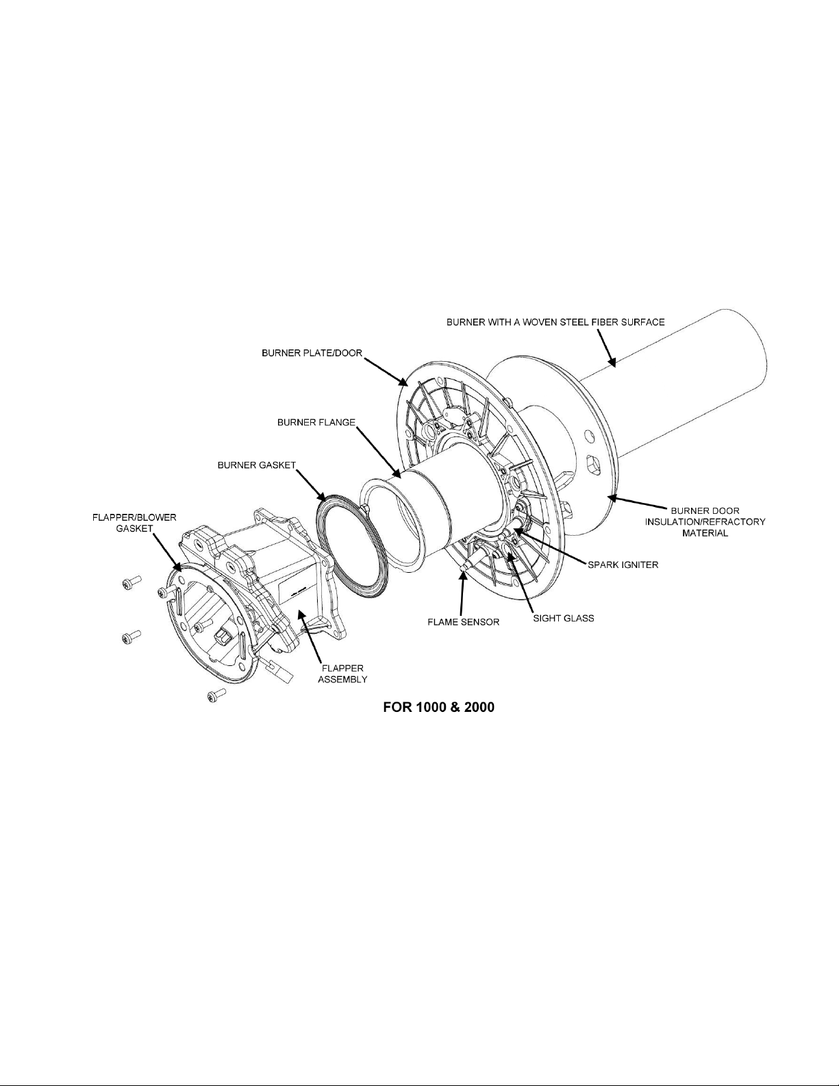
BURNER ASSEMBLY
The burner on the XP Boiler is a stainless steel radial re burner with a woven steel ber surface. It is installed in the center of the
horizontal heat exchanger. The burner is mounted inside the recess of the heat exchanger.
The spark igniter on the XP Boiler is a 120VAC igniter. The igniter receives power from the J5 socket on the Control Board. Normal
resistance of the igniter is 40-70 ohms @ 77°F (25°C). The control system monitors current through the igniter and must sense a
minimum of 0.5-1volts before it will energize the 24VAC gas valve.
A Low/High Gas Pressure Switch is installed on the gas manifold. The Low Pressure Gas Switch is a normally open switch that closes
on a rise in pressure. Switch contacts closes in between +4" W.C.(minimum) - +14" W.C.(maximum) on natural gas models and +8"
W.C.(minimum) - +14" W.C.(maximum) on propane gas models. The High Gas Pressure Switch is normally closed and is used to
detect excessive gas pressure.
XP Boilers have only one ame sensors. The ame sensor is mounted close to the burner to sense the ame ring rates.
FIGURE 7. BURNER ASSEMBLY (1000/2000)
Servicing should only be performed by a Qualied Service Agent
15
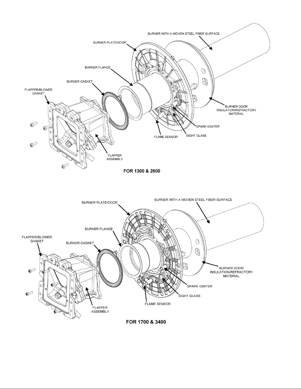
FIGURE 8. BURNER ASSEMBLY (1300/2600)
16
FIGURE 9. BURNER ASSEMBLY (1700/3400)
Servicing should only be performed by a Qualied Service Agent
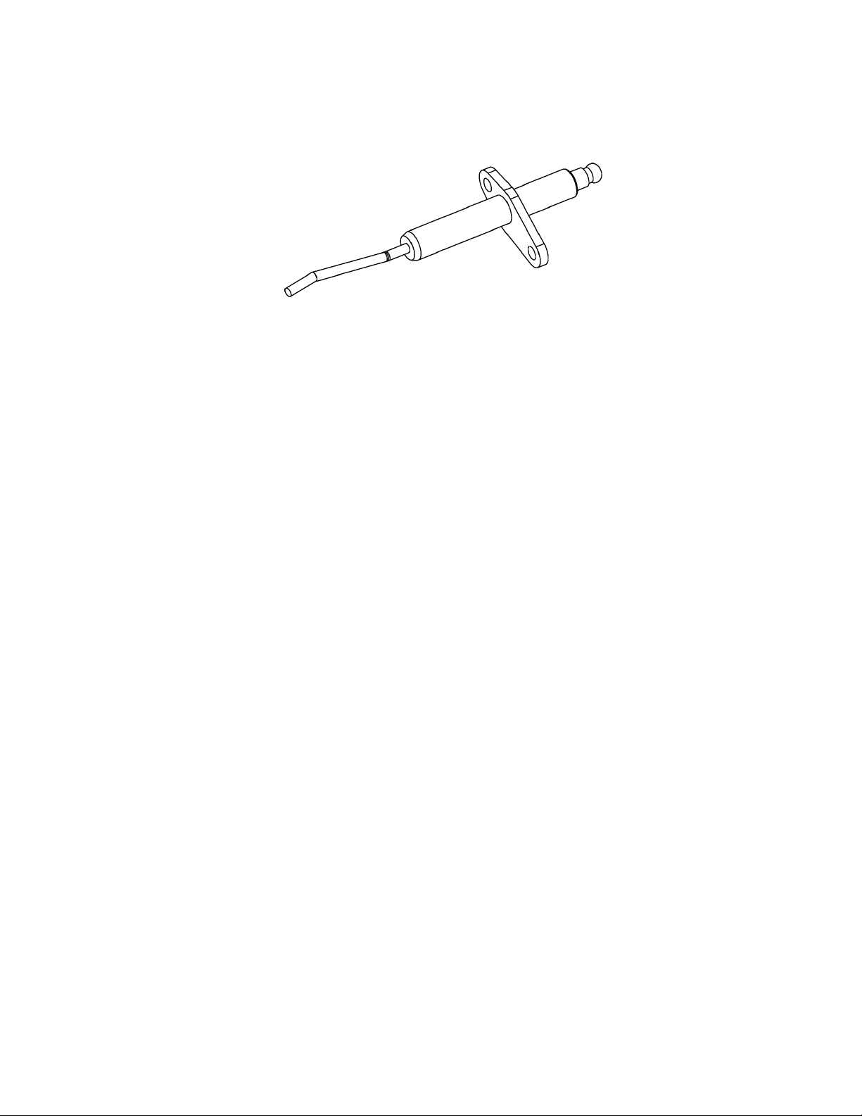
FLAME SENSOR
Ignition of the burner is controlled electronically. The principle of operation for electronic ignition relies on ame sensing voltage to
prove the fuel gas owing to the burner has been ignited and is burning safely.
Flame sensing requires correct power supply polarity and an adequate earth ground to the boiler's burner. See Figure 7 on Page 15,
Figure 8 and Figure 9 on Page 16 for the Burner Assembly.
FIGURE 10. FLAME SENSOR
Flame Sensing Operation
• The Flame Sensor is a metal (conductor) rod mounted in a ceramic insulator.
• The Control System applies an AC voltage to the Flame Sensor through a single wire.
• The burner ame will conduct a small amount of electrical current.
• The Burner must be grounded for current to ow from the Flame Sensor to the Burner.
• During ignition the burner ame must make complete and continuous contact with the Flame Sensor.
• As the AC voltage ows from the Flame Sensor through the burner ame to the (grounded) Burner, the AC voltage is "rectied"
and becomes a DC voltage.
• The current owing between the Flame Sensor and Burner is DC micro amp current expressed as: μA. Flame sensing voltage
can be measured with a Digital Multi Meter. See Tools Required on Page 4.
Flame Signal Processing
The ame signal processing will monitor the ame sensor. The ame signal voltage at the test jacks or on the bar graph on the display
is the measured voltage in the range from 0V to 15V. The display could show stronger numerical data.
The incoming ame signals are ltered to eliminate transient and spurious events. The ame failure response time (FFRT) is 4
seconds. Flame sensitivity is set by the Flame Threshold parameter, which will provide the ON/OFF threshold specied in volts or
microamps (1 volt is equivalent to 1 microamp)..
Service Notes:
• Ensure you have identied the correct Flame Sensor wire before performing a ame sensing test to prevent damage to the test
meter.
• The most common cause of ignition failure is a corroded Flame Sensor. Rust/corrosion will accumulate on the Flame Sensor
over time. The Flame Sensor should be inspected and cleaned anytime the measured ame sensing voltaget is at a minimum
of 1 volt or the Burner has been removed. Clean the Flame Sensor with ultra ne steel wool. DO NOT use a coarse abrasive
material such as sand paper for cleaning. Inspect the ceramic insulator on the Flame Sensor for cracks, replace the Flame
Sensor if it is damaged. The Combustion Blower and Burner must be removed to access the Flame Sensor.
• An open ame sensing circuit caused by disconnected or loose connectors can also cause ignition failure. Check all wiring
connections between the Flame Sensor and the J1 connector on Control Board.
• The burner not being grounded will cause ignition failure. Ensure the boiler and the burner are properly grounded.
Servicing should only be performed by a Qualied Service Agent
17
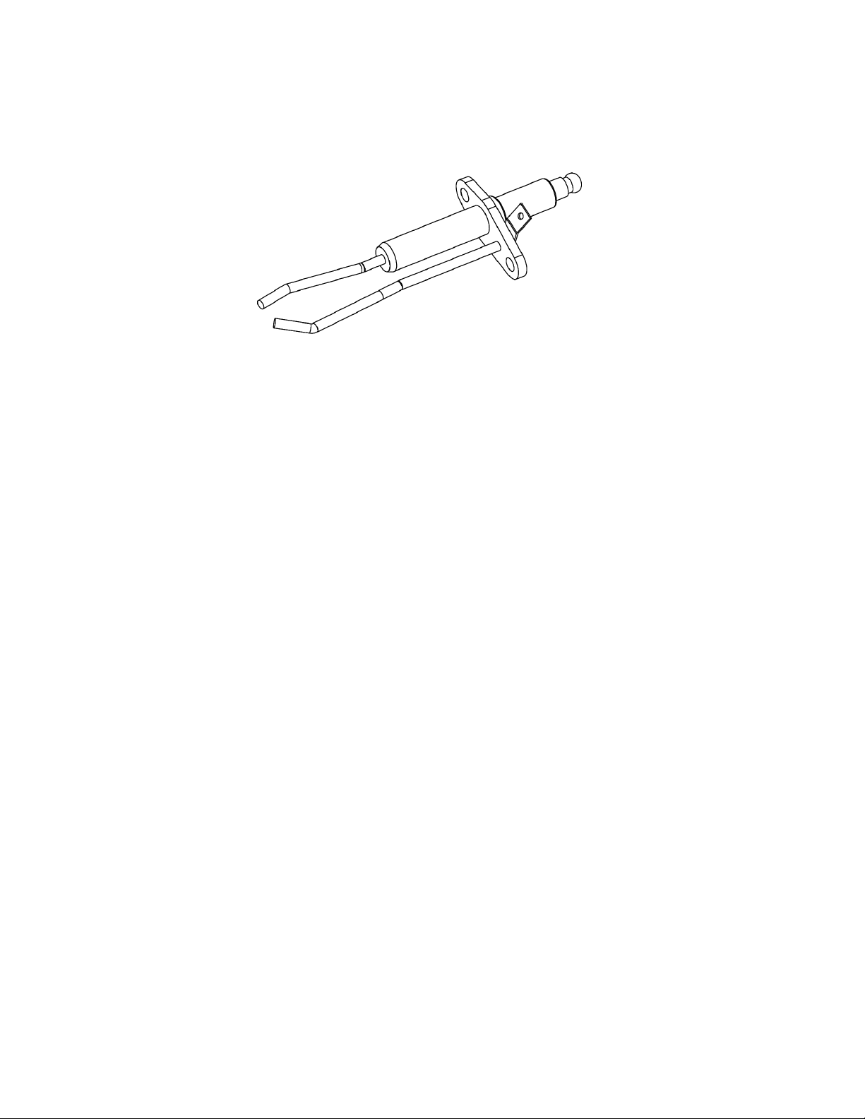
SPARK IGNITER
The XP boilers use a Spark Igniter. The Spark Igniter is made of a ceramic composite material, see Figure 11 below. The Control
System powers the Spark Igniter (120 VAC) from the J5 socket, Terminal 6 on the Control Board to the External Spark Transformer.
Spark Igniters are wearing parts, over time Spark Igniters will wear out and must be replaced as they will no longer generate enough
heat to cause ignition. The life of the Spark Igniter is directly tied to usage; the number of heating cycles. With age and wear, the
resistance of the Spark Igniter, measured in ohms, will rise.
FIGURE 11. SPARK IGNITER
Preliminary Checks for External Ignition Source:
• Open the master switch and remove the connector from J5 socket.
• Ensure that both the manual pilot shutoff valve and the manual main shutoff valves are closed.
• On J5 socket, jumper power to the ignition terminal 6. Disconnect the leadwire to the pilot valve if it is connected to the same
terminal.
• Close the master switch to energize only the ignition transformer.
• If the ignition spark is not strong and continuous, open the master switch and adjust the ignition electrode spark gap setting to
the manufacturer’s recommendation.
• Make sure the ignition electrodes are clean.
• Close the master switch and observe the spark.
• After a continuous spark is obtained, open the master switch and add a jumper on the J5 socket terminal 6 or reconnect the
pilot valve lead wire if it was disconnected.
• Open the manual pilot shutoff valve.
• Close the master switch to energize both the ignition transformer and the pilot valve.
• If the pilot ame does not ignite and if the ignition spark is still continuous, adjust the pilot gas pressure regulator until a pilot
ame is established.
• When the pilot ame ignites properly and stays ignited, open the master switch and remove the jumper(s) from the J5 socket.
• Check for adequate bleeding of the fuel line.
• Reinstall the J5 connector and close the master switch to energize only the ignition transformer.
Service Notes:
• Ensure the wiring and connections between the J5 socket on the Control Board and the Burner Adapter are not broken,
pinched or disconnected.
• Ensure there is approximately 120 VAC at the J5 socket on the Control Board during Spark Igniter Operation.
• An open ame sensing circuit caused by disconnected or loose connectors can also cause ignition failure. Check all wiring
connections between the Flame Sensor and Control Board.
• It is a good practice to check Spark Igniter current when any service or maintenance is being performed. Spark Igniters
are wearing parts, they can cause intermittent ignition failure with age and wear. Replacing the Spark Igniter when current
is lower than 0.55 AC amps is a good preventive maintenance procedure that can prevent loss of hot water and customer
dissatisfaction.
18
Servicing should only be performed by a Qualied Service Agent

GAS VALVE
The 24 Volt Gas Valve on the XP Boilers is DC voltage valve. The Control Board sends 24 VAC to the gas valve. See Figure 6 on
Page 14.
Gas Valve Voltage Test
• Check for 24 VAC supplied to the 24 Volt Gas Valve at pin 2 of the J5 Connector on the Control Board. Using an "AC" volt
meter insert the two test probes into pin 2 of the J5 Connector on the Control Board. 24 VAC should be present.
Gas Valve Removal:
The outlet of the 24 Volt Gas Valve is connected by ange directly to the side of the Venturi and is secured by four - 5/32” hex head
screws. A gas orice with gasket is tted into the gas valve’s outlet ange. The 24 Volt Gas Valve must be removed to inspect the gas
orice. Ensure there is a new gasket on hand before removing the valve. Call the toll free phone number on the back cover of this
manual to order parts. Have the complete Model, Series and Serial number (located on the boiler's rating label) for the boiler being
serviced on hand before calling.
1. Turn off power to the boiler at the boiler's Main Power Supply switch.
2. Loosen the retaining screw for the wiring harness plug on the valve and disconnect the plug.
3. Turn off the supply gas to the boiler at the main gas shutoff valve.
4. Disconnect the supply gas line to the boiler at the boiler's 24 Volt Gas Valve.
5. If the boiler has been installed in a Direct Vent conguration, disconnect the intake air pipe at the intake air connection on
the boiler.
6. Remove the 4 gas valve mounting screws - 5/32” hex head screws.
7. Carefully lift the 24 Volt Gas Valve body off of the Venturi.
8. Follow these steps in reverse order to reinstall the 24 Volt Gas Valve.
9. Run the boiler through a complete cycle before leaving to ensure it is operating properly.
Gas Pressure
The boiler covered in this Service Manual is rated from 920,000 Btu/hr to 3,400,000 Btu/hr input. It is certied for elevations up to
2000 feet (600 meters). For higher elevations call the toll free support phone number shown on the back cover of this manual for
technical assistance.
Models
(XB/XW)
1000, 1300, 1700
2000, 2600, 3400
Type of Gas Inches W.C. kPa Inches W.C. kPa Inches W.C. kPa
Natural
Propane
Manifold Pressure Maximum Supply Pressure Minimum Supply Pressure
Min Fire -0.2 to - 0.3 -0.05 to - 0.07
Max Fire -3.0 to -3.9 -0.75 to -0.97
Min Fire -0.1 to - 0.3 -0.025 to -0.07
Max Fire -3.6 to -4.9 -0.90 to -1.22
TABLE 2. GAS PRESSURE
14.0 3.49 4.0 1.0
14.0 3.49 4.0 2.0
Service Notes:
• The manifold gas pressure is factory set and cannot be adjusted in the eld.
• The manifold gas pressure and the supply gas pressure can be measured at two pressure test ports on the boiler’s 24 Volt
Gas Valve. The manifold pressure test port is closest to the Combustion Blower. There is a needle valve in each test port that
is opened/closed with a small slotted screwdriver. Turn the needle valve counter-clockwise to open the test port valve and
clockwise to close it.
• Manifold gas pressure will run close to 0” W.C. or lower (in a vacuum) depending on the current operating state. This
pressure will be considerably lower, -0.2” W.C. to -4.9” W.C. during the Pre- Purge and Post-Purge operating states when the
Combustion Blower is running at high speed and the 24 Volt Gas Valve is closed.
• There is usually a drop in supply gas pressure noticed when the boiler’s 24 Volt Gas Valve opens during ignition. Seeing a
corresponding rise in manifold pressure during ignition conrms the valve is opening and gas is owing to the Burner.
• A sustained drop in supply gas pressure of 1.5" W.C. or more during boiler running may indicate the supply gas line is
undersized. If the boiler is experiencing a sustained drop in supply gas pressure of 1.5" W.C. or more and the boiler is
experiencing repeated Ignition Failure conditions, intermittent loss of ame or rough starting ensure the supply gas line is sized
in accordance with the current edition of National Fuel Gas Code (ANSI Z223.1/NFPA 54) or the Natural Gas and Propane
Installation Code (CAN/CSA B149.1).
Servicing should only be performed by a Qualied Service Agent
19
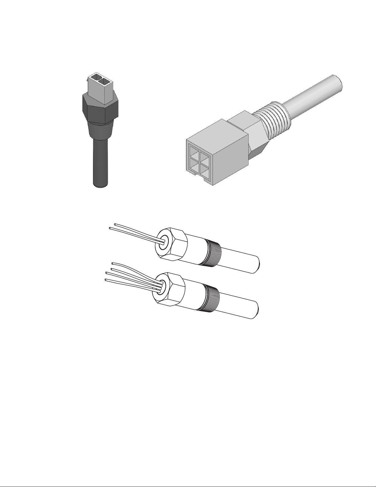
TEMPERATURE SENSORS
INLET / REMOTE TEMPERATURE PROBE
Temperature sensors are 3/4 inch male threaded immersion probes. Temperature probes have embedded temperature sensors
(thermistors). The boiler’s control system monitors these sensors to determine water temperature at various points in the system.
Thermistors are thermally sensitive resistors; as the surrounding temperature rises the resistance of the thermistor (measured in
ohms) will decrease and as the surrounding temperature falls the resistance of the thermistor increases. The Boiler’s Control System
monitors these sensors to determine water temperature at various points in the system.
OUTLET TEMPERATURE PROBE
FIGURE 12. TEMPERATURE SENSORS
Inlet and Outlet Temperature Sensors
All boiler models have two inlet and two outlet temperature sensors for each heat exchanger, factory installed to monitor the water
temperature entering and leaving the boiler. The Inlet Temperature Probe is a temperature sensor only and has two leads. The Outlet
Temperature Probe also contains the manual reset high temperature limit switch and has four leads. The control system displays the
Inlet and Outlet water temperatures sensed from these two sensors on the default Temperatures screen.
Remote Sensors
All boiler models are supplied from the factory with a remote sensor. The remote sensor is used to control system water temperature
for a single boiler in a domestic hot water storage tank or in the return line from a primary/ secondary hydronic heating system.
The boiler will modulate its ring rate in response to the actual system temperature and load conditions. The control system displays
the temperature sensed from the remote sensor as the “Lead Lag” temperature on the default Temperatures screen.
20
Servicing should only be performed by a Qualied Service Agent
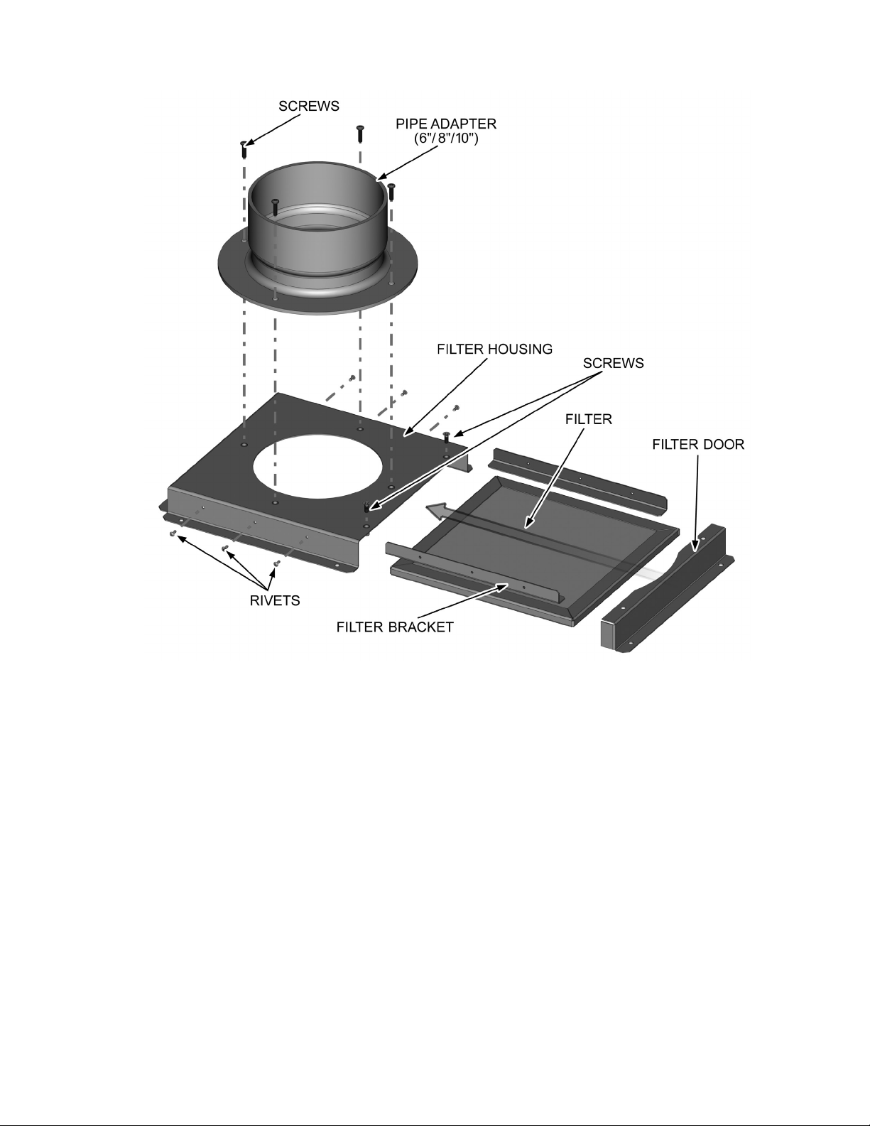
AIR FILTER ASSEMBLY
FIGURE 13. AIR FILTER ASSEMBLY
Air Filter Assembly is mounted on the top panel of the XP Boilers. See Figure 2 on Page 9 and Figure 3 on Page 10. The assembly
includes a lter which slides inside the lter housing and lter brackets. The lter is made of of wire mesh screen and is meant to
block dust particles and other debris from entering through the air intake into the boiler.
Service Notes:
• Ensure the lter is cleaned and water washed every 3 months to avoid the dust and debris getting settled on the lter mesh
screen.
Servicing should only be performed by a Qualied Service Agent
21
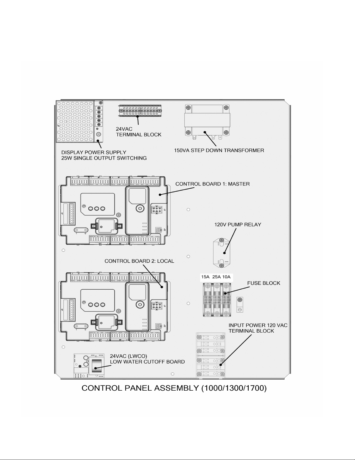
CONTROL PANEL ASSEMBLY
Figure 14, Figure 15 on Page 23 and Figure 16 on Page 24 shows the Control Panels Assemblies for the XP Boilers. The main
components include Control Boards (Master & Local), Display Power Supply, 24 VAC Terminal Block, Step Down Transformer, Pump
Relay, Fuse Block, Input Power 120 VAC Terminal Block, Low Water Cutoff Device and Interlock/Load Control Input (ILK/LCI) Relays.
22
FIGURE 14. CONTROL PANEL ASSEMBLY (1000/1300/1700)
Servicing should only be performed by a Qualied Service Agent
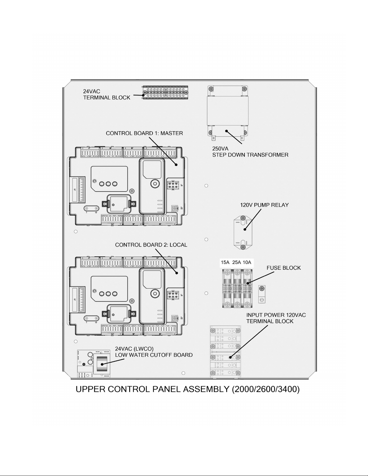
FIGURE 15. UPPER CONTROL PANEL ASSEMBLY (2000/2600/3400)
Servicing should only be performed by a Qualied Service Agent
23
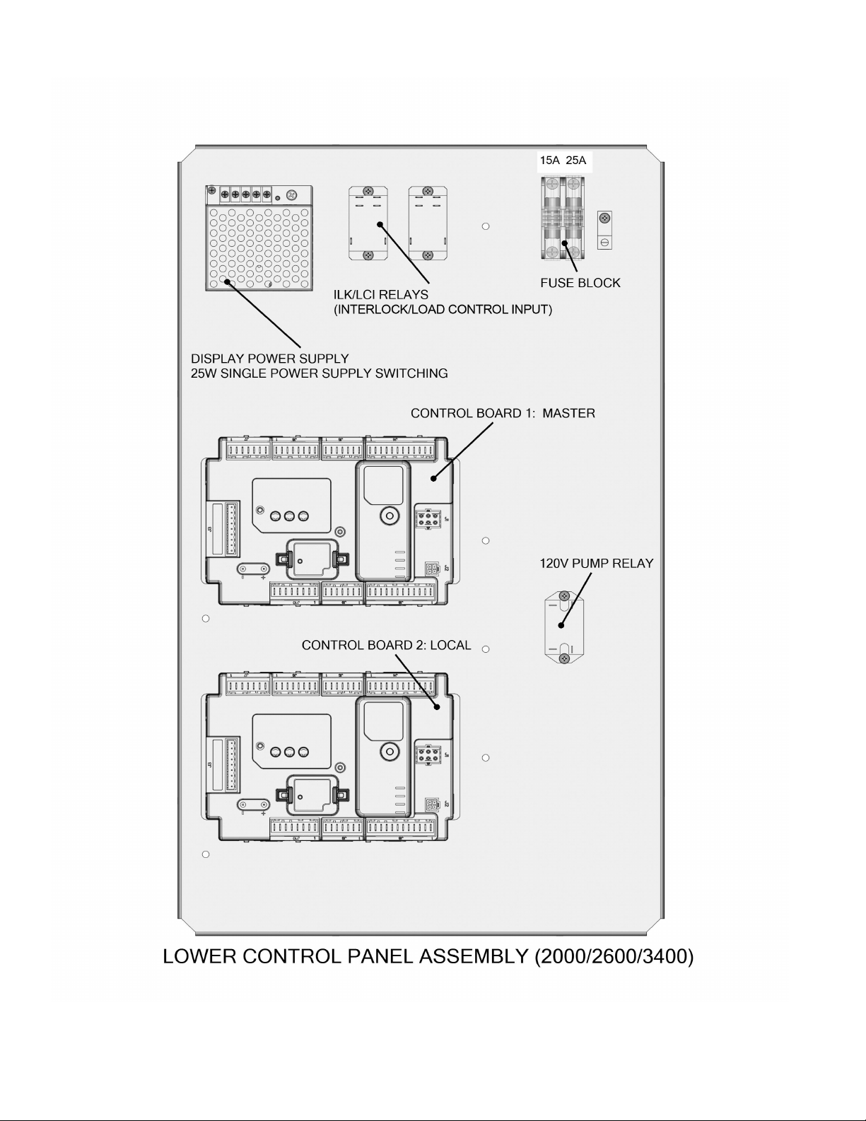
FIGURE 16. LOWER CONTROL PANEL ASSEMBLY (2000/2600/3400)
24
Servicing should only be performed by a Qualied Service Agent
 Loading...