

Page 1

MODELS HW 300, 399, 420, 520, 610, 670
GAS-FIRED COMMERCIAL COPPER BOILERS FOR
HYDRONIC HEATING AND HOT WATER SUPPLY
UP-FLOW MODELS
• INSTALLATION • OPERATION • MAINTENANCE • LIMITED WARRANTY
• INDOOR ONLY
WARNING: If the information in this manual
is not followed exactly, a re or explosion
may result causing property damage,
personal injury or death.
— Do not store or use gasoline or other
flammable vapors and liquids in the
vicinity of this or any other appliance.
— WHAT TO DO IF YOU SMELL GAS
• Do not try to light any appliance.
• Do not touch any electrical switch; do
not use any phone in your building.
• Immediately call your gas supplier
from a neighbor's phone. Follow the
gas supplier's instructions.
• If you cannot reach your gas supplier,
call the re department.
— Installatio n a n d service mu s t be
pe rfo rme d by a qualified installer,
service agency or the gas supplier.
500 Tennessee Waltz Parkway
Ashland City, TN 37015
www.hotwater.com
PLACE THESE INSTRUCTIONS ADJACENT TO BOILER AND
NOTIFY OWNER TO KEEP FOR FUTURE REFERENCE
PRINTED 0210 317693-000
Page 2
SAFE INSTALLATION, USE AND SERVICE
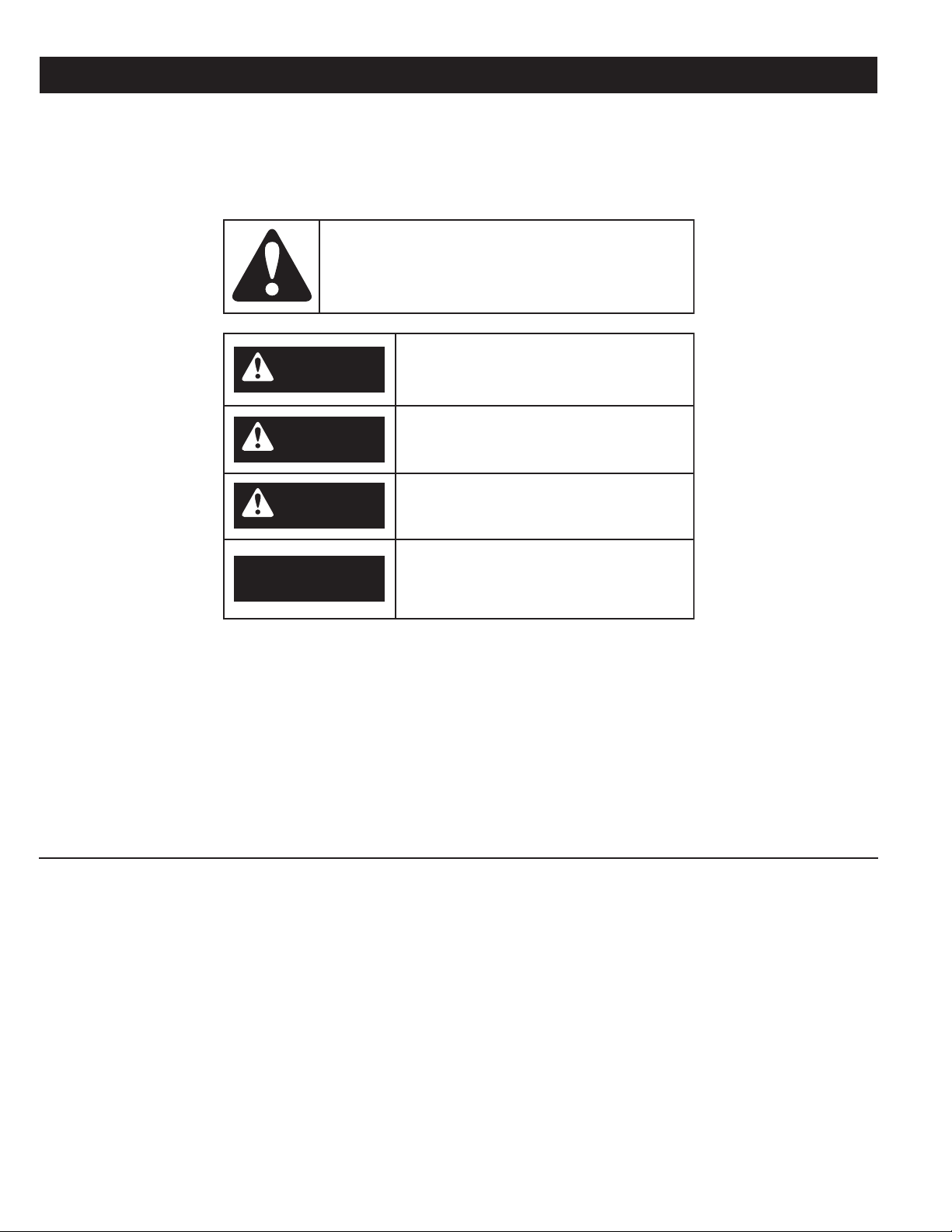
DANGER indicates an imminently
hazardous situation which, if not avoided,
will result in injury or death.
This is the safety alert symbol. It is used to alert you to
potential personal injury hazards. Obey all safety
messages that follow this symbol to avoid possible
injury or death.
WARNING indicates a potentially hazardous
situation which, if not avoided, could result
in injury or death.
CAUTION indicates a potentially hazardous
situation which, if not avoided, could result in
minor or moderate injury.
CAUTION used without the safety alert
symbol indicates a potentially hazardous
situation which, if not avoided, could result in
property damage.
WARNING
CAUTION
CAUTION
DANGER
The proper installation, use and servicing of this water heater is extremely important to your safety and the safety of others.
Many safety-related messages and instructions have been provided in this manual and on your own water heater to warn you and others
of a potential injury hazard. Read and obey all safety messages and instructions throughout this manual. It is very important that the
meaning of each safety message is understood by you and others who install, use, or service this water heater.
All safety messages will generally tell you about the type of hazard, what can happen if you do not follow the safety message, and how
to avoid the risk of injury.
The California Safe Drinking Water and Toxic Enforcement Act requires the Governor of California to publish a list of substances known to
the State of California to cause cancer, birth defects, or other reproductive harm, and requires businesses to warn of potential exposure
to such substances.
This product contains a chemical known to the State of California to cause cancer, birth defects, or other reproductive harm. This appliance
can cause low level exposure to some of the substances listed in the Act.
IMPORTANT DEFINITIONS
• Qualied Installer: A qualied installer must have ability equivalent to a licensed tradesman in the elds of plumbing,
air supply, venting and gas supply, including a thorough understanding of the requirements of the National Fuel Gas
Code or the Natural Gas and Propane Installation Code as it relates to the installation of gas red boilers. The qualied
installer must have a thorough understanding of this instruction manual.
• Service Agency: A service agency also must have ability equivalent to a licensed tradesman in the elds of plumbing,
air supply, venting and gas supply, including a thorough understanding of the requirements of the National Fuel Gas
Code as it relates to the installation of gas red boilers. The service agency must also have a thorough
understanding of this instruction manual, and be able to perform repairs strictly in accordance with the service guidelines
provided by the manufacturer.
• Gas Supplier: The Natural Gas or Propane Utility or service who supplies gas for utilization by the gas burning
appliances within this application. The gas supplier typically has responsibility for the inspection and code approval of
gas piping up to and including the Natural Gas meter or Propane storage tank of a building. Many gas suppliers also
offer service and inspection of appliances within the building.
2
Page 3
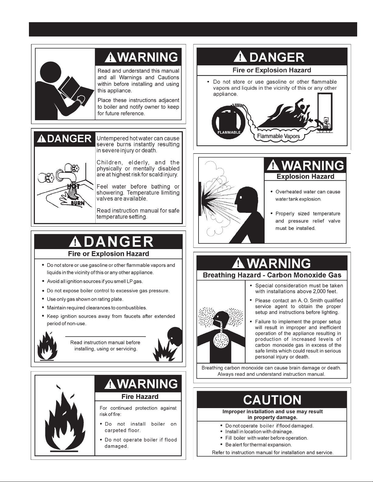
GENERAL SAFETY
3
Page 4

TABLE OF CONTENTS
SAFE INSTALLATION, USE AND SERVICE.......................................................................................................................................................................... 2
GENERAL SAFETY................................................................................................................................................................................................................ 3
TABLE OF CONTENTS .......................................................................................................................................................................................................... 4
DIMENSIONS AND CAPACITY DATA .................................................................................................................................................................................... 5
INTRODUCTION .................................................................................................................................................................................................................... 7
Grounding Instructions ................................................................................................................................................................................................... 7
Correct Gas .................................................................................................................................................................................................................... 7
Precautions .................................................................................................................................................................................................................... 7
Liquid Petroleum Gas Models ........................................................................................................................................................................................ 7
High Altitude Installations ............................................................................................................................................................................................... 7
CONTROLS AND FUNCTION ................................................................................................................................................................................................ 8
High Limit ....................................................................................................................................................................................................................... 8
Intermittent Ignition Control Module ............................................................................................................................................................................... 8
Thermal Balancer ........................................................................................................................................................................................................... 9
Auto Reset High Limit Control ........................................................................................................................................................................................ 9
Safety Flow Switch ......................................................................................................................................................................................................... 9
Safety Relief Valves...................................................................................................................................................................................................... 10
Tank Temperature Control .............................................................................................................................................................................................11
Thermometers (not installed) ....................................................................................................................................................................................... 12
DRAIN VALVE ...................................................................................................................................................................................................................... 12
GENERAL ............................................................................................................................................................................................................................ 12
Required Ability ............................................................................................................................................................................................................ 12
Location ........................................................................................................................................................................................................................ 12
Air Requirements .......................................................................................................................................................................................................... 13
Chemical Vapor Corrosion............................................................................................................................................................................................ 13
Installation Clearances ................................................................................................................................................................................................. 14
Leveling ........................................................................................................................................................................................................................ 14
System Connections .................................................................................................................................................................................................... 14
VENTING ............................................................................................................................................................................................................................. 14
Venting the Boiler ......................................................................................................................................................................................................... 14
Venting Maintenance .................................................................................................................................................................................................... 16
Venting Sidewall ........................................................................................................................................................................................................... 16
Venting System ............................................................................................................................................................................................................ 16
Venting Tables .............................................................................................................................................................................................................. 17
SYSTEM INSTALLATIONS .................................................................................................................................................................................................. 18
Installations .................................................................................................................................................................................................................. 18
Conventional ........................................................................................................................................................................................................ 18
Linear Temp .......................................................................................................................................................................................................... 18
Water Supply Line ................................................................................................................................................................................................ 19
Expansion Tank .................................................................................................................................................................................................... 19
Vent Valves ........................................................................................................................................................................................................... 20
Manifold Headers ................................................................................................................................................................................................. 20
Cooling Piping ...................................................................................................................................................................................................... 20
Circulating Pump .................................................................................................................................................................................................. 20
Gas Connections .......................................................................................................................................................................................................... 20
Gas Supply Line Purging and Sizing ............................................................................................................................................................................ 21
Gas Pressure Regulators ............................................................................................................................................................................................. 22
WIRING ................................................................................................................................................................................................................................ 23
WIRING DIAGRAMS ....................................................................................................................................................................................................... 24-33
PIPING ............................................................................................................................................................................................................................34-39
OPERATION AND START-UP INSTRUCTIONS .................................................................................................................................................................. 39
Important ...................................................................................................................................................................................................................... 39
Filling the System ......................................................................................................................................................................................................... 39
Pilot Alignment and Main Burner .......................................................................................................................................................................................... 39
Lighting Instructions ................................................................................................................................................................................................ 43-44
Checking and Adjusting Input ....................................................................................................................................................................................... 41
Operating Sequence .................................................................................................................................................................................................... 42
REMOVAL OF EXISTING BOILER FROM A COMMON VENTING SYSTEM ..................................................................................................................... 45
GENERAL MAINTENANCE ................................................................................................................................................................................................. 45
Cleaning and Flushing Instructions ...................................................................................................................................................................................... 46
PRE TROUBLESHOOTING ................................................................................................................................................................................................. 46
TROUBLESHOOTING .................................................................................................................................................................................................... 47-54
LIMITED WARRANTY .......................................................................................................................................................................................................... 55
4
Page 5
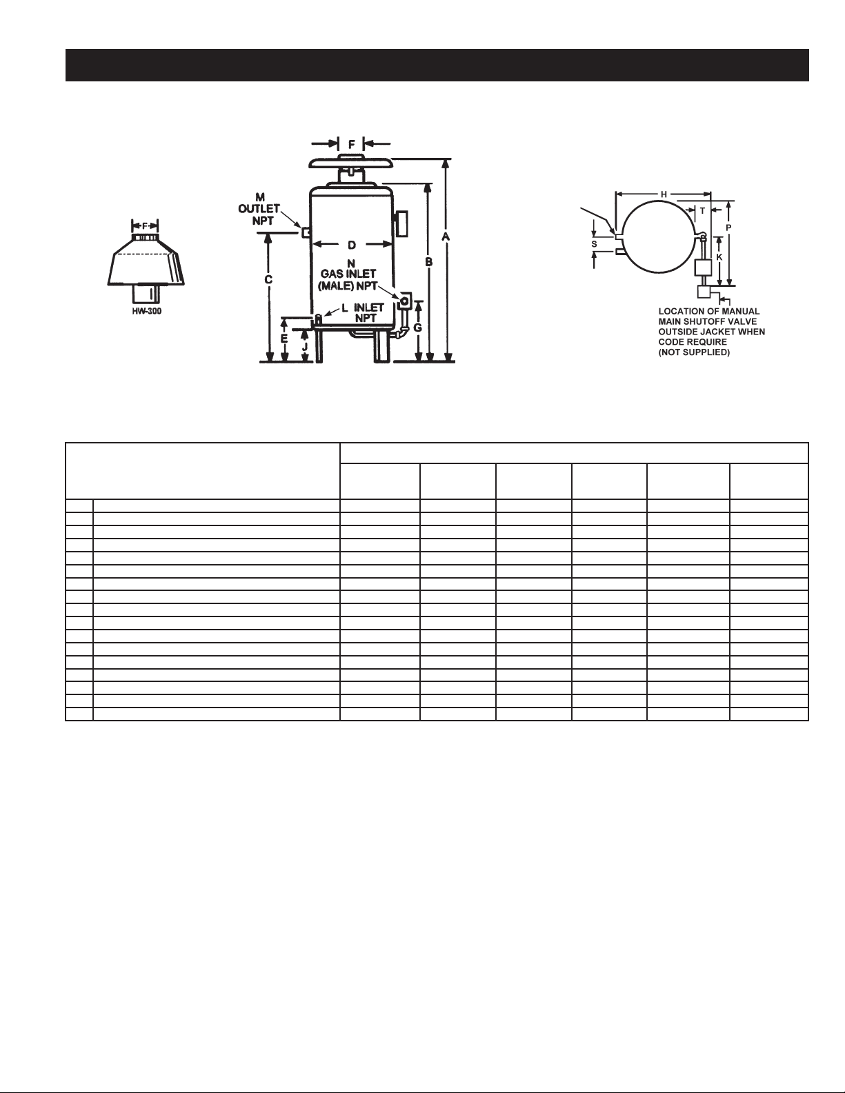
DIMENSIONS AND CAPACITY DATA
EXTRA OPENING
FOR THERMOMETER
AND RELIEF VALVE
HW-520, 610
AND HW--670
TABLE 1
MODELS
DIMENSIONS IN INCHES
A Overall height 65 (1651) 57-1/8 (1451) 57-1/8 (1451) 68-5/16 (1735) 67 (1702) 64-3/4 (1645)
B Height to Top of Jacket 43-1/4 (1099) 45-1/8 (1146) 45-1/8 (1146) 56-1/4 (1429) 56-1/4 (1429) 56-1/4 (1429)
C Floor to Center Line Water Inlet 36 (914) 38-3/4 (984) 38-3/4 (984) 46 (1168) 46 (1168) 46 (1168)
D Diameter of Jacket 25-1/4 (641) 27 (686) 27 (686) 27 (686) 27 (686) 27 (686)
E Floor to Center Line Water Outlet 12 (305) 12 (305) 12 (305) 12 (305) 12 (305) 12 (305)
F Draft Diverter Outlet Diameter 8 (203) 10 (254) 10 (254) 10 (254) 12 (305) 12 (305)
G Floor to Center Line Gas Inlet 16-1/2 (419) 16-3/4 (425) 16-3/4 (425) 18 (457) 18 (457) 18 (457)
H Overall Depth 29-5/8 (753) 31-1/2 (800) 31-1/2 (800) 36-1/2 (927) 36-1/2 (927) 36-1/2 (927)
J Support Height 9 (229) 9 (229) 9 (229) 9 (229) 9 (229) 9 (229)
K Width of Control String (approx.) 14 (356) 14 (356) 14 (356) 11 (279) 11 (279) 11 (279)
L Pipe Size of Water Inlet (NPT) 1-1/4 1-1/2 1-1/2 2 2 2
M Pipe Size of Water Outlet (NPT) 1-1/4 1-1/2 1-1/2 2 2 2
N Pipe Size of Gas Inlet (NPT) 3/4 1 1 1 1 1
P Control String Plus 1/2 Jacket Diameter (approx.) 26-5/8 (676) 27-1/2 (699) 27-1/2 (699) 24-1/2 (622) 24-1/2 (622) 24-1/2 (622)
S Horizontal Length between Water Inlet and Outlet 5-3/8 (137) 5-1/2 (140) 5-1/2 (140) 5-3/4 (146) 5-3/4 (146) 5-3/4 (146)
T Control String from Jacket 5 (127) 5 (127) 5 (127) 7 (178) 7 (178) 7 (178)
Approximate shipping weight lbs. (Kilograms) 240 (109) 291 (132) 291 (132) 361 (164) 361 (164) 361 (164)
NOTE: All dimensions in inches (millimeters) except pipe size which is NPT
HW-300 HW-399 HW-420 HW-520
PROPANE
HW-610/670
NATURAL
HW-610/670
5
Page 6
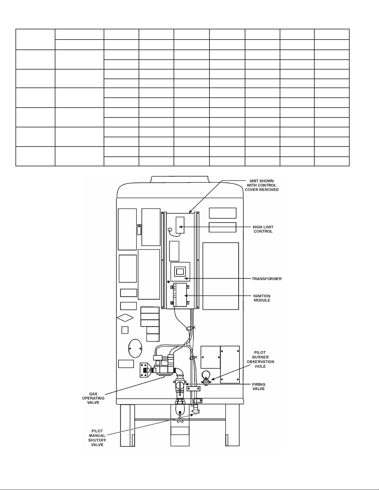
TABLE 2, RECOVERY CAPACITIES
Input °F 20 40 50 60 70 80
Model
BTUH (kW) °C 11.1 22.2 27.7 33.3 38.8 44.4
HW 300 300,000 (88)
HW 399 399,000 (117)
HW 420 420,000 (123)
HW 520 520,000 (152)
HW 610 610,000 (179)
HW 670 660,000 (193)
GPH 1439 719 576 480 411 360
LPH 5448 2724 2179 1816 1556 1362
GPH 1914 957 765 638 547 478
LPH 7245 3623 2898 2415 2070 1811
GPH 2014 1007 806 671 576 504
LPH 7627 3813 3051 2542 2179 1907
GPH 2494 1247 998 831 713 624
LPH 9443 4721 3777 3148 2698 2361
GPH 2926 1463 1170 975 836 731
LPH 11077 5538 4431 3692 3165 2769
GPH 3165 1583 1266 1055 904 791
LPH 11985 5992 4794 3995 3424 2996
COMPONENT LOCATION
FIGURE 1.
6
Page 7
INTRODUCTION
This design complies with the current edition of the ANSI Z21.13
low-pressure boiler standard.
Compliance under this standard implies that when the boiler
underwent test, the gas manifold and control assembly pro vided
on the boiler met safe lighting and other performance criteria.
Detailed installation diagrams are found in this manual. These
diagrams will serve to provide the installer a reference for the
materials and methods of piping necessary. It is essential that
all water, gas piping and wiring be installed as shown on the
diagrams. You should thoroughly read and understand this manual
before installation and/or operation of this boiler.
The factory warranty will be void if the boiler(s) have been
improperly installed or operated.
In addition to these instructions, the boiler(s) shall be installed
in accordance with those installation regulations in force in the
local area where the installation is to be made. These shall be
carefully followed in all cases. Authorities having jurisdiction
should be consulted before installations are made.
In the absence of local codes, the installation must comply with the
current editions, as follows:
In the United States:
The National Fuel Gas Code, ANSI Z223.1/NFPA 54 and the
National Electric Code, NFPA 70.
In Canada:
Installation Code CAN/CSA B149.1 and Canadian Electrical Code,
CSA C22.1.
GROUNDING INSTRUCTIONS
IF THE BOILER HAS BEEN EXPOSED TO FLOODING, IT
MUST BE REPLACED.
LIQUEFIED PETROLEUM GAS MODELS
Boilers for propane or liquefied petroleum gas (LPG) are different
from natural gas models. A natural gas boiler will not function
safely on LP gas and no attempt should be made to convert a
boiler from natural gas to LP gas.
LP gas m ust be use d w i th g reat cau tion . I t is h ighl y
ex plo sive and h eavie r tha n air. It col lects f irs t in the low
ar eas m aki ng its odo r dif ficul t to det ect a t nose lev el.
If LP gas is prese nt or even sus pec ted, do not atte mpt
to fi nd the c aus e you rself . Lea ve the b uil ding, le avi ng
do ors open to ve nti late, t hen cal l your gas sup pli er o r
se rvi ce a gent. Kee p ar ea c lea r un til a se rvice cal l ha s
been made.
At ti mes you ma y not be ab le to smel l an LP gas leak.
On e c aus e is odor fad e, whic h i s a los s o f t he chemic al
od ora nt th at give s LP ga s its di stinc tiv e sme ll. An oth er
ca use can b e y our p hys ica l con dit ion, suc h a s hav ing
a c o ld o r d imin i shin g s ense o f smel l with a g e. F o r
the se r eas o ns, the u se o f a p rop a ne g as d etec tor i s
recommended.
IF YOU E XPE RIENC E AN OUT OF GAS S ITU ATION, D O
NO T T RY TO RELIGHT APP LIA NCES Y OUR SELF. Call
yo ur l oca l serv ice age nt. On ly t rained LP profe ssi ona ls
sh oul d co ndu ct t he r equ ired safety checks in accord anc e
with industry standards.
HIGH ALTITUDE INSTALLATIONS
This boiler must be grounded in accordance with the National Electrical
Code, Canadian Electrical Code and/or local codes. Correct wiring is
imperative for proper operation.
This boiler must be connected to a grounded metal, permanent
wiring system, or an equipment grounding conductor must be run
with the circuit conductors and connected to the equipment grounding
terminal or lead on the boiler.
CORRECT GAS
MAKE SURE THE GAS ON WHICH THE BOILER WILL
OPERATE IS THE SAME AS THAT SPECI FIED ON THE
BOILER RATING PLATE. DO NOT INSTALL THE BOILER IF
EQUIPPED FOR A DIFFERENT TYPE OF GAS — CONSULT
YOUR SUPPLIER.
PRECAUTIONS
IF THE UNIT IS EXPOSE D TO THE FOLLOWING, D O NO T
OPERATE UNTIL ALL CORRECTIVE S TE PS HAVE B EE N
MADE BY A QUALIFIED SERVICEMAN:
1. EXPOSURE TO FIRE.
2. IF DAMAGED.
3. FIRING WITHOUT WATER.
4. SOOTING.
Rated inputs are suitable up t o 2000 feet (61 0 m) elevation.
Co nsu lt the factory for i nst all ation a t alt itu des ove r 200 0
feet (610 m).
7
Page 8
HIGH ALTITUDE INSTALLATIONS
IN CANADA
Acceptance of these models for use at altitudes above 2000 feet
(600 m) is based on eld test of the individual installation by the
provincial/state authority having jurisdiction.
IN THE U.S.A.
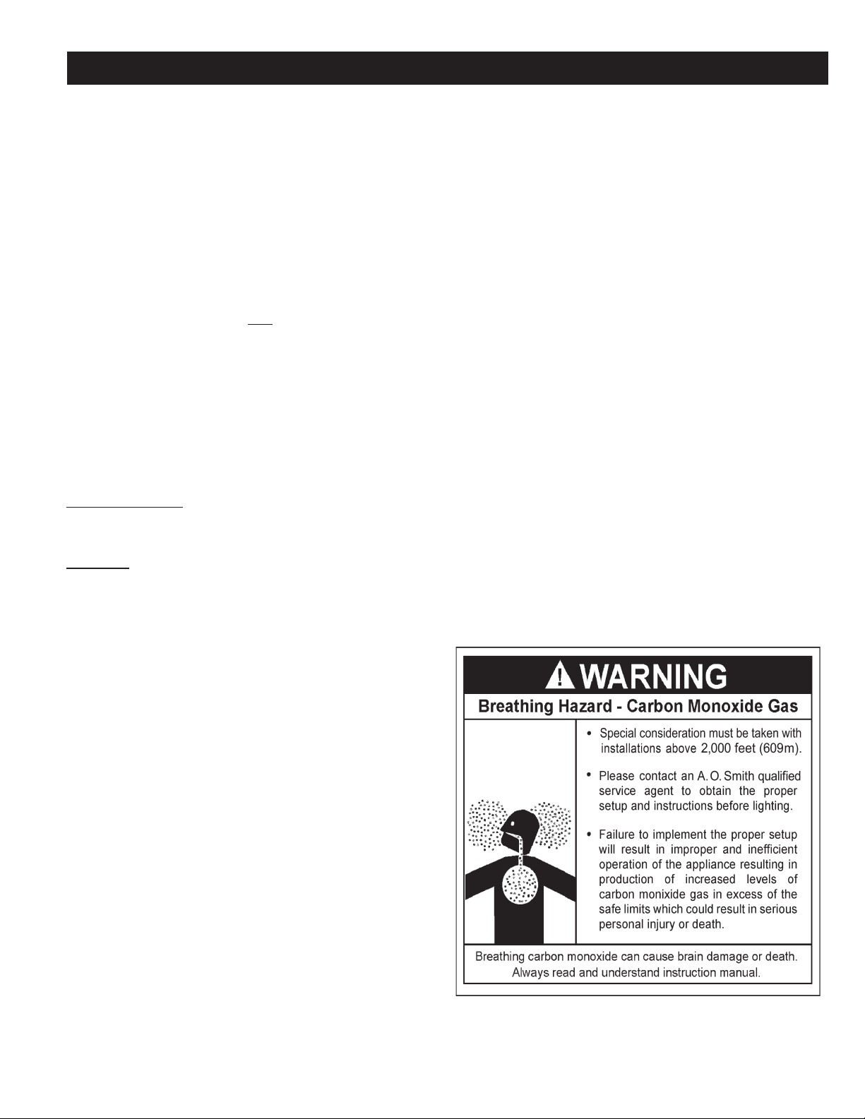
WARNING
INSTALLATIONS ABOVE 2000 FEET REQUIRE REPLACEMENT
OF THE BURNER ORIFICES IN ACCORDANCE WITH THE
CURRENT EDITION OF THE NATIONAL FUEL GAS CODE
(ANSI Z223.1). FAILURE TO REPLACE THE ORIFICES WILL
RESULT IN IMPROPER AND INEFFICIENT OPERATION OF THE
APPLIANCE RESULTING IN THE PRODUCTION OF INCREASED
LEVELS OF CARBON MONOXIDE GAS IN EXCESS OF SAFE
LIMITS WHICH COULD RESULT IN SERIOUS PERSONAL
INJURY OR DEATH.
For specic orice requirements, please refer to the appropriate
section of the National Fuel Gas Code ANSI Z223.1.
You should contact your gas supplier for any specic changes which
may be required in your area.
Ratings specified by manufacturers for most boilers apply for
elevations up to 2000 feet (600 m). For elevations above 2000 feet
(600 m) ratings must be reduced by a rate of 4% for each 1000 feet
(300 m) above sea level.
Example: If a boiler is rated at 610,000 Btu/hr. at sea level, to operate
the boiler at 5000 feet (1500 m) it must be derated by 20% (4% x 5)
to a new rating of 488,000 Btu/hr.
A. O. Smith does build some models specically for high altitude
service. Please check the rating plate before making changes.
The input reduction is primarily achieved by reducing the size
of the main burner orifices. To do this, the main burner orifices
re qui re repl aceme nt with orific es size d for the pa rticu lar
installation elevation. When ordering, be sure to state the model
number and the altitude of the location where the boiler is being
installed.
Upon field deration of the boiler, adjustment to the gas pressure
regulator is required. See CHECKING AND ADJUSTING
THE INPUT in this manual for inlet and manifold pressure
requirements. Also, due to the input rating reduction required at
high altitudes, the output rating of the appliance is also reduced
and should be compensated for in the sizing of the equipment
for applications.
CONTROLS AND FUNCTION
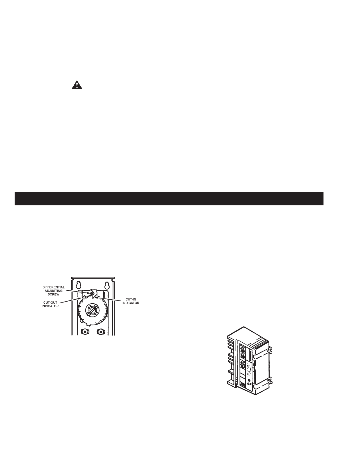
AUTO RESET HIGH LIMIT
Th e hig h l im it is a safety devic e w ired in s eries wit h t he
ignition system. Set the high limit control to approximately 10
ab ove the maxi mum d esigned system temper at ure. If th e
boi ler out let wa ter te mpe r atu re shou l d exc e ed the hig h
limit setting, the main gas valve will close but the circulator
will continue to operate. Maximum adjustable setting is 115
(239°F) cut-out with a 3
0
C (50F) to 250C (450F) adjustable
differential, see Figure 2.
FIGURE 2.
INTERMITTENT IGNITION CONTROL MODULE
The Honeywell S-8600 control module contains the electronic
components of the system and also serves as a control wiring system
for the controls mounted on the heater. The control module performs
the following functions:
0
F
0
C
3. Opens the pilot valve.
4. Discontinues ignition spark when the pilot flame is established.
The S-8600 control used on propane gas models provides
safety lockout if the pilot fails to ignite within the pilot flame
estab lishing period. The S-8600 control used on natural
gas models continues trial for ignition until pilot flame
is established.
5. After proof of pilot ame, opens then main valve.
6. On a power loss, shuts the heater down. When power is restored
it will begin a new ignition cycle.
7. On a loss of ame, shuts off main gas and starts trial for pilot ignition.
PLEASE SEE TROUBLESHOOTING SECTION FOR MORE
INFORMATION.
1. Checks for safe-start by sensing for a false ame condition on
start-up.
2. Generates a potential of 15,000 volts for spark ignition of the
pilot burner.
S-8600 INTERMITTENT IGNITION
CONTROL MODULE (IID)
FIGURE 3.
8
Page 9
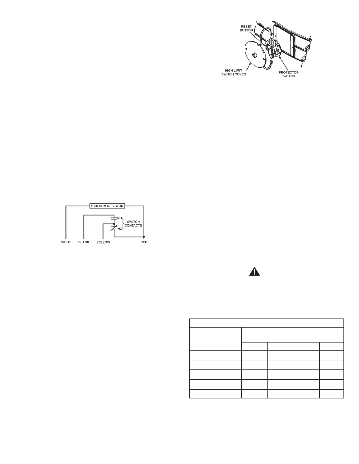
THERMAL BALANCER
Figure 4 shows the internal wiring of the thermal balancer. The
device may be tested after disconnecting the four leads from their
respective terminals on the unit.
1. Apply a test light to the yellow and red leads.
• The lamp should light as the contact in this circuit is normally
closed when the resistor is cool.
2. Apply a light to the black and yellow leads.
• The lamp should not light as the contact in this circuit is normally
open when the resistor is cool.
3. Remove the test light.
4. Apply 120 volts to the white and red leads which power the 1900
ohm resistor. After a warming period the contacts of the thermal
balancer should operate.
5. Remove the test light.
6. Apply the test light as described in steps 1 and 2.
While the resistor is still warm the lamp indications should be the
opposite as described previously.
FIGURE 4.
HIGH LIMIT SWITCH
FIGURE 5.
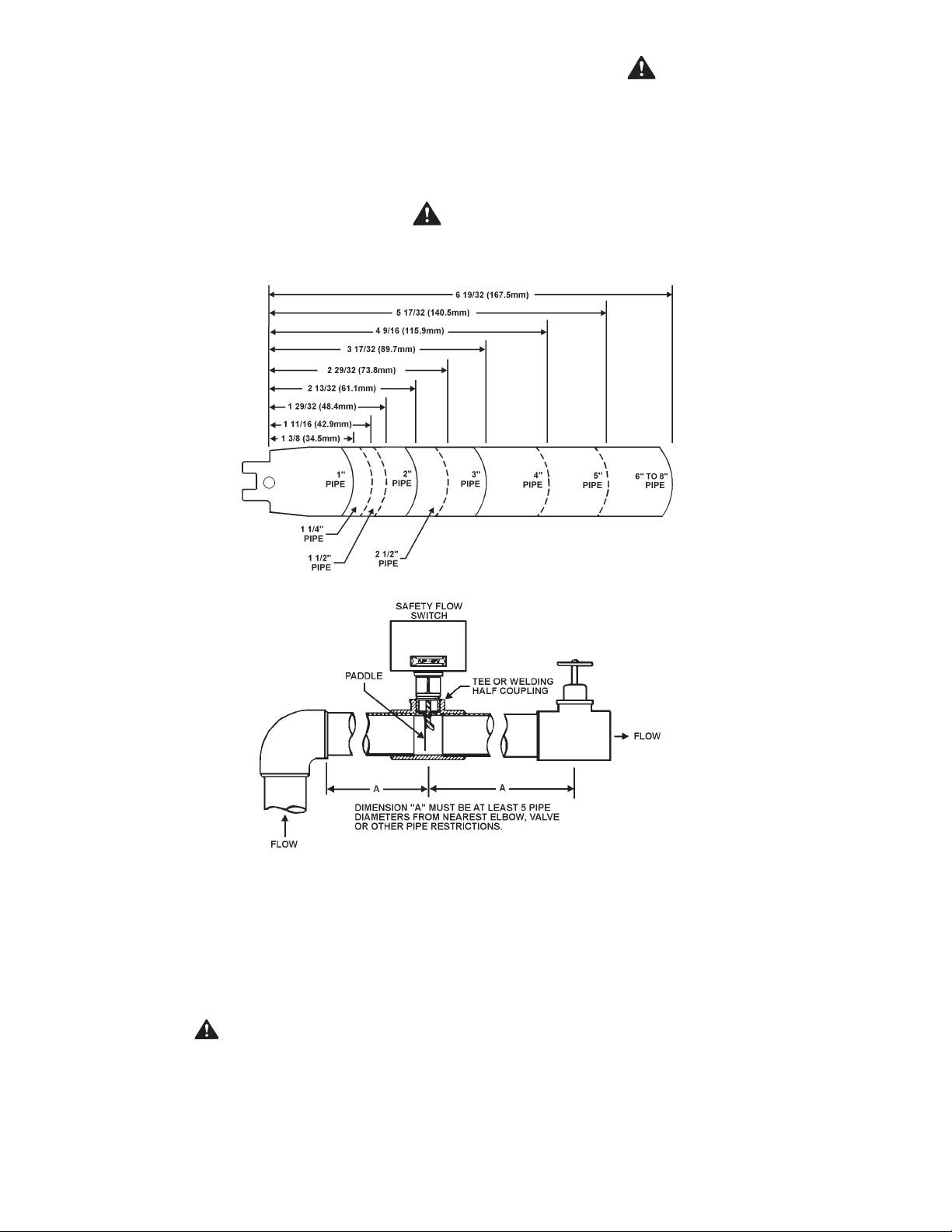
SAFETY FLOW SWITCH
The safety ow switch is a safety device which must be installed at
the water outlet of the unit to prevent main burner operation in the
event of inadequate water ow through the unit.
An accessory package containing a safety ow switch is available
for this application.
This switch may be mounted in a horizontal pipe line or a vertical
pipe line with upward water ow. Do not install the switch where the
water ow is downward.
For proper performance mount the switch in a section of pipe where
there is a straight run of at least 5 pipe diameters on each side of the ow
switch (i.e. do not locate adjacent to valves, elbows, orices, etc.).
The ow switch shall be mounted in a standard 1-1/2" x 1-1/2" x 1"
tee for a 1-1/2" pipe application. For larger pipe sizes use a reducing
tee in order to keep the switch as close to the pipe as possible. Install
the ow switch in the branch (top) opening of the reducing tee and
provide adequate paddle length in the ow stream. For example in
a 2" pipe installation use a 2" x 2" x 1" reducing tee. For 2", or 3"
pipe use paddle segments as supplied. For other pipe sizes (i.e.
1-1/4", 1-1/2" and 2-1/2") trim the paddle to the proper pipe size, see
Figure 6 on page 10. If a standard tee is used, install a face or hex
bushing in the top opening. The paddle must be adjusted or trimmed
to the size of the pipe in which it will be installed.
MANUAL RESET HIGH LIMIT
This boiler is equipped with a manual reset high limit switch,
located under the small cover on the side of the jacket, see
Fi gur e 5. T his devi ce p rov ide s posi tiv e s hut dow n of the
boiler in the event of boiler or system malfunction. Should the
surface temperatu re of the copper t ubing hea t exc ha nger
rea ch 25 0 °F (12 0°C), th e h i gh li mit sw itc h will ac tiv ate ,
the gas valve will c lose, the pilot and main burners will be
extinguished. If the high limi t switch should shut of f unit, check
the following conditions:
• No water in boiler.
• Restricted water flow through the boiler.
• Improper wiring (boiler firing without circulator
operating).
• Pump failure.
After correcting failure condition remove the protector switch cover
and push the reset button. The high limit switch may be reset after
the coil surface cools to 6°F (3.3°C) below the trip setting.
CAUTION
Any part of the paddle must not touch the pipe or any restrictions in
the pipe. Screw the ow switch in position so the at of the paddle
is at right angles to the ow. The arrow on the side case must point
in the direction of the ow.
TABLE 3 - SAFETY FLOW SWITCH
Minimum Pipe Rate
Model Number
Contacts Closed
(Flow)
Contacts Open
(No Flow)
GPM LPM GPM LPM
HW-300 5.8 22.0 3.7 14.0
HW-399 7.5 28.4 5.0 18.9
HW-420 7.5 28.4 5.0 18.9
HW-520 13.7 51.9 9.5 36.0
HW-610/670 13.7 51.9 9.5 36.0
The safety ow switch may be eld adjusted to obtain higher
minimum ow rates than those shown in table 3.
9
Page 10
To adjust the ow rate setting:
1. Remove the ow switch cover.
2. For higher ow rate - turn the range adjusting screw clockwise.
CAUTION
The switch is factory set at approximately the minimum ow rate, see
Table 3 on page 9. It must not be set lower than the factory setting as
this may result in the switch failing to return at 'no ow' condition.
3. For lowe r flow rat e - tur n the rang e adjus tin g sc rew
counterclockwise.
CAUTION
Paddle must be trimmed at the dotted arc. It must not touch the pipe or have any restriction when installed.
4. Replace ow switch cover. Where units are installed in multiples,
each boiler must be individually protected by a safety ow switch.
FIGURE 6.
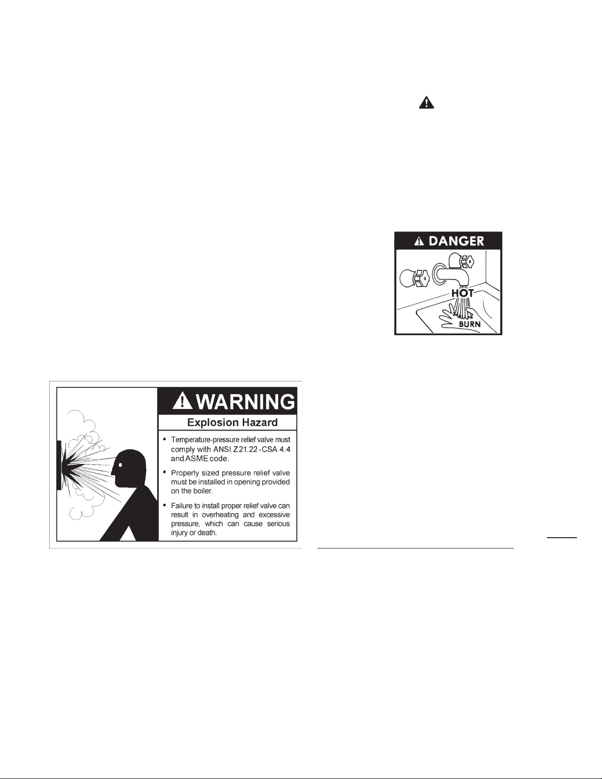
SAFETY RELIEF VALVES
Your local code authority may have other specic relief valve
requirements not covered below.
WARNING
THE PURPOSE OF A SAFETY RELIEF VALVE IS TO AVOID
EXCESSIVE PRESSURE OR TEMPERATURE INTO THE STEAM
RANGE WHICH MAY CAUSE SCALDING AT FIXTURES, TANK
EXPLOSION, SYSTEM OR BOILER DAMAGE.
TO AVOID SCALDING OR WATER DAMAGE A DRAIN LINE MUST
BE CONNECTED TO A RELIEF VALVE TO DIRECT DISCHARGE
TO A SAFE LOCATION. A DRAIN LINE MUST NOT BE REDUCED
FROM THE SIZE OF THE VALVE OUTLET AND IT MUST NOT
CONTAIN ANY VALVES BETWEEN THE BOILER AND THE
RELIEF VALVE OR THE RELIEF VALVE AND THE DRAIN EXIT.
IN ADDITION, THERE SHOULD NOT BE ANY RESTRICTIONS
IN A DRAIN LINE NOR SHOULD IT BE ROUTED THROUGH
AREAS WHERE FREEZING CONDITIONS MIGHT OCCUR. DO
NOT THREAD OR CAP THE DRAIN LINE EXIT. RESTRICTING
OR BLOCKING A DRAIN LINE WILL DEFEAT THE PURPOSE OF
THE RELIEF VALVE AND MAY CREATE AN UNSAFE CONDITION.
INSTALL A DRAIN LINE WITH A DOWNWARD SLOPE SUCH THAT
IT NATURALLY DRAINS ITSELF.
If any safety relief valve is replaced, the replacement valve must comply
with the current editions of the ASME Boiler and Pressure Vessel
10
Page 11
Code, Section IV or CSA B51, as applicable. Select a relief valve with
a discharge NOT less than the boiler input, and a pressure rating NOT
exceeding the working pressure of any component in the system.
A. O. Smith supplies a 125 psi relief valve for hot water supply systems
and 50 psi relief valve for space heating application.
An ASME rated temperature and pressure relief valve must be installed
on each and every water storage tank in a hot water supply system.
The storage tank temperature and pressure (T & P) relief valve must
comply with the applicable contruction provisions of the Standard
for Relief valves and Automatic Gas Shutoff Devices for Hot Water
Supply Systems, Z21.22 - CSA 4.4. The T & P valve must be of the
automatic reset type and not embody a single-use type of fusible
plug, cartridge or linkage.
The T & P relief valve should have a maximum temperature rating
of 100°C (210°F), a pressure rating NOT exceeding the lowest
rated working pressure of any system component, and a discharge
capacity exceeding the total input of the water boilers supplying
water to the storage tank.
Locate the T & P relief valve (a) in the top of the storage tank or (b)
in the side of the tank on centerline within upper 6 inches from the
top of the tank. See Figures 28 to 33, Pages 34 to 38. Tapping shall
be threaded in accordance with the latest version of the Standard for
Pipe Threads, General Purpose (inch), ANSI/ASME B.120.1.
TANK TEMPERATURE CONTROL
The water temperature in the storage tank is controlled by the Tank
Temperature Control. The sensing element is mounted inside the
hot water storage tank.
DANGER
HOT WATER TEMPERATURES REQUIRED FOR AUTOMATIC
DISHWASHER AND LAUNDRY USE CAN CAUSE SCALD BURNS
RESULTING IN SERIOUS PERSONAL INJURY AND/OR DEATH.
THE TEMPERATURE AT WHICH INJURY OCCURS VARIES
WITH THE PERSON’S AGE AND TIME OF EXPOSURE. THE
SLOWER RESPONSE TIME OF CHILDREN, AGED OR DISABLED
PERSONS INCREASES THE HAZARDS TO THEM. NEVER ALLOW
SMALL CHILDREN TO USE A HOT WATER TAP, OR TO DRAW
THEIR OWN BATH WATER. NEVER LEAVE A CHILD OR DISABLED
PERSON UNATTENDED IN A BATHTUB OR SHOWER.
Mark location with a class III Label. See ANSI Z21.10.1, Part 1,
Marking, See CAN/CSA B149.
The tank temperature control is adjustable from 100°F (37.7°C) to
220°F (104.4°C). It is recommended that lower water temperatures
be used to avoid the risk of scalding. It is further recommended, in all
cases, that the water temperature be set for the lowest temperature
which satises the user’s hot water needs. This will also provide the
most energy efcient operation of the water heater and minimize
scale formation.
THE WATER HEATER SHOULD BE LOCATED IN AN AREA WHERE
THE GENERAL PUBLIC DOES NOT HAVE ACCESS TO SET
TEMPERATURES. SETTING THE WATER TEMPERATURE AT
120°F (49°C) WILL REDUCE THE RISK OF SCALDS. Some states or
provinces require settings at specic lower temperatures. Below you
will nd listed the approximate time-to-burn relationship for normal
adult skin. Valves for reducing point-of-use temperature by mixing
cold and hot water are available. Also available are inexpensive
devices that attach to faucets to limit hot water temperatures. Contact
a licensed plumber or the local plumbing authority.
11
Page 12
Water Temperature
OVER: 170°F (77°C)
160°F (71°C)
150°F (65°C)
140°F (60°C)
130°F (54°C)
120°F (49°C)
USE ANTI-SCALD VALVE(S) in the hot water system to reduce
the risks of scalds at points of use such as lavatories, sinks
and bathing facilities.
A change in water temperature in the storage tank lower than
the Tank Temperature Control setting will c ause the sensor to
close its contacts and consequently energize the boiler.
If the Tank Temperature Control is out of calibration, replace it
with a new one; do not attempt to fix this control.
SHOULD OVERHEATING OCCUR OR THE GAS SUPPLY FAIL
TO SHUT OFF, TURN O FF THE MANUAL G AS CONTROL
VALVE TO THE APPLIANCE.
Time to Produce 2nd & 3rd
Degree Burns on Adult Skin
Nearly Instantaneous
About 1/2 second
About 1-1/2 seconds
Less than 5 seconds
About 30 seconds
More than 5 minutes
WARNING
THERMOMETERS
Thermometers should be obtained and field installed as shown
in the installation diagrams.
The rmom e ter s are ins tall e d in th e sys tem a s a mea n s
of de t e ctin g a p ossi b l e limi n g condi t i on in t h e boile r.
An incr ease of 5°F (3°C ) ov er the norma l te m per a tur e
rise t h r o u g h t h e boiler i s a n i n d i c a t i o n t h a t l i m e i s
p r e sen t . T he t e r m " t emp e rat u r e r ise " d es ign a t es
the diff ere nce be twe en the boil er inle t and ou tle t wate r
temperature.
An inc rease of 5°F (3°C) above the rec orded temperature
rise may signi f y a li ming con diti o n in the coil s or he at
e x c ha n ge r . R e fe r t o C L E A NI N G A N D F L US H IN G
section of this manual for deliming instructions.
Rec o r d temperature rise at i n i t i a l st a r t - up f o r future
reference.
DRAIN VALVE (Not Supplied)
A drain valve must be obtained and installed on each boiler
and tank for draining purposes, see installation diagrams in
this manual.
GENERAL
REQUIRED ABILITY
Installation or service of this boiler requires ability equivalent to that
of a licensed tradesman in the eld involved. Plumbing, air supply,
venting, gas supply and electrical work are required.
LOCATION
When installing the boiler, consideration must be given to proper
location. Location selected should be as close to the stack or chimney
as practicable with adequate air supply and as centralized with the
piping system as possible. This location should also be such that the
gas ignition system components are protected from water (dripping,
spraying, etc.) during appliance operation and service (circulator
replacement, control replacement, etc.).
THE BOILER MUST NOT BE INSTALLED ON CARPETING.
THE BOILER SHOULD NOT BE LOCATED IN AN AREA WHERE
IT WILL BE SUBJECT TO FREEZING.
LOCATE IT NEAR A FLOOR DRAIN. THE BOILER SHOULD BE
LOCATED IN AN AREA WHERE LEAKAGE FROM THE BOILER OR
CONNECTIONS WILL NOT RESULT IN DAMAGE TO THE ADJACENT
AREA OR TO LOWER FLOORS OF THE STRUCTURE.
WHEN SUCH LOCATIONS CANNOT BE AVOIDED, A METAL
DRAIN PAN SHOULD BE INSTALLED UNDER THE BOILER. Such
pans should be fabricated with sides at least 60mm (2-1/2") deep,
with length and width at least 50mm (2") greater than the diameter
of the boiler and must be piped to an adequate drain. The pan must
not restrict combustion air ow.
WARNING
KEEPING BOILER AREA CLEAR AND FREE FROM COMBUSTIBLE
MATERIALS, GASOLINE AND OTHER FLAMMABLE VAPORS AND
LIQUIDS.
WARNING
THERE IS A RISK IN USING FUEL BURNING APPLIANCES
SUCH AS BOILERS IN ROOMS OR AREAS WHERE GASOLINE,
OTHER FLAMMABLE LIQUIDS OR ENGINE DRIVEN EQUIPMENT
OR VEHICLES ARE STORED, OPERATED OR REPAIRED.
FLAMMABLE VAPORS ARE HEAVY AND TRAVEL ALONG THE
FLOOR AND MAY BE IGNITED BY THE IGNITER OR MAIN BURNER
FLAMES CAUSING FIRE OR EXPLOSION. SOME LOCAL CODES
12
Page 13

PERMIT OPERATION OF GAS APPLIANCES IF INSTALLED
18 INCHES OR MORE ABOVE THE FLOOR. THIS MAY
REDUCE THE RISK IF LOCATION IN SUCH AN AREA CANNOT
BE AVOIDED.
WARNING
FLAMMABLE ITEMS, PRESSURIZED CONTAINERS OR ANY
OTHER POTENTIAL FIRE HAZARDOUS ARTICLES MUST
NEVER BE PLACED ON OR ADJACENT TO THE BOILER.
OPEN CONTAINERS OF FLAMMABLE MATERIAL MUST
NOT BE STORED OR USED IN THE SAME ROO M WITH
THE BOILER.
A hot water boiler installed above radiation level or as required
by the authority having jurisdiction, must be provided with a low
water cutoff device at the time of boiler installation.
AIR REQUIREMENTS
Provisions for combustion and ventilation air in accordance
w i t h t h e c u r ren t e d iti o n o f t h e N a ti ona l F u el G as
C o d e , A NS I Z 2 2 3. 1, C A N / CS A B 1 4 9 .1 , I n st alla t i o n
C o d e s , o r a p p l i c a b l e p r o v i s i o n s o f t h e l o c a l
building codes.
Provisions for vent, bleed and gas relief lines (when applicable).
Keep appliance area free of combustible or ammable liquids.
If the confined space is within a building of tight construction,
air for combustion, ventilation, and draft hood dilution must be
obtained from outdoors. When directly communicating with the
outdoors or communicating with the outdoors through vertical
ducts, two permanent openings, located in the above manner,
shall be provided. Each opening shall have a free area of not
less than one square inch per 4000 Btuh of the total input of
all appliances in the enclosure. If horizontal ducts are used,
each o pe ni ng shall h ave a free area of not less tha n one
square inch per 2000 Btuh of the total input of all appliances
in the enclosure.
(b) Canadian Installations
Ventilation of the space occupied by the b oiler(s) shall be
provided by an opening for ventilation air at the highest practical
point communicating with outdoors. The total cross-sectional
area shall be at least 10% of the area of the combustion air
opening but in no case shall the cross-sectional area be less
than 10 square inches (6500 mm
2
).
In additional to the above, there shall be permanent air supply
opening(s) having a cross-sectional area of not less than 1
square inch per 7,000 BTUH (310 mm
2
/KW) up to and including
1,000,000 BTUH plus 1 square inch per 14,000 BTU in excess
of 1,000,000 BTUH. This opening(s) shall be located at, or
ducted to, a point neither more than 18" (450 mm) nor less
than 6 inches (150 mm) above the floor level.
Do not obstruct the ow of combustion or ventilating air.
WARNING
FOR SAFE OPERATION PROVIDE ADEQUATE AIR FOR
COMBUSTION AND VENTILATION. AN INSUFFICIENT SUPPLY
OF AIR WILL CAUSE RECIRCULATION OF COMBUSTION
PRODUCTS RESULTING IN AIR CONTAMINATION THAT
MAY BE HAZARDOUS TO LIFE. SUCH A CONDITION OFTEN
WILL RESULT IN A YELLOW, LUMINOUS BURNER FLAME,
CAUSING CARBONING OR SOOTING OF THE COMBUSTION
CHAMBER, BURNERS AND FLUE TUBES AND CREATES A
RISK OF ASPHYXIATION.
Unconned Space
In buildings of conventional frame, brick or stone construction,
unconned spaces may provide adequate air for combustion, and
draft hood dilution.
If the unconfined space is within a building of tight construction
(buildings using the following construction: weather stripping,
heavy insulation, caulking, vapor barrier, etc.) air for combustion,
ventilation, and draft hood dilut io n must be obt ained from
outdoors or spaces freely communicating with the outdoors. The
installation instructions for confined spaces in tightly constructed
buildings must be followed to ensure adequate air supply.
Conned Space
(a) U. S. Installations
When drawing combustion and dilution air from inside a conventionally
constructed building to a conned space, such a space shall be
provided with two permanent openings, ONE WITHIN 12 INCHES
OF THE ENCLOSURE TOP AND ONE WITHIN 12 INCHES OF THE
ENCLOSURE BOTTOM. Each opening shall have a free area of at
least one square inch per 1000 Btuh of the total input of all appliances
in the enclosure, but not less than 100 square inches.
Where power vented equipment is used in the same room as the
boiler, sufcient air openings must be supplied.
UNDERSIZED OPENINGS MAY RESULT IN INSUFFICIENT AIR
FOR COMBUSTION.
WHERE AN EXHAUST FAN IS INSTALLED IN THE SAME ROOM
WITH A BOILER, SUFFICIENT OPENINGS FOR AIR MUST BE
PROVIDED IN THE WALLS.
UNDERSIZED OPENINGS WILL CAUSE AIR TO BE DRAWN
INTO THE ROOM THROUGH THE CHIMNEY, CAUSING POOR
COMBUSTION. SOOTING MAY RESULT WITH AN INCREASED
RISK O F ASPHYXIATION.
CHEMICAL VAPOR CORROSION
WARNING
CORROSION O F T H E FLUE W AY S A N D VENT SYSTEM
MAY OCCUR IF AIR FOR COMBUSTION CONTAINS
C E R TA I N C H E M I C A L V A P O R S W H I C H B R E A K
DOWN IN TO A C I D S AT HIGH T E M P E R AT U R E . SUCH
CORROSION M AY R E S U LT I N FA I L U R E A N D R I SK OF
ASPHYXIATION.
Water boiler corrosion and component failure can be caused
by the heating and breakdown of airborne chemical vapors.
Spray can propellants, cleaning solvents, refrigerator and air
conditioning refrigerants, swimming pool chemicals, calcium
and sodium chloride, waxes, and process chemicals are typical
compounds which are corrosive. These materials are corrosive
at very low concentration levels with little or no odor to reveal
their presence. Products of this sort must not be stored near
the boiler. Also, air which is brought in contact with the water
boiler should not contain any of these chemicals. If necessary,
uncontaminated air should be obtained from remote or outside
sources.
13
Page 14
INSTALLATION CLEARANCES
These boilers are approved for installation on combustible ooring
in an alcove with minimum clearance to combustibles of:
TABLE 4
HW
300
TOP 28" (711.2) 32" (812.8) 24" (609.6) 24" (609.6) 24" (609.6)
SIDES 6" (152.4) 6" (152.4) 24" (609.6) 24" (609.6) 24" (609.6)
HW
399
HW
420
HW
520HW610 & 670
Sufcient area should be provided at the front and rear of the unit
for proper servicing. Clearances of 24 inches (609.4mm) in the
rear and 48 inches (1,219mm) in the front are required by code.
In a utility room installation, the door shall be wide enough to allow
the boiler to enter or to permit the replacement of another appliance
such as a water heater.
LEVELING
Each unit should be checked after installation to be certain that it is level.
If the unit is not level, insert metal shims under the legs of the unit
to correct this condition.
REAR 6" (152.4) 6" (152.4) 24" (609.6) 24" (609.6) 24" (609.6)
VENT 6" (152.4) 6" (152.4) 6" (152.4) 6" (152.4) 6" (152.4)
Two inch (50.8mm) clearance is allowable from combustible
construction for hot water pipes.
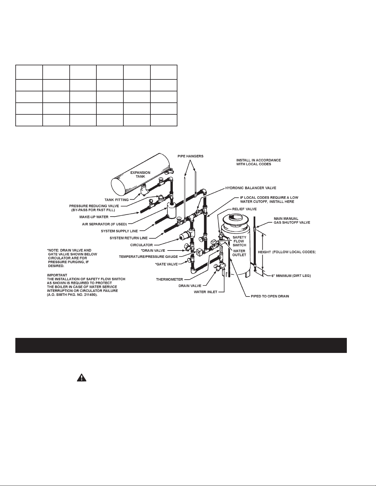
SYSTEM CONNECTIONS
The system installatio n must conform to these instructions
and to the requirements of the local code authority having
jurisdiction. Good practice requires that all heavy piping be
supported.
A TYPICAL BOILER INSTALLATION
FIGURE 7.
VENTING
VENTING THE BOILER - STANDARD VENTING
WARNING
THE INS T RUCT I ONS IN THIS SE CTIO N ON VEN TING
TH E BOILER M UST BE FOLLOWED TO AVOI D CHOK ED
COM B UST ION OR RECI RCU L AT ION OF FLUE GA SES .
SUCH CONDITIONS CAUSE SOOTING OR RISKS OF FIRE
AND ASPHYXIATION.
TYPE B VENTING MAY BE USED WITH THESE BOILERS. ALL
LOCAL UTILITY REGULATIONS ON VENTING SHOULD BE
FOLLOWED.
For boilers for connection to gas vents or chimneys, vent sizing,
installation and termination shall be in accordance with the
current edition of the National Fuel Gas Code, ANSI Z223.1, or
CAN/CSA B149.1, Installation Codes, or applicable provisions
of the local building codes.
Vent connectors serving appliances vented by natural draft shall
not be connected into any portion of mechanical draft systems
operating under positive pressure.
The minimum distance from adjacent public walkways, adjacent
buildings, openable windows and building openings shall not be
less than those values specif ied in the National Fuel Gas Code,
ANSI Z223.1 and/or CAN/CSA B149.1, Installation Codes;
Stack or chimney must be a minimum height of 12 " (305mm)
above the annual snow fall to prevent blockage.
14
Page 15
Building materials must not come in contact with combustion
products from stack or chimney, due to the degradating properties
of ue products.
Vent connectors serving appliances vented by natural draft shall not
be connected into any portion of mechanical draft systems operating
under positive pressure.
Flue products must have a minimum clearance of 4 feet (1.22m)
horizontally from, and in no case above or below, unless a 4-foot
(1.22m) horizontal distance is maintained, from electric meters, gas
meters, regulators and relief equipment.
CAN/CSA B149.1, Installation Code species a 6 foot horizontal
vent terminal clearance to gas and electric meters and relief devices
(this clearance is specied as 4 feet in the U.S. under the National
Fuel Gas Code, ANSI/Z223.1). Therefore instruction, which species
compliance with the 4 foot clearance, as applies in the U.S. only, and the
CAN/CSA B149.1 Installation Code applies in Canada.
1. DRAFT HOOD
The draft hood furnished with this boiler must be installed without
alteration. Provision must be made if the boiler is installed in conned
space or a small boiler room to accommodate draft hood spillage and
avoid risks described above. The upper air opening called for in the
AIR REQUIREMENTS section of this manual is for this purpose.
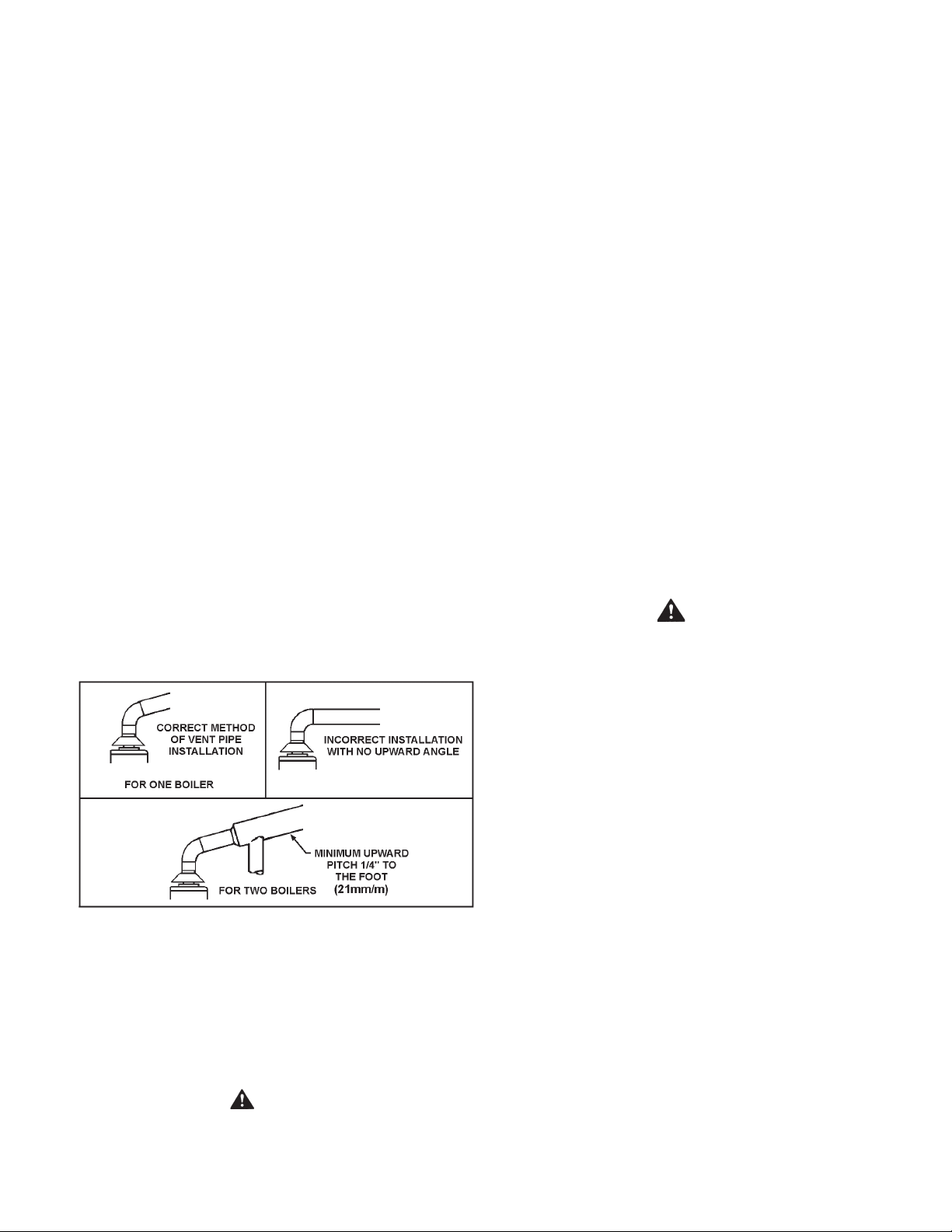
2. VENT CONNECTION
Size and install proper size vent pipe. Do not reduce pipe size to
less than that of the draft hood outlet.
Horizontal runs of vent pipe shall be securely supported by
adequately placed (approximately every 4 feet or 1 meter), noncombustible hanger s and /or slip joints suitable for the weight
and design of the materials employed to prevent sagging and
to maintain a minimum upward slope of 1/4" (21mm/m) per foot
from the boiler to the vent terminals, see Figure 8. Dampers or
other obstructions must not be installed in the vent. Be sure
that the vent pipe does not extend beyond t he inside wall of
the chimney.
3. CONNECTING BOILER TO A COMMON VENT
Do not connect the boiler to a common vent or chimney with solid
fuel burning equipment. This practice is prohibited by many local
building codes as is the practice of venting gas red equipment to
the duct work of ventilation systems.
Where a separate vent connection is not available and the vent pipe
from the boiler must be connected to a common vent with oil burning
equipment, the vent pipe should enter the common vent or chimney
at a point ABOVE the ue pipe from the oil red unit.
Where two or more appliances vent into a common vent connector
or manifold, the area of the common vent or vent connector should
at least equal the area of the largest vent connector plus 50% of the
areas of the additional draft hood outlets.
When removing a boiler from a system with a common vent, use
the following steps:
Be sure the other appliances connected to the common vent are
not in operation.
Seal any unused openings in the common venting system.
Visually inspect the venting system for proper size and horizontal pitch
and determine there is no blockage or restriction, leakage, corrosion
and other deciencies which could cause an unsafe condition.
WARNING
Ensure sufcient supply and ventilation air. Under no circumstances
should the equipment room where the boiler is installed ever be under
negative pressure. Insufcient air supply can interfere with combustion
and ventilation of this boiler resulting in unsafe conditions.
VENT PIPE INSTALLATION
FIGURE 8.
Where a continuous or intermittent back draft is found to exist the
cause must be determined and corrected. A special vent cap may
be required. If the back draft cannot be corrected by the normal
methods or if a suitable draft cannot be obtained, a blower type
ue gas exhauster may be employed to ensure proper venting and
correct combustion if permitted by local codes.
WARNING
FAIL URE TO CORRECT BACK DRAFTS WILL CAUSE AIR
CONTAMINATION AND UNSAFE CONDITIONS.
Insofar as is practical, close all building doors and windows and
all doors between the space in which the appliances remaining
connected to the common venting system are located and other
spaces of the building. Turn on clothes dryers and any appliance not
connected to the common venting system. Turn on any exhaust fans,
such as range hoods and bathroom exhausts, so they will operate
at maximum speed. Close replace dampers.
Place in operation the appliance being inspected. Follow the
lighting instructions. Adjust thermostat so appliance will operate
continuously.
Test for spillage at the draft hood relief opening after ve minutes of
main burner operation. Use the ame of a match or candle.
After it has been determined that each appliance remaining connected
to the common venting system properly vents when tested as outlined
above, return doors, windows, exhaust fans, replace dampers and
any other gas burning appliance to their previous conditions of use.
Any improper operation of the common venting system should be
corrected so the installation conforms with the current edition of
CAN/CSA B149.1 (current edition). When resizing any portion of
the common venting system, the common venting system should
be resized to approach the minimum size as determined using the
appropriate tables in CAN/CSA B149.1.
15
Page 16
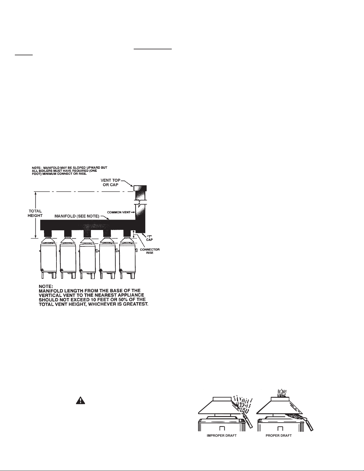
4. MULTIPLE VENT TABLE
Table 5 on page 17 has been compiled to show the material
sizes in a Type B doublewall combined vent system. Refer to
CAN/CSA B149 .1 (current edition), or the ASHRAE 1983 Equipment
Volume for further information.
A combined vent system is one in which two or more boilers at one
level are attached to a common vent.
In order to use table 5, the connector rise and total vent height must
be known. Connector rise is vertical distance from the draft hood outlet
to the point where the manifold connection is made. Total vent height
is the least vertical distance from a draft hood outlet to the top of the
vent. Local codes or utility requirements often govern termination
height. ULC listed doublewall gas vents, up through 24" (610mm)
diameter, can be installed in heated and unheated areas and can
pass through oors, ceilings, partitions, walls and roofs, provided
the required one inch clearance is observed. These vents should be
installed in accordance with CAN/CSA B149.1 (current edition).
EXAMPLE SHOWING USE OF THE HW-610 COMBINED VENT
SIZING TABLE
1. Turn off the electrical power (main manual gas shutoff and pilot
valves, if applicable).
Allow boiler parts and vent to cool before disassembly.
2. Remove the boiler draft diverter and vent pipe running to the chimney.
• Check parts and chimney for obstructions and clean as necessary.
3. Remove burner from boiler and other metal parts as required to
clean and vacuum the heat exchanger and combustion coils.
• Refer to parts list supplied with this manual for disassembly aid.
4. Reinstall the parts removed in steps 2 and 3.
• Be sure the vent pipe has a minimum upward pitch of one quarter
inch per foot of length (21mm/m) and is sealed as necessary.
5. Restore electrical power and gas supply to boiler.
• Place boiler in operation by following the lighting instructions
in this manual.
• Check for gas leaks and proper boiler and vent operation.
VENTING - SIDEWALL (OPTIONAL) POWER VENT SYSTEM
If you are installing the optional Power Vent Kit, refer to your
HW Power Vent Kit Installation Instructions for proper wiring
and installation procedures. Contact your local A. O. Smith
representative for details.
FIGURE 9.
VENTING MAINTENANCE - STANDARD VENTING
It is recommended that the heating surfaces and vent piping of
the appliance be checked every six months for dust, deterioration
and carbon deposits. Remove all soot or other obstructions from
chimney and ue which will retard free draft. Replace any damaged
or deteriorated parts of the venting system.
VENTING SYSTEM
HAVE VENTING SYSTEM CHECKED EVERY SIX MONTHS FOR
OBSTRUCTIONS AND/OR DETERIORATION IN VENT PIPING.
A. Insofar as is practical, close all doors, windows and air inlets to
the building. Turn on all exhaust fans (range hood, bathroom
exhaust, etc.) so they will operate at their maximum speed.
Close replace dampers.
B. After allowing appliance to operate for ve minutes, test for
spillage at the draft hood relief opening.
C. “CHECKING THE DRAFT. Operate vent connected gas utilization
equipment for several minutes and check to see that the combustion
products are going up the chimney or gas vent properly by passing
a lighted match or taper around the edge of the relief opening of
the draft hood. If the chimney or gas vent is drawing properly, the
match ame will be drawn into the draft hood. If not, the combustion
products will tend to extinguish this ame. IF THE COMBUSTION
PRODUCTS ARE ESCAPING FROM THE RELIEF OPENING OF
THE DRAFT HOOD, DO NOT OPERATE THE EQUIPMENT UNTIL
PROPER ADJUSTMENT OR REPAIRS ARE MADE TO PROVIDE
ADEQUATE DRAFT THROUGH THE CHIMNEY OR GAS VENT.”
D. Next, turn on all other fuel burning appliances within the same
room so they will operate at their full input.
Qualied servicers should follow this procedure when the boiler’s
external heating surfaces and vent pipe need cleaning.
CAUTION
DO NOT USE A NYLON BRUSH OR OTHER STATIC CREATING
MATERIAL TO CLEAN DUST AND CARBON DEPOSITS FROM
HEATING SURFACES AND VENT.
SUCH DEPOSITS ARE FLAMMABLE AND MAY BE IGNITED BY
STATIC ELECTRICITY. USE A METAL BRUSH TO MINIMIZE THE
DANGER OF EXPLOSION.
Repeat step C above, checking the draft on each appliance.
FIGURE 10.
16
Page 17
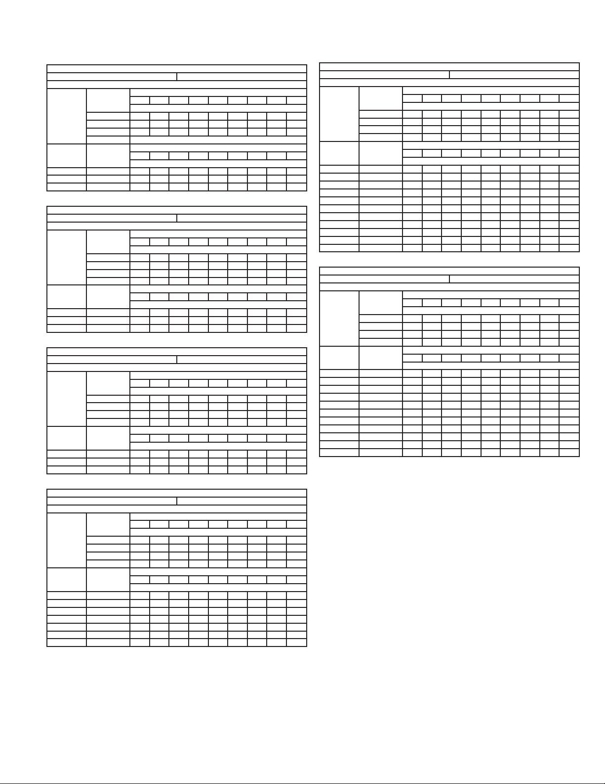
TABLE 5, COMBINED VENT SIZING TABLES
Input: 300,000 Btuh Draft Hood Outlet 8"
Connector
Rise in Feet
1 10 10 10 10 10 10 10 10 10
2 10 10 10 10 10 10 10 10 10
3 10 10 10 10 10 10 10 10 10
Number
if Units
Combined
2 600 14 12 12 12 10 10 10 10 10
3 900 16 14 14 14 12 12 12 12 12
4 1200 18 16 16 14 14 14 14 12 12
Number
if Units
Combined
2 798 14 14 14 12 12 12 12 12 12
3 1197 18 16 16 14 14 14 14 14 12
4 1596 20 20 18 16 16 16 14 14 14
Number
if Units
Combined
2 840 14 14 14 12 12 12 12 12 12
3 1260 18 16 16 14 14 14 14 14 12
4 1680 20 20 18 16 16 16 14 14 14
4 or more
Total Input
Btuh x 1000
Input: 399,000 Btuh Draft Hood Outlet 10"
Connector
Rise in Feet
1 12 12 12 12 12 12 12 12 12
2 12 12 12 10 10 10 10 10 10
3 12 10 10 10 10 10 10 10 10
4 or more 10 10 10 10 10 10 10 10 10
Total Input
Btuh x 1000
Input: 420,000 Btuh Draft Hood Outlet 10"
Connector
Rise in Feet
1 12 12 12 12 12 12 12 12 12
2 12 12 12 10 10 10 10 10 10
3 12 10 10 10 10 10 10 10 10
4 or more 10 10 10 10 10 10 10 10 10
Total Input
Btuh x 1000
MODEL HW-300 BOILER
Required Connector or Smoke Pipe Diameter
Total Vent Height (Measured in Feet Above Draft Hood)
10 15 20 30 40 50 60 80 100
Total Vent Height (Measured in Feet Above Draft Hood)
10 15 20 30 40 50 60 80 100
MODEL HW-399 BOILER
Required Connector or Smoke Pipe Diameter
Total Vent Height (Measured in Feet Above Draft Hood)
10 15 20 30 40 50 60 80 100
Total Vent Height (Measured in Feet Above Draft Hood)
10 15 20 30 40 50 60 80 100
MODEL HW-420 BOILER
Required Connector or Smoke Pipe Diameter
Total Vent Height (Measured in Feet Above Draft Hood)
10 15 20 30 40 50 60 80 100
Total Vent Height (Measured in Feet Above Draft Hood)
10 15 20 30 40 50 60 80 100
Connector Diameter (in Inches)
Manifold and Common Vent Diameter (in Inches)
Connector Diameter (in Inches)
Manifold and Common Vent Diameter (in Inches)
Connector Diameter (in Inches)
Manifold and Common Vent Diameter (in Inches)
Input: 610,000 Btuh Draft Hood Outlet 12"
Connector
Rise in Feet
1 16 14 14 14 14 14 14 14 14
2 14 14 14 14 14 12 12 12 12
3 14 14 12 12 12 12 12 12 12
Number
if Units
Combined
2 1220 18 18 16 16 14 14 14 14 14
3 1830 22 20 20 18 18 16 16 16 14
4 2440 26 24 22 20 20 18 18 18 16
5 3050 28 26 26 24 22 22 20 20 18
6 3660 32 28 28 26 24 24 22 22 20
7 4270 34 32 30 28 26 24 24 22 22
8 4880 36 34 32 30 28 26 26 24 24
9 5490 38 36 34 30 30 28 28 26 24
10 6100 40 38 36 32 30 30 28 26 26
11 6710 42 38 38 34 32 30 28 28 26
12 7320 44 42 38 36 34 32 32 30 28
Number
if Units
Combined
2 1220 18 18 16 16 14 14 14 14 14
3 1830 22 20 20 18 18 16 16 16 14
4 2440 26 24 22 20 20 18 18 18 16
5 3050 28 26 26 24 22 22 20 20 18
6 3660 32 28 28 26 24 24 22 22 20
7 4270 34 32 30 28 26 24 24 22 22
8 4880 36 34 32 30 28 26 26 24 24
9 5490 38 36 34 30 30 28 28 26 24
10 6100 40 38 36 32 30 30 28 26 26
11 6710 42 38 38 34 32 30 28 28 26
12 7320 46 44 40 38 36 34 34 32 30
4 or more 12 12 12 12 12 12 12 12 12
Total Input
Btuh x 1000
Input: 660,000 or 670,000 Btuh Draft Hood Outlet 12"
Connector
Rise in Feet
1 16 14 14 14 14 14 14 14 14
2 14 14 14 14 14 12 12 12 12
3 14 14 12 12 12 12 12 12 12
4 or more 12 12 12 12 12 12 12 12 12
Total Input
Btuh x 1000
MODEL HW-610 BOILER
Required Connector or Smoke Pipe Diameter
Total Vent Height (Measured in Feet Above Draft Hood)
10 15 20 30 40 50 60 80 100
Total Vent Height (Measured in Feet Above Draft Hood)
10 15 20 30 40 50 60 80 100
MODEL HW-670 BOILER
Required Connector or Smoke Pipe Diameter
Total Vent Height (Measured in Feet Above Draft Hood)
10 15 20 30 40 50 60 80 100
Total Vent Height (Measured in Feet Above Draft Hood)
10 15 20 30 40 50 60 80 100
Connector Diameter (in Inches)
Manifold and Common Vent Diameter (in Inches)
Connector Diameter (in Inches)
Manifold and Common Vent Diameter (in Inches)
Input: 520,000 Btuh Draft Hood Outlet 10"
Connector
Rise in Feet
1 14 14 14 12 12 12 12 12 12
2 12 12 12 12 12 12 12 12 12
3 12 12 12 12 10 10 10 10 10
Number
if Units
Combined
2 1040 16 16 14 14 14 14 12 12 12
3 1560 20 18 18 16 16 14 14 14 14
4 2080 22 22 20 18 18 18 16 16 14
5 2600 26 24 22 20 20 18 18 18 18
6 3120 28 26 24 22 22 20 20 18 18
7 3640 30 28 26 24 24 22 22 20 20
8 4160 32 30 28 26 24 24 22 22 20
4 or more 12 12 12 12 10 10 10 10 10
Total Input
Btuh x 1000
MODEL HW-520 BOILER
Required Connector or Smoke Pipe Diameter
Total Vent Height (Measured in Feet Above Draft Hood)
10 15 20 30 40 50 60 80 100
Total Vent Height (Measured in Feet Above Draft Hood)
10 15 20 30 40 50 60 80 100
Connector Diameter (in Inches)
Manifold and Common Vent Diameter (in Inches)
Known: (5) model HW-610 boilers. (See illustration).
Connector rise - 2' (Note 1' is minimum). Total vent
height 30'.
Problem: Determine diameter of connector, manifold and
common vent.
Procedure: Enter the top of the HW-610 table (total vent height)
at 30' and the side at 2' (connector rise). A 14"
connector diameter is indicated for each connector
rise.
To determine the manifold and common vent size, enter table on this
page (total vent height) at 30 and the side at 5 boilers. A manifold
diameter of 24" (610 mm) is indicated.
17
Page 18

SYSTEM INSTALLATIONS
1. CONVENTIONAL INSTALLATIONS
All modern hydronic type boilers are exceptionally fast heating units.
The low water volumes in relation to ring rates require special
attention to water ow rates for smooth, efcient operation. These
considerations for the A. O. Smith copper heat exchanger boilers
are covered below.
Conventional 20
0
F (100C) drop in systems for a fully loaded boiler
will maintain the following approximate ow rates:
MODELS GPM (LPM)
HW-300 23 (87)
HW-399 30 (114)
HW-420 35 (132)
HW-520 39 (148)
HW-610/670 46 (175)
Figure 7 on page 14 shows a typical installation of the boiler with pipe
sizing and circulator selected by the installer to provide adequate
water ow whenever the boiler is ring.
In a system with several large zones of which any might be smaller
than approximately 1/3 of the system should include a hydronic
balancer as shown in Figure 7. The balancer connects between
the system supply and the return line before the circulator inlet.
Adjustment of the balancing cock should permit adequate boiler ow
rate when only the smallest zone is in operation.
Attention should be given to balancing inputs and water ow rates
where wide variations of system ow rates can occur.
The recommended minimum ow rates that will result in approximately
0
F (300C) temperature rise across the boiler are as follows:
50
ONE BOILER INSTALLED
INDEPENDENT OF THE PRIMARY SYSTEM
FIGURE 11.
Total heating requirements for the building can be supplied by a
series of boiler loops all connecting to a common pipe joining the
system supply and return mains. The supply and return branches of
each boiler loop must join the common pipe only a short nipple length
apart. The different sets of branches should be installed reasonably
close together, but not necessarily to the short nipple length as
required for the supply and return of each set. These branches may
be made with tees or with welded connections.
The installer is reminded that the total boiler ow rates need not
match the system ow rate.
MODELS GPM (LPM)
HW-300 9 (34)
HW-399 12 (45)
HW-420 14 (53)
HW-520 16 (61)
HW-610 18 (69)
HW-670 20 (76)
If system ow rate is unknown, or if zoning creates extreme variations
in ow rates, the boiler should be installed as shown in Figure 11 on
this page for A. O. Smith LINEAR-TEMP installations.
2. LINEAR-TEMP INSTALLATIONS
A. New Installations
A. O. Smith LINEAR-TEMP systems have been designed to provide
efcient, trouble-free operation of the boiler sizes covered in this
manual with any of the following conditions:
a. Unknown system ow rate
b. Varying ow rate as with zoned systems
c. Multiple boiler installations
Figure 11 on this page shows piping and accessory arrangement
for a boiler pumped independent of the primary system mains. Pipe
sizing and boiler loop pump selection data are shown in Table 6 for
several different temperature rises across the boilers.
TABLE 6.
PUMP AND PIPE SIZING DATA
(PIPING FROM TEES IN MAIN TO BOILER BRANCHES)
Model Temp. Rise °F (°C) G.P.M. *Pump Size Pipe Size
1-1/2" PR
20 (10)
HW-300
HW-399
HW-420
HW-520
HW-610/670
NOTE: Pipe loop sizes and pump selections based on
50 equivalent feet of pipe and ttings.
*All pump sizes listed are B & G model numbers.
30 (15)
30 (15)
40 (20)
20 (10)
35 (15)
40 (20)
40 (20)
20 (10)
35 (15)
40 (20)
40 (20)
20 (10)
20 (10)
35 (17)
40 (20)
20 (10)
30 (15)
35 (17)
40 (20)
23
15
15
11
30
20
15
15
32
21
16
16
39
26
23
20
51
34
29
25
150
125
100
60-13
1-1/2" HV
150
125
60-13
1-1/2" HV
150
125
2-1/2"
1-1/2" HV
1-1/2" HV
150
60-13
2-1/2"
2"
1-1/2" HV
2"
1-1/2"
1-1/4"
1"
2"
1-1/2"
1-1/2"
1-1/4"
2"
1-1/2"
1-1/2"
1-1/4"
2-1/2"
2"
1-1/2"
1-1/2"
3"
2-1/2"
2"
1-1/2"
18
Page 19

NO. SUGGESTED ITEMS FOR INSTALLATION
Short pipe nipple and pair of boiler loop tees in piping
1
between system supply and return. One set per each group
of boilers.
2 Boiler pipe loop. See piping sizing data.
3 Boiler circulator. See pump sizing data.
4 Thermometer.
5 Theraltimeter.
6 Plug cock to control ow rate.
Safety ow switches. For interlock with other systems or
7
instead of low water cutoff.
8 Relief valve.
With one -300, -399 or -420 item 9 is - sensing element of
remote control.
With a group of -300's, -399's or -420's, item 9 is - for 1st
9
boiler, the sensing element as above. For additional boilers,
install a 2nd limit control if required by local codes. With
any -520, -610 or 670 boilers, install 2nd limit control here if
required by local code.
BOILER INLET - OUTLET SIZES
HW-300 - 1-1/4", HW-399 - 1-1/2", HW-420 - 1-1/2",
10
HW-520 & HW-610 - 2".
HW-300 - 1-1/4", HW-399 - 1-1/2", HW-420 - 1-1/2", HW-520
10
& HW-670 - 2".
MINIMUM BRANCH SIZES TO BOILERS
HW-300 - 1-1/4" HW-520, 610 (Single boiler
11
HW-399 - 1-1/2" per pump) 2"
HW-420 - 1-1/2"
HW-300 - 1-1/4" HW-520, 670 (Single boiler
11
HW-399 - 1-1/2" per pump) 2"
HW-420 - 1-1/2"
Flow control valve. Required only if ow rate of system
12
primary is excessive for size of boiler branch tees or if chilled
water main is above boilers.
13 System supply temperature thermometer.
Boiler headers for three (3) boilers can be larger than pipe
14
loop, if desired, to aid in balancing.
The system flow rate is selected to give the desired system
temperature drop - depending on the design criteria.
The boiler generator ow rates, on the other hand, should be
selected to give the temperature rise through the generator that is
both economical and offers the best generator efciency.
The boiler temperature rise is normally between 10
0
C and 200C (200F
and 400F). The system temperature that will be introduced to the
boiler (inlet temperature) plus the selected boiler temperature rise
selected from PUMP AND PIPE SIZING DATA should not exceed
the high limit control setting of 1150C (2400F).
SCHEMATIC OF THE LINEAR-TEMP® SYSTEM
FIGURE 12.
Supply and return headers of the old system should be connected
to the boiler loop with a pair of tees set close together. The boiler
loop pump and the boiler(s) should be wired to operate only when
any of the system pumps are in operation. The number of zone
pumps that may be in operation at any particular time will take
their required ow rate out from the rst tee in the boiler piping.
This water will be circulated through the proper branches from
the supply header to the zones calling for heat. The water will be
brought back to the return header and then into the second tee in
the boiler pipe loop. There will be no conict between the boiler
pump and the zone pumps when the two tees in the boiler loop
are placed close together.
Normal use of ow control valves is required to prevent cross
circulation of zones as with any multiple pump system. Flow control
is not required on boiler circuit.
Attention should be given to balancing gas inputs and water ow
rates. Large systems with multiple boilers should include main water
temperature control (with or without outdoor reset) to stage the boilers
on and off in relation to the load on the system.
3. WATER SUPPLY LINE
These boilers can be used ONLY in a forced circulation hot water
heating system. Since most forced circulation systems will be of
the closed type, install the water supply line as shown on piping
diagrams, Figure 7 to 11 on pages 14 and 18.
Fast lling of large pipe, old radiator installations and pressure
purging of series loop systems (where high pressures are not
available) requires bypassing of the pressure reducing valve.
Generally, pressure purging is not possible with a well pump system.
High point air venting is essential.
If the system is of the open type, a pressure reducing valve
will not be required as the water supply to the system will be
controlled by a manually operated valve. An overhead surge
tank is required.
There should be a relation of the minimum system load to the size
boiler selected as the rst ring or base boiler. This will stabilize
operation during minimum load periods.
B. Commercial Boiler Replacements
®
Application of LINEAR-TEMP
to a commercial boiler replacement
with an old multiple pump installation is an excellent way to modernize
the system. The A. O. Smith boiler(s) should be installed on a pipe
loop with a separate circulating pump selected from PUMP AND
PIPE SIZING DATA TABLE.
Figure 12 shows a line drawing of how the system headers should be
connected to the pipe loop installed with the replacement boiler(s).
Make-up water connections and accessories are not shown.
4. EXPANSION TANK
CAUTION
A closed system will exist if a check valve (without bypass), pressure
reducing valve (without bypass), or a water meter (without bypass) is
installed in the cold water line between the water heater and street
main (or well).
Excessive pressure may develop causing premature tank failure or
intermittent relief valve operation. This is not a warranty failure. An
expansion tank or a similar device may be required in the inlet supply
line between the appliance and the meter or valve to compensate for
the thermal expansion of water under supply pressure, see Figure 7
on page 14.
An air separator as shown in the piping diagrams is recommended
especially for modern commercial hydronic systems.
19
Page 20

5. VENT VALVES
It is recommended that automatic, loose key or screwdriver type
vent valves be installed at each convector or radiator.
6. MANIFOLD HEADERS
Split systems with individual supply and return lines from the boiler
room should normally have this piping connected to supply and
return manifold headers near the boiler. To achieve good water
distribution with maximum pressure drop for several circuits,
manifolds of at least 2-1/2" (64mm) diameter are suggested on
HW-399, HW-420, HW-520, HW-610 and HW-670 units. HW-300
units should have 1-1/2" (38mm) diameter manifolds.
The circuits should be spaced on the header at a minimum of
3" (76mm) center to center. Install a balancing cock in each return line.
Manifold headers are recommended for split systems with or without
zone valves and also those installations with zone circulators. If the
system is to be split at remote points, good practice requires special
attention be given to main pipe sizing to allow balancing of water ow.
The boiler piping system of a hot water boiler connected to heating
coils located in air handling units where they may be exposed to
refrigerated air circulation must be equipped with ow control valves or
other automatic means to prevent gravity circulation of the boiler water
during the cooling cycle.
7. COOLING PIPING
When the boiler is used in conjunction with a refrigeration system it
must be installed so that the chilled medium is piped in parallel with
the boiler with appropriate valves to prevent the chilled medium from
entering the boiler, see Figure 13.
Water temperature in the heating system must be reduced to less
than 100
the chiller unit may occur.
0
F (38°C) before cooling system is started, or damage to
If the boiler is connected to chilled water piping or its heating coils
are exposed to refrigerated air, the boiler piping system must be
equipped with ow valves or other automatic means to prevent gravity
circulation through the boiler during the cooling cycle.
8. CIRCULATING PUMP
CONSTANT CIRCULATING PUMP OPERATION OF THE BOILER
VOIDS THE WARRANTY. Constant water ow through the unit
will “wash” away the copper’s natural protective coating. This is
called velocity erosion. This erosion is not as great a problem when
intermittent circulating operation is used per the recommended
installation procedure. Constant circulation of water through the
building’s system main is permissible as long as the water does not
constantly ow through the boiler. Only all bronze or stainless steel
circulators are to be used with the unit when it is installed in HOT
WATER SUPPLY SYSTEMS.
A TYPICAL CIRCULATING PUMP
FIGURE 14.
Although each circulator that requires oiling is oiled and operated by
the manufacturer, IT MUST BE OILED AGAIN BEFORE OPERATED.
Oil the three oil cups (2 on the motor, 1 on the pump) as instructed
on the oil tube supplied with the unit, see Figure 14 on this page.
SCHEMATIC SHOWING PROPER PIPING ISOLATION
OF THE BOILER FROM THE CHILLER
FIGURE 13.
GAS CONNECTIONS
WARNING
THIS BOILER IS NOT INTENDED TO OPERATE AT GAS SUPPLY
PRESSURE OTHER THAN SHOWN ON THE RATING PLATE.
EXPOSURE TO HIGHER GAS SUPPLY PRESSURE MAY CAUSE
DAMAGE TO GAS VALVES WHICH CAN RESULT IN FIRE OR
EXPLOSION. IF OVERPRESSURE HAS OCCURRED SUCH AS
THROUGH IMPROPER TESTING OF GAS LINES OR EMERGENCY
MALFUNCTION OF THE SUPPLY SYSTEM, THE GAS VALVES MUST BE
CHECKED FOR SAFE OPERATION. MAKE SURE THAT THE OUTSIDE
VENTS ON THE SUPPLY REGULATORS AND THE SAFETY VENT
VALVES ARE PROTECTED AGAINST BLOCKAGE. THESE ARE PARTS
OF THE GAS SUPPLY SYSTEM, NOT THE BOILER. VENT BLOCKAGE
MAY OCCUR DURING ICE BUILD-UP OR SNOW STORMS.
Thereafter, during the heating season, lubricate the three oil cups at
least once every four months. Combination heating-cooling systems
should be lubricated every four months year ‘round.
Use 2 or 3 teaspoonsful in bearing oil cups or 12 drops in the motor
oil cups, see Figure 14 on this page. Use No. 20 non-detergent
motor oil.
Follow the same oiling procedure if a replacement circulator is
installed into the system.
WHEN LOCAL CODES REQUIRE A MAIN MANUAL SHUTOFF
VALVE OUTSIDE THE BOILER JACKET, A SUITABLE MAIN
MANUAL SHUTOFF VALVE MUST BE INSTALLED IN A LOCATION
COMPLYING WITH THOSE CODES.
IT IS IMPORTANT TO GUARD AGAINST GAS VALVE FOULING
FROM CONTAMINANTS IN THE GAS WAYS. SUCH FOULING
MAY CAUSE IMPROPER OPERATION, FIRE OR EXPLOSION.
IF COPPE R SUPP LY LINES ARE USE D THEY MUST BE
CERTIFIED FOR GAS SERVICE.
BEFORE ATTACHING THE GAS LINE BE SURE THAT ALL GAS
PIPE IS CLEAN ON THE INSIDE.
20
Page 21

TO TR AP ANY DIRT OR FO REIGN M ATERIAL IN THE GAS
SU PPLY LIN E, A D IRT LEG (SOME TI MES CALLED D RIP
LEG or sediment trap) MUST BE INCORPOR ATED I N THE
PIPING, see Figure 1 on page 6. The dirt leg must be readily
accessible and not subject to freezing conditions. INSTALL IN
ACCORDANCE WITH RECOMMENDATIONS OF SERVING
GAS SUPPLIERS. (Refer to National Fuel Gas Code, ANSI
Z2 23.1 or CAN/CSA -B 149.1 Installation Co des.
To preve nt dam age, care mus t b e ta ken not to a pp ly too
much torque when attaching gas supply pipe to the gas valve
gas inlet.
Use table 7, o r CAN / C S A B1 4 9 .1 (c ur r e n t e d i t i o n) to
size ir o n pipe or e q u i valent ga s supply li n e . Ta b l e 7
is base d o n a pres sur e d rop of 0. 3 inch es of water an d
a speci f i c grav i t y of 0.60 app r oxi mate ly that of na tura l
gas. (LP gas has an S.G. of about 1.53). If the ser vice pressure
is five inches water column or less, use one pipe size larger in
order to minimize pressure drop in the line.
TABLE 7.
MAXIMUM CAPACITY OF PIPE IN CUBIC FEET OF GAS PER
HOUR (BASED UPON A PRESSURE DROP OF 0.3 INCH
WATER COLUMN AND 0.6 SPECIFIC GRAVITY GAS)
Fi tti ngs and uni ons in th e g as line must be th e m eta l to
metal type.
Apply joint compounds (pipe dope) sparingly and only to the
male threads of pipe joints. Do not apply compound to the first
two threads. Use compounds resistant to the action of liquefied
petroleum gases.
THE BOILER AN D ITS GAS CONNECTIONS MUST BE LEAK
TESTED BEFORE PLACING THE BOILER IN OPERATION.
Use soap and water solution or other material acceptable for
the pur pose in locating gas leaks. DO NOT USE MATCHES,
CANDLES, FL AME OR OTHER SOURCES OF IGNITION FOR
THIS PURPOSE.
DISCONNECT THE BOILER AND ITS MAIN MANUAL
GAS SHU TOFF VA LVE FROM THE G AS SUPPLY PIPING
SYSTEM DURING ANY PRESSURE TESTING OF THE GAS
SUPPLY SYSTEM OVER 1/2 PSIG (3.5kPa). THE GAS SUPPLY
LI N E MUST BE CAPP ED WHE N NOT CO N NEC TED TO
THE BOILER.
THE BOILER MUST BE ISOLATED FROM THE GAS SUPPLY
PI PI NG SYSTEM BY CLOSING ITS MAIN MANUAL GAS
SHUTOFF VALVE DURING ANY PRESSURE TESTING OF
THE GAS SUPPLY PIPING SYSTEM AT TEST PRESSURES
EQUAL TO OR LESS THAN 1/2 PSIG (3.5kPa).
PURGING AND SIZING
Distance
from Gas
Meter
10 (3) 132 278 520 1,050 1,600 3,050 4,800 8,500 17,500
20 (6) 92 190 350 730 1,100 2,100 3,300 5,900 12,000
30 (9) 73 152 285 590 890 1,650 2,700 4,700 9,700
40(12) 63 130 245 500 760 1,450 2,300 4,100 8,300
50 (15) 56 115 215 440 670 1,270 2,000 3,600 7,400
60 (18) 50 105 195 400 610 1,150 1,850 3,250 6,800
70 (21) 46 96 180 370 560 1,050 1,700 3,000 6,200
80 (24) 43 90 170 350 530 990 1,600 2,800 5,800
90 (27) 40 84 160 320 490 930 1,500 2,600 5,400
100 (30) 38 79 150 305 460 870 1,400 2,500 5,100
125 (38) 34 72 130 275 410 780 1,250 2,200 4,500
150 (45) 31 64 120 250 380 710 1,130 2,000 4,100
175 (53) 28 59 110 225 350 650 1,050 1,850 3,800
200 (60) 26 55 100 210 320 610 980 1,700 3,500
*The heating value of Natural Gas is approximately 1,050 Btu/Ft.3.
Propane (LP) Gas has a heating value of approximately 2,500 Btu/Ft
1 cu. meter=35.31 cu. feet.
1/2 3/4 1 1 1/4 1 1/2 2 2 1/2 3 4
Nominal Iron Pipe Size (Inches)
3
.
Where it is necessary to use more than the average number of pipe
ttings i.e. elbows, tees, and valves in gas supply line, use a pipe
larger than specied to compensate for increased pressure drop.
2B. SIZING GAS SUPPLY LINE (For multiples of over three boilers of
same size or for multiple installations of two or more mixed sizes).
Gas line purging is required with new piping or systems in which
air has entered.
CAUTION
PURGING S H O U L D B E PERFORMED B Y PERSONS
EXPERIENCED IN THIS TYPE GAS SERVICE TO AVOID RISK OF
FIRE OR EXPLOSION. PURGE DISCHARGE MUST NOT ENTER
CONFINED AREAS OR SPACES WHERE IGNITION CAN OCCUR.
THE AREA MUST BE WELL VENTILATED AND ALL SOURCES OF
IGNITION MUST BE INACTIVATED OR REMOVED.
1. CORRECT GAS
Make sure the gas on which the boiler will operate is the same as
that specied on the boiler rating plate. Do not install the boiler if
equipped for a different type gas — consult your supplier.
2A. SIZING GAS SUPPLY LINE (For single boiler installations
and for installations of multiples of two or three of same
size boilers).
Capacities in cubic feet per hour of 0.60 specic gravity gas for
different sizes and lengths are shown in table 7. No additional
allowance is necessary for an ordinary number of ttings.
Applications of the gravity factor converts the gures given in table
7 to capacities with another gas of different specic gravity. Such
application is accomplished by multiplying the capacities given in
table 7 by the multipliers shown in table 8 on page 22.
To determine the size of each section of gas piping in a system within
the range of table 7 proceed as follows:
• Determine the gas demand of each appliance to be attached
to the piping system. When table 7 is to be used to select the
piping size, calculate the gas demand in terms of cubic feet
per hour for each piping system outlet. The gas demand for
an appliance can be found by dividing its heat input rate by
the gas’s heating value.
• Obtain or determine the length of piping from the gas meter or
service regulator to the appliance(s).
21
Page 22

• In table 7 on page 21, select the row showing the distance to
GROUND
TERMINALS (2)
PILOT
OUTLET
GAS
CONTROL
PILOT ADJUSTMENT
(UNDER CAP SCREW)
PILOT SUPPLY
OUTLET
INLET
GAS VALVE KNOB
PRESSURE REGULATOR
ADJUSTMENT
PILOT ADJUSTMENT
UNDER SCREW
the most remote outlet or the next longer distance if the table
does not give the exact length. This is the only distance used in
determining the size of any section of gas piping. If the gravity
factor is to be applied, the values in the selected row of table 7
are multiplied by the appropriate multiplier from table 8.
• Total the gas demands of all appliances on the piping system.
Enter table 7, on the left hand side, at the row equal to or just
exceeding the distance to the most remote outlet. Select the
pipe size in the row with a capacity equal to or just exceeding
the total gas demand. This is the required main gas supply line
size leading away from the gas meter or regulator. To determine
the pipe size required for each branch outlet leading away from
the main supply line, determine the gas demand for that outlet.
Enter table 7 on the same row, and select the branch pipe
size for a capacity equal to or just exceeding the demand at
that outlet. The main line can be resized for a lesser capacity
after each branch outlet, since the gas demand is reduced.
Total the gas demands of all remaining appliances branching
off downstream on the main gas line. Re-enter table 8 in the
same row and select the appropriate pipe size with adequate
capacity. Repeat the branch sizing and main line re-sizing for
any remaining appliances in the system.
TABLE 8.
MULTIPLIERS TO BE USED WITH TABLE 7 WHEN APPLYING
THE GRAVITY FACTOR TO OTHER THAN .60 SPECIFIC GRAVITY
Specic
Gravity
Multiplier
Specic
Gravity
Multiplier
.35 1.31 1.00 .78
.40 1.23 1.10 .74
.45 1.16 1.20 .71
.50 1.10 1.30 .68
.55 1.04 1.40 .66
*.60 (Nat.) 1.00 *1.50 (Prop.) .63
.65 .96 1.60 .61
.70 .93 1.70 .59
.75 .90 1.80 .58
.80 .87 1.90 .56
.85 .84 *2.00 (Butane) .55
.90 .82 2.10 .54
*Use these correction factors if exact specic gravity of the gas is not known.
GAS PRESSURE REGULATORS
The gas pressure regulator is included in the combination gas valve,
Figure 15, and is set to operate on the gas specied on the boiler
model and rating plate.
EXAMPLE
Job Condition:
Determining the required gas pipe size for a system composed of two
HW-420 boilers and two HW-610 boilers to be installed as a multiple
group, 50 lineal feet from meter. Gas to be used has a .60 specic
gravity and heating value of 1,000 Btu per cubic foot.
Solution:
2 HW-420 Boilers = 840,000 Btuh
2 HW-610 Boilers = 1,220,000 Btuh
Total Btuh Input = 2,060,000 Btuh
Total Btuh Input = 2,060,000 Btuh = 2,060 cf/h
Btu per Cubic Foot of Gas 1,000
With a cubic foot per hour demand of 2,060 and with 50 lineal
feet of gas supply line, table 7 shows a pipe size of 3" (76mm)
is required.
NOTE: For other than .60 specic gravity, apply multiplier factor as
shown in table 8.
FIGURE 15.
Periodically check main burner, Figure 34 on page 39, and pilot
flame, Figure 35 on page 40, for proper operation. This should
be checked every six months.
Do not subject the gas valve to inlet gas pressures of more than 14"
W.C. (1/2 P.S.I.). If higher gas pressures are encountered, a service
regulator is necessary.
TABLE 9.
CORRECT MANIFOLD PRESSURE FOR FULL
BOILER INPUT (IN INCHES OF WATER COLUMN)
Model
Number
Rated
Input
Manifold Pressure
Natural Propane
HW-300 300,000 3.5 10.0
HW-399 399,000 3.2 9.5
HW-420 420,000 3.5 10.0
HW-520 520,000 3.5 10.0
HW-610 610,000 3.5 10.0
HW-670 Nat. 660,000 3.5
HW-670 Prop. 670,000 10.0
22
Page 23

Adjustment, if required, is performed as follows:
1. Set primary system temperature control dial (thermostat) at
lowest setting so that boiler will not call for heat.
2. Attach a pressure gauge to the tapping in the control string
elbow.
3. Reset primary system temperature control dial (thermostat) to
highest setting. Main burner will now ignite.
4. With main burner ring, adjust pressure, if necessary, by turning
pressure regulator adjusting screw with a screwdriver.
• Clockwise to increase pressure.
• Counterclockwise to decrease pressure.
WIRING
5. Set primary system temperature control dial (thermostat) to
lowest setting.
6. Remove pressure gauge and replace sealing plug.
7. Set primary system temperature control dial (thermostat) to
desired setting.
WARNING
DO NOT INCREASE GAS PRESSURE ABOVE THAT SPECIFIED
ON THE RATING PLATE, AS OVERFIRING WILL RESULT IN
DAMAGE TO THE BOILER, AS WELL AS INCREA SE D R IS K
OF FIRE, SOOTING AND ASPHYXIATION.
If gas pressure regulator cannot be adjusted to correct pressure with
sufcient gas pressure at the valve, replace with new gas valve.
WIRING CONNECTIONS
CAUTION
LA BEL ALL WI RES PRIOR TO DIS CONNE CTI ON WHEN
SERVICING CONTROLS. WIR IN G ERRORS CAN CAUSE
IMPROPER AND DANGEROUS OPERATION. VERIFY PROPER
OPERATION AFTER SERVICING.
1. CONVENTIONAL INSTALLATIONS
ALL ELECTRICAL WORK MUST BE INSTALLED IN ACCORDANCE
WITH NATIONAL ELECTRICAL CODE, ANSI/NFPA 70 AND/
OR THE CANADIAN ELECTRICAL CODE, PART 1, CSA C22.1,
ELECTRICAL CODE AND MUST CONFORM TO LOCAL
REGULATIONS.
The boiler, when installed, must be electrically bonded to ground in
accordance with the requirements of the authority having jurisdiction
or, in the absence of such requirements, with the National Electrical
Code, ANSI/NFPA 70 and/or the Canadian Electrical Code Part 1,
CSA C22.1, Electrical Code.
STRICT ADHERENCE TO PIPING AND WIRING DIAGRAMS IS
REQUIRED TO PREVENT CONSTANT PUMP OPERATION WHEN
SYSTEM TEMPERATURE CONTROL IS SATISFIED. OTHERWISE
THE WARRANTY IS VOID AS STIPULATED IN THE LIMITED
WARRANTY ON THE INSTRUCTIONS MANUAL.
The electrical connections must be made so that the circulator will
operate before the gas valve opens. At no time may the controlling
system allow the burner to re when there is no water ow through
the boilers.
Refer to the diagrams in Figures 16 and 17 on pages 24 and
25 for proper wiring sequence with conventional single boiler
installations.
The THERMAL BALANCER shown is factory included by
A. O. Smith. This device serves as a pump shutdown delay switch to
balance the rising boiler water temperature to system temperature
before the pump stops. Overshooting of boiler temperature is
prevented and stack loss after shutdown is negligible.
WARNING
AN ELECTRICAL GROUND IS REQUIRED TO REDUCE RISK OF
ELECTRIC SHOCK OR POSSIBLE ELECTROCUTION. Make the
ground connection to the screw provided in the electrical supply
junction box on the boiler.
IF ANY OF THE ORIGINAL WIRE, AS SUPPLIED WITH THE
APPLIANCE, MUST BE REPLACED, IT MUST BE REPLACED
WITH TYPE 105
THE FLAME SENSOR AND IGNITION CABLE WHICH ARE 250
AND WIRES CONNECTED TO THE COIL PROTECTOR WHICH
ARE 200
0
C.
0
C WIRE OR ITS EQUIVALENT, EXCEPT FOR
0
C
23
Page 24

120 VAC 60 HZ
L1 (HOT) L2 (NEUTRAL)
L1 (HOT) L2 (NEUTRAL)
120 VAC 60 HZ
120V
24V
HIGH LIMIT
IGNITION MODULE
CHASSIS
GROUND
IGNITOR WIRE TO
PILOT
NOTE: IF REPLACING ANY FACTORY WIRING, USE
TYPE 105°C WIRE OR EQUIVALENT, EXCEPT FOR
THE IGNITION WIRE WHICH USES 250°C WIRE
AND THE COIL LIMIT WHICH USES 200°C WIRE.
192359-000 Rev. 3
%%UWIRING
BY FACTORY
BY INSTALLER
** THESE COMPONENTS
ARE NOT FACTORY
INSTALLED AND MUST BE
SUPPLIED BY THE
INSTALLER.
GAS VALV E
COIL
LIMIT
GND
4 X 4 JUNCTION BOX
WITH TERMINAL STRIP
WHITE
GAS VALV E
BROWN
IGNITION
MODULE
WHITE
YELLOW
WHITE
RED
MV
MV
PV
PV
24V GND
GND
GND
SPARK
TO
PILOT
24V
MV/PV
MV/PV
MV
PV
MV/PV
THERMAL
BALANCER
THERMAL
BALANCER
** FUSED
DISCONNECT
SWITCH
FUSED
DISCONNECT
SWITCH
** TANK TEMP
PROBE
TANK TEMP
PROBE
WATER PUMP
** SAFETY FLOW
SWITCH (REQUIRED)
SAFETY FLOW
SWITCH
COIL
LIMIT
TRANSFORMER
120/24V
HIGH
LIMIT
WHITE /TAN
GREEN
WHITE /TAN
** WATER PUMP
4
W
Y
B
R
3
1
2
COM NO
BLACK
CONNECTION DIAGRAM
SCHEMATIC DIAGRAM
HW 300 TO 670
I.I.D. SYSTEM
HW (300 thru 670). (NATURAL AND PROPANE GAS) - U.S. & CANADA
SINGLE STAGE I.I.D. - HONEYWELL GAS VALVE
FIGURE 16.
24
Page 25

TYPICAL WIRING DIAGRAM (IID SYSTEM) FOR SINGLE BOILER LINEAR-TEMP® INSTALLATION
FIGURE 17.
2. LINEAR-TEMP INSTALLATIONS
Control for these systems is decided mainly by the type of building
system controlling that is desired. A single boiler installation might
be controlled directly from space temperature thermostat(s).
Multiple boiler installations are more effective when the boilers are
sequenced in and out of operation by some form of main water
temperature controller. With one to three boilers, individual controls
set at progressive temperatures may be used. For more than three
or four boilers, a step controller is recommended.
Individual boiler controls, or the separate stages of a step controller,
should re a boiler and also start the boiler loop circulator whenever
the rst boiler of a group supplied by that boiler loop is red. Some
large installations may require the ring of more than one boiler
per stage.
The system or primary circulator may or may not be controlled
by the boiler sequencer. When this pump is operated through
the rst switch of any type of step controller, care should be
taken to determine if a motor starter is needed due to insufcient
switch capacity.
If the primary pump is controlled by a manual switch or any other
controllers, the electric current supply to the boiler group should
be through the primary pump controller. The fast response of
A. O. Smith boi lers e liminates any nee d to maintain b oiler
temperature when the system is satised. Wiring should always
prevent ring of boiler(s) when there is no water ow in the mains.
building is not under control of space temperature thermostats. A
single bulb outdoor sensing control will prevent overheating of halls,
stairways or other uncontrolled areas. There are occasions when
outdoor temperatures are temporarily too warm for even a moderate
amount of heating in these areas.
Space temperature controlling can be varied to meet the building
requirements. Either the single thermostat, as shown, or multiple
zone thermostats should control a common relay. This relay
controls electric power to the system primary circulator and
to the main water temperature controller. This provides for
water movement in the system before the main temperature
controller can s tart the s econdary c irculating pump or fire
the boiler.
Figure 17 shows a typical wiring diagram for a single boiler space
heating installation. The boiler may be controlled by a main
temperature controller as shown or may include outdoor reset
if desired.
Figure 18 on page 26 shows a layout for various choices of controls
often found in commercial heating. These layouts are not intended
to be wiring diagrams and only show the relation of one device to
another in the system.
Figure 18 is a typical layout of controls for two boilers with one
circulator and including optional outdoor reset and thermal balancer.
If a secondary circulator is used with each boiler, arrangement for
boiler no. 2 will be as shown for boiler no. 1.
Installation diagrams show ow switches in the outlet piping from
each boiler as good protection against any boiler being red when
the boiler loop circulator is not in operation. These ow switches
will also serve as protection if there is a loss of water.
Outdoor vent systems will normally require an automatic shutdown
control if there is a continuous recirculating main and/or if the entire
Commercial size installations are always best when designed to
individual building requirements.
The layout in gure 18 is typical of many combination possibilities to
meet the requirements of different buildings. Brand names of controls
shown are suggestions and not directly related to any particular type
of system. THESE LAYOUTS ARE NOT WIRING DIAGRAMS.
25
Page 26

NOTE:
1. Building temperature controls supply electric power to building
circulator.
2. Main ow switch proves main water ow before energizing
sequencing and resetting controls.
CONTROL APPLICATION DIAGRAM - TWO BOILER LINEAR-TEMP® INSTALLATION WITH TWO CIRCULATORS
FIGURE 18.
3. Outdoor thermostat required if building controls do not provide
automatic shutdown of reset controls during warm weather.
Boilers and Secondary Circulator are Controlled by
• Dual Bulb, Dual Switch Controller
Staging and Outdoor Reset of Main Water Temperature
NOTE:
1. Building temperature controls supply electric power to building circulator.
2. Main ow switch proves main water ow before energizing
sequencing and resetting controls.
3. Outdoor thermostat required if building controls do not provide
automatic shutdown of reset controls during warm weather.
CONTROL APPLICATION DIAGRAM - THREE BOILER LINEAR-TEMP® INSTALLATION WITH THREE CIRCULATORS
FIGURE 19.
Boilers and Secondary Circulator are Controlled by
• One Dual Bulb, Dual Switch Mechanical Controller and
• One Dual Bulb, single Switch Mechanical Controller
Sequencing and Outdoor Reset of Main Water Temperature.
26
Page 27

NOTE:
1. Building temperature controls supply electric
power to building circulator.
2. Main ow switch proves main water ow before
energizing sequencing and resetting controls.
3. Outdoor thermostat required if building controls do
not provide automatic shutdown of reset controls
during warm weather.
Boilers and Secondary
Circulator are Controlled by
Dual Bulb, Dual Switch Controller
Staging and Outdoor Reset of
Main Water Temperature
CONTROL APPLICATION DIAGRAM - FOUR BOILER LINEAR-TEMP® INSTALLATION WITH TWO CIRCULATORS
FIGURE 20.
27
Page 28

CER-TEMP 80 - 1 UNIT INSTALLATION - FOR HOT WATER SUPPLY APPLICATION
CANADIAN MODELS, JUNCTION BOX W/6 TERMINALS
FIGURE 21.
CER-TEMP 80 - 1 UNIT INSTALLATION - FOR HOT WATER SUPPLY APPLICATION
U.S. MODELS, JUCNTION BOX W/4 TERMINALS
FIGURE 22.
FIGURE 23.
28
Page 29

CER-TEMP 80 - 2 OR 3 UNIT INSTALLATION - FOR HOT WATER SUPPLY APPLICATION
CANADIAN MODELS, JUNCTION BOX W/6 TERMINALS
FIGURE 24.
29
Page 30

SCHEMATIC
CANADIAN MODELS, JUNCTION BOX W/6 TERMINALS
FIGURE 25.
30
Page 31

CER-TEMP 80 - 2 OR 3 UNIT INSTALLATION CONNECTION DIAGRAM
(FOR HOT WATER SUPPLY APPLICATION)
U.S. MODELS, JUNCTION BOX W/4 TERMINALS
FIGURE 26.
31
Page 32

CER-TEMP 80 - 2 OR 3 UNIT INSTALLATION SCHEMATIC DIAGRAM
(FOR HOT WATER SUPPLY APPLICATION)
U.S. MODELS, JUNCTION BOX W/4 TERMINALS
FIGURE 27.
32
Page 33

PIPING
ONE HW-300, HW-399, HW-420, HW-520, HW-610 OR ONE HW-670 UP-FLOW MODEL
COMMERCIAL BOILER WITH VERTICAL TANK
TEMPERATURE SETTING SHOULD NOT EXCEED SAFE USE
DANGER
TEMPERATURE AT FIXTURES. SEE TANK TEMPERATURE
CONTROL WARNING ON PAGE 11. IF HIGHER PREHEAT
TEMPERATURES ARE NECESSARY TO OBTAIN ADEQUATE
BOOSTER OUTPUT, ADD AN ANTI-SCALD VALVE FOR HOT
WATER SUPPLIED TO FIXTURES.
IMPORTANT
THE INSTALLATION OF SAFETY FLOW SWITCH AS SHOWN IS REQUIRED TO PROTECT THE BOILER IN CASE OF WATER SERVICE
INTERRUPTION OR CIRCULATOR FAILURE.
+ PIPING AND FITTINGS BETWEEN GATE VALVES AND BOILERS SHOULD BE BRASS OR BRONZE. OTHER PIPING SHOULD
CONFORM TO LOCAL CODES.
GATE VALVES ARE SHOWN FOR SERVICING BOILER. HOWEVER, LOCAL CODES SHALL GOVERN THEIR USAGE.
* PRESSURE RELIEF VALVE RATING SHOULD NOT EXCEED PRESSURE CAPACITY OF ANY COMPONENT IN THE SYSTEM.
** INSTALL THERMOMETER AND PRESSURE RELIEF IN OPENINGS PROVIDED ON HW-520, HW-610 & HW-670.
WIRING - FIGURES 16 and 17 on
pages 24 and 25.
INSTALL IN ACCORDANCE
WITH ALL LOCAL CODES
USE THIS TABLE FOR CORRECT
PUMP AND WATER PIPE SIZE
Model
Number
HW-300 1-1/4" 125 S-25 1-1/4"
HW-399 1-1/2" 1-1/2" HV H-32 1-1/2"
HW-420 1-1/2" 1-1/2" HV H-32 1-1/2"
HW-520 1-1/2" 1-1/2" HV H-32 1-1/2"
HW-610/670 2" 2" S-35
Minimum
Pipe Size
(Inches)
B & G
Pump
Size
*Armstrong
Pump Size
* Assumes 50 equivalent feet of piping or less.
FIGURE 28.
33
Page 34

ONE HW-300, HW-399, HW-420, HW-520, HW-610 OR ONE HW-670 UP-FLOW MODEL
COMMERCIAL BOILER WITH HORIZONTAL TANK
IMPORTANT
THE INSTALLATION OF SAFETY FLOW SWITCH AS SHOWN
IS REQUIRED TO PROTECT THE BOILER IN CASE OF WATER
SERVICE INTERRUPTION OR CIRCULATOR FAILURE.
+ PIPING AND FITTINGS BETWEEN GATE VALVES AND
BOILERS SHOULD BE BRA SS OR BRONZE. OTH ER
PIPING SHOULD CONFORM TO LOCAL CODES.
GATE VALVES ARE SHO WN FO R SER VIC IN G BOI LER.
HOWEVER, LOCAL CODES SHALL GOVERN THEIR USAGE.
* PR ES SURE RE LIEF VALVE RATI NG SH OU LD NO T
EXCEED PRESSURE CAPACITY OF ANY COMPONENT
IN THE SYSTEM.
** INSTALL THERMOMETER AND PRESSURE RELIEF IN
OPENINGS PROVIDED ON HW-520, HW-610 & HW-670.
TEMPERATURE SETTING SHOULD NOT EXCEED SAFE USE
DANGER
TEMPERATURE AT FIXTURES. SEE TANK TEMPERATURE
CONTROL WARNING ON PAGE 11. IF HIGHER PREHEAT
TEMPERATURES ARE NECESSARY TO OBTAIN ADEQUATE
BOOSTER OUTPUT, ADD AN ANTI-SCALD VALVE FOR HOT
WATER SUPPLIED TO FIXTURES.
WIRING - FIGURES 16 and 17 on
pages 24 and 25.
INSTALL IN ACCORDANCE
WITH ALL LOCAL CODES
USE THIS TABLE FOR CORRECT
PUMP AND WATER PIPE SIZE
Model
Number
Minimum
Pipe Size
(Inches)
HW-300 1-1/4" 125 S-25 1-1/4"
HW-399 1-1/2" 1-1/2" HV H-32 1-1/2"
HW-420 1-1/2" 1-1/2" HV H-32 1-1/2"
HW-520 1-1/2" 1-1/2" HV H-32 1-1/2"
HW-610/670 2" 2" S-35
B & G
Pump
Size
*Armstrong
* Assumes 50 equivalent feet of piping or less.
FIGURE 29.
34
Pump Size
Page 35

TWO HW-399's, HW-420's, HW-520's, HW-610's or HW-670's UP-FLOW MODEL
COMMERCIAL BOILER WITH VERTICAL TANK, CER-TEMP 80
IMPORTANT
THE INSTALLATION OF SAFETY FLOW SWITCH AS SHOWN IS
REQUIRED TO PROTECT THE BOILER IN CASE OF WATER SERVICE
INTERRUPTION OR CIRCULATOR FAILURE.
+ PIPING AND FITTINGS BETWEEN GATE VALVES AND BOILERS
SHOULD BE BRASS OR BRONZE. OTHER PIPING SHOULD
CONFORM TO LOCAL CODES.
GATE VALVES ARE SHOWN FOR SERVICING BOILER. HOWEVER,
LOCAL CODES SHALL GOVERN THEIR USAGE.
* PRESSURE RELIEF VALVE RATING SHOULD NOT EXCEED
PRESSURE CAPACITY OF ANY COMPONENT IN THE SYSTEM.
** INSTALL THERMOMETER AND PRESSURE RELIEF IN OPENINGS
PROVIDED ON HW-520, HW-610 & HW-670.
TEMPERATURE SETTING SHOULD NOT EXCEED SAFE USE TEMPERATURE
AT FIXTURES. SEE TANK TEMPERATURE CONTROL WARNING ON PAGE 11. IF
HIGHER PREHEAT TEMPERATURES ARE NECESSARY TO OBTAIN ADEQUATE
BOOSTER OUTPUT, ADD AN ANTI-SCALD VALVE FOR HOT WATER SUPPLIED
TO FIXTURES.
WIRING - FIGURES 21 to 27 on
pages 28 to 32.
DANGER
HEATERS SPACED 30" APART
INSTALL IN ACCORDANCE
WITH ALL LOCAL CODES
USE THIS TABLE FOR CORRECT
PUMP AND WATER PIPE SIZE
Minimum
Model
Number
Pipe Size
(Inches)
A B
HW-300 2" 1-1/2" 2" S-35
HW-399 2" 1-1/2" 2" S-35
HW-420 2" 1-1/2" 2" S-35
HW-520 2" 1-1/2" 2" S-35
HW-610/670 2-1/2" 1-1/2" 2-1/2" S-45 2-1/2"
B & G
Pump
Size
*Armstrong
Pump Size
* Assumes 50 equivalent feet of piping or less.
FIGURE 30.
35
Page 36

TWO HW-300's, HW-399's, HW-420's, HW-520's, HW-610's OR HW-670's UP-FLOW MODEL
COMMERCIAL BOILER WITH HORIZONTAL TANK
IMPORTANT
THE INSTALLATION OF SAFETY FLOW SWITCH AS SHOWN
IS REQUIRED TO PROTECT THE BOILER IN CASE OF WATER
SERVICE INTERRUPTION OR CIRCULATOR FAILURE.
+ PIPING AND FITTINGS BETWEEN GATE VALVES AND
BOILERS SHOULD BE BRA SS OR BRONZE. OTH ER
PIPING SHOULD CONFORM TO LOCAL CODES.
GATE VALVES ARE SHO WN FO R SER VIC IN G BOI LER.
HOWEVER, LOCAL CODES SHALL GOVERN THEIR USAGE.
* PR ES SURE RE LIEF VALVE RATI NG SH OU LD NO T
EXCEED PRESSURE CAPACITY OF ANY COMPONENT
IN THE SYSTEM.
** INSTALL THERMOMETER AND PRESSURE RELIEF IN
OPENINGS PROVIDED ON HW-520, HW-610 & HW-670.
WIRING - FIGURES 21 to 27 on
pages 28 to 32.
INSTALL IN ACCORDANCE
WITH ALL LOCAL CODES
TEMPERATURE SETTING SHOULD NOT EXCEED SAFE USE TEMPERATURE AT
FIXTURES. SEE TANK TEMPERATURE CONTROL WARNING ON PAGE 11. IF HIGHER
PREHEAT TEMPERATURES ARE NECESSARY TO OBTAIN ADEQUATE BOOSTER
OUTPUT, ADD AN ANTI-SCALD VALVE FOR HOT WATER SUPPLIED TO FIXTURES.
USE THIS TABLE FOR CORRECT
PUMP AND WATER PIPE SIZE
DANGER
Minimum
Model
Number
Pipe Size
(Inches)
A B
HW-300 2" 1-1/2" 2" S-35
HW-399 2" 1-1/2" 2" S-35
HW-420 2" 1-1/2" 2" S-35
HW-520 2" 1-1/2" 2" S-35
HW-610/670 2-1/2" 1-1/2" 2-1/2" S-45 2-1/2"
B & G
Pump
Size
*Armstrong
Pump Size
* Assumes 50 equivalent feet of piping or less.
FIGURE 31.
36
Page 37

THREE HW-520's, HW-610's OR HW-670's UP-FLOW MODEL
COMMERCIAL BOILER WITH VERTICAL TANK, CER-TEMP 80
WIRING - FIGURES 21 to 27 on
pages 28 to 32.
INSTALL IN ACCORDANCE
WITH ALL LOCAL CODES
TEMPERATURE SETTING SHOULD NOT EXCEED SAFE USE TEMPERATURE AT
FIXTURES. SEE TANK TEMPERATURE CONTROL WARNING ON PAGE 11. IF HIGHER
PREHEAT TEMPERATURES ARE NECESSARY TO OBTAIN ADEQUATE BOOSTER
OUTPUT, ADD AN ANTI-SCALD VALVE FOR HOT WATER SUPPLIED TO FIXTURES.
IMPORTANT
THE INSTALLATION OF SAFETY FLOW SWITCH AS SHOWN IS REQUIRE D
TO PROTECT THE BOILER IN CASE OF WATER SERVICE INTERRUPTION OR
CIRCULATOR FAILURE.
+ PIPING AND FITTINGS BETWEEN GATE VALVES AND BOILERS SHOULD BE
BRASS OR BRONZE. OTHER PIPING SHOULD CONFORM TO LOCAL CODES.
GATE VALVES ARE SHOWN FOR SERVICING BOILER. HOWEVER, LOCAL CODES
SHALL GOVERN THEIR USAGE.
* PRESSURE RELIEF VALVE RATING SHOULD NOT EXCEED PRESSURE
CAPACITY OF ANY COMPONENT IN THE SYSTEM.
** INSTALL THERMOMETER AND PRESSURE RELIEF IN OPENINGS PROVIDED
ON HW-520, HW-610 & HW-670.
USE THIS TABLE FOR CORRECT
PUMP AND WATER PIPE SIZE
DANGER
Minimum
Model
Number
Pipe Size
(Inches)
A B
HW-520 2-1/2" 1-1/2" 2" S-45 2-1/2"
HW-610/670 3" 1-1/2" 3" HD-3 S-46
B & G
Pump
Size
*Armstrong
Pump Size
* Assumes 50 equivalent feet of piping or less.
FIGURE 32.
37
Page 38

THREE HW-520's, HW-610's OR HW-670's UP-FLOW MODEL
COMMERCIAL BOILER WITH HORIZONTAL TANK, CER-TEMP 80
TEMPERATURE SETTING SHOULD NOT EXCEED SAFE USE TEMPERATURE AT
DANGER
FIXTURES. SEE TANK TEMPERATURE CONTROL WARNING. IF HIGHER PREHEAT
TEMPERATURES ARE NECESSARY TO OBTAIN ADEQUATE BOOSTER OUTPUT,
ADD AN ANTI-SCALD VALVE FOR HOT WATER SUPPLIED TO FIXTURES.
IMPORTANT
THE INSTALLATIO N OF SAFETY FLOW SWITCH AS SHOWN IS REQUIRED
TO PROTECT THE BOILER IN CASE OF WATER SERVICE INTERRUPTION OR
CIRCULATOR FAILURE.
+ PIPING AND FITTINGS BETWEEN GATE VALVES AND BOILERS SHOULD BE
BRASS OR BRONZE. OTHER PIPING SHOULD CONFORM TO LOCAL CODES.
GATE VALVES ARE SHOWN FOR SERVICING BOILER. HOWEVER, LOCAL CODES
SHALL GOVERN THEIR USAGE.
* PRESSURE RELIEF VALVE RATING SHOULD NOT EXCEED PRESSURE
CAPACITY OF ANY COMPONENT IN THE SYSTEM.
** INSTALL THERMOMETER AND PRESSURE RELIEF IN OPENINGS PROVIDED
ON HW-520, HW-610 & HW-670.
USE THIS TABLE FOR CORRECT
PUMP AND WATER PIPE SIZE
Minimum
Model
Number
Pipe Size
(Inches)
A B
HW-520 2-1/2" 1-1/2" 2" S-45 2-1/2"
HW-610/670 3" 1-1/2" 3" HD-3 S-46
B & G
Pump
Size
*Armstrong
* Assumes 50 equivalent feet of piping or less.
Pump Size
WIRING - FIGURES 21 to 27 on
pages 28 to 32.
HEATERS SPACED 24" APART
INSTALL IN ACCORDANCE
WITH ALL LOCAL CODES
FIGURE 33.
38
Page 39

OPERATION AND START-UP INSTRUCTIONS
WARNING
After placing boiler into operation, the ignition system safety shutoff
device must be tested by the following test method.
1. Reset High Limit Temperature Control to lowest setting.
(See gure 2 on page 8).
2. Reset System Controller to maximum setting, causing a call for heat
and allowing unit to run until High Limit Temperature Control trips.
3. Resetting the High Limit Temperature Control to a higher setting,
unit should run.
4. Reset System Controller and High Limit Temperature Control to
desired temperature. If unit fails to run, see Trouble-Shooting in
this manual.
Before operating the boiler, the entire system must be lled with
water, purged of air and checked for leaks. Do not use Stop Leak
or other boiler compounds. The gas piping should also be leak
tested.
Any safety devices including low water cutoffs used in conjunction
with this boiler should receive periodic (every six months) inspection
to assure proper operation. A low water cutoff device of the oat
type should be ushed every six months. All relief valves should be
inspected and manually operated at least twice a year.
IMPORTANT
CAUTION
SH OULD OVERHEATIN G OCCUR OR THE GAS SUPPLY
FAIL TO SHUT OFF, DO NOT TURN OFF OR DISCONNECT
THE ELE CTRI C A L SU PPLY TO THE PUMP. INS T E A D,
SHUTOFF THE GAS SUPPLY AT A LOCATION EXTERNAL TO
THE APPLIANCE.
PILOT AND MAIN BURNER
To maintain safe operation of the boiler, check the pilot and the main
burner once every six months for proper ame characteristics.
1. MAIN BURNER
The main burner, Figure 34, should display the following
characteristics:
• Provide complete combustion of gas.
• Cause rapid ignition and carryover of ame across entire burner.
• Give reasonably quiet operation during ignition, burning and
extinction.
• Cause no excessive lifting of ame from burner ports.
If the proceeding burner characteristics are not evident, check for
accumulation of lint or other foreign material that restricts or blocks
the air openings to the burner or boiler.
IT IS RECOMMENDED THAT A QUALIFIED PERSON PERFORM
THE INITIAL FIRING OF THE BOILER. AT THIS TIME THE
USER SHOULD NOT HESITATE TO ASK THE INDIVIDUAL
ANY QUESTIONS WHICH HE MAY HAVE IN REGARD TO THE
OPERATION AND MAINTENANCE OF THE UNIT.
FILLING THE SYSTEM
1. Fast ll system through bypass until pressure approaches
desired system pressure. Close bypass valve and permit
pressure to be established by the pressure reducing valve.
2. Vent all high points in system to purge system of air.
If pressure bleeding of system is desired, install valves as shown in
Figure 7 on page 14.
Where cast iron radiation and motorized valves are used, conventional
system pressure and installation practices should be followed.
Provisions should be made to permit manual venting of radiators
or convectors.
PRECAUTIONS
If the unit is exposed to the following, do not operate boiler until all
corrective steps have been made by a qualied serviceman:
Also check for good ow of combustion and ventilating air to the unit.
Maintain a clear area around the boiler at all times.
FIGURE 34.
The boiler should be periodically inspected by a qualied servicer
for continuous safe operation.
Qualied servicers should follow this procedure when the boiler’s
burners need cleaning.
1. Turn off the electrical power and close the main manual gas
shutoff valve. See L&O instructions on pages 43 and 44.
• Allow boiler parts to cool before disassembly.
2. Remove main burner manifold assembly from boiler.
• Re fer to parts list supplied wit h this manual for
disassembly aid.
1. Flooding to level of burner or controls or higher.
2. Exposure to re.
3. If damaged.
4. Firing without water.
5. Sooting.
3. Remove any loose foreign material such as dust or lint with
a vacuum. Check all ports, orices, and air openings for
blockage. Dislodge any foreign material causing blockage.
Remove any soot or carbon deposits with a rag making sure
to remove any lint left on burner by vacuuming again.
39
Page 40

4. Reinstall the burner manifold assembly on boiler.
GROUND
TERMINALS (2)
PILOT
OUTLET
GAS
CONTROL
PILOT ADJUSTMENT
(UNDER CAP SCREW)
PILOT SUPPLY
OUTLET
INLET
GAS VALVE KNOB
PRESSURE REGULATOR
ADJUSTMENT
PILOT ADJUSTMENT
UNDER SCREW
5. Restore electrical power and gas supply to boiler.
• Put the boiler back in operation by following the lighting
instructions in this manual or on the lighting and
operating label on the boiler. See pages 43 - 44.
• Check for gas leaks and proper boiler and vent operation.
2. PILOT BURNER - ELECTRONIC IGNITION
Check for good terminal connection at the sensing probe at the pilot
burner assembly if pilot does not light.
Check for electrical power to the valve. If electrical power and gas
are present at the valve and the pilot does not operate when system
calls for heat, replace valve.
5. Low gas pressure
• Adjust pilot ame by means of the pilot gas adjustment
located in the gas valve.
To establish pilot ame without main burner operation, it will be
necessary to perform the following steps:
Servicing of the pilot burner (every six months) includes
keeping pilot shield (not shown) free of lint, cleaning the burner
head, the primary air opening and the orice of the pilot burner,
Figure 35.
1. Open fused disconnect switch or shut off electrical power
to the boiler.
2. Disconnect wire from MV wire on valve.
3. Close fused disconnect switch to restore electrical power
to the boiler.
The pilot will now ignite provided the system is calling for heat.
4. Adjust pilot ame.
To adjust the pilot ame, remove the cap screw from the pilot
adjusting screw (Figure 36) and turn to deliver a sufcient
ame at the pilot burner to cover 3/8" to 1/2" (10-12mm) of
the sensing probe tip. See Figure 35.
• The pilot ame should envelop 3/8 to 1/2 inch of the tip
of the thermocouple. Remove pilot adjustment cover
screw, Figure 36. Turn inner adjustment screw or pilot
adjusting valve clockwise to decrease, or counterclockwise
to increase pilot ame. Be sure to replace cover screw on
combination gas valve after adjustment to prevent
possible gas leakage.
FIGURE 36.
6. Clogged pilot burner orice.
• C lea n or rep lace orif ice. A cl ogge d or ific e wil l re str i ct
gas flow and result in low thermocouple output.
FIGURE 35.
7. Incorrect orifice.
• Rep l ace. The O r ifice size is stamp e d on the
wrench flats.
8. Clogged primary air opening.
• Restricted air passages will soften the pilot
flame and result in poor thermocouple flame
impingement.
40
Page 41

CHECKING AND ADJUSTING THE INPUT
1. Follow steps 1 thru 6 of the OPERATING INSTRUCTIONS.
2. Attach a pressure gauge or a manometer to the manifold
pressure tapping and refer to table 10 for correct manifold
pressure.
7. Repeat steps 7 thru 11 of the OPERATING INSTRUCTIONS.
The boiler will resume normal operation.
When the boiler is operating at full capacity, or full gas input,
it should consume 1 cu. ft. of gas in approximately the time
indicated in table 10.
3. Follow steps 7 thru 11 of the OPERATING INSTRUCTIONS.
4. Use this formula to “clock” the meter. Be sure that other gas
consuming appliances are not ON during this interval.
3600 x H = Btuh
T
Btuh = The approximate actual input rate.
T = Time in seconds to burn one cubic foot of gas.
H = Heating value of the fuel gas in Btu per cubic foot of gas.
EXAMPLE:
T = 9.0 seconds/ft
3
H = 1050 Btu/ft3(natural gas)
Btuh = ?
Gas ow through meter:
3600 x 1050 = 420,000 Btuh
9.0
Small changes in the input rate may be made by adjusting the
manifold pressure, see GAS PRESSURE REGULATORS. Under
no circumstances should you exceed the maximum input rate
for the boiler given in table 2 on page 6.
5. Repeat steps 1 thru 6 of the OPERATING INSTRUCTIONS.
6. Remove the pressure gauge or manometer from the manifold
pressure tapping. Replace the screw-in plug in the manifold
pressure tap.
TABLE 10.
CONSUMPTION RATE
(Refer to Operating at Full Input or Full Capacity)
Type Gas
Natural 1050 12.6 9.5 9.0 7.3 6.2 5.7
Propane 2500 30.0 22.6 21.4 17.3 14.8 13.4
Heating
Value
Btu/Ft.
Time to Consume 1 cu. ft. of gas (seconds)
HW300
HW-
399
HW-
420
HW-
520
HW-
610
HW-
670
IMPORTANT
UNDER NO CIRCUMSTANCES SHOULD THE GAS INPUT
EXCEED THE INPUT SHOWN ON THE BOILER MODEL AND
RATING PLATE. OVERFIRING COULD RESULT IN DAMAGE
OR SOOTING OF THE BOILER. Minor variances from input
on rating plate can be corrected by adjustment of gas pressure
regulators described in GAS PRESSURE REGULATORS section
of this manual.
The inlet gas pressure must not exceed or be less than the values
shown on rating plate.
41
Page 42

START
THERMOSTAT (CONTROLLER) CALLS FOR HEAT
STAGE 1
TRIAL FOR
IGNITION
STAGE 2
MAIN BURNER
OPERATION
SPARK GENERATOR POWERED
First valve (pilot) operator opens
PILOT BURNER OPERATION
Pilot burner lights. Pilot burner does not light
Module senses Module Response
ame current. S-8600M After 15 sec. ignition
shut-down. 5 minute
time delay before re-try.
S-8600H After 15 sec. ignition
system locks out
must be manually reset.
FLAME CURRENT SENSED
• Spark generator off.
• Second valve operator (main) opens.
END
MAIN BURNER OPERATION
Module monitors pilot ame current.
THERMOSTAT (CONTROLLER) SATISFIED
Valves close, pilot and main burners are off.
42
POWER INTERRUPTION
System shuts off, restarts
when power is restored.
PILOT FLAME FAILURE
Main valve closes.
Module starts trial for
ignition.
Page 43

LIGHTING AND OPERATING INSTRUCTIONS NATURAL AND PROPANE FOR HW300 - HW399
FOR YOUR SAFETY READ BEFORE LIGHTING
If you do not follow these instructions exactly, a
WARNING
fire or explosion may result causing property damage, personal
injury or loss of life.
WARNING: HOT WATER CAN PRODUCE
3rd DEGREE BURNS IN 6 SECONDS AT
O
F. (60O C).
140
IN CASE OF POWER FAILURE DO NOT ATTEMPT
TO OPERATE APPLIANCE. IMPROPER INSTALLATION,
ADJUSTMENT, ALTERATION, SERVICE OR MAINTENANCE
CAN CAUSE PROPERTY DAMAGE, PERSONAL INJURY
OR LOSS OF LIFE. REFER TO THE USER'S
INFORMATION MANUAL PROVIDED WITH THIS
APPLIANCE. INSTALLATION AND SERVICE MUST BE
PERFORMED BY A QUALIFIED INSTALLER, SERVICE
AGENCY OR THE GAS SUPPLIER.
THIS APPLIANCE IS EQUIPPED WITH AN IGNITION
A.
DEVICE WHICH AUTOMATICALLY LIGHTS THE PILOT.
DO NOT TRY TO LIGHT THE PILOT BY HAND.
B.
BEFORE OPERATING: SMELL ALL AROUND THE APPLIANCE AREA FOR GAS. BE SURE TO SMELL NEXT TO
THE FLOOR BECAUSE SOME GAS IS HEAVIER THAN
AIR AND WILL SETTLE ON THE FLOOR.
GAS VALV E
CONTROL KNOB
HONEYWELL GAS VALVE
:
FIGURE "A"
ON
OFF
"OFF" POSITION
WHAT TO DO IF YOU SMELL GAS
DO NOT TRY TO LIGHT ANY APPLIANCE.
DO NOT TOUCH ANY ELECTRIC SWITCH;
DO NOT USE ANY PHONE IN YOUR BUILDING
IMMEDIATELY CALL YOUR GAS SUPPLIER FROM
A NEIGHBOR'S PHONE. FOLLOW THE GAS
SUPPLIER'S INSTRUCTIONS.
IF YOU CANNOT REACH YOUR GAS SUPPLIER,
CALL THE FIRE DEPARTMENT.
C.
USE ONLY YOUR HAND TO TURN THE GAS
CONTROL KNOB. NEVER USE TOOLS. IF THE
KNOB WILL NOT TURN BY HAND, DON'T TRY
TO REPAIR IT. CALL A QUALIFIED SERVICE
TECHNICIAN. FORCE OR ATTEMPTED
REPAIR MAY RESULT IN A FIRE OR EXPLOSION.
D.
DO NOT USE THIS APPLIANCE IF ANY PART
HAS BEEN UNDER WATER. IMMEDIATELY CALL
A QUALIFIED SERVICE TECHNICIAN TO
INSPECT THE APPLIANCE AND TO REPLACE
ANY PART OF THE CONTROL SYSTEM AND ANY
GAS CONTROL WHICH HAS BEEN UNDER WATER.
FIGURE "B"
ON
OFF
"ON" POSITION
FIGURE “C”
HANDLE “OFF”
POSITION
PILOT
FIGURE “D”
HANDLE “ON”
POSITION
PILOT
PILOT FIRING VALVE
FLAMMABLE
LIGHTING INSTRUCTIONS
1. STOP! READ THE SAFETY INFORMATION
ABOVE ON THIS LABEL.
2. MAKE SURE BOILER AND SYSTEM ARE FILLED
WITH WATER AND ALL AIR HAS BEEN EXPELLED
FROM APPLIANCE.
3. TURN OFF ALL ELECTRIC POWER TO THE
APPLIANCE. SET SYSTEM TEMPERATURE
CONTROLLER TO LOWEST SETTING. PURGE ALL
GAS LINES OF AIR.
DO NOT ATTEMPT TO LIGHT THE PILOT BY HAND
4.
5.
REFER TO DIAGRAMS ABOVE. TURN TOP KNOB OF
GAS CONTROL & PILOT VALVE (FIG. “C”)
CLOCKWISE , TO "OFF" POSITION (FIG. “A”)
6. WAIT FIVE (5) MINUTES TO CLEAR OUT
ANY GAS. THEN SMELL FOR GAS, INCLUDING
NEAR THE FLOOR. IF YOU SMELL GAS,
STOP! FOLLOW "B" IN THE SAFETY
INFORMATION ABOVE ON THIS LABEL. IF YOU
DON'T SMELL GAS, GO TO THE NEXT STEP.
TO TURN OFF GAS TO APPLIANCE
A.
S E T T HE S YST E M C O NTR O L L ER TO THE
L O W ES T SET T I N G.
B.
T U R N OF F ELE C T R ICA L POWER
TO APPLIANCE.
7. TURN TOP KNOB OF GAS CONTROL COUNTER CLOCKWISE TO "ON" (FIG. B). OPEN PILOT
MANUAL VALVES, COUNTER-CLOCKWISE .
FIGURE “D”
8. TURN ON ALL ELECTRIC POWER TO THE
APPLIANCE.
9. SET SYSTEM TEMPERATURE CONTROLLER
TO DESIRED SETTING.
10. WHEN CONTROLLER CALLS FOR HEAT, THE
CIRCULATING PUMP WILL OPERATE AND THE
PILOT BURNER WILL BE SPARK IGNITED. GAS
CONTROL WILL OPEN AND MAIN BURNER WILL
THEN IGNITE. NOTE: IF PILOT FAILS TO IGNITE,
TURN OFF APPLIANCE AND CONSULT YOUR
"INSTALLATION AND USER'S MANUAL" FOR
ADJUSTMENTS AND TROUBLE SHOOTING.
11. IF THE APPLIANCE WILL NOT OPERATE, FOLLOW
THE INSTRUCTIONS "TO TURN OFF GAS TO
APPLIANCE" AND CALL YOUR SERVICE
TECHNICIAN OR GAS SUPPLIER.
TURN TOP KNOB OF GAS CONTROL VALV E
C.
CLOCKWISE TO "OFF" POSITION SEE, (FIG. A).
CLOSE FIRING AND PILOT MANUAL VA LVES,
CLOCKWISE . SEE ABOVE.
211686-000 REV. XX
43
Page 44

LIGHTING AND OPERATING INSTRUCTIONS (NATURAL AND PROPANE GAS WITH I.I.D.)
FOR YOUR SAFETY READ BEFORE OPERATING
WARNING:
fire or explosion may result causing property damage, personal
injury or loss of life.
A.
THIS APPLIANCE IS EQUIPPED WITH AN IGNITION
DEVICE WHICH AUTOMATICALLY LIGHTS THE PILOT.
DO NOT TRY TO LIGHT THE PILOT BY HAND.
BEFORE LIGHTING: SMELL ALL AROUND THE
B.
APPLIANCE AREA FOR GAS. BE SURE TO SMELL
NEXT TO THE FLOOR BECAUSE SOME GAS IS HEAVIER
THAN AIR AND WILL SETTLE ON THE FLOOR.
WHAT TO DO IF YOU SMELL GAS
DO NOT TRY TO LIGHT ANY APPLIANCE.
DO NOT TOUCH ANY ELECTRIC SWITCH.
DO NOT USE ANY PHONE IN YOUR BUILDING.
IMMEDIATELY CALL YOUR GAS SUPPLIER FROM
A NEIGHBOR’S PHONE. FOLLOW THE GAS
SUPPLIER’S INSTRUCTIONS.
IF YOU CANNOT REACH YOUR GAS
SUPPLIER, CALL THE FIRE DEPARTMENT.
GAS VALV E
CONTROL KNOB
FIGURE "B"
"ON" POSITION
HONEYWELL GAS VALVE
FIGURE "A"
ON
OFF
"OFF" POSITION
If you do not follow these instructions exactly, a
C.
USE ONLY YOUR HAND TO TURN THE GAS CONTROL
KNOB. NEVER USE TOOLS. IF THE KNOB WILL NOT
TURN BY HAND, DON’T TRY TO REPAIR IT. CALL A
QUALIFIED SERVICE TECHNICIAN. FORCE OR
ATTEMPTED REPAIR MAY RESULT IN A FIRE OR
EXPLOSION.
D.
DO NOT USE THIS APPLIANCE IF ANY PART HAS BEEN
UNDER WATER. IMMEDIATELY CALL A QUALIFIED
SERVICE TECHNICIAN TO INSPECT THE APPLIANCE
AND TO REPLACE ANY PART OF THE CONTROL
SYSTEM AND ANY GAS CONTROL WHICH HAS BEEN
UNDER WATER.
DO NOT OPERATE APPLIANCE UNLESS UNIT IS FILLED
E.
WITH WATER AND INLET LINES ARE FULLY OPEN.
FIGURE “C”
FIGURE “C”
FLOW
ON
OFF
HANDLE “OFF”
POSITION
MANUAL SHUTOFF VALVE
FIGURE “D”
HANDLE “ON”
POSITION
FLOW
FIGURE “D”
PILOT FIRING VALV E
FLAMMABLE
HANDLE “OFF”
POSITION
PILOT
HANDLE “ON”
POSITION
PILOT
OPERATING INSTRUCTIONS
1. STOP! READ THE SAFETY INFORMATION
ABOVE ON THIS LABEL.
2. SET THE THERMOSTAT TO LOWEST SETTING.
3. TURN OFF ALL ELECTRIC POWER TO THE
APPLIANCE.
4.
THIS APPLIANCE IS EQUIPPED WITH AN IGNITION
DEVICE WHICH AUTOMATICALLY LIGHTS THE
PILOT. DO NOT TRY TO LIGHT THE PILOT BY HAND.
REFER TO DIAGRAMS ABOVE. TURN TOP KNOB OF
5.
GAS CONTROL CLOCKWISE , TO "OFF"
POSITION (FIG. A)
6. TURN MANUAL SHUTOFF VALVE COUNTERCLOCK-
WISE TO “OFF” (FIG C). TURN PILOT MANUAL VALV E
COUNTERCLOCKWISE TO “OFF” (FIG E).
7. WAIT FIVE (5) MINUTES TO CLEAR OUT ANY GAS.
THEN SMELL FOR GAS, INCLUDING NEAR THE
FLOOR. IF YOU SMELL GAS, STOP! FOLLOW
"B" IN THE SAFETY INFORMATION ABOVE ON THIS
LABEL. IF YOU DON'T SMELL GAS, GO TO THE NEXT STEP
8. TURN TOP KNOB OF GAS CONTROL COUNTER-
CLOCKWISE TO “ON” (FIG B).
9. TURN PILOT FIRING VALVE CLOCKWISE TO “ON”
(FIG F).
10. TURN ON ALL ELECTRIC POWER TO THE APPLIANCE
11. SET THERMOSTAT TO DESIRED SETTING. PILOT
BURNER WILL BE IGNITED BY ELECTRONIC SPARK.
12. LOCATE PEEP HOLE IN FRONT OF THE PILOT
BURNER. MAKE SURE PILOT IS BURNING.
ADVISORY: THERE IS A FIFTEEN (15) SECOND TRIAL
PERIOD FOR PILOT IGNITION WHICH IS TIME ENOUGH
FOR IGNITION WHEN AIR HAS BEEN BLED FROM GAS
LINES PRIOR TO IGNITIION ATTEMPT. IF PILOT FAILS
TO IGNITE AND YOU SUSPECT THAT IT IS DUE TO AIR
IN THE LINES, CLOSE PILOT MANUAL VALVE AND
REPEAT LIGHTING PROCEDURE STEPS 1 THRU 12
13. WITH PILOT FLAME ESTABLISHED, TURN MANUAL
SHUT OFF VALVE CLOCKWISE TO “ON” (FIG D),
TO ALLOW GAS TO REACH MAIN BURNER. NOTE:
THE REDUNDANT MAIN COMBINATION VALVE WILL
ALREADY BE OPEN, AND MAIN BURNER WILL IGNITE.
ADVISORY: IF MAIN BURNER FAILS TO IGNITE, MAKE
SURE PILOT IS BURNING. IF THE APPLIANCE WILL
NOT OPERATE, FOLLOW THE INSTRUCTIONS BELOW
ON THIS LABEL “TO TURN OFF GAS TO APPLIANCE”
AND CALL YOUR SERVICE TECHNICIAN OR GAS
SUPPLIER.
MAIN BURNER
PILOT BURNER
TO TURN OFF GAS TO APPLIANCE
1. T UR N O FF ALL ELECTRICAL PO W E R TO APPLIANCE.
2. T URN TOP KNO B O F G A S C ONTRO L VALV E C LOCKW I S E TO “ O F F”. (FI G . “ A ” )
3. T UR N M AIN FIR I N G VALVE COU N T E R CLOCK W I S E TO “ O FF” (FI G . C ) , A ND
T UR N PILO T F I R I NG VALV E C OUNTER C L O C KWISE T O “O F F” (FIG “ E ” ) .
4. SET T H E THERMOSTAT TO L O WWEST SETTING.
210135-000 REV 02
44
Page 45

REMOVAL OF EXISTING BOILER FROM A COMMON VENTING SYSTEM
At the time of removal of an existing boiler, the following steps
shall be followed with each appliance remaining connected to
the common venting system placed in operation, while the other
appliances remaining connected to the common venting system
are not in operation.
Seal any unused openings in the common venting system.
Visually inspect the venting system for proper size and horizontal
pitch and determine there is no blockage or restriction, leakage,
corrosion and other deciencies which could cause an unsafe
condition.
Insofar as is practical, close all building doors and windows and
all doors between the space in which the appliances remaining
connected to the common venting system are located and other
spaces of the building. Turn on clothes dryers and any appliance
not connected to the common venting system. Turn on any exhaust
fans, such as range hoods and bathroom exhausts, so they will
operate at maximum speed. Do not operate a summer exhaust fan.
Close replace dampers.
GENERAL MAINTENANCE
Place in operation the appliance being inspected. Follow the
lighting instructions. Adjust thermostat so appliance will operate
continuously.
Test for spillage at the draft hood relief opening after 5 minutes of
main burner operation. Use the ame of a match or candle, or smoke
from a cigarette, cigar or pipe.
After it has been determined that each appliance remaining
connected to the common venting system properly vents when tested
as outlined above, return doors, windows, exhaust fans, replace
dampers and any other gas-burning appliance to their previous
condition of use.
Any improper operation of the common venting system should be
corrected so the installation conforms with the National Fuel Gas Code,
ANSI Z223.1 and/or CAN/CSA B149, Installation Codes. When resizing
any portion of the common venting system, the common venting system
should be resized to approach the minimum size as determined using
the appropriate tables in Appendix F in the National Fuel Gas Code,
ANSI Z223.1 and/or CAN/CSA B149 Installation Codes.
These boilers are designed to give many years of efficient and
satisfactory service when properly operated and maintained.
To as s u re co n t i n ued go o d perf o r m a nce, th e foll o w i n g
recommendations are made.
The area around the unit should be kept clean and free from lint and
debris. Sweeping the oor around the boiler should be done carefully.
This will reduce the dust and dirt which may enter the burner and
pilot air passages, causing improper combustion and sooting.
THE FLOW OF COMBUSTION AND VENTILATION AIR TO THE
BOILER MUST NOT BE OBSTRUCTED.
TH E BOILER A REA MU ST BE KEP T C LEA R AND FREE
FROM COMBUSTIBLE MATERIALS, GASOLINE, AND OTHER
FLAMMABLE VAPORS AND LIQUIDS.
Any safety devices including low water cutoffs used in conjunction
with this boiler should receive periodic (every six months) inspection
to assure proper operation. A low water cutoff device of the oat
type should be ushed every six months. All relief valves should be
inspected and manually operated at least twice a year. More frequent
inspections may be necessary depending on water conditions.
Periodic checks, at least twice a year, should be made for water
and/or gas leaks.
More frequent inspections may be necessary depending on
water conditions.
MANUAL RESET HIGH LIMIT SWITCH CONTINUITY TEST
Do not depress the switch reset button prior to testing. With the
unit cold, disconnect the leads from the switch. With a multimeter
place a probe on each side of the switch. If the meter reads zero
the switch is good. If you receive an innite or OL signal, the reason
could be:
1. Protector switch contacts open.
• Depress reset button on switch (switch cannot be reset until
water temperature in the boiler coils drop below 200°F). Meter
should read zero.
2. Defective switch or bad leads.
• With leads attached, depress the switch button. If the meter does
not read zero, the switch is defective and must be replaced.
RELIEF VALVE
The safety relief valve should be opened at least twice a year to
check its working condition. This will aid in assuring proper pressure
relief protection. Lift the lever at the top of the valve several times
until the valve seats properly and operate freely.
DANGER
THE WATER PASSING OUT OF THE VALVE DURING CHECKING
OPERATION MAY BE EXTREMELY HOT. BEFORE OPERATING
RELIEF VALVE MAKE SURE DRAIN LINE IS INSTALLED TO
DIRECT DISCHARGE TO A SAFE LOCATION SUCH AS AN OPEN
DRAIN, TO AVOID SCALDING OR WATER DAMAGE.
The boiler mounted gas and electrical controls have been designed to
give both dependable service and long life. However, malfunction can
occur, as with any piece of equipment. It is therefore recommended
that all components be checked periodically by a qualied serviceman
for proper operation.
WARNING
SHOULD OVERHEATING OCCUR OR THE GAS SUPPLY FAIL
TO SHUT OFF, TURN THE MANUAL GAS CONTROL VALVE TO
THE APPLIANCE.
45
Page 46

CLEANING AND FLUSHING INSTRUCTIONS
INTERNAL CONTAMINANTS
Pipe joint compounds, soldering paste, grease on tubing and
pipe all tend to contaminate a system.
The hydronic system must be internally cleaned and flushed
after a new or replac ement boiler has been installed to remove
contaminants that may have accumulated during installation.
This is doubly important when a replac ement boiler is installed
into an existing system where Stop Leak or other boiler additives
have been used.
Fa ilu re to clea n and flu sh th e sys tem ca n p rodu ce ac id
concentrations that become corrosive, cause gases to form
that block water circulation or lead to formation of deposits on
the boiler surfaces, any of which could result in damage to the
system and circulator.
All hot water heating systems should be completely flushed with
a grease removing solution to assure trouble-tree operation.
PRE-TROUBLESHOOTING
Before any extensive troubleshooting, perform the following:
Ensure that:
– Voltage (120 vac) is supplied to the appliance.
– System control (tank temperature control, thermostat, etc.)
is calling for appliance operation (call for heat).
Failure to flu sh conta minates from a system can cau se solid s
to form on the inside of boiler excha ngers, crea te excessive
am ounts of ai r a nd other ga ses to bl ock cir culat ion, foul
various system accessories and even deteriorate circulation
seals and impellers.
It is recommended that after installation, the boiler and system
when filled should include the proper percentage of cleaning
solution related to approximate water volume of the system. Fire
and circulate for about one hour and then flush clean with fresh
water. Commercial grease removing solutions are available
from your distributor.
HOT WATER SUPPLY BOILERS PREVENTIVE MAINTENANCE
For care of the HW water system please refer to the A. O. Smith
Users Information Manual supplied with the Boiler.
– Voltage (24 vac) is supplied by transformer.
– Appliance is wired according to wiring diagram.
Note: Cross wiring the 24 volt circuit of the relay will short the
transformer.
– Other contacts (switches) are closed (relay, low water cutoff,
ow switch, coil protector, pressure switch, etc.).
– Gas supply pressure is within the maximum and minimum
operating ranges listed on the appliance rating plate/label.
– All wire terminals/connectors are rmly attached to valves,
modules, switches, limit controls, etc.
– For LP models only check for possible lockout condition of
the the ignition module.
46
Page 47

TROUBLESHOOTING
CER-TEMP 80 RECOVERY SYSTEM CHECKOUT PROCEDURE
Use this checkout for Cer-Temp 80 Recovery Systems. (For hot water supply application only)
Checkout Sequence
Set tank temperature
control (thermostat) 20°F
(10°C) below tank water
temperature.
Set tank temperature
control (thermostat) 20°F
(10°C) above tank water
temperature.
Boiler outlet temperature
exceeds 210°F (100°C).
Set tank temperature
control (thermostat)
for desired water
temperature.
System Operation
Contact Incorrect
Circulating pump and
burner shut off.
With thermal balancer,
pump off delay of
approximately 2 minutes.
Circulating pump and
burner on.
Circulating pump on.
System maintains desired
water temperature.
Pump and burner remain
on.
Circulating pump on.
Burner on.
Circulating pump on.
Circulating pump and
burner off.
Burner on.
Circulating pump and
burner on.
Cause Remedy
Tank temperature control
(thermostat) defective.
System wiring is
incorrect.
Pump wired for
continuous operation.
Gas valve stuck or
defective.
System wiring is
incorrect.
High limit control set too
low.
High limit control
differential too wide.
System wiring is
incorrect.
Coil protector switch has
activated.
Gas valve or wiring
defective.
Power off or system
wiring is incorrect.
Tank temperature control
(thermostat) defective.
System wiring is
incorrect.
High limit control
defective, or set too high
(max. should be set at
200°F).
Replace.
Correct wiring.
Correct wiring.
Correct or replace
valve.
Correct wiring.
Replace. (If problem
proven to be at this
control by applying
jumper to terminals.)
Correct wiring.
Remove control cover,
depress reset button.
Check wiring. Repair or
replace valve.
Check power supply
and wiring.
Replace.
Correct wiring.
Replace.
47
Page 48

Replace ignition module.
Turn on gas supply.
Turn on power supply.
CHECKING HONEYWELL S-8600H OR S-8610M
INTERMITTENT IGNITION CONTROLS
NO SPARK AT PILOT BURNER
Turn off gas supply.
NO
NO
Is voltage (24 Vac) across the 24 V terminals
on module during “Call for heat”?
Is voltage (24 Vac) across the PV & MV/PV terminals on
“call for heat”?
NOTE: S8610M will automatically reset every 5 minutes. S8600H
pilot valve will be de-energized if module goes into lockout
condition. Reset system by turning electrical power off or by
turning system controller to off or down below "call for heat". Wait
one minute, then turn system on.
Turn off power supply.
YES
YES
YES
Securely connect cable
and/or ground wire.
Replace pilot burner
and/or ground wire.
Carefully bend downward
top of ground strap
to achieve 1/8”
spark gap.
Replace Ignition
Module.
NO
NO
NO
NO
Is ignition cable rmly plugged into pilot
assembly and module?
Is ground wire rmly attached to pilot assembly and GND terminal
on module?
YES
Are ignition cable and ground wire in good condition
(not brittle, burnt or cracked)?
YES
Ensure ground strap is the closest metal to the igniter/sensor
rod (electrode) to prevent the spark from shorting out to other
metal parts (pilot screen, pilot shield, etc.).
Ignition cable must not touch metal surfaces or current
carrying wires.
Is there a 1/8” gap between ground strap and electrode?
YES
Is the ceramic insulator surrounding the electrode
cracked or broken?
YES
Replace pilot burner assembly.
48
Page 49

Attach wires rmly.
Replace gas valve.
Turn on power supply.
CHECKING HONEYWELL S8600H OR S-8610M
INTERMITTENT IGNITION CONTROLS
SPARK AT PILOT BURNER BUT PILOT WILL NOT LIGHT
Ensure all manual shutoff valves are fully open; all lters are
clean; all gas connections are gas tight; pilot tubing is not
damaged, obstructed or kinked; and pilot orice is unclogged.
Check for air in gas line, purge (bleed) line if necessary.
NO
NO
Are the wires securely attached to the pilot operator on the gas
control and to the PV & MV/PV terminals on the ignition module?
Install a pressure gauge in the pilot tubing line between the
gas control and the pilot burner assembly. Ensure that the pilot
adjustment screw (under cap) is adjusted to a position that will
permit gas to ow.
Is pilot gas owing during ignition attempt?
Turn off power supply.
YES
YES
YES
Securely connect
cable and/or ground
wire.
Replace pilot burner
and/or ground wire.
Carefully bend down-
wards top of ground
strap to achieve
1/8” spark gap.
Replace pilot burner.
YES
NO
NO
Are ignition cable and ground wire in good condition (not brittle, burnt, or cracked)?
NO
NO
Is ignition cable rmly plugged into pilot assembly and module?
Is ground wire rmly attached to pilot assembly and GND
terminal on module?
YES
YES
Ensure ground strap is the closest metal to the igniter/sensor
rod (electrode) to prevent the spark from shorting out to
other metal parts (pilot screen, pilot shield, etc.).
Ignition cable must not touch metal surfaces or current
carrying wires.
Is there a 1/8” gap between ground strap and electrode?
YES
Is ceramic insulator surrounding the electrode in good
condition (not cracked or broken)?
YES
Replace ignition
module.
NO
Is there excessive draft conditions that may cause pilot
burner ignition problems?
YES
Correct draft problems in a manner that would ensure
adequate combustion and ventilation air and proper
pilot burner performance.
49
Page 50

CHECKING HONEYWELL S-8600H OR S8610M
INTERMITTENT IGNITION CONTROLS
PILOT BURNER LIGHTS BUT MAIN BURNER DOES NOT LIGHT
Replace
ignition
module.
Attach
wires
rmly.
Replace pilot burner
and/or ground wire.
Correct the situation by consulting the
installation or user’s manual on how to
adjust pilot ame.
NO
Is voltage (24 Vac) across terminals
MV & MV/PV?
YES
Are the wires securely attached to the main
NO
valve operator on the gas control and to
terminals MV & MV/PV on ignition module?
YES
Replace main gas valve.
NO
NO
NO
Does the pilot ame cover 3/8” to 1/2”
of ingniter/sensor rod?
YES
Does spark stay on for more than
15 seconds after the pilot is “proven” (lit)?
YES
Ensure the ground wire and ignition cable are
separate from each other (prevents shorting
out).
Are they in good condition (not brittle, burnt or
cracked)?
YES
Replace pilot burner.
Clean rod or replace
pilot burner if necessary.
NO
NO
Is the ceramic insulator surrounding the
igniter/sensor rod in good condition
(not broken or cracked)?
YES
Is the igniter/sensor rod in good
condition (not worn, corroded, sooted
or damaged)?
YES
Replace ignition module.
50
Page 51

CHECKING HONEYWELL S8600H OR S-8610M
INTERMITTENT IGNITION CONTROLS
NO SPARK AT PILOT BURNER BUT PILOT WILL NOT LIGHT
Turn off gas supply.
Fix connection and/or
tighten module to the
appliance.
Check the circuit providing
24 VAC.
Replace ignition module.
Turn on gas supply and/or
power supply.
Securely connect cable
and/or ground wire.
NO
NO
NO
NO
Is there a good connection between terminals?
Is module securely attached to appliance for good ground
connection?
YES
Is voltage (24VAC) across transformer positive terminal and
GND with "call for heat"?
YES
Is voltage (24VAC) across ignition module terminals 24 Volt and
GND on "call for heater"?
NOTE: (For LP models only) Pilot Valve will be de-energized
if module goes into lockout condition. Reset system by turning
electrical power off or by turning system controller down below
"call for heat". Wait one minute then turn system on.
YES
Turn off power supply.
Is high voltage cable assembly rmly plugged into module?
Is pilot ground wire rmly attached to the pilot assembly and
GND terminal on module?
Replace pilot burner
and/or ground wire.
Carefully bend down-
wards top of ground
strap to achieve
1/8” spark gap.
Replace ignition module.
NO
NO
NO
YES
Are high voltage cable and ground wire in good condition (not
brittle, burnt or cracked)?
YES
Make sure pilot ame spreader (hood) is the closest metal to
the electrode to prevent the spark from shorting out to other metal
parts (pilot screen, pilot shield, etc).
High voltage cable must not touch metal surfaces or current
carrying wires.
Is there a 7/64" spark gap between the tip (edge) of the hood and
electrode, and is the gap located in the pilot gas stream?
YES
Is the ceramic insulator surrounding the electrode in good
condition (not cracked or broken)?
YES
Replace pilot burner assembly.
51
Page 52

The following procedures are provided as a general guide.
Any module should be replaced if it does not perform properly on
checkout or troubleshooting.
In addition, replace any module if it is wet or looks like it has ever
been wet.
LED STATUS AND TROUBLESHOOTING
The control has two LEDs; one for ame sensing and one for
system status:
FIGURE 37.
Location of LEDs.
• Flame LED (Yellow)
– Indicates ame presence and strength. See Table 11.
• Status LED (Green)
– Indicates system operation status and error conditions. See
Table 12 and Table 13 on pages 53 and 54 for status specic
to each model.
Table 11
Yellow LED Flame Codes
Yellow LED
Flash Code
a
Indicates
Recommended
Service Action
Heartbeat Normal Flame Signal not applicable
Weak Flame SignalSytem will operate
reliably but ame
signal is less than
desired.
2
NOTE: This indication
may ash temporarily
Perform routine
maintenance to
assure optimum
ame signal.
during or shortly
after lightoff on some
applications.
Marginal Flame Signal
(less than 1.1µA)System may not
operate reliably over
time.
Check gas supply,
pilot burner, ame
1
Service call
recommended.
sense wiring,
contamination of
ame rod, burner
NOTE: This indication
ground connection.
may ash temporarily
during or shortly
after lightoff on some
applications.
No Flame or Flame
OFF
Signal below minimum
threshold for system
not applicable
operation.
a
Flash Code Descriptions:
- Heartbeat: Constant 1/2 second bright 1/2 second dim cycles.
- The ash code number signies that the LED ashes X times
at 2Hz, remains off for two seconds, and then repeats the
sequence.
52
Page 53

Table 12.
Continuous Retry Models C, M, E, and K Only - Green LED Status Codes
Green LED
Flash Code
(X+Y)
a
Indicates Next System Action Recommended Service Action
OFF No "Call for Heat" not applicable none
Flash Fast Startup - Flame sense calibration not applicable none
Heartbeat Normal operation not applicable none
If system fails to light on next trial
5 minute Retry Delay
2
- Pilot ame not detected during trial
for ignition
Initiate new trial for ignition after
retry delay completed.
for ignition check gas supply, pilot
burner, spark and ame sense
wiring, ame rod contaminated
or out of position, burner ground
connection.
If system fails to light on next trial
3
Recycle
- Flame failed during run
Initiate new trial for ignition. Flash
code will remain through the ignition
trial until ame is proved.
for ignition, check gas supply,
pilot burner, ame sense wiring,
contamination of ame rod, burner
ground connection.
If situation self corrects within 10
4 Flame sensed out of sequence
seconds, control returns to normal
sequence. If ame out of sequence
remains longer than 10 seconds,
control goes to Flash code 6+4 (see
Check for pilot ame. Replace gas
valve if pilot ame is present. If no
pilot ame, cycle "Call for Heat." If
error repeats, replace control.
below).
Check ame sense lead wire for
7 Flame sense leakage to ground
Control remains in wait mode. When
the fault corrects, control resumes
normal operation after a one minute
delay.
damage or shorting. Check that
ame rod is in proper position.
Check ame rod ceramic for cracks,
damage or tracking.
8
Low secondary voltage supply(below 15.5 Vac)
5 minute Retry Delay
6+2
- On every third retry on the same
"Call for Heat"
6+3
6+4
ON
a
Flash Code Descriptions:
On every 6th ame failure during run
on the same "Call for Heat"
Flame sensed out of sequencelonger than 10 seconds
Soft lockout due to error detected
during self check sequences
Control remains in wait mode. When
the fault corrects, control resumes
normal operation after a one minute
delay.
Initiate new trial for ignition after
retry delay completed.
5 minute retry delay, then initiate
new trial for ignition.
Control waits until ame is no
longer sensed and then goes to
soft lockout. Flash code continues.
Control auto resets from soft lockout
after one hour.
Control auto resets from soft lockout
after one hour.
Check transformer and AC line for
proper input voltage to the control.
Check with full system load on the
transformer.
Check gas supply line, pilot burner,
spark and ame sense wiring, ame
rod contaminated or out of position,
burner ground connection.
Check gas supply, pilot burner, ame
sense wiring, contamination of ame
rod, burner ground connection.
Check for pilot ame. Replace gas
valve if pilot ame present. If no pilot
ame, cycle "Call for Heat." If error
repeats, replace control.
Reset by cycling "Call for Heat." If
error repeats, replace the control.
- Flash Fast: rapid blinking.
- Heartbeat: Constant 1/2 second bright 1/2 second dim cycles.
- A single ash code number signies that the LED ashes X times at 2Hz, remains off for two seconds, and then repeats the
sequence.
- X+Y ash codes signify that the LED ashes X times at 2Hz, remains off for two seconds, ashes Y times at 2Hz, remains off for three
seconds, and then repeats the sequence.
53
Page 54

Table 13.
Lockout Models B, H, D and J Only - Green LED Status Codes
Green LED
Flash Code
(X+Y)
a
Indicates Next System Action Recommended Service Action
OFF No "Call for Heat" not applicable none
Flash Fast Startup - Flame sense calibration not applicable none
Heartbeat Normal operation not applicable none
If system fails to light on next trial
3
Recycle
- Flame failed during run
Initiate new trial for ignition. Flash
code will remain through the ignition
trial until ame is proved.
for ignition, check gas supply,
pilot burner, ame sense wiring,
contamination of ame rod, burner
ground connection.
If situation self corrects within 10
4 Flame sensed out of sequence
seconds, control returns to normal
sequence. If ame out of sequence
remains longer than 10 seconds,
control goes to Flash code 6+4 (see
Check for pilot ame. Replace gas
valve if pilot ame is present. If no
pilot ame, cycle "Call for Heat." If
error repeats, replace control.
below).
Check ame sense lead wire for
7 Flame sense leakage to ground
Control remains in wait mode. When
the fault corrects, control resumes
normal operation after a one minute
delay.
damage or shorting. Check that
ame rod is in proper position.
Check ame rod ceramic for cracks,
damage or tracking.
Control remains in wait mode. When
8
Low secondary voltage supply(below 15.5 Vac)
the fault corrects, control resumes
normal operation after a one minute
delay.
Check transformer and AC line for
proper input voltage to the control.
Check with full system load on the
transformer.
Check gas supply line, pilot burner,
6+2
Failed trial for ignition resulting in
lockout
Remain in lockout until "Call for
Heat" is cycled.
spark and ame sense wiring, ame
rod contaminated or out of position,
burner ground connection.
More than 5 ame failures during run
6+3
on the same "Call for Heat" resulting
in lockout
6+4
ON
a
Flash Code Descriptions:
Flame sensed out of sequencelonger than 10 seconds
Soft lockout due to error detected
during self check sequences
Remain in lockout until "Call for
Heat" is cycled.
Control waits until ame is no
longer sensed and then goes to
soft lockout. Flash code continues.
Control auto resets from soft lockout
after one hour.
Control auto resets from soft lockout
after one hour.
Check gas supply, pilot burner, ame
sense wiring, contamination of ame
rod, burner ground connection.
Check for pilot ame. Replace gas
valve if pilot ame present. If no pilot
ame, cycle "Call for Heat." If error
repeats, replace control.
Reset by cycling "Call for Heat." If
error repeats, replace the control.
- Flash Fast: rapid blinking.
- Heartbeat: Constant 1/2 second bright 1/2 second dim cycles.
- A single ash code number signies that the LED ashes X times at 2Hz, remains off for two seconds, and then repeats the
sequence.
- X+Y ash codes signify that the LED ashes X times at 2Hz, remains off for two seconds, ashes Y times at 2Hz, remains off for three
seconds, and then repeats the sequence.
54
Page 55

LIMITED WARRANTY
A. O. Smith Corporation, the warrantor, extends the following LIMITED WARRANTY to the owner of this boiler.
1. If within TEN years after initial installation of the boiler, a heat exchanger, coil or gas burner shall prove upon examination by the warrantor to be
defective in material or workmanship, the warrantor, at his option will exchange or repair such part or portion. This term is reduced to FIVE years if
this boiler is used for water heating purposes other than hydronic space heating.
a. This warranty is extended to the owner for all other parts or portion during the FIRST year following initial installation of this boiler.
b. The warranty on the repair or replacement of the part or portion will be limited to the unexpired term of the original warranty.
2. CONDITIONS AND EXCEPTIONS
This warranty shall apply only when the boiler is installed in accordance with local plumbing and building codes, ordinances and regulations, the
printed instructions provided with it and good industry practices. In addition, an appropriately sized safety relief valve certied to the ASME Boiler and
Pressure Vessel Code must have been installed and fresh, clean water used for lling and make-up purposes.
a. This warranty shall apply only when the boiler is:
(1) used at temperatures not exceeding the maximum setting of its operative and/or high limit control;
(2) used at water pressure not exceeding the working pressure shown on the boiler;
(3) used when lled with potable water, free to circulate at all times and with the heat exchanger(s) and coil(s) free of damaging scale deposits;
(4) in a non-corrosive and non-contaminated atmosphere;
(5) owned by the original purchaser;
(6) in it's original installation location;
(7) is sized in accordance with proper sizing techniques for commercial boilers;
(8) bearing a rating plate which has not been altered, defaced or removed except as required by the warrantor;
(9) red at the factory rated input using the fuel stated on the rating plate;
(10) maintained in accordance with the instructions printed in the manual included with the boiler;
(11) in the United States, its territories or possessions, and Canada;
(12) with an intermittent circulating action and with the pump and burner operating together.
(13) in an indoor installation only.
b. Any accident to the boiler, any misuse, abuse (including freezing) or alteration of it, any operation of it in a modied form, or any attempt to repair
3. SERVICE AND REPAIR EXPENSE
Under this limited warranty the warrantor will provide only a replacement part. The owner is responsible for all other costs. Such costs may include
a. Labor charges for service, removal, repair or reinstallation of the component part;
b. Shipping, delivery, handling, and administrative charges for forwarding the replacement part from the nearest distributor and returning the
c. All cost necessary or incidental for any materials and/or permits required for installation of the replacement.
4. LIMITATION ON IMPLIED WARRANTIES
Implied warranties, including any warranty of merchantability imposed on the sale of this boiler under state law are limited to one (1) year duration
5. CLAIM PROCEDURE
Any claim under this warranty should be initiated with the dealer who sold the boiler, or with any other dealer handling the warrantor’s products. If this
U. S. Customers Canadian Customers
A. O. Smith Corporation A. O. Smith Enterprises Ltd.
500 Tennessee Waltz Parkway P. O. Box, 310 - 768 Erie Street
Ashland City, TN 37015 Stratford, Ontario N5A 6T3
Telephone: 1-800-323-2636 Telephone: 1-800-265-8520
a. The warrantor will only honor replacement with identical or similar parts thereof which are manufactured or distributed by the warrantor.
b. Dealer replacements are made subject to in-warranty validation by warrantor.
6. DISCLAIMERS
NO OTHER EXPRESS WARRANTY HAS BEEN OR WILL BE MADE IN BEHALF OF THE WARRANTOR WITH RESPECT TO THE MERCHANT-
a. Some states or provinces do not allow the exclusion or limitation of the incidental or consequential damage, so the above limitations or exclusions
b. This warranty gives you specic legal rights, and you may also have other rights which vary from state to state.
Fill in the following for your own reference. Keep it. Registration is not a condition of warranty. The model and serial number are found on the
boiler’s rating plate.
Owner ___________________________________________________________________________________________________________________
Installation Address _________________________________________________________________________________________________________
City and State/Province _________________________________________________________Postal/Zip Code _______________________________
Date Installed _________________________________ Model No. ___________________________ Serial No.________________________
Dealer’s Name ____________________________________________________________________ Phone No. _______________________________
Dealer’s Address ___________________________________________________________________________________________________________
leaks in the coil or heat exchanger will void this warranty.
but are not limited to:
claimed defective part to such distributor.
for the boiler or any of its parts. Some states do not allow limitations on how long an implied warranty lasts, so the above limitation may not apply
to you.
is not practicable, the owner should contact:
ABILITY OF THE BOILER OR THE INSTALLATION, OPERATION, REPAIR OR REPLACEMENT OF THE BOILER. THE WARRANTOR SHALL NOT
BE RESPONSIBLE FOR WATER DAMAGE, LOSS OF USE OF THE UNIT, INCONVENIENCE, LOSS OR DAMAGE TO PERSONAL PROPERTY,
OR OTHER CONSEQUENTIAL DAMAGE. THE WARRANTOR SHALL NOT BE LIABLE BY VIRTUE OF THIS WARRANTY OR OTHERWISE FOR
DAMAGE TO ANY PERSONS OR PROPERTY, WHETHER DIRECT OR INDIRECT, AND WHETHER ARISING IN CONTRACT OR TORT.
may not apply to you.
FILL IN DATA AND KEEP FOR FUTURE REFERENCE
55
Page 56

500 Tennessee Waltz Parkway, Ashland City, TN 37015
Technical Support: 800-527-1953 • Parts: 800-433-2545 • Fax: 800-644-9306
www.hotwater.com
 Loading...