

Page 1
MODELS HW/HWB 300, 399, 420, 520, 610, 670
GAS-FIRED COMMERCIAL COPPER BOILERS FOR
HYDRONIC HEA TING AND HOT W A TER SUPPL Y
UP-FLOW MODELS
• INSTALLATION • OPERATION • MAINTENANCE • LIMITED WARRANTY
• INDOOR ONLY
WARNING: If the information in this manual
is not followed exactly, a fire or explosion
may result causing property damage,
personal injury or death.
— Do not store or use gasoline or other
flammable vapors and liquids in the
vicinity of this or any other appliance.
— WHAT TO DO IF YOU SMELL GAS
• Do not try to light any appliance.
• Do not touch any electrical switch;
do not use any phone in your
building.
• Immediately call your gas supplier
TEXT PRINTED OR OUTLINED IN RED CONT AINS INFORMATION
RELATIVE TO YOUR SAFETY. PLEASE READ THOROUGHLY
BEFORE USING APPLIANCE.
CAUTION
from a neighbor's phone. Follow the
gas supplier's instructions.
• If you cannot reach your gas supplier,
call the fire department.
— Installation and service must be
performed by a qualified installer,
service agency or the gas supplier.
PLACE THESE INSTRUCTIONS ADJACENT TO BOILER AND
NOTIFY OWNER TO KEEP FOR FUTURE REFERENCE
PRINTED IN U.S.A. 0905 SUPERSEDES PART NO'S, 210288-000 REV. 01 & 192356-000
A DIVISION OF A.O. SMITH CORPORATION
MC BEE, SC SEATTLE, W A
STRATFORD, ONT ARIO
VELDHOVEN, THE NETHERLANDS
www.hotwater.com
PART NO. 211683-000 REV.02
11
1
11
Page 2
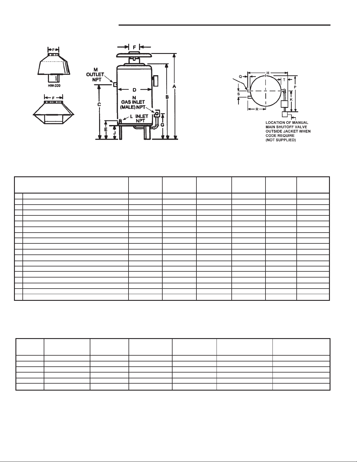
ROUGH-IN DIMENSIONS
HW/HWB-610
AND HW-670
NA TURAL GAS ONL Y
EXTRA OPENING
FOR THERMOMETER
AND RELIEF VALVE
HW/HWB-520, 610
AND HW--670
TABLE 1 MODELS
Prop. Nat.
DIMENSIONS IN INCHES
HWB/ HWB/ HWB/ HWB/ HWB/ HWB/
HW-300 HW-399 HW-420 HW-520 HW-610/670 HW-610/670
A Overall height 65 (1651) 57-1/8 (1451) 57-1/8 (1451) 68-5/16 (1735) 67 (1702) 64-3/4 (1645)
B Height to top of jacket 43-1/4 (1099) 45-1/8 (1146) 45-1/8 (1146) 56-1/4 (1429) 56-1/4 (1429) 56-1/4 (1429)
C Floor to center line water inlet 36 (914) 38-3/4 (984) 38-3/4 (984) 46 (1168) 46 (1168) 46 (1168)
D Diameter of jacket 25-1/4 (641) 27 (686) 27 (686) 27 (686) 27 (686) 27 (686)
E Floor to center line water outlet 12 (305) 12 (305) 12 (305) 12 (305) 12 (305) 12 (305)
F Draft diverter outlet diameter 8 (203) 10 (254) 10 (254) 10 (254) 12 (305) 12 (305)
G Floor to center line gas inlet 16-1/2 (419) 16-3/4 (425) 16-3/4 (425) 18 (457) 18 (457) 18 (457)
H Overall depth 29-5/8 (753) 31-1/2 (800) 31-1/2 (800) 36-1/2 (927) 36-1/2 (927) 36-1/2 (927)
J Support height 9 (229) 9 (229) 9 (229) 9(229) 9 (229) 9 (229)
K Width of control string (approx.) 14 (356) 14 (356) 14 (356) 11(279) 11 (279) 11 (279)
L Pipe size of water inlet (NPT) 1-1/4 1-1/2 1-1/2 2 2 2
M Pipe size of water outlet(NPT) 1-1/4 1-1/2 1-1/2 2 2 2
N Pipe size of gas inlet (NPT) 3/4 1 1 1 1 1
P Control string plus 1/2 jacket dia. (approx.) 26-5/8 (676) 27-1/2(699) 27-1/2 (699) 24-1/2 (622) 24-1/2 (622) 24-1/2 (622)
Q Water outlet to jacket 1 (25) 1 (25) 1 (25) 3-1/2 (89) 3-1/2 (89) 3-1/2 (89)
R Water inlet casting to center line of jacket 10-1/8 (257) 11-1/4 (286) 11-1/4 (286) 12 (305) 12 (305) 12 (305)
S Horizontal length between water inlet and outlet 5-3/8 (137) 5-1/2 (140) 5-1/2 (140) 5-3/4 (146) 5-3/4 (146) 5-3/4 (146)
T Control string from jacket 5 (127) 5 (127) 5 (127) 7 (178) 7 (178) 7 (178)
Approx. shipping weight lbs. (Kilograms) 240 (109) 291 (132) 291 (132) 361 (164) 361 (164) 361 (164)
NOTE: All dimensions in inches (millimeters) except pipe size which is NPT.
TABLE 2, SPECIFICATIONS - CANADIAN MODELS ONLY
Maximum
Maximum I.A.S. Maximum Max. Heat Transfer Max. Heat Transfer
Model Type of Gas BTUH(KW) BTUH(KW) Heat Loss Load Surface Area (Sq. Ft.) Surface Area (Sq. Ft.)
HWB-300 Natural & Propane 300,000 (88) 247,200 (72) 210,120 (62) 1,410 (.41) 1,051 (.31)
HWB-399 Natural & Propane 399,000 (116) 322,790 (95) 274,371 (80) 1,829 (.54) 1,372 (.40)
HWB-420 Natural & Propane 420,000 (123) 344,400 (101) 292,740 (86) 1.952 (57) 1,464 (.43)
HWB-520 Natural & Propane 520,000 (152) 429,000 (126) 364,650 (107) 2,431 (.71) 1,823 (.53)
HWB-610 Natural 610,000 (179) 502,600 (147) 427,210 (125) 2,848 (.83) 2,136 (.61)
HWB-610 Propane 610,000 (179) 488,000 (143) 414,800 (121) 2,765 (.81) 2,074 (.61)
Ratings shown are for current modern heating system design. Where A.O. Smith boilers are connected to heavy, cast iron radiator systems or where unusual pick-up or
large size piping conditions exist, reduce ratings by 10%.
NOTE: To compensate for the effects of high altitude areas above 2000 feet, the input, output and heating load ratings should be reduced
approximately 4% for each 1000 feet above sea level.
22
2
22
Page 3
TABLE 3, RECOVERY CAPACITIES - CANADIAN MODELS ONLY
Model (Btu/Hr.) Rise (F) 20 30 40 50 60 70 80 90 100 110 120 130 140
HW-300 300,000 LPH 5,505 3,670 2,753 2,202 1,835 1,573 1,376 1,223 1,001 1,001 918 847 786
HW-399 399,000 LPH 7,322 4,882 3,661 2,929 2,441 2,092 1,831 1,627 1,464 1,331 1,220 1,127 1,046
HW-420 420,000 LPH 7,708 5,138 3,854 3,083 2,569 2,202 1,927 1,713 1,542 1,401 1,285 1,186 1,101
HW-520 520,000 LPH 9,543 6,362 4,771 3,817 3,181 2,727 2,386 2,121 1,909 1,735 1,590 1,468 1,363
HW-610 610,000 LPH 11,194 7,463 5,597 4,478 3,731 3,198 2,799 2,488 2,239 2,035 1,866 1,722 1,599
Input Temp. (C) 11 17 22 26 33 39 44 50 56 61 67 72 78
GPH 1,455 970 727 582 485 416 364 323 291 264 242 224 208
GPH 1,935 1,290 967 774 645 553 484 430 387 352 322 298 276
GPH 2,036 1,358 1,018 815 679 582 509 453 407 370 339 313 291
GPH 2,521 1,681 1,261 1,008 840 720 630 560 504 458 420 388 360
GPH 2,958 1,972 1,479 1,183 986 845 739 657 592 538 493 455 423
33
3
33
Page 4

FOREWORD
CAUTION
TEXT PRINTED OR OUTLINED IN RED CONT AINS INFORMATION RELA TIVE
TO YOUR SAFETY. PLEASE READ THOROUGHLY BEFORE USING
APPLIANCE.
Detailed installation diagrams are in this manual. These diagrams will serve
to provide the installer with a reference for the materials and method of
piping suggested. IT IS NECESSARY THA T ALL W ATER AND GAS PIPING
AND THE ELECTRICAL WIRING BE INST ALLED AND CONNECTED AS
SHOWN IN THE DIAGRAMS.
CHECK THE DIAGRAMS THOROUGHL Y BEFORE STARTING INSTALLA TION
TO A VOID POSSIBLE ERRORS AND TO MINIMIZE TIME AND MATERIALS
COST .
This design complies with the latest edition of ANSI Z21.13.
CSA 4.9 low-pressure boiler .
Particular attention should be given to the installation of thermometers at
TABLE OF CONTENTS
PAGE
ROUGH-IN DIMENSIONS ................................................................... 2-3
FOREWORD ...................................................................................... 4
INSTALLA TION INSTRUCTIONS ........................................................ 4
Required Ability .......................................................................... 4
Installation As Boiler Replacement ............................................. 4
Location ...................................................................................... 5
Air Requirements........................................................................ 5-6
Chemical Vapor Corrosion ......................................................... 6
Installation Clearances ............................................................... 6
Levelling...................................................................................... 6
System Connections .................................................................. 6-9
Gas Connections ........................................................................ 9-11
Gas Pressure Regulators .......................................................... 11-12
Venting The Boiler - Standard Venting....................................... 12-14
Venting Maintenance - Standard Venting .................................. 15
Venting Sidewall (Optional) Power Vent System ...................... 15
Venting System .......................................................................... 15
Safety Relief Valves .................................................................. 15-16
Wiring Connections .................................................................... 16-31
Water Line Connections ............................................................. 32
Hard Water ................................................................................. 32
T ank Temperature Control .......................................................... 32-33
Low Water Cutoff ...................................................................... 33
Thermometers ............................................................................ 33
Drain Valve (Not Supplied)......................................................... 33
Closed Water System ................................................................ 33
Piping Diagrams .......................................................................... 34-45
the locations indicated in the diagrams as these are necessary for checking
the operation of the boiler.
MAKE SURE THE GAS ON WHICH THE BOILER WILL OPERA TE IS THE
SAME AS THA T SPECIFIED ON THE UNIT RATING PLA TE.
The boiler installation must conform to these instructions and the
requirements of the local authority having jurisdiction.
Where required by authority having jurisdiction, the installation must conform
to the Standard for Controls and Safety Devices for Automatically Fired
Boilers, ANSI/ASME CSD-1.
In absence of local code requirements, the boiler installation must conform
National Fuel Gas Code, ANSI Z223.1 and/or CAN/CSA B-149.1-00
to the
Installation Codes.
These manuals can be purchased from the CSA International, 8501 East
Pleasant Valley Road, Cleveland, OH 44131 or 178 Rexdale Boulevard,
T oronto, Ontario Canada M9W1R3.
PAGE
STA RT-UP AND OPERATING INSTRUCTIONS .................................. 45
Filling And Venting ...................................................................... 46
Pilot and Main Burner ................................................................. 46
Lighting Instructions ................................................................... 47-48
Pilot and Main Burner (Continued) ............................................. 49-51
Electronic Intermittent Pilot Ignition Control ................................. 51
Normal Operating Sequence With Honeywell S-8600H or
S-8610M Intermittent Ignition Control (I.I.D.) ............................... 52
High Altitude Installations ........................................................... 52
Thermal Balancer ....................................................................... 52
Coil High Limit Control (Protector Switch).................................. 52-53
Pressure Reducing Valve .......................................................... 53
Safety Flow Switch ................................................................... 53-54
Safety Relief Valve Maintenance ............................................... 54
Replacement Parts ..................................................................... 54
REMOVAL OF EXISTING BOILER FROM A COMMON
VENTING SYSTEM............................................................................ 54
GENERAL MAINTENANCE ................................................................ 55
Relief Valve ................................................................................ 55
CLEANING AND FLUSHING INSTRUCTIONS .................................... 55
Internal Contaminants ................................................................. 55
Hot Water Supply Boilers - Preventive Maintenance ................ 55
Deliming ....................................................................................... 55-56
Deliming Solvents ....................................................................... 56
Heavy Lime Deposits ................................................................. 56
Removing Silicate ....................................................................... 56
PRE-TROUBLE-SHOOTING ............................................................... 57
TROUBLE-SHOOTING....................................................................... 57-61
LIMITED WARRANTY........................................................................ 62
INST ALLA TION INSTRUCTIONS
REQUIRED ABILITY
INST ALLATION OR SERVICE OF THIS BOILER REQUIRES ABILITY
EQUIVALENT TO THAT OF A LICENSED TRADESMAN IN THE
FIELD INVOLVED. PLUMBING, AIR SUPPLY, VENTING, GAS
SUPPL Y AND ELECTRICAL WORK ARE REQUIRED.
INST ALLA TION AS BOILER REPLACEMENT
Installation as boiler replacement on an old system with large
water volume may experience condensation within the boiler on
cold starts. This condensing of water vapor in the combustion
area can be prevented if a portion of the system water flow is
diverted past the boiler to cause an increase in boiler temperature
rise.
With old systems where water temperature can be expected to
drop appreciably due to long standby periods, a bypass pipe of at
least 1" size with a balancing cock should be installed between
the boiler inlet and outlet. When the system first starts, the valve
should be slowly opened until the condensing ceases. This
adjustment remains at a permanent setting to establish required
temperature rise across the boiler.
The equipment shall be installed in accordance with those
installation regulations in force in the local area where the
installation is to be made. These shall be carefully followed in all
cases. Authorities having jurisdiction shall be consulted before
installations are made.
44
4
44
Page 5

LOCATION
When installing the boiler, consideration must be given to proper
location. Location selected should be as close to the stack or
chimney as practicable with adequate air supply and as centralized
with the piping system as possible. This location should also be
such that the gas ignition system components are protected from
water (dripping, spraying, etc.) during appliance operation and
service (circulator replacement, control replacement, etc.).
THE BOILER MUST NOT BE INST ALLED ON CARPETING.
THE BOILER SHOULD NOT BE LOCATED IN AN AREA WHERE IT
WILL BE SUBJECT TO FREEZING.
LOCATE IT NEAR A FLOOR DRAIN. THE BOILER SHOULD BE
LOCA TED IN AN AREA WHERE LEAKAGE FROM THE BOILER OR
CONNECTIONS WILL NOT RESULT IN DAMAGE TO THE
ADJACENT AREA OR TO LOWER FLOORS OF THE STRUCTURE.
WHEN SUCH LOCATIONS CANNOT BE AVOIDED, A SUITABLE
DRAIN P AN SHOULD BE INSTALLED UNDER THE BOILER. Such
pans should be fabricated with sides at least 60mm (2-1/2") deep,
with length and width at least 50mm (2") greater than the diameter
of the boiler and must be piped to an adequate drain. The pan
must not restrict combustion air flow.
WARNING
FOR SAFE OPERATION PROVIDE ADEQUATE AIR FOR
COMBUSTION AND VENTILATION. AN INSUFFICIENT SUPPLY
OF AIR WILL CAUSE RECIRCULATION OF COMBUSTION
PRODUCTS RESUL TING IN AIR CONTAMINATION THA T MA Y BE
HAZARDOUS TO LIFE. SUCH A CONDITION OFTEN WILL
RESUL T IN A YELLOW , LUMINOUS BURNER FLAME, CAUSING
CARBONING OR SOOTING OF THE COMBUSTION CHAMBER,
BURNERS AND FLUE TUBES AND CREATES A RISK OF
ASPHYXIATION.
UNCONFINED SPACE
In buildings of conventional frame, brick or stone construction,
unconfined spaces may provide adequate air for combustion, and
draft hood dilution.
If the unconfined space is within a building of tight construction
(buildings using the following construction: weather stripping, heavy
insulation, caulking, vapor barrier, etc.) air for combustion,
ventilation, and draft hood dilution must be obtained from outdoors
or spaces freely communicating with the outdoors. The installation
instructions for confined spaces in tightly constructed buildings
must be followed to ensure adequate air supply.
CONFINED SPACE
WARNING
KEEPING BOILER AREA CLEAR AND FREE FROM COMBUSTIBLE
MA TERIALS, GASOLINE AND OTHER FLAMMABLE V APORS AND
LIQUIDS.
WARNING
THERE IS A RISK IN USING FUEL BURNING APPLIANCES SUCH
AS BOILERS IN ROOMS OR AREAS WHERE GASOLINE, OTHER
FLAMMABLE LIQUIDS OR ENGINE DRIVEN EQUIPMENT OR
VEHICLES ARE STORED, OPERATED OR REPAIRED.
FLAMMABLE VAPORS ARE HEAVY AND TRAVEL ALONG THE
FLOOR AND MA Y BE IGNITED BY THE IGNITER OR MAIN BURNER
FLAMES CAUSING FIRE OR EXPLOSION. SOME LOCAL CODES
PERMIT OPERATION OF GAS APPLIANCES IF INSTALLED
18 INCHES OR MORE ABOVE THE FLOOR. THIS MA Y REDUCE
THE RISK IF LOCATION IN SUCH AN AREA CANNOT BE A VOIDED.
WARNING
FLAMMABLE ITEMS, PRESSURIZED CONTAINERS OR ANY
OTHER POTENTIAL FIRE HAZARDOUS ARTICLES MUST NEVER
BE PLACED ON OR ADJACENT TO THE BOILER. OPEN
CONTAINERS OF FLAMMABLE MA TERIAL MUST NOT BE STORED
OR USED IN THE SAME ROOM WITH THE BOILER.
A hot water boiler installed above radiation level or as required by
the authority having jurisdiction, must be provided with a low water
cutoff device at the time of boiler installation.
AIR REQUIREMENTS
Provisions for combustion and ventilation air in accordance with
section 5.3, Air for Combustion and Ventilation, of the National
Fuel Gas Code, ANSI Z223.1, or sections 7.2, 7.3, or 7.4 of
CAN/CSA B149.1-00, Installation Codes, or applicable provisions
of the local building codes.
Provisions for vent, bleed and gas relief lines (when applicable).
(a) U. S. INSTALLATIONS
When drawing combustion and dilution air from inside a
conventionally constructed building to a confined space, such a
space shall be provided with two permanent openings, ONE
WITHIN 12 INCHES OF THE ENCLOSURE TOP AND ONE
WITHIN 12 INCHES OF THE ENCLOSURE BOTTOM. Each
opening shall have a free area of at least one square inch per
1000 Btuh of the total input of all appliances in the enclosure, but
not less than 100 square inches.
If the confined space is within a building of tight construction, air
for combustion, ventilation, and draft hood dilution must be
obtained from outdoors. When directly communicating with the
outdoors or communicating with the outdoors through vertical
ducts, two permanent openings, located in the above manner,
shall be provided. Each opening shall have a free area of not less
than one square inch per 4000 Btuh of the total input of all
appliances in the enclosure. If horizontal ducts are used, each
opening shall have a free area of not less than one square inch
per 2000 Btuh of the total input of all appliances in the enclosure.
(b) CANADIAN INSTALLA TIONS
Ventilation of the space occupied by the boiler(s) shall be provided
by an opening for ventilation air at the highest practical point
communicating with outdoors. The total cross-sectional area shall
be at least 10% of the area of the combustion air opening but in no
case shall the cross-sectional area be less than 10 square inches
(6500 mm
2
)
In additional to the above, there shall be permanent air supply
opening(s) having a cross-sectional area of not less than 1 square
inch per 7,000 BTUH (310 mm
1,000,000 BTUH
plus 1 square inch per 14,000 BTU in excess of
2
/KW) up to and including
1,000,000 BTUH. This opening(s) shall be located at, or ducted
to, a point neither more than 18" (450 mm) nor less than 6 inches
(150 mm) above the floor level.
Where power vented equipment is used in the same room as the
boiler, sufficient air openings must be supplied.
Keep appliance area free of combustible or flammable liquids.
Do not obstruct the flow of combustion or ventilating air.
UNDERSIZED OPENINGS MAY RESULT IN INSUFFICIENT AIR
FOR COMBUSTION.
55
5
55
Page 6
Where an exhaust fan is installed in the same room with a boiler,
sufficient openings for air must be provided in the walls.
UNDERSIZED OPENINGS WILL CAUSE AIR TO BE DRAWN INTO
THE ROOM THROUGH THE CHIMNEY, CAUSING POOR
COMBUSTION. SOOTING MAY RESULT WITH AN INCREASED
RISK OF ASPHYXIA TION.
CHEMICAL V APOR CORROSION
WARNING
CORROSION OF THE FLUEWAYS AND VENT SYSTEM MAY
OCCUR IF AIR FOR COMBUSTION CONTAINS CERTAIN
CHEMICAL V APORS WHICH BREAK DOWN INTO ACIDS A T HIGH
TEMPERATURE. SUCH CORROSION MA Y RESUL T IN F AILURE
AND RISK OF ASPHYXIA TION.
Water boiler corrosion and component failure can be caused by
the heating and breakdown of airborne chemical vapors. Spray
can propellants, cleaning solvents, refrigerator and air conditioning
refrigerants, swimming pool chemicals, calcium and sodium
chloride, waxes, and process chemicals are typical compounds
which are corrosive. These materials are corrosive at very low
concentration levels with little or no odor to reveal their presence.
Products of this sort must not be stored near the boiler. Also, air
which is brought in contact with the water boiler should not contain
any of these chemicals. If necessary, uncontaminated air should
be obtained from remote or outside sources.
INST ALLA TION CLEARANCES
These boilers are approved for installation on combustible flooring
in an alcove with minimum clearance to combustibles of:
TABLE 4
HWB/HW HWB/HW HWB/HW HWB/HW HWB/HW
300 399 420 52 0 610 & 670
TOP 28" (71 1.2) 32" (812.8) 24" (609.6) 24" (609.6) 24" (609.6)
SIDES 6" (152.4) 6" (152.4) 24" (609.6) 24" (609.6) 24" (609.6)
REAR 6" (152.4) 6" (152.4) 24" (609.6) 24" (609.6) 24" (609.6)
VENT 6" (152.4) 6" (152.4) 6" (152.4) 6" (152.4) 6" (152.4)
Two inch (50.8mm) clearance is allowable from combustible
construction for hot water pipes.
Sufficient area should be provided at the front and rear of the unit
for proper servicing. Clearances of 24 inches (609.4mm) in the
rear and 48 inches (1,219mm) in the front are required by code. In
a utility room installation, the door shall be wide enough to allow
the boiler to enter or to permit the replacement of another appliance
such as a water heater.
LEVELLING
Each unit should be checked after installation to be certain that it is
level.
If the unit is not level, insert metal shims under the legs of the unit
to correct this condition.
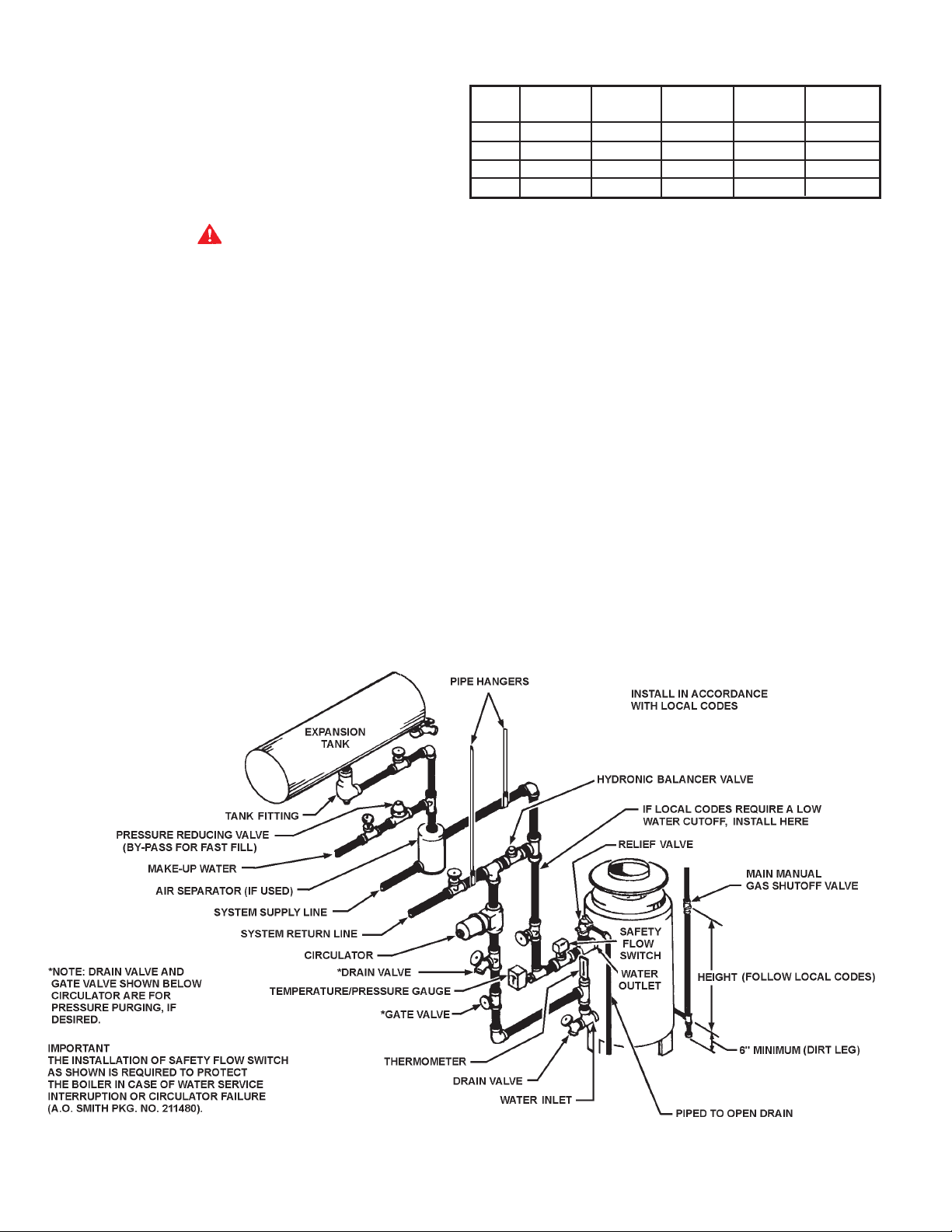
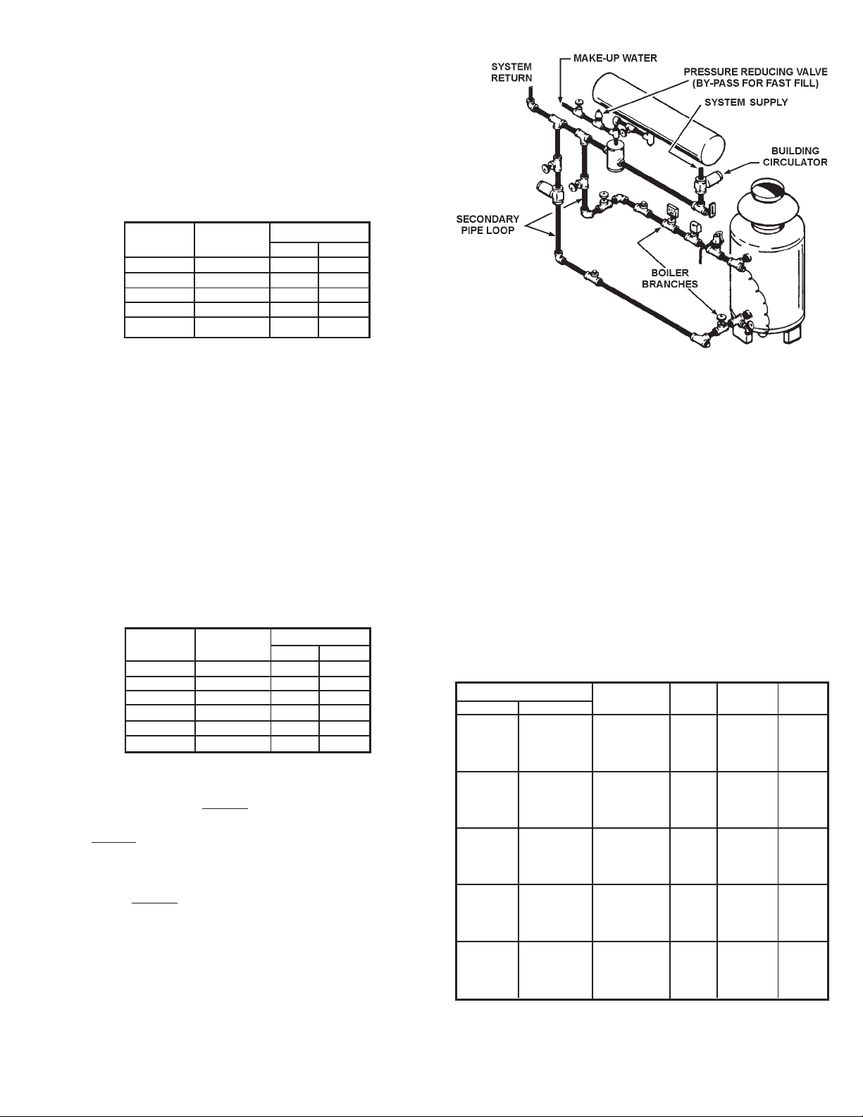
SYSTEM CONNECTIONS
The system installation must conform to these instructions and to
the requirements of the local code authority having jurisdiction.
Good practice requires that all heavy piping be supported.
A TYPICAL BOILER INST ALLATION
FIGURE 1
66
6
66
Page 7
1. CONVENTIONAL INST ALLA TIONS
All modern hydronic type boilers are exceptionally fast heating units.
The low water volumes in relation to firing rates require special
attention to water flow rates for smooth, efficient operation. These
considerations for the A. O. Smith copper heat exchanger boilers
are covered below.
0
Conventional 10
C (200F) drop in systems for a fully loaded boiler
will maintain the following approximate flow rates:
U.S. CANADIAN
MODELS MODELS LPM GPM
HW-300 HWB-300 87 23
HW-399 HWB-399 114 30
HW-420 HWB-420 132 35
HW-520 HWB-520 148 39
HW-670 HWB-610 175 46
Figure 1 shows a typical installation of the boiler with pipe sizing
and circulator selected by the installer to provide adequate water
flow whenever the boiler is firing.
In a system with several large zones of which any might be smaller
than approximately 1/3 of the system should include a hydronic
balancer as shown in fig. 1. The balancer connects between the
system supply and the return line before the circulator inlet.
Adjustment of the balancing cock should permit adequate boiler
flow rate when only the smallest zone is in operation.
Attention should be given to balancing inputs and water flow rates
where wide variations of system flow rates can occur.
The recommended minimum flow rates that will result in
approximately 30
0
C (500F) temperature rise across the boiler are
as follows:
ONE BOILER INSTALLED
INDEPENDENT OF THE PRIMARY SYSTEM
FIGURE 2
Total heating requirements for the building can be supplied by a
series of boiler loops all connecting to a common pipe joining the
system supply and return mains. The supply and return branches
of each boiler loop must join the common pipe only a short nipple
length apart. The different sets of branches should be installed
reasonably close together, but not necessarily to the short nipple
length as required for the supply and return of each set. These
branches may be made with tees or with welded connections.
The installer is reminded that the total boiler flow rates need not
match the system flow rate.
U.S. CANADIAN
MODELS MODELS LPM GPM
HW-300 HWB-300 34 9
HW-399 HWB-399 45 12
HW-420 HWB-420 53 14
HW-520 HWB-520 61 16
HW-610 HWB-610 69 18
HW-670
76 20
If system flow rate is unknown, or if zoning creates extreme
variations in flow rates, the boiler should be installed as shown
in fig. 2 for A. O. Smith
LINEAR-TEMP INSTALLA TIONS
2.
LINEAR-TEMP installations.
A. New Installations
A. O. Smith
LINEAR-TEMP systems have been designed to provide
efficient, trouble-free operation of the boiler sizes covered in this
manual with any of the following conditions:
a. Unknown system flow rate
b. Varying flow rate as with zoned systems
c. Multiple boiler installations
Figure 2 shows piping and accessory arrangement for a boiler
pumped independent of the primary system mains. Pipe sizing
and boiler loop pump selection data are shown in Table 5 for
several different temperature rises across the boilers.
TABLE 5
PUMP AND PIPE SIZING DA T A
(PIPING FROM TEES IN MAIN TO BOILER BRANCHES)
Quantity and Model Temp. *Pump Pipe
U. S Canadian Rise°C (°F) G.P.M. Size Size
10 (20) 23 1-1/2"PR 2"
HW-300 1 HWB-300 15 (30) 15 1 50 1-1/2"
15 (30) 15 125 1-1/4"
20 (40) 11 10 0 1"
10 (20) 30 60-13 2"
HW-399 1 HWB-399 15 (30) 20 1-1/2"HV 1-1/2"
20 (40) 15 150 1-1/2"
20 (40) 15 125 1-1/4"
10 (20) 32 60-13 2"
HW-420 1 HWB-420 15 (30) 21 1-1/2"HV 1-1/2"
20 (40) 16 150 1-1/2"
20 (40) 16 125 1-1/4"
10 (20) 39 2-1/2" 2-1/2"
HW-520 1 HWB-520 10 (20) 26 1-1/2"HV 2"
17 (35) 23 1-1/2"HV 1-1/2"
20 (40) 20 150 1-1/2"
10 (20) 51 60-13 3"
HW-670 1 HWB-610 15 (30) 34 2-1/2" 2-1/2"
17 (35) 29 2" 2"
20 (40) 25 1-1/2"HV 1-1/2"
NOTE: Pipe loop sizes and pump selections based on
50 equivalent feet of pipe and fittings.
*All pump sizes listed are B & G model numbers.
77
7
77
Page 8
NO . SUGGESTED ITEMS FOR INST ALLA TION
1 Short pipe nipple and pair of boiler loop tees in piping
between system supply and return. One set per each
group of boilers
2 Boiler pipe loop. See piping sizing data above.
3 Boiler circulator. See pump sizing data above.
4 Thermometer.
5 Theraltimeter.
6 Plug cock to control flow rate.
7 Safety flow switches. For interlock with other systems or
instead of low water cutoff.
8 Relief valve.
9 With one -300, -399 or -420 item 9 is - sensing
element of remote control.
With a group of -300's, -399's or -420's, item 9 is - for
1st. boiler, the sensing element as above. For additional
boilers, install a 2nd. limit control if required by local codes.
With any -520, -610 or 670 boilers, install 2nd. limit control
here if required by local code.
BOILER INLET - OUTLET SIZES
10 HWB-300 - 1-1/4", HWB-399 - 1-1/2", HWB-420-1-1/2",
HWB-520 & HWB-610 - 2". Canadian Models
10 HW-300 - 1-1/4", HW-399 - 1-1/2", HW-420-1-1/2",
HW-520 & HW-670 - 2". U.S. Models
MINIMUM BRANCH SIZES TO BOILERS
1 1 HWB-300 - 1-1/4" HWB-520, 610 (Single boiler
HWB-399 - 1-1/2" per pump) 2"
HWB-420 - 1-1/2" Canadian Models
1 1 HW-300 - 1-1/4" HW-520, 670 (Single boiler
HW-399 - 1-1/2" per pump) 2"
HW-420 - 1-1/2" U.S. Models
12 Flow control valve. Required only if flow rate of system
primary is excessive for size of boiler branch tees or if
chilled water main is above boilers.
13 System supply temperature thermometer.
14 Boiler headers for three (3) boilers can be larger than pipe loop,
if desired, to aid in balancing.
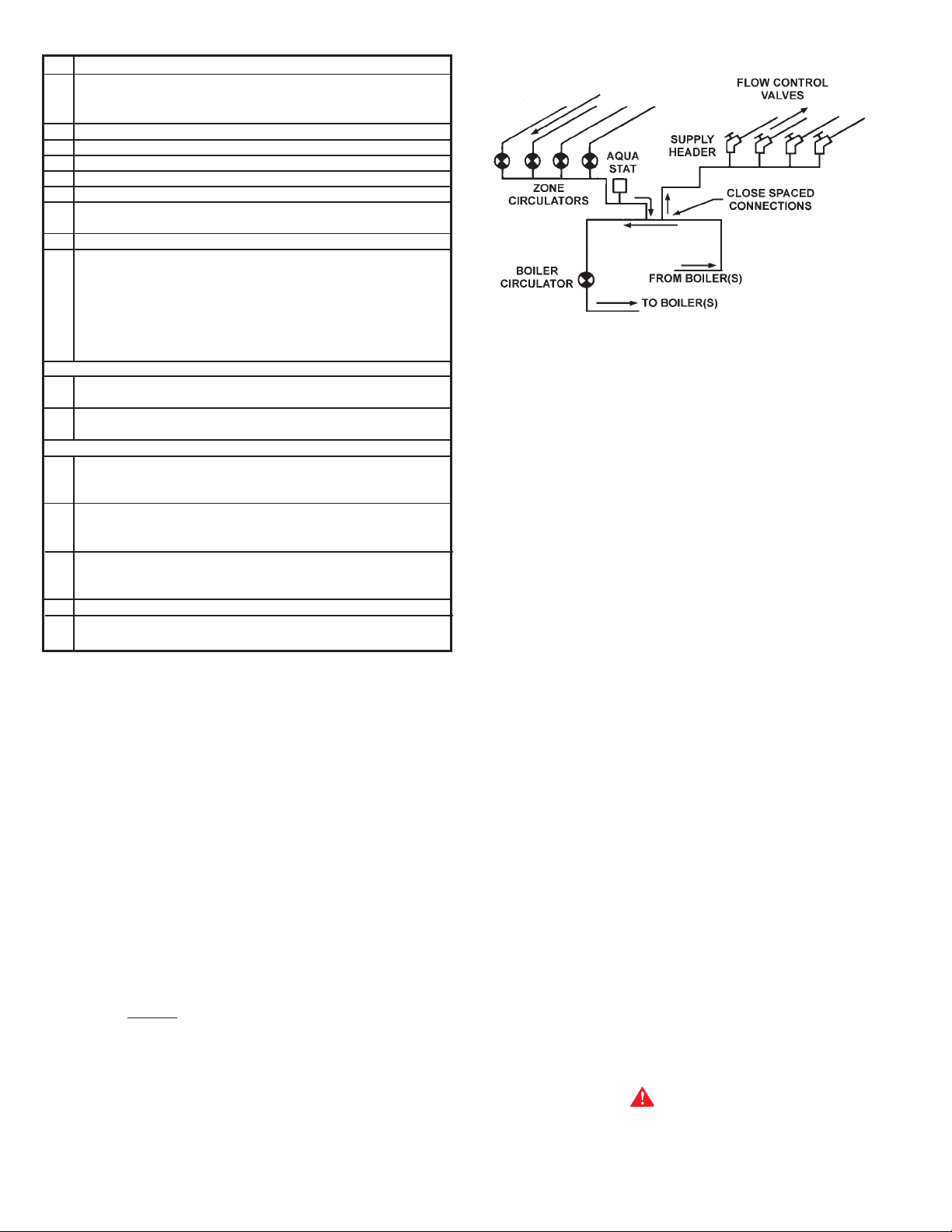
SCHEMATIC OF THE LINEAR-TEMP® SYSTEM
FIGURE 3
Supply and return headers of the old system should be connected
to the boiler loop with a pair of tees set close together. The boiler
loop pump and the boiler(s) should be wired to operate only when
any of the system pumps are in operation. The number of zone
pumps that may be in operation at any particular time will take their
required flow rate out from the first tee in the boiler piping. This
water will be circulated through the proper branches from the supply
header to the zones calling for heat. The water will be brought
back to the return header and then into the second tee in the boiler
pipe loop. There will be no conflict between the boiler pump and
the zone pumps when the two tees in the boiler loop are placed
close together.
Normal use of flow control valves is required to prevent cross
circulation of zones as with any multiple pump system. Flow control
is not required on boiler circuit.
The system flow rate is selected to give the desired system
temperature drop - depending on the design criteria.
The boiler generator flow rates, on the other hand, should be
selected to give the temperature rise through the generator that is
both economical and offers the best generator efficiency.
The boiler temperature rise is normally between 10
0
(20
F and 400F). The system temperature that will be introduced
0
C and 200C
to the boiler (inlet temperature) plus the selected boiler temperature
rise selected from PUMP AND PIPE SIZING DAT A should not exceed
the high limit control setting of 115
0
C (2400F).
There should be a relation of the minimum system load to the size
boiler selected as the first firing or base boiler. This will stabilize
operation during minimum load periods.
B. Commercial Boiler Replacements
Application of
LINEAR-TEMP® to a commercial boiler replacement
with an old multiple pump installation is an excellent way to
modernize the system. The A. O. Smith boiler(s) should be
installed on a pipe loop with a separate circulating pump selected
from PUMP AND PIPE SIZING DA T A T ABLE.
Figure 3 shows a line drawing of how the system headers should
be connected to the pipe loop installed with the replacement
boiler(s). Make-up water connections and accessories are not
shown.
Attention should be given to balancing gas inputs and water flow
rates. Large systems with multiple boilers should include main
water temperature control (with or without outdoor reset) to stage
the boilers on and off in relation to the load on the system.
3. WA TER SUPPL Y LINE
These boilers can be used ONLY in a forced circulation hot water
heating system. Since most forced circulation systems will be of
the closed type, install the water supply line as shown on piping
diagrams, fig. 1 or 2.
Fast filling of large pipe, old radiator installations and pressure
purging of series loop systems (where high pressures are not
available) requires bypassing of the pressure reducing valve.
Generally, pressure purging is not possible with a well pump
system. High point air venting is essential.
If the system is of the open type, a pressure reducing valve will not
be required as the water supply to the system will be controlled by
a manually operated valve. An overhead surge tank is required.
4. EXPANSION T ANK
CAUTION
A closed system will exist if a check valve (without bypass), pressure
reducing valve (without bypass), or a water meter (without bypass)
is installed in the cold water line between the water heater and
street main (or well).
88
8
88
Page 9
Excessive pressure may develop causing premature tank failure
or intermittent relief valve operation.
This is not a warranty failure.
An expansion tank or a similar device may be required in the inlet
supply line between the appliance and the meter or valve to
compensate for the thermal expansion of water under supply
pressure, see figure 1.
If the boiler is connected to chilled water piping or its heating coils
are exposed to refrigerated air, the boiler piping system must be
equipped with flow valves or other automatic means to prevent
gravity circulation through the boiler during the cooling cycle.
8. CIRCULATING PUMP
An air separator as shown in the piping diagrams is recommended
especially for modern commercial hydronic systems.
5. VENT V ALVES
It is recommended that automatic, loose key or screwdriver type
vent valves be installed at each convector or radiator.
6. MANIFOLD HEADERS
Split systems with individual supply and return lines from the boiler
room should normally have this piping connected to supply and
return manifold headers near the boiler. To achieve good water
distribution with maximum pressure drop for several circuits,
manifolds of at least 2-1/2" (64mm) diameter are suggested on
HWB/HW-399, HWB/HW-420, HWB/HW-520, HWB/HW-610 and
HW-670 units. HWB/HW-300 units should have 1-1/2" (38mm)
diameter manifolds.
The circuits should be spaced on the header at a minimum of
3" (76mm) center to center. Install a balancing cock in each return
line.
Manifold headers are recommended for split systems with or
without zone valves and also those installations with zone
circulators. If the system is to be split at remote points, good
practice requires special attention be given to main pipe sizing to
allow balancing of water flow.
The boiler piping system of a hot water boiler connected to heating
coils located in air handling units where they may be exposed to
refrigerated air circulation must be equipped with flow control valves
or other automatic means to prevent gravity circulation of the boiler
water during the cooling cycle.
CONSTANT CIRCULATING PUMP OPERATION OF THE BOILER
VOIDS THE W ARRANTY. Constant water flow through the unit will
“wash” away the copper’s natural protective coating. This is called
velocity erosion. This erosion is not as great a problem when
intermittent circulating operation is used per the recommended
installation procedure. Constant circulation of water through the
building’s system main is permissible as long as the water does
not constantly flow through the boiler. Only all bronze or stainless
steel circulators are to be used with the unit when it is installed in
HOT WA TER SUPPL Y SYSTEMS .
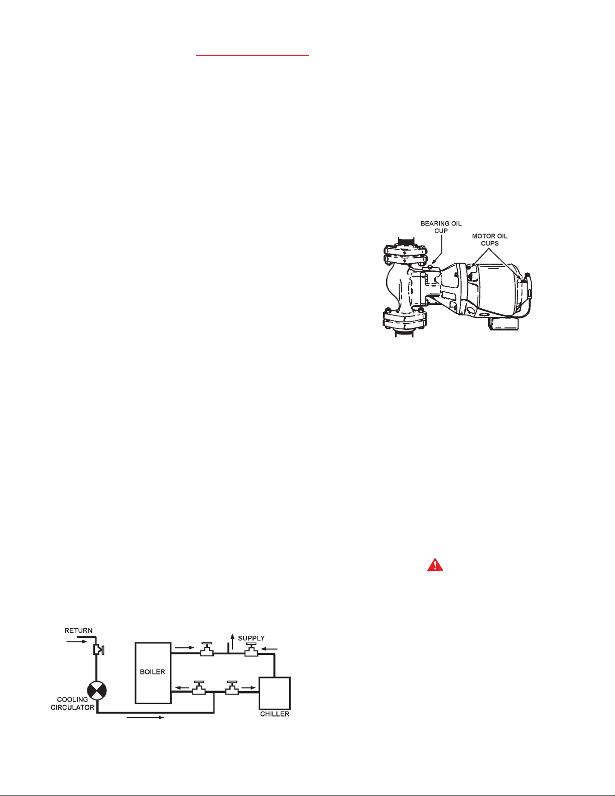
A TYPICAL CIRCULA TING PUMP
FIGURE 5
Although each circulator that requires oiling is oiled and operated
by the manufacturer, IT MUST BE OILED AGAIN BEFORE
OPERATED. Oil the three oil cup s (2 on the motor, 1 on the pump)
as instructed on the oil tube supplied with the unit, fig 5.
Thereafter, during the heating season, lubricate the three oil cups
at least once every four months. Combination heating-cooling
systems should be lubricated every four months year ‘round.
Use 2 or 3 teaspoonsful in bearing oil cups, fig. 5, and 10 or
12 drops in the motor oil cups. Use No. 20 non-detergent motor
oil.
7. COOLING PIPING
When the boiler is used in conjunction with a refrigeration system
it must be installed so that the chilled medium is piped in parallel
with the boiler with appropriate valves to prevent the chilled medium
from entering the boiler, fig. 4.
Water temperature in the heating system must be reduced to less
0
than 100
F (38°C) before cooling system is started, or damage to
the chiller unit may occur.
SCHEMATIC SHOWING PROPER PIPING ISOLA TION
OF THE BOILER FROM THE CHILLER
FIGURE 4
Follow the same oiling procedure if a replacement circulator is
installed into the system.
GAS CONNECTIONS
WARNING
THIS BOILER IS NOT INTENDED TO OPERA TE AT GAS SUPPLY
PRESSURE OTHER THAN SHOWN ON THE RATING PLATE.
EXPOSURE TO HIGHER GAS SUPPL Y PRESSURE MA Y CAUSE
DAMAGE TO GAS VA LVES WHICH CAN RESULT IN FIRE OR
EXPLOSION. IF OVERPRESSURE HAS OCCURRED SUCH AS
THROUGH IMPROPER TESTING OF GAS LINES OR EMERGENCY
MALFUNCTION OF THE SUPPL Y SYSTEM, THE GAS VA LVES MUST
BE CHECKED FOR SAFE OPERATION. MAKE SURE THAT THE
OUTSIDE VENTS ON THE SUPPLY REGULATORS AND THE
SAFETY VENT V ALVES ARE PROTECTED AGAINST BLOCKAGE.
THESE ARE PARTS OF THE GAS SUPPLY SYSTEM, NOT THE
BOILER. VENT BLOCKAGE MA Y OCCUR DURING ICE BUILD-UP
OR SNOW STORMS.
WHEN LOCAL CODES REQUIRE A MAIN MANUAL SHUTOFF
V ALVE OUTSIDE THE BOILER JACKET , A SUIT ABLE MAIN MANUAL
SHUTOFF VALVE MUST BE INSTALLED IN A LOCATION
COMPL YING WITH THOSE CODES.
99
9
99
Page 10
IT IS IMPORT ANT TO GUARD AGAINST GAS V ALVE FOULING FROM
CONT AMINANTS IN THE GAS WA YS. SUCH FOULING MA Y CAUSE
IMPROPER OPERATION, FIRE OR EXPLOSION.
IF COPPER SUPPLY LINES ARE USED THEY MUST BE
CERTIFIED FOR GAS SERVICE.
BEFORE ATTACHING THE GAS LINE BE SURE THAT ALL GAS
PIPE IS CLEAN ON THE INSIDE.
TO TRAP ANY DIRT OR FOREIGN MATERIAL IN THE GAS SUPPL Y
LINE, A DIRT LEG (SOMETIMES CALLED DRIP LEG or sediment
trap) MUST BE INCORPORA TED IN THE PIPING, SEE FIG . 1. The
dirt leg must be readily accessible and not subject to freezing
conditions. INSTALL IN ACCORDANCE WITH
RECOMMENDA TIONS OF SERVING GAS SUPPLIERS. (Refer to
National Fuel Gas Code, ANSI Z223.1 and/or
CAN/CSA-B 149.1-00 Installation Codes.
To prevent damage, care must be taken not to apply too much
torque when attaching gas supply pipe to gas valve gas inlet.
Fittings and unions in the gas line must be metal to metal type.
Apply joint compounds (pipe dope) sparingly and only to the male
threads of pipe joints. Do not apply compound to the first two
threads. Use compounds resistant to the action of liquefied
petroleum gases.
THE BOILER AND ITS GAS CONNECTIONS MUST BE LEAK
TESTED BEFORE PLACING THE BOILER IN OPERATION. Use
soap and water solution or other material acceptable for the
purpose in locating gas leaks. DO NOT USE MA TCHES, CANDLES,
FLAME OR OTHER SOURCES OF IGNITION FOR THIS PURPOSE.
DISCONNECT THE BOILER AND ITS MAIN MANUAL GAS
SHUTOFF VALVE FROM THE GAS SUPPLY PIPING SYSTEM
DURING ANY PRESSURE TESTING OF THE GAS SUPPLY
SYSTEM OVER 1/2 PSIG (3.5kPa).. THE GAS SUPPL Y LINE MUST
BE CAPPED WHEN NOT CONNECTED TO THE BOILER.
2A.SIZING GAS SUPPLY LINE (For single boiler installations and
for installations of multiples of two or three of same size boilers).
Use table 6, or CAN/CSA B149.1-00 (latest recent edition) to size
iron pipe or equivalent gas supply line. Table 6 is based on a
pressure drop of 0.3 inches of water and a specific gravity of 0.60
approximately that of natural gas. (LP gas has an S.G. of about
1.53). If the service pressure is five inches water column or less,
use one pipe size larger than specified in table 6 in order to minimize
pressure drop in the line.
TABLE 6
MAXIMUM CAPACITY OF PIPE IN CUBIC FEET OF GAS PER
HOUR (BASED UPON A PRESSURE DROP OF 0.3 INCH WA TER
COLUMN AND 0.6 SPECIFIC GRA VITY GAS)
Length
Meters
From Gas (Nominal Iron Pipe Size (Inches)
Meter 1/2 3/4 1 1 1/4 1 1/2 2 2 1/2 3 4
3 (10) 132 278 520 1,050 1,600 3,050 4,800 8,500 17,500
6 (20) 92 190 350 730 1,100 2,100 3,300 5,900 12,000
9 (30) 73 152 285 590 890 1,650 2,700 4,700 9,700
12 (40) 63 130 245 500 760 1,450 2,300 4,100 8,300
15 (50) 56 115 215 440 670 1,270 2,000 3,600 7,400
18 ((60) 50 105 195 400 610 1,150 1,850 3,250 6,800
21 (70) 46 96 180 370 560 1,050 1,700 3,000 6,200
24 (80) 43 90 170 350 530 990 1,600 2,800 5,800
27 (90) 40 84 160 320 490 930 1,500 2,600 5,400
30 (100) 38 79 150 305 460 870 1,400 2,500 5,100
38 (125) 34 72 130 275 410 780 1,250 2,200 4,500
45 (150) 31 64 120 250 380 710 1,130 2,000 4,100
53 (175) 28 59 110 225 350 650 1,050 1,850 3,800
60 (200) 26 55 100 210 320 610 980 1,700 3,500
*The heating value of Natural Gas is approximately 1,050 Btu/Ft.3.
Propane (LP) Gas has a heating value of approximately 2,500 Btu/Ft3.
1 cu. meter=35.31 cu. feet.
Where it is necessary to use more than the average number of
pipe fittings i.e. elbows, tees, and valves in gas supply line, use a
pipe larger than specified to compensate for increased pressure
drop.
THE BOILER MUST BE ISOLATED FROM THE GAS SUPPLY
PIPING SYSTEM BY CLOSING ITS MAIN MANUAL GAS SHUTOFF
VA LVE DURING ANY PRESSURE TESTING OF THE GAS SUPPL Y
PIPING SYSTEM AT TEST PRESSURES EQUAL TO OR LESS
THAN 1/2 PSIG (3.5kPa).
PURGING
Gas line purging is required with new piping or systems in which
air has entered.
CAUTION
PURGING SHOULD BE PERFORMED BY PERSONS
EXPERIENCED IN THIS TYPE GAS SERVICE TO A VOID RISK OF
FIRE OR EXPLOSION. PURGE DISCHARGE MUST NOT ENTER
CONFINED AREAS OR SP ACES WHERE IGNITION CAN OCCUR.
THE AREA MUST BE WELL VENTILA TED AND ALL SOURCES OF
IGNITION MUST BE INACTIV ATED OR REMOVED.
1. CORRECT GAS
Make sure the gas on which the boiler will operate is the same as
that specified on the boiler rating plate. Do not install the boiler if
equipped for a different type gas — consult your supplier.
2B. SIZING GAS SUPPLY LINE (For multiples of over three boilers
of same size or for multiple installations of two or more mixed
sizes).
Capacities in cubic feet per hour of 0.60 specific gravity gas for
different sizes and lengths are shown in table 6. No additional
allowance is necessary for an ordinary number of fittings.
Applications of the gravity factor converts the figures given in table
6 to capacities with another gas of different specific gravity. Such
application is accomplished by multiplying the capacities given in
table 6 by the multipliers shown in table 7.
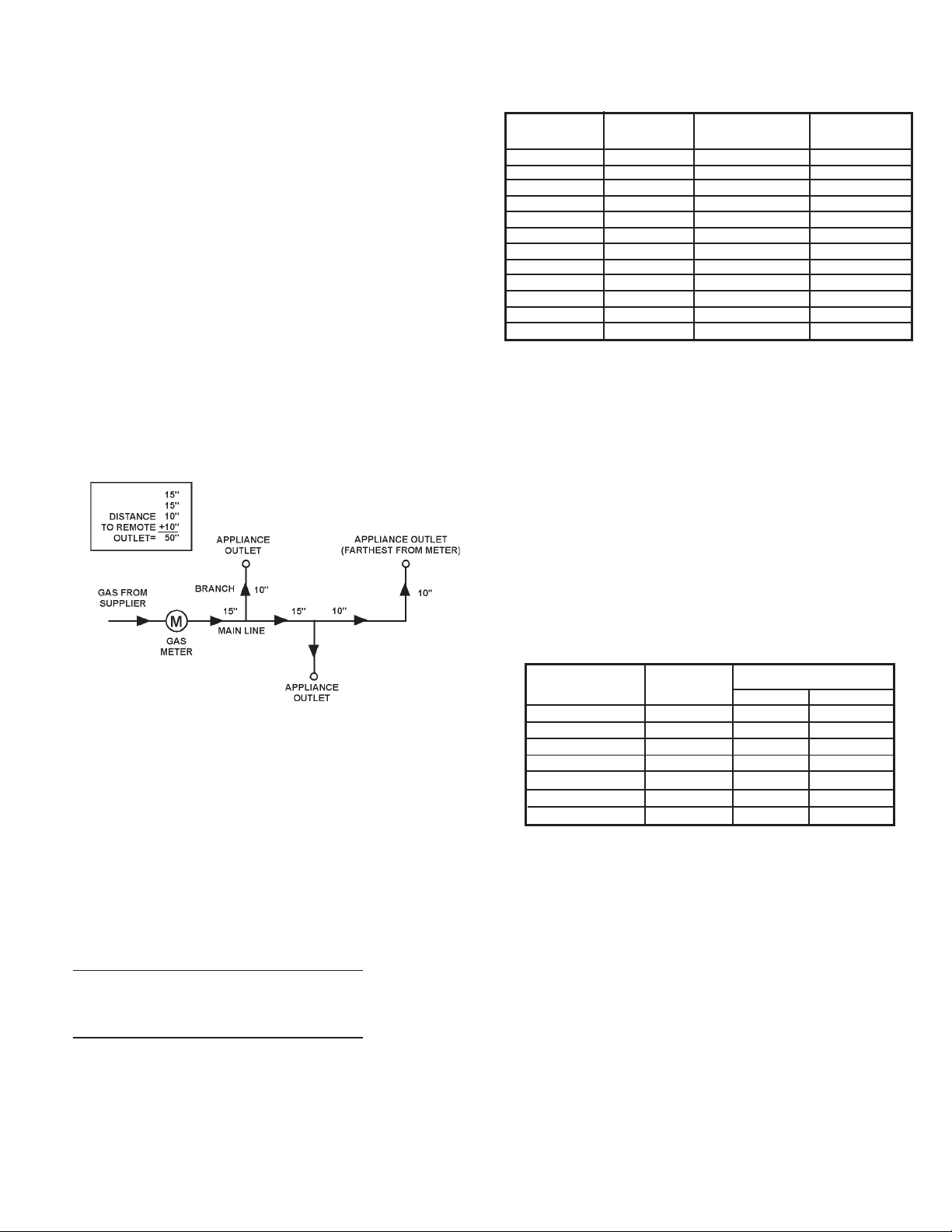
To determine the size of each section of gas piping in a system
within the range of table 6 proceed as follows:
• Determine the gas demand of each appliance to be attached
to the piping system. When table 6 is to be used to select the
piping size, calculate the gas demand in terms of cubic feet per
hour for each piping system outlet. The gas demand for an
appliance can be found by dividing its heat input rate by the
gas’s heating value.
• Obtain or determine the length of piping from the gas meter or
service regulator to the appliance(s).
1010
10
1010
Page 11
• In table 6, select the row showing the distance to the most
remote outlet or the next longer distance if the table does not
give the exact length. This is the only distance used in
determining the size of any section of gas piping. If the gravity
factor is to be applied, the values in the selected row of table 6
are multiplied by the appropriate multiplier from table 7.
• Total the gas demands of all appliances on the piping system.
Enter table 6, on the left hand side, at the row equal to or just
exceeding the distance to the most remote outlet. Select the
pipe size in the row with a capacity equal to or just exceeding
the total gas demand. This is the required main gas supply
line size leading away from the gas meter or regulator. To
determine the pipe size required for each branch outlet leading
away from the main supply line, determine the gas demand for
that outlet. Enter table 6 on the same row, and select the branch
pipe size for a capacity equal to or just exceeding the demand
at that outlet. The main line can be resized for a lesser capacity
after each branch outlet, since the gas demand is reduced.
Total the gas demands of all remaining appliances branching
off downstream on the main gas line. Re-enter table 6 in the
same row and select the appropriate pipe size with adequate
capacity. Repeat the branch sizing and main line re-sizing for
any remaining appliances in the system.
TABLE 7
MULTIPLIERS TO BE USED WITH T ABLE 6 WHEN APPL YING
THE GRA VITY FACTOR T O OTHER THAN .60 SPECIFIC GRAVITY
Specific Specific
Gravity Multiplier Gravity Multiplier
.35 1.31 1.00 .78
.40 1.23 1.10 .74
.45 1.16 1.20 .71
.50 1.10 1.30 .68
.55 1.04 1.40 .66
*.60 (Nat.) 1.00 *1.50 (Prop.) .63
.65 .96 1.60 .61
.70 .93 1.70 .59
.75 .90 1.80 .58
.80 .87 1.90 .56
.85 .84 *2.00 (Butane) .5 5
.90 .82 2.10 .54
*Use these correction factors if exact specific gravity of the gas is not
known.
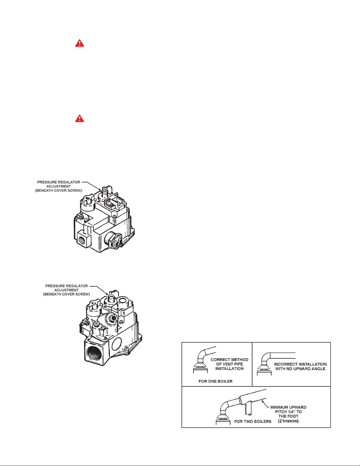
GAS PRESSURE REGULA TORS
The gas pressure regulator is included in the combination gas
valve, fig. 6, and is set to operate on the gas specified on the boiler
model and rating plate.
Periodically check main burner, fig. 41, and pilot flame, fig. 42, for
proper operation. This should be checked every six months.
EXAMPLE
Job Condition:
Determining the required gas pipe size for a system composed of
two HWB/HW-420 boilers and two HWB/HW-610 boilers to be
installed as a multiple group, 50 lineal feet from meter. Gas to be
used has a .60 specific gravity and heating value of 1,000 Btu per
cubic foot.
Solution:
2 HWB/HW-420 Boilers = 840,000 Btuh
2 HWB/HW-610 Boilers = 1,220,000 Btuh
Total Btuh Input = 2,060,000 Btuh
Do not subject the gas valve to inlet gas pressures of more than
14" W.C. (1/2 P.S.I.). If higher gas pressures are encountered, a
service regulator is necessary.
TABLE 8
CORRECT MANIFOLD PRESSURE FOR FULL
BOILER INPUT (IN INCHES OF WA TER COLUMN)
Model Rated Manifold Pressure
Number Input Natural Propane
HWB/HW-300 300,000 3.5 10.0
HWB/HW-399 399,000 3.2 9.5
HWB/HW-420 420,000 3.5 10.0
HWB/HW-520 520,000 3.5 10.0
HWB/HW-610 610,000 3.5 10.0
HW-670 Nat. 660,000 3.5
HW-670 Prop. 670,000 10.0
Adjustment, if required, is performed as follows:
1. Set primary system temperature control dial (thermostat) at
lowest setting so that boiler will not call for heat.
2. Attach a pressure gauge to the tapping in the control string
elbow.
3. Reset primary system temperature control dial (thermostat)
to highest setting. Main burner will now ignite.
Total Btuh Input = 2,060,000 Btuh = 2,060 cf/h
Btu per Cubic Foot of Gas 1,000
With a cubic foot per hour demand of 2,060 and with 50 lineal feet
of gas supply line, table 6 shows a pipe size of 3" (76mm) is
required.
NOTE: For other than .60 specific gravity, apply multiplier factor
as shown in table 7.
4. With main burner firing, adjust pressure, if necessary, by turning
pressure regulator adjusting screw with a screwdriver.
• Clockwise to increase pressure.
• Counterclockwise to decrease pressure.
5. Set primary system temperature control dial (thermostat) to
lowest setting.
6. Remove pressure gauge and replace sealing plug.
1111
11
1111
Page 12
7. Set primary system temperature control dial (thermostat) to
desired setting.
WARNING
DO NOT INCREASE GAS PRESSURE ABOVE THAT SPECIFIED
ON THE RATING PLATE, AS OVERFIRING WILL RESULT IN
DAMAGE TO THE BOILER, AS WELL AS INCREASED RISK OF
FIRE, SOOTING AND ASPHYXIA TION.
If gas pressure regulator cannot be adjusted to correct pressure
with sufficient gas pressure at the valve, replace with new gas
valve.
VENTING THE BOILER - STANDARD VENTING
Vent connectors serving appliances vented by natural draft shall
not be connected into any portion of mechanical draft systems
operating under positive pressure.
The minimum distance from adjacent public walkways, adjacent
buildings, openable windows and building openings shall not be
less than those values specified in the National Fuel Gas Code,
ANSI Z223.1 and/or CAN/CSA B149.1-00, Installation Codes;
Stack or chimney must be a minimum height of 12" (305mm)
above the annual snow fall to prevent blockage.
Building materials must not come in contact with combustion
products from stack or chimney, due to the degradating properties
of flue products.
WARNING
THE INSTRUCTIONS IN THIS SECTION ON VENTING THE
BOILER MUST BE FOLLOWED TO AVOID CHOKED COMBUSTION
OR RECIRCULATION OF FLUE GASES. SUCH CONDITIONS
CAUSE SOOTING OR RISKS OF FIRE AND ASPHYXIA TION.
TYPE B VENTING MAY BE USED WITH THESE BOILERS. ALL
LOCAL UTILITY REGULATIONS ON VENTING SHOULD BE
FOLLOWED.
ROBERTSHA W® 7000 DERHC
HWB/HW-300, 399,-420, -520, -610, -670 NATURAL GAS WITH I.I.D.
HW-300, -399, -420, -520, -670 LP GAS WITH I.I.D. U.S. ONLY
Flue products must have a minimum clearance of 4 feet (1.22m)
horizontally from, and in no case above or below, unless a 4-foot
(1.22m) horizontal distance is maintained, from electric meters,
gas meters, regulators and relief equipment.
The Canadian B149.1-00, Installation Code specifies a 6 foot
horizontal vent terminal clearance to gas and electric meters and
relief devices (this clearance is specified as 4 feet in the U.S.
under the National Fuel Gas Code, ANSI/Z223.1). Therefore
instruction provision 134.1-b19(d), which specifies compliance
with the 4 foot clearance, as applies in the U.S. only, and the
B149.1-00 Installation Code applies in Canada.
1. DRAFT HOOD
The draft hood furnished with this boiler must be installed without
alteration. Provision must be made if the boiler is installed in
confined space or a small boiler room to accommodate draft hood
spillage and avoid risks described above. The upper air opening
called for in the AIR REQUIREMENTS section of this manual is for
this purpose.
2. VENT CONNECTION
Size and install proper size vent pipe. Do not reduce pipe size to
less than that of the draft hood outlet.
Horizontal runs of vent pipe shall be securely supported by
adequately placed (approximately every 4 feet or 1 meter),
noncombustible hangers and/or slip joints suitable for the weight
and design of the materials employed to prevent sagging and to
maintain a minimum upward slope of 1/4" (21mm/m) per foot
from the boiler to the vent terminals, fig. 7. Dampers or other
obstructions must not be installed in the vent. Be sure that the vent
pipe does not extend beyond the inside wall of the chimney.
HWB/HW-300, 399,-420, -520, -610 SINGLE STAGE
ROBERTSHAW® 7000 ERHC (LP)
STANDING PILOT, CANADIAN ONLY
FIGURE 6
For boilers for connection to gas vents or chimneys, vent sizing,
installation and termination shall be in accordance with Part 7,
Venting of Equipment, of the National Fuel Gas Code, ANSI Z223.1,
or Section 7, Venting Systems and Air Supply for Appliances, of the
CAN/CSA B149.1-00, Installation Codes, or applicable provisions
of the local building codes.
1212
12
1212
VENT PIPE INST ALLA TION
FIGURE 7
® Robertshaw is a registered trademark of Fulton Controls Corp.
Page 13
Where a continuous or intermittent back draft is found to exist the
cause must be determined and corrected. A special vent cap may
be required. If the back draft cannot be corrected by the normal
methods or if a suitable draft cannot be obtained, a blower type
flue gas exhauster may be employed to ensure proper venting and
correct combustion if permitted by local codes.
WARNING
FAILURE TO CORRECT BACK DRAFTS WILL CAUSE AIR
CONTAMINA TION AND UNSAFE CONDITIONS.
Vent connectors serving appliances vented by natural draft shall
not be connected into any portion of mechanical draft systems
operating under positive pressure.
After it has been determined that each appliance remaining
connected to the common venting system properly vents when
tested as outlined above, return doors, windows, exhaust fans,
fireplace dampers and any other gas burning appliance to their
previous conditions of use.
Any improper operation of the common venting system should be
corrected so the installation conforms with the latest edition of
CAN/CGA B149.1-00 (latest edition). When resizing any portion of
the common venting system, the common venting system should
be resized to approach the minimum size as determined using
the appropriate tables in Appendix G in CAN/CSA B149.1-00.
4. MULTIPLE VENT T ABLE
3. CONNECTING BOILER TO A COMMON VENT
Do not connect the boiler to a common vent or chimney with solid
fuel burning equipment. This practice is prohibited by many local
building codes as is the practice of venting gas fired equipment to
the duct work of ventilation systems.
Where a separate vent connection is not available and the vent
pipe from the boiler must be connected to a common vent with oil
burning equipment, the vent pipe should enter the common vent
or chimney at a point ABOVE the flue pipe from the oil fired unit.
Where two or more appliances vent into a common vent connector
or manifold, the area of the common vent or vent connector should
at least equal the area of the largest vent connector plus 50% of
the areas of the additional draft hood outlets.
When removing a boiler from a system with a common vent, use
the following steps:
Be sure the other appliances connected to the common vent are
not in operation.
Seal any unused openings in the common venting system.
Visually inspect the venting system for proper size and horizontal
pitch and determine there is no blockage or restriction, leakage,
corrosion and other deficiencies which could cause an unsafe
condition.
Table 9 has been compiled to show the material sizes in a Type B
doublewall combined vent system. Refer to
CAN/CSA B149 .1-00 (latest edition), or the ASHRAE
Equipment Volume for further information.
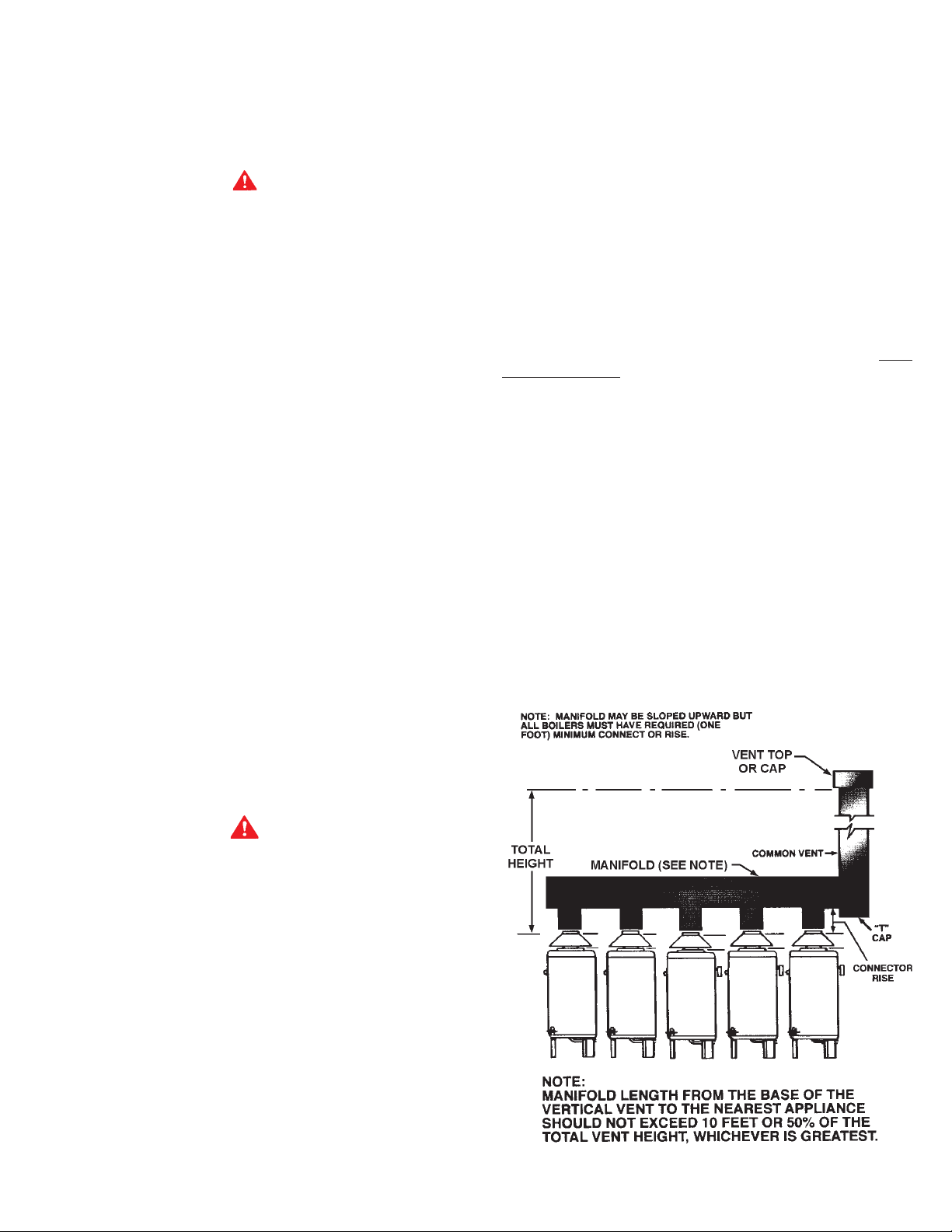
A combined vent system is one in which two or more boilers at one
level are attached to a common vent.
In order to use table 9, the connector rise and total vent height
must be known. Connector rise is vertical distance from the draft
hood outlet to the point where the manifold connection is made.
Total vent height is the least vertical distance from a draft hood
outlet to the top of the vent. Local codes or utility requirements
often govern termination height. ULC listed doublewall gas vents,
up through 24" (610mm) diameter, can be installed in heated and
unheated areas and can pass through floors, ceilings, partitions,
walls and roofs, provided the required one inch clearance is
observed. These vents should be installed in accordance with
CAN/CSA B149.1-00 (latest edition).
EXAMPLE SHOWING USE OF THE HWB/HW-610 COMBINED VENT
SIZING TABLE 9
1983
WARNING
Ensure sufficient supply and ventilation air . Under no circumstances
should the equipment room where the boiler is installed ever be
under negative pressure. Insufficient air supply can interfere with
combustion and ventilation of this boiler resulting in unsafe
conditions.
Insofar as is practical, close all building doors and windows and
all doors between the space in which the appliances remaining
connected to the common venting system are located and other
spaces of the building. Turn on clothes dryers and any appliance
not connected to the common venting system. Turn on any exhaust
fans, such as range hoods and bathroom exhausts, so they will
operate at maximum speed. Close fireplace dampers.
Place in operation the appliance being inspected. Follow the
lighting instructions. Adjust thermostat so appliance will operate
continuously.
Test for spillage at the draft hood relief opening after five minutes
of main burner operation. Use the flame of a match or candle.
1313
13
1313
FIGURE 8
Page 14
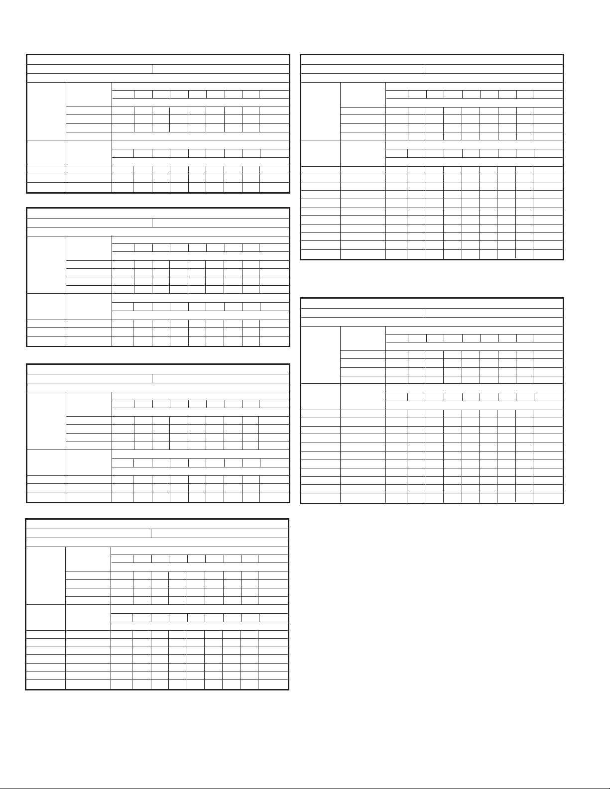
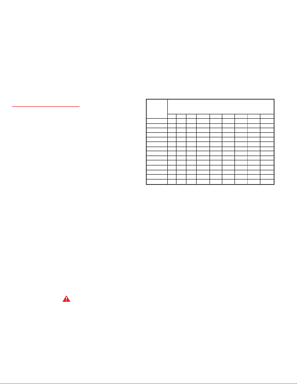
TABLE 9, COMBINED VENT SIZING T ABLES
Input: 300,000 Btuh Draft Hood Outlet 8"
MODEL HW/HWB-300 BOILER
Required Connector or Smoke Pipe Diameter
Connector Total Vent Height(Measured in Feet Above Draft Hood)
Rise in 10 15 20 30 40 50 60 80 100
Feet Connector Diameter (in Inches)
1 101010101010101010
2 101010101010101010
3 101010101010101010
4 or more
Number Total Total Vent Height(Measured in Feet Above Draft Hood)
if Units Input 10 15 20 30 40 50 60 80 100
Combined Btuh x 1000 Manifold and Common Vent Diameter (in Inches)*
2 600 14 12 12 12 10 10 10 10 10
3 900 16 14 14 14 12 12 12 12 12
4 1200 18 16 16 14 14 14 14 12 12
MODEL HW/HWB-399 BOILER
Input: 399,000 Btuh Draft Hood Outlet 10"
Required Connector or Smoke Pipe Diameter
Connector Total Vent Height(Measured in Feet Above Draft Hood)
Rise in 10 15 20 30 40 50 60 80 100
Feet Connector Diameter (in Inches)
1 121212121212121212
2 121212101010101010
3 121010101010101010
4 or more 10 10 10 10 10 10 10 10 10
Number Total Total Vent Height(Measured in Feet Above Draft Hood)
if Units Input 10 15 20 30 40 50 60 80 100
Combined Btuh x 1000 Manifold and Common Vent Diameter (in Inches)*
2 798 14 14 14 12 12 12 12 12 12
3 1197 18 16 16 14 14 14 14 14 12
4 1596 20 20 18 16 16 16 14 14 14
MODEL HW/HWB-420 BOILER
Input: 420,000 Btuh Draft Hood Outlet 10"
Required Connector or Smoke Pipe Diameter
Connector Total Vent Height(Measured in Feet Above Draft Hood)
Rise in 10 15 20 30 40 50 60 80 100
Feet Connector Diameter (in Inches)
1 121212121212121212
2 121212101010101010
3 121010101010101010
4 or more 10 10 10 10 10 10 10 10 10
Number Total Total Vent Height(Measured in Feet Above Draft Hood)
if Units Input 10 15 20 30 40 50 60 80 100
Combined Btuh x 1000 Manifold and Common Vent Diameter (in Inches)*
2 840 14 14 14 12 12 12 12 12 12
3 1260 18 16 16 14 14 14 14 14 12
4 1680 20 20 18 16 16 16 14 14 14
Input: 610,000 Btuh Draft Hood Outlet 12"
MODEL HW/HWB-610 BOILER
Required Connector or Smoke Pipe Diameter
Connector Total Vent Height(Measured in Feet Above Draft Hood)
Rise in 10 15 20 30 40 50 60 80 100
Feet Connector Diameter (in Inches)
1 161414141414141414
2 141414141412121212
3 141412121212121212
4 or more 12 12 12 12 12 12 12 12 12
Number Total Total Vent Height(Measured in Feet Above Draft Hood)
if Units Input 10 15 20 30 40 50 60 80 100
Combined Btuh x 1000 Manifold and Common Vent Diameter (in Inches)*
2 1220 18 18 16 16 14 14 14 14 14
3 1830 22 20 20 18 18 16 16 16 14
4 2440 26 24 22 20 20 18 18 18 16
5 3050 28 26 26 24 22 22 20 20 18
6 3660 32 28 28 26 24 24 22 22 20
7 4270 34 32 30 28 26 24 24 22 22
8 4880 36 34 32 30 28 26 26 24 24
9 5490 38 36 34 30 30 28 28 26 24
10 6100 40 38 36 32 30 30 28 26 26
1 1 6710 42 38 38 34 32 30 28 28 26
12 7320 44 42 38 36 34 32 32 30 28
MODEL HW/HWB-670 BOILER
Input: 660,000 or 670,000 Btuh Draft Hood Outlet 12"
Required Connector or Smoke Pipe Diameter
Connector Total Vent Height(Measured in Feet Above Draft Hood)
Rise in 10 15 20 30 40 50 60 80 100
Feet Connector Diameter (in Inches)
1 161414141414141414
2 141414141412121212
3 141412121212121212
4 or more 12 12 12 12 12 12 12 12 12
Number Total Total Vent Height(Measured in Feet Above Draft Hood)
if Units Input 10 15 20 30 40 50 60 80 100
Combined Btuh x 1000 Manifold and Common Vent Diameter (in Inches)*
2 1340 18 18 16 16 14 14 14 14 14
3 2010 22 20 20 18 18 16 16 16 14
4 2680 26 24 22 20 20 18 18 18 16
5 3350 28 26 26 24 22 22 20 20 18
6 4020 32 28 28 26 24 24 22 22 20
7 4690 34 32 30 28 26 24 24 22 22
8 5360 36 34 32 30 28 26 26 24 24
9 6030 38 36 34 30 30 28 28 26 24
10 6700 40 38 36 32 30 30 28 26 26
1 1 7370 42 38 38 34 32 30 28 28 26
12 8040 46 44 40 38 36 34 34 32 30
Input: 520,000 Btuh Draft Hood Outlet 10"
MODEL HW/HWB-520 BOILER
Required Connector or Smoke Pipe Diameter
Connector Total Vent Height(Measured in Feet Above Draft Hood)
Rise in 10 15 20 30 40 50 60 80 100
Feet Connector Diameter (in Inches)
1 141414121212121212
2 121212121212121212
3 121212121010101010
4 or more 12 12 12 12 10 10 10 10 10
Number Total Total Vent Height(Measured in Feet Above Draft Hood)
if Units Input 10 15 20 30 40 50 60 80 100
Combined Btuh x 1000 Manifold and Common Vent Diameter (in Inches)*
2 1040 16 16 14 14 14 14 12 12 12
3 1560 20 18 18 16 16 14 14 14 14
4 2080 22 22 20 18 18 18 16 16 14
5 2600 26 24 22 20 20 18 18 18 18
6 3120 28 26 24 22 22 20 20 18 18
7 3640 30 28 26 24 24 22 22 20 20
8 4160 32 30 28 26 24 24 22 22 20
Known: (5) model HWB/HW-610 boilers. (See illustration).
Connector rise - 2' (Note 1' is minimum). Total vent height
30'.
Problem: Determine diameter of connector, manifold and
common vent.
Procedure: Enter the top of the HWB/HW-610 table (total vent height)
at 30' and the side at 2' (connector rise). A 14" connector
diameter is indicated for each connector rise.
To determine the manifold and common vent size, enter this table
(total vent height) at 30 and the side at 5 boilers. A manifold
diameter of 24" (610mm) is indicated.
1414
14
1414
Page 15
VENTING MAINTENANCE - ST ANDARD VENTING
It is recommended that the heating surfaces and vent piping of
the appliance be checked every six months for dust, deterioration
and carbon deposits. Remove all soot or other obstructions from
chimney and flue which will retard free draft. Replace any
damaged or deteriorated parts of the venting system.
Qualified servicers should follow this procedure when the boiler’s
external heating surfaces and vent pipe need cleaning.
CAUTION
DO NOT USE A NYLON BRUSH OR OTHER STA TIC CREATING
MATERIAL TO CLEAN DUST AND CARBON DEPOSITS FROM
HEA TING SURFACES AND VENT.
SUCH DEPOSITS ARE FLAMMABLE AND MAY BE IGNITED BY
STATIC ELECTRICITY . USE A METAL BRUSH TO MINIMIZE THE
DANGER OF EXPLOSION.
1. Turn off the electrical power (main manual gas shutoff and
pilot valves, if applicable).
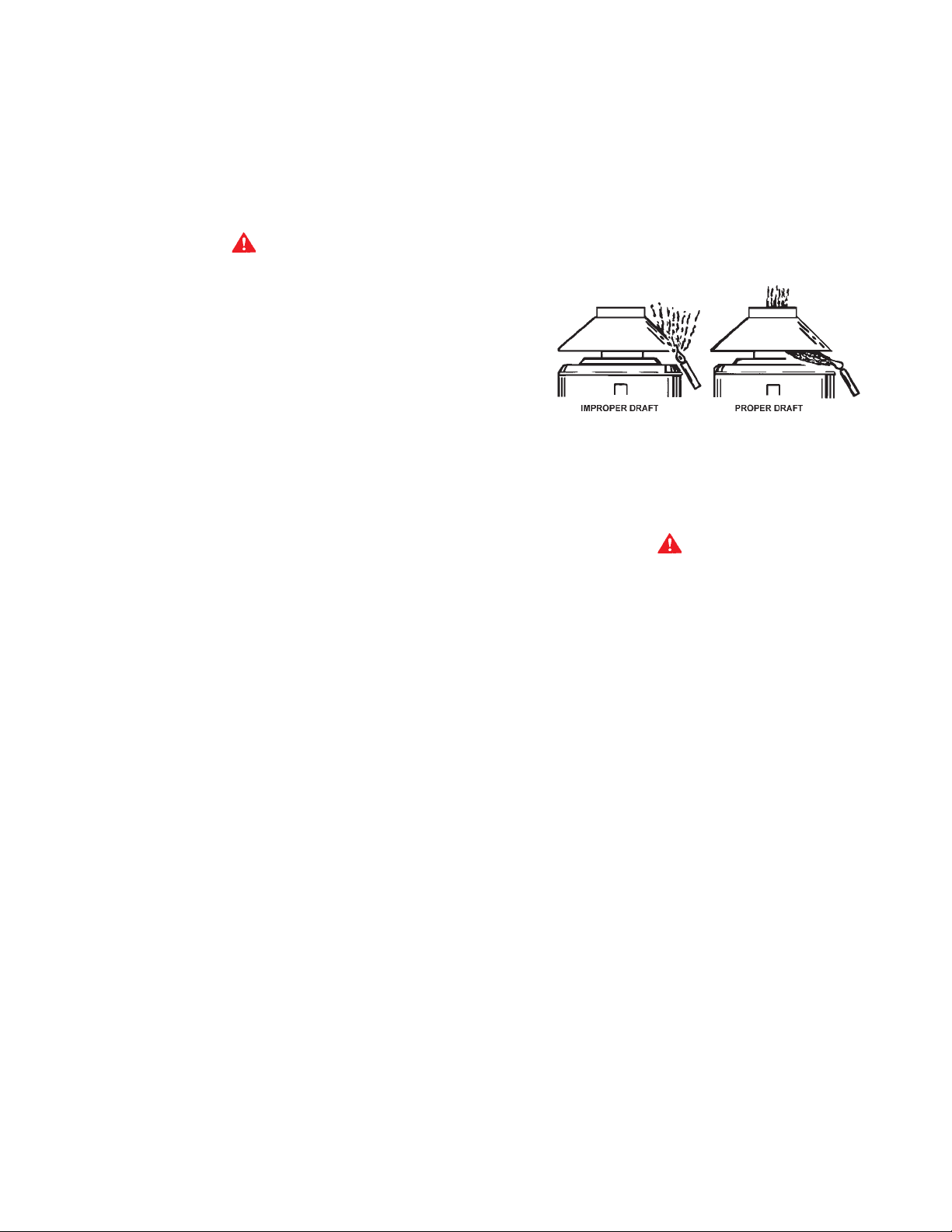
gas vent properly by passing a lighted match or taper around
the edge of the relief opening of the draft hood. If the chimney or
gas vent is drawing properly, the match flame will be drawn into
the draft hood. If not, the combustion products will tend to
extinguish this flame. IF THE COMBUSTION PRODUCTS ARE
ESCAPING FROM THE RELIEF OPENING OF THE DRAFT
HOOD, DO NOT OPERA TE THE EQUIPMENT UNTIL PROPER
ADJUSTMENT OR REPAIRS ARE MADE TO PROVIDE
ADEQUA TE DRAFT THROUGH THE CHIMNEY OR GAS VENT.”
D. Next, turn on all other fuel burning appliances within the same
room so they will operate at their full input.
Repeat step C above, checking the draft on each appliance.
Allow boiler parts and vent to cool before disassembly.
2. Remove the boiler draft diverter and vent pipe running to the
chimney.
• Check parts and chimney for obstructions and clean as
necessary.
3. Remove burner from boiler and other metal parts as required
to clean and vacuum the heat exchanger and combustion
coils.
• Refer to parts list supplied with this manual for
disassembly aid.
4. Reinstall the parts removed in steps 2 and 3.
• Be sure the vent pipe has a minimum upward pitch of one
quarter inch per foot of length (21mm/m) and is sealed as
necessary.
5. Restore electrical power and gas supply to boiler.
• Place boiler in operation by following the lighting
instructions in this manual.
• Check for gas leaks and proper boiler and vent operation.
VENTING - SIDEWALL
(OPTIONAL) POWER VENT SYSTEM
If you are installing the optional Power Vent Kit, refer to your
HWB/HW Power Vent Kit Inst allation Instructions for proper wiring
and installation procedures. Contact your local A.O. Smith
representative for details.
VENTING SYSTEM
HA VE VENTING SYSTEM CHECKED EVERY SIX MONTHS FOR
OBSTRUCTIONS AND/OR DETERIORA TION IN VENT PIPING.
FIGURE 9
SAFETY RELIEF V AL VES
Your local code authority may have other specific relief valve
requirements not covered below.
W ARNING
THE PURPOSE OF A SAFETY RELIEF VALVE IS TO AVOID
EXCESSIVE PRESSURE OR TEMPERATURE INTO THE STEAM
RANGE WHICH MAY CAUSE SCALDING AT FIXTURES, TANK
EXPLOSION, SYSTEM OR BOILER DAMAGE.
TO AVOID SCALDING OR WATER DAMAGE A DRAIN LINE MUST
BE CONNECTED TO A RELIEF VALVE TO DIRECT DISCHARGE
TO A SAFE LOCATION. A DRAIN LINE MUST NOT BE REDUCED
FROM THE SIZE OF THE VALVE OUTLET AND IT MUST NOT
CONT AIN ANY V ALVES BETWEEN THE BOILER AND THE RELIEF
VAL VE OR THE RELIEF V AL VE AND THE DRAIN EXIT. IN ADDITION,
THERE SHOULD NOT BE ANY RESTRICTIONS IN A DRAIN LINE
NOR SHOULD IT BE ROUTED THROUGH AREAS WHERE
FREEZING CONDITIONS MIGHT OCCUR. DO NOT THREAD OR
CAP THE DRAIN LINE EXIT . RESTRICTING OR BLOCKING A DRAIN
LINE WILL DEFEAT THE PURPOSE OF THE RELIEF VALVE AND
MAY CREATE AN UNSAFE CONDITION. INSTALL A DRAIN LINE
WITH A DOWNWARD SLOPE SUCH THA T IT NA TURALL Y DRAINS
ITSELF.
If any safety relief valve is replaced, the replacement valve must
comply with the latest version of the ASME Boiler and Pressure
Vessel Code, Section IV or CSA B51, as applicable. Select a relief
valve with a discharge NOT less than the boiler input, and a pressure
rating NOT exceeding the working pressure of any component in
the system.
A. Insofar as is practical, close all doors, windows and air inlets
to the building. Turn on all exhaust fans (range hood,
bathroom exhaust, etc.) so they will operate at their maximum
speed. Close fireplace dampers.
B. After allowing appliance to operate for five minutes, test for
spillage at the draft hood relief opening.
C. “CHECKING THE DRAFT. Operate vent connected gas
utilization equipment for several minutes and check to see
that the combustion products are going up the chimney or
A. O. Smith supplies Canadian HW boilers for hot water supply
systems with a 125 psi pressure relief valve. This valve must be
installed in the water outlet as near to the boiler as possible.
A. O. Smith United States HW and Canadian HWB boilers for space
heating are shipped with a 50 psi pressure relief valve. This valve
must be installed in the water outlet as near to the boiler as possible.
An ASME rated temperature and pressure relief valve must be
installed on each and every water storage tank in a hot water supply
system.
1515
15
1515
Page 16

The storage tank temperature and pressure (T & P) relief valve
must comply with the applicable construction provisions of the
Standard for Relief Valves and Automatic Gas Shutoff Devices for
Hot Water Supply Systems, Z21.22 and/or CAN1-4.4. The T & P
valve must be of the automatic reset type and not embody a
single-use type fusible plug, cartridge or linkage.
The T & P relief valve should have a maximum temperature rating
0
of 100
C (2100F), a pressure rating NOT exceeding the lowest
rated working pressure of any system component, and a discharge
capacity exceeding the total input of the water boilers supplying
water to the storage tank.
Locate the T & P relief valve (a) in the top of the storage tank, or (b)
in the side of the tank on centerline within the upper 6 inches from
the top of the tank. See figures 20 to 31. Tapping shall be threaded
in accordance with the latest version of the Standard for Pipe
Threads, General Purpose (inch), ANSI/ASME B1.20.1
The boiler, when installed, must be electrically bonded to ground
in accordance with the requirements of the authority having
jurisdiction or, in the absence of such requirements, with the
National Electrical Code, ANSI/NFPA 70 and/or the Canadian
Electrical Code Part 1, CSA C22.1, Electrical Code.
STRICT ADHERENCE TO PIPING AND WIRING DIAGRAMS IS
REQUIRED TO PREVENT CONSTANT PUMP OPERATION WHEN
SYSTEM TEMPERA TURE CONTROL IS SA TISFIED. OTHERWISE
THE WARRANTY IS VOID AS STIPULATED IN THE LIMITED
WARRANTY ON THE INSTRUCTIONS MANUAL.
The electrical connections must be made so that the circulator will
operate before the gas valve opens. At no time may the controlling
system allow the burner to fire when there is no water flow through
the boilers.
Refer to the diagrams in fig’s. 10 thru 11C for proper wiring
sequence with conventional single boiler installations.
Mark location with a Class lll label.
See ANSI Z21.10.1, Part 1, MARKING, See CAN/CSA B149.1-00.
WIRING CONNECTIONS
CAUTION
LABEL ALL WIRES PRIOR TO DISCONNECTION WHEN
SERVICING CONTROLS. WIRING ERRORS CAN CAUSE
IMPROPER AND DANGEROUS OPERA TION.
VERIFY PROPER OPERA TION AFTER SERVICING.
1. CONVENTIONAL INST ALLATIONS
ALL ELECTRICAL WORK MUST BE INST ALLED IN ACCORDANCE
WITH NATIONAL ELECTRICAL CODE, ANSI/NFP A 70 AND/OR THE
CANADIAN ELECTRICAL CODE, P ART 1, CSA C22.1, ELECTRICAL
CODE AND MUST CONFORM TO LOCAL REGULATIONS.
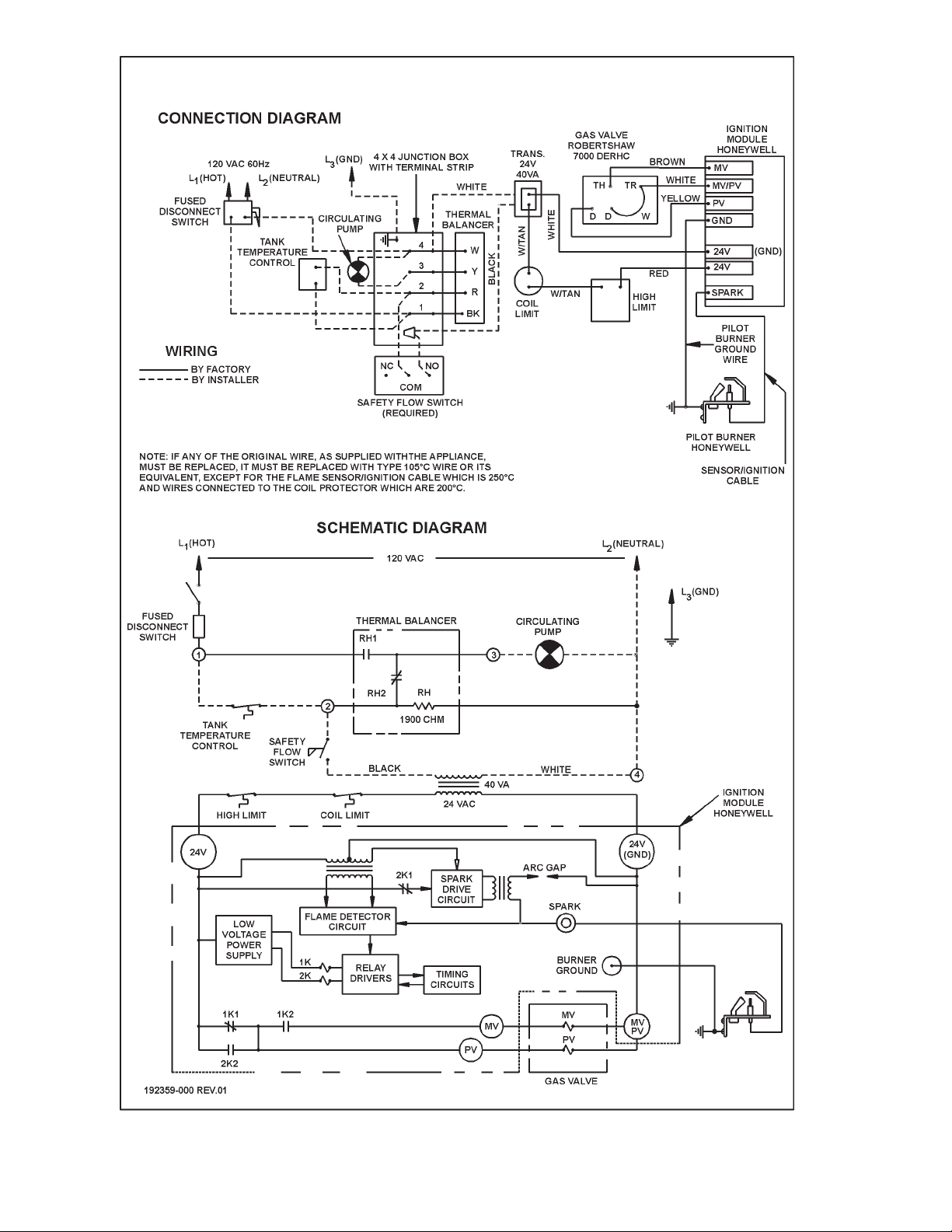
The THERMAL BALANCER shown is factory included by
A. O. Smith as part no. 98190. This device serves as a pump
shutdown delay switch to balance the rising boiler water
temperature to system temperature before the pump stops.
Overshooting of boiler temperature is prevented and stack loss
after shutdown is negligible.
WARNING
AN ELECTRICAL GROUND IS REQUIRED TO REDUCE RISK OF
ELECTRIC SHOCK OR POSSIBLE ELECTROCUTION. Make the
ground connection to the screw provided in the electrical supply
junction box on the boiler.
IF ANY OF THE ORIGINAL WIRE, AS SUPPLIED WITH THE
APPLIANCE, MUST BE REPLACED, IT MUST BE REPLACED WITH
TYPE 105
SENSOR AND IGNITION CABLE WHICH ARE 2500C AND WIRES
CONNECTED TO THE COIL PROTECTOR WHICH ARE 2000C.
0
C WIRE OR ITS EQUIVALENT , EXCEPT FOR THE FLAME
1616
16
1616
Page 17
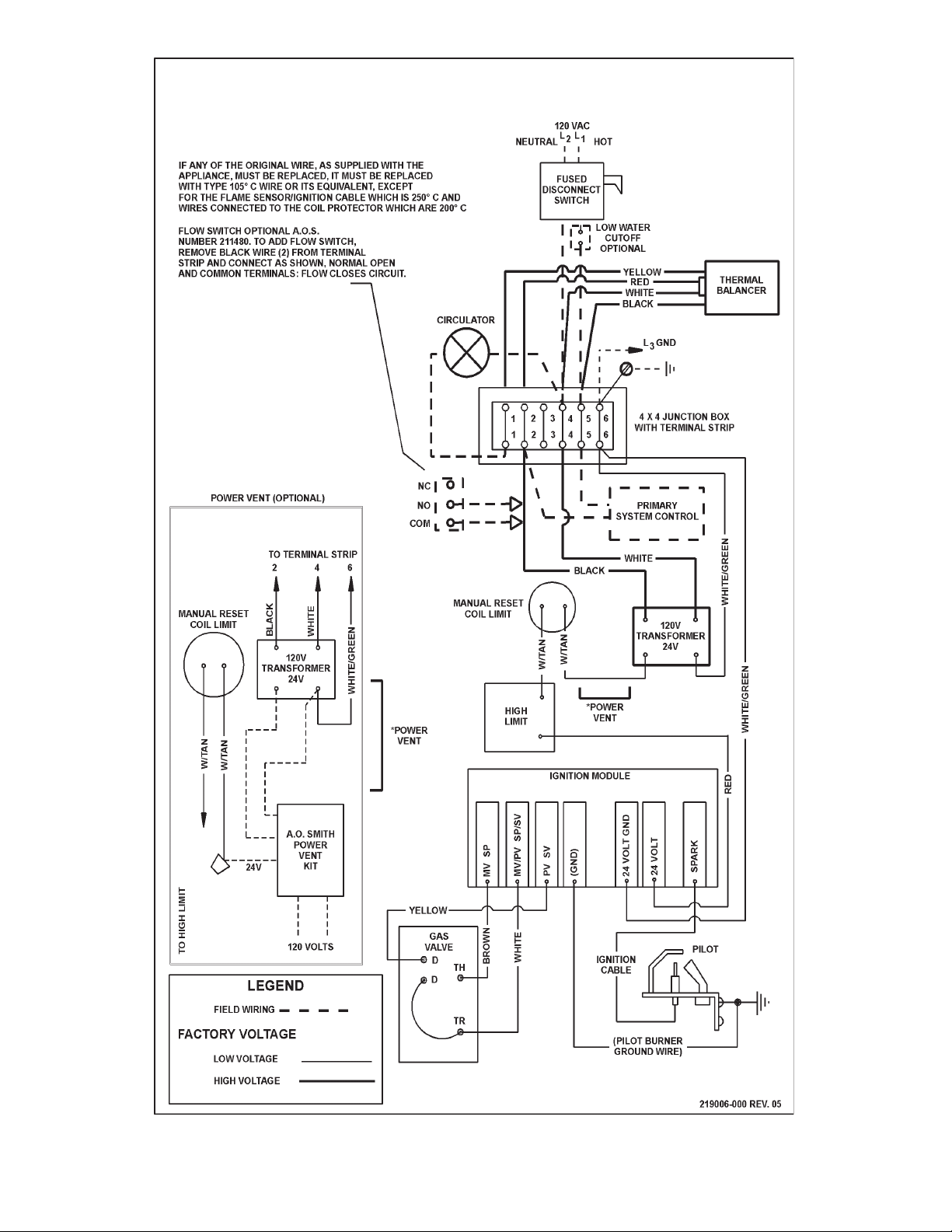
CONNECTION DIAGRAM
HWB & HW-300, -399, -420, -500 & -610
(NATURAL GAS)
SINGLE ST AGE I.I.D. - ROBERTSHAW® GAS V ALVE
HWB & HW-300, -399, -420, -520, -610 (NATURAL GAS ONL Y) - CANADIAN MODELS
® Robertshaw is a registered trademark of Fulton Controls Corp.
FIGURE 10
1717
17
1717
Page 18
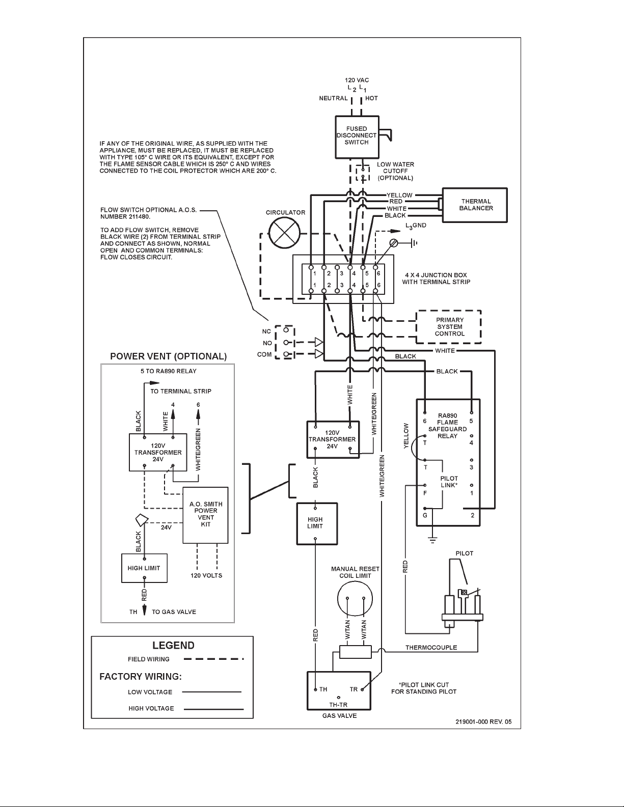
CONNECTION DIAGRAM
HWB, HW-420,-520, -610
(PROP ANE GAS)
SINGLE STAGE PROP ANE - ROBERTSHAW GAS V AL VE
24 VOL T -HW, HWB-420, -520, -610 CANADIAN MODELS
FIGURE 11
1818
18
1818
Page 19
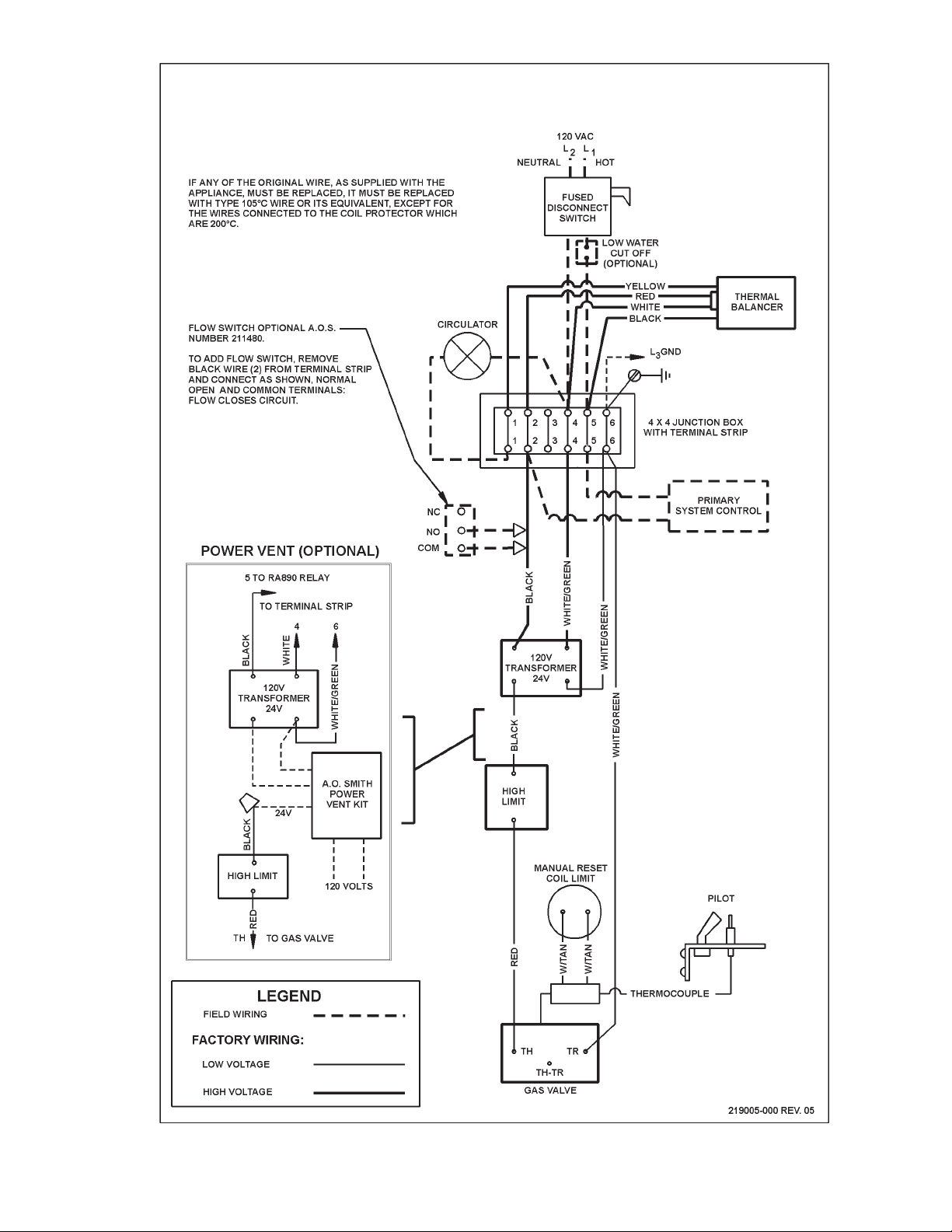
CONNECTION DIAGRAM HWB & HW 300, 399
(PROP ANE GAS)
FIGURE 13
SINGLE STAGE PROP ANE ROBERTSHA W GAS V ALVE
24 VOLT - HWB, HW -300, 399 CANADIAN MODELS
FIGURE 11A
1919
19
1919
Page 20
HW-300, HW-399, HW-420, HW-500 & HW-670
(NA TURAL GAS)
SINGLE ST AGE I.I.D. - ROBERTSHAW GAS V ALVE
HW-300, -399, -420, -520 & 670 (NA TURAL GAS ONL Y) - U.S. MODELS
FIGURE 11B
2020
20
2020
Page 21

HW-300, HW-399, HW-420, HW-500 & HW-670
(PROP ANE GAS)
FIGURE 12
SINGLE ST AGE I.I.D. - ROBERTSHAW GAS V ALVE
HW-300, -399, -420, -520 & 670 (PROP ANE GAS ONL Y) - U.S. MODELS
FIGURE 11C
2121
21
2121
Page 22

TYPICAL WIRING DIAGRAM (IID NATURAL GAS) FOR SINGLE BOILER LINEAR-TEMP® INSTALLA TION FOR CANADIAN MODELS
FIGURE 12
LINEAR-TEMP INSTALLA TIONS
2.
Control for these systems is decided mainly by the type of building
system controlling that is desired. A single boiler installation might
be controlled directly from space temperature thermostat(s).
Multiple boiler installations are more effective when the boilers
are sequenced in and out of operation by some form of main water
temperature controller. With one to three boilers, individual controls
set at progressive temperatures may be used. For more than
three or four boilers, a step controller is recommended.
Individual boiler controls, or the separate stages of a step controller ,
should fire a boiler and also start the boiler loop circulator whenever
the first boiler of a group supplied by that boiler loop is fired. Some
large installations may require the firing of more than one boiler
per stage.
The system or primary circulator may or may not be controlled by
the boiler sequencer. When this pump is operated through the
first switch of any type of step controller, care should be taken to
determine if a motor starter is needed due to insufficient switch
capacity.
If the primary pump is controlled by a manual switch or any other
controllers, the electric current supply to the boiler group should
be through the primary pump controller. The fast response of
A. O. Smith boilers eliminates any need to maintain boiler
temperature when the system is satisfied. Wiring should always
prevent firing of boiler(s) when there is no water flow in the mains.
Installation diagrams show flow switches in the outlet piping from
each boiler as good protection against any boiler being fired when
the boiler loop circulator is not in operation. These flow switches
will also serve as protection if there is a loss of water.
Outdoor vent systems will normally require an automatic shutdown
control if there is a continuous recirculating main and/or if the
entire building is not under control of space temperature
thermostats. A single bulb outdoor sensing control will prevent
overheating of halls, stairways or other uncontrolled areas. There
are occasions when outdoor temperatures are temporarily too
warm for even a moderate amount of heating in these areas.
Space temperature controlling can be varied to meet the building
requirements. Either the single thermostat, as shown, or multiple
zone thermostats should control a common relay. This relay
controls electric power to the system primary circulator and to the
main water temperature controller. This provides for water
movement in the system before the main temperature controller
can start the secondary circulating pump or fire the boiler.
Figure 12 shows a typical wiring diagram for a single boiler space
heating installation. The boiler may be controlled by a main
temperature controller as shown or may include outdoor reset if
desired. The boiler shown is the model HW-610 with single stage
firing, typical of HW models.
Figure 13 shows a layout for various choices of controls often
found in commercial heating. These layouts are not intended to
be wiring diagrams and only show the relation of one device to
another in the system.
Figure 13 is a typical layout of controls for two boilers with one
circulator and including optional outdoor reset and thermal
balancer. If a secondary circulator is used with each boiler,
arrangement for boiler no. 2 will be as shown for boiler no. 1.
Commercial size installations are always best when designed to
individual building requirements.
The layout in figure 13 is typical of many combination possibilities
to meet the requirements of different buildings. Brand names of
controls shown are suggestions and not directly related to any
particular type of system. THESE LAYOUTS ARE NOT WIRING
DIAGRAMS.
A.O. Smith offers accessory Sequencing Control Panels;
TEK-252 for 2 Stage Boiler Control
TEK-254 for 4 Stage Boiler Control
TEK-258 for 8 stage Boiler Control
For more information contact A.O. Smith Product Service
Department at 1-800-433-2545.
2222
22
2222
Page 23

NOTE:
1. Building temperature controls supply electric power to building
circulator.
2. Main flow switch proves main water flow before energizing sequencing
and resetting controls.
CONTROL APPLICA TION DIAGRAM - TWO BOILER LINEAR-TEMP® INST ALLA TION WITH TWO CIRCULATOR S
FIGURE 13
3. Outdoor thermostat required if building controls do not provide automatic
shutdown of reset controls during warm weather.
Boilers and Secondary Circulator are Controlled by
• Dual Bulb, Dual Switch Controller
Staging and Outdoor Reset of Main Water Temperature
NOTE:
1. Building temperature controls supply electric power to building
circulator.
2. Main flow switch proves main water flow before energizing sequencing
and resetting controls.
3. Outdoor thermostat required if building controls do not provide automatic
shutdown of reset controls during warm weather.
CONTROL APPLICA TION DIAGRAM - THREE BOILER LINEAR-TEMP® INST ALLA TION WITH THREE CIRCULATORS
FIGURE 14
2323
23
2323
Boilers and Secondary Circulator are Controlled by
• One Dual Bulb, Dual Switch Mechanical Controller and
• One Dual Bulb, single Switch Mechanical Controller
Sequencing and Outdoor Reset of Main Water Temperature.
Page 24

NOTE:
1. Building temperature controls supply electric
power to building circulator.
2. Main flow switch proves main water flow before
energizing sequencing and resetting controls.
3. Outdoor thermostat required if building controls
do not provide automatic shutdown of reset
controls during warm weather.
Boilers and Secondary
Circulator are Controlled by
Dual Bulb, Dual Switch Controller
Staging and Outdoor Reset of
Main Water Temperature
CONTROL APPLICA TION DIAGRAM - FOUR BOILER LINEAR-TEMP® INST ALLATION WITH TWO CIRCULATORS
NOTE:
1. Building temperature controls
supply electric power to
building circulator.
2. Main flow switch proves main
water flow before energizing
sequencing and resetting
controls.
3. Outdoor thermostat required if
building controls do not provide
automatic shutdown of reset
controls during warm weather.
4. Should motor load exceed 7.5
AMPS,
use relays or motor starters.
5. In absence of main flow switch
and low water cutoff, jumper
"A" and "B" together.
FIGURE 15
Boilers and Secondary Circulator areControlled by Dual Bulb, Dual Switch Controller Staging and Outdoor Reset of Main Water Temperature
CONTROL APPLICA TION DIAGRAM - EIGHT BOILER LINEAR-TEMP® INST ALLA TION WITH INDIVIDUAL CIRCULA TORS
FIGURE 16
2424
24
2424
Page 25

CER-TEMP 80 - 1 UNIT INSTALLATION - FOR HOT WATER SUPPLY APPLICATION
CANADIAN MODELS, JUNCTION BOX W/6 TERMINALS
FIGURE 17
CER-TEMP 80 - 1 UNIT INSTALLATION - FOR HOT WATER SUPPLY APPLICATION
U.S. MODELS, JUCNTION BOX W/4 TERMINALS
FIGURE 18
FIGURE 19
2525
25
2525
Page 26

CER-TEMP 80 - 2 OR 3 UNIT INSTALLATION - FOR HOT WATER SUPPLY APPLICATION
CANADIAN MODELS, JUNCTION BOX W/6 TERMINALS
FIGURE 20
2626
26
2626
Page 27

SCHEMATIC
CANADIAN MODELS, JUNCTION BOX W/6 TERMINALS
FIGURE 21
2727
27
2727
Page 28

CER-TEMP 80 - 2 OR 3 UNIT INSTALLATION CONNECTION DIAGRAM
(FOR HOT WATER SUPPLY APPLICATION)
U.S. MODELS, JUNCTION BOX W/4 TERMINALS
FIGURE 22
2828
28
2828
Page 29

CER-TEMP 80 - 2 OR 3 UNIT INSTALLATION SCHEMATIC DIAGRAM
(FOR HOT WATER SUPPLY APPLICATION)
U.S. MODELS, JUNCTION BOX W/4 TERMINALS
FIGURE 23
2929
29
2929
Page 30

BOOSTER - RECOVERY WIRING DIAGRAM
CANADIAN MODELS, JUNCTION BOX W/6 TERMINALS
FIGURE 24
SHURE-TEMP BOOSTER - RECOVERY WIRING DIAGRAM
(TWO TEMPERATURE SYSTEM)
CANADIAN MODELS, JUNCTION BOX W/6 TERMINALS
FIGURE 25
3030
30
3030
Page 31

BOOSTER - RECOVERY WIRING DIAGRAM
U.S. MODELS, JUNCTION BOX W/4 TERMINALS
FIGURE 26
SHURE - TEMP BOOSTER - RECOVER Y WIRING DIAGRAM
TWO-TEMPERATURE SYSTEM
U.S. MODELS, JUNCTION BOX W/4 TERMINALS
FIGURE 27
3131
31
3131
Page 32

WA TER LINE CONNECTIONS
T ANK TEMPERA TURE CONTROL
This section provides detailed installation diagrams for typical
methods of application for the unit using a Cer-Temp 80 Recovery
System (for one temperature water), and either Booster-Recovery
or the Shure-Temp Booster-Recovery System (for two temperature
water).
These diagrams will serve to provide the installer with a reference
for the materials and methods of piping necessary for installation.
It is essential that all water and gas piping, vent connections,
electrical wiring, and check and flow regulating valves be installed
as shown on the diagrams.
Consult the installation diagrams for appropriate locations to install
the safety flow switch(es), drain valves, thermometers, relief valves
and the circulating pump(s). Apply suitable pipe thread sealing
compounds to only the male threads of parts to be connected.
If any of these parts are being replaced in a functioning system,
remember to shut off the manual gas and control valve(s) and
close off the water inlet(s). Open a nearby faucet to relieve pressure
and/or drain the boiler or system before attempting to install the
new parts.
Check the diagrams thoroughly before starting installation to avoid
errors and minimize time and materials cost.
If the system is to be filled with water for testing or other purposes
during cold weather and before actual operation, care must be
taken to prevent a downdraft entering the boiler or freezing air from
contacting the system. Failure to do so may cause the water in the
system to freeze with resulting damage to the system. Damage
due to freezing is not covered by the warranty.
This equipment must be protected against loss of water or loss of
water flow by the installation of a safety flow switch in the outlet
piping from the boiler. Piping and wiring diagrams show the
application of the accessory package for this purpose.
HARD WA TER
Where hard water conditions exist, water softening or the threshold
type of water treatment is recommended. This will protect the
dishwashers, coffee urns, water boilers, water piping and other
equipment. When water softening or water treatment is not
practical, a comparatively easy method of periodic lime removal
from the boiler may be employed by installing gate valves, drain
valve and acid fill opening as shown in CLEANING AND FLUSHING
section of this manual.
The water temperature in the storage tank is controlled by the Tank
Temperature Control. The sensing element is mounted inside
the hot water storage tank, see fig's. 31-38.
DANGER
HOT WATER TEMPERATURES REQUIRED FOR AUTOMATIC
DISHWASHER AND LAUNDRY USE CAN CAUSE SCALD BURNS
RESULTING IN SERIOUS PERSONAL INJURY AND/OR DEATH.
THE TEMPERATURE A T WHICH INJURY OCCURS V ARIES WITH
THE PERSON’S AGE AND TIME OF EXPOSURE. THE SLOWER
RESPONSE TIME OF CHILDREN, AGED OR DISABLED
PERSONS INCREASES THE HAZARDS TO THEM. NEVER ALLOW
SMALL CHILDREN TO USE A HOT WATER TAP, OR TO DRAW
THEIR OWN BATH W ATER. NEVER LEA V E A CHILD OR DISABLED
PERSON UNATTENDED IN A BATHTUB OR SHOWER.
The tank temperature control is adjustable from 100°F (37.7°C) to
220°F (104.4°C). It is recommended that lower water temperatures
be used to avoid the risk of scalding. It is further recommended, in
all cases, that the water temperature be set for the lowest
temperature which satisfies the user’s hot water needs. This will
also provide the most energy efficient operation of the water heater
and minimize scale formation.
THE WA TER HEA TER SHOULD BE LOCA TED IN AN AREA WHERE
THE GENERAL PUBLIC DOES NOT HAVE ACCESS TO SET
TEMPERATURES. SETTING THE WATER TEMPERATURE AT
120°F (49°C) WILL REDUCE THE RISK OF SCALDS. Some states
or provinces require settings at specific lower temperatures. Below
you will find listed the approximate time-to-burn relationship for
normal adult skin. Valves for reducing point-of-use temperature by
mixing cold and hot water are available. Also available are
inexpensive devices that attach to faucets to limit hot water
temperatures. Contact a licensed plumber or the local plumbing
authority.
DET AIL OF T ANK FITTING USED WITH MODIFIED RECOVERY
AND BOOSTER RECOVERY PIPING DIAGRAMS
FIGURE 28
3232
32
3232
Page 33

Temperature Time to Produce 2nd & 3rd
Setting Degree Burns on Adult Skin
OVER: 170°F (77°C) Nearly instantaneous
160°F (71°C) About 1/2 second
150°F (65°C) About 1-1/2 seconds
140°F (60°C) Less than 5 seconds
130°F (54°C) About 30 seconds
120°F (49°C) More than 5 minutes
USE ANTI-SCALD VALVE(S) in the hot water system to reduce the
risks of scalds at points of use such as lavatories, sinks and
bathing facilities.
A float type or an electronic probe type low water cutoff may be
used. The manufacturer's installation instructions must be followed.
THERMOMETERS
Thermometers should be obtained and field installed as shown in
the installation diagrams.
Thermometers are installed in the system as a means of detecting
a possible liming condition in the boiler. An increase of 3°C (5°F)
over the normal temperature rise through the boiler is an indication
that lime is present. The term "temperature rise" designates the
difference between the boiler inlet and outlet water temperature.
A change in water temperature in the storage tank lower than the
Tank Temperature Control setting will cause the sensor to close
its contacts and consequently energize the boiler.
If the Tank Temperature Control is out of calibration, replace it with
a new one; do not attempt to fix this control.
WARNING
SHOULD OVERHEA TING OCCUR OR THE GAS SUPPL Y F AIL T O
SHUT OFF, TURN OFF THE MANUAL GAS CONTROL V ALVE TO
THE APPLIANCE.
LOW WA TER CUTOFF
A low water cutoff is a safety device which is installed in the boiler
piping to prevent the boiler from firing in the event of inadequate
water levels in the boiler system.
Where required by local code, this optional device is to be installed
in the boiler piping at a level above that of the heat exchanger.
An increase of 3°C (5°F) above the recorded temperature rise may
signify a liming condition in the coils or heat exchanger. Refer to
CLEANING AND FLUSHING section of this manual for deliming
instructions.
Record temperature rise at initial start-up for future reference.
DRAIN V AL VE (Not Supplied)
A drain valve must be obtained and installed on each boiler and
tank for draining purposes, see installation diagrams in this
manual.
CLOSED W ATER SYSTEM
This boiler should not be installed in a closed water system without
taking steps to reduce excessive system pressure due to thermal
expansion. Contact the water supplier or local plumbing inspector
on how to control this situation.
3333
33
3333
Page 34

ONE HW-300, HW-399, HW-420, HW-520, HW-610 OR ONE HW-670 UP-FLOW MODEL
COMMERCIAL BOILER WITH VERTICAL T ANK
TEMPERATURE SETTING SHOULD NOT EXCEED SAFE USE
DANGER
TEMPERATURE AT FIXTURES. SEE TANK TEMPERATURE
CONTROL WARNING ON PAGE 32. IF HIGHER PREHEAT
TEMPERATURES ARE NECESSARY TO OBTAIN ADEQUATE
BOOSTER OUTPUT , ADD AN ANTI-SCALD V ALVE FOR HOT
WATER SUPPLIED TO FIXTURES.
IMPORTANT
THE INSTALLA TION OF SAFETY FLOW SWITCH AS SHOWN
IS REQUIRED TO PROTECT THE BOILER IN CASE OF WA TER
SERVICE INTERRUPTION OR CIRCULAT OR F AILURE (A.O.
SMITH PKG. NO. 211480).
+ PIPING AND FITTINGS BETWEEN GATE VALVES AND
BOILERS SHOULD BE BRASS OR BRONZE. OTHER
PIPING SHOULD CONFORM TO LOCAL CODES.
GATE VA LVES ARE SHOWN FOR SERVICING BOILER.
HOWEVER, LOCAL CODES SHALL GOVERN THEIR USAGE.
* PRESSURE RELIEF VALVE RATING SHOULD NOT
EXCEED PRESSURE CAPACITY OF A NY COMPONENT
IN THE SYSTEM.
** INSTALL THERMOMETER AND PRESSURE RELIEF IN
OPENINGS PROVIDED ON HW-520, HW-610 &
HW-670.
USE THIS TABLE FOR CORRECT
PUMP AND W A TER PIPE SIZE
Minimum B & G *Armstrong
Model Pipe Size Pump Pump
Number (Inches) Size Size
HW-300 1-1/4" 125 S-25 1-1/4"
HW-399 1-1/2" 1-1/2" HV H-32 1-1/2"
HW-420 1-1/2" 1-1/2" HV H-32 1-1/2"
HW-520 1-1/2" 1-1/2" HV H-32 1-1/2"
HW-610/670 2" 2" S-35
*Assumes 50 equivalent feet pf piping or less.
WIRING - FIGURES 17, 18, 19
INSTALL IN ACCORDANCE
WITH ALL LOCAL CODES
FIGURE 29
3434
34
3434
Page 35

ONE HW-300, HW-399, HW-420, HW-520, HW-610 OR ONE HW-670 UP-FLOW MODEL
COMMERCIAL BOILER WITH HORIZONT AL T ANK
IMPORTANT
THE INSTALLA TION OF SAFETY FLOW SWITCH AS SHOWN IS
REQUIRED TO PROTECT THE BOILER IN CASE OF WATER
SERVICE INTERRUPTION OR CIRCULATOR FAILURE
(A.O. SMITH PKG. NO. 211480).
+ PIPING AND FITTINGS BETWEEN GATE VALVES AND
BOILERS SHOULD BE BRASS OR BRONZE. OTHER
PIPING SHOULD CONFORM TO LOCAL CODES.
GATE VALVES ARE SHOWN FOR SERVICING BOILER.
HOWEVER, LOCAL CODES SHALL GOVERN THEIR USAGE.
* PRESSURE RELIEF VALVE RA TING SHOULD NOT EXCEED
PRESSURE CAPACITY OF ANY COMPONENT IN THE
SYSTEM.
** INSTALL THERMOMETER AND PRESSURE RELIEF IN
OPENINGS PROVIDED ON HW-520, HW-610 & HW-670.
TEMPERATURE SETTING SHOULD NOT EXCEED SAFE USE
DANGER
TEMPERATURE AT FIXTURES. SEE TANK TEMPERATURE
CONTROL WARNING ON PAGE 32. IF HIGHER PREHEAT
TEMPERATURES ARE NECESSARY TO OBTAIN ADEQUATE
BOOSTER OUTPUT , ADD AN ANTI-SCALD VALVE FOR HOT
WATER SUPPLIED TO FIXTURES.
WIRING - FIGURES 17, 18, 19
INSTALL IN ACCORDANCE
WITH ALL LOCAL CODES
USE THIS TABLE FOR CORRECT
PUMP AND W A TER PIPE SIZE
Minimum B & G *Armstrong
Model Pipe Size Pump Pump
Number (Inches) Size Size
HW-300 1-1/4" 125 S-25 1-1/4"
HW-399 1-1/2" 1-1/2" HV H-32 1-1/2"
HW-420 1-1/2" 1-1/2" HV H-32 1-1/2"
HW-520 1-1/2" 1-1/2" HV H-32 1-1/2"
HW-610/670 2" 2" S-35
*Assumes 50 equivalent feet pf piping or less.
FIGURE 30
3535
35
3535
Page 36

TWO HW-399's, HW-420's, HW-520's, HW-610's or HW-670's UP-FLOW MODEL
COMMERCIAL BOILER WITH VERTICAL T ANK, CER-TEMP 80
IMPORTANT
THE INSTALLATION OF SAFETY FLOW SWITCH AS SHOWN IS
REQUIRED TO PROTECT THE BOILER IN CASE OF W ATER SER VICE
INTERRUPTION OR CIRCULATOR FAILURE
(A.O. SMITH PKG. NO. 211480).
+ PIPING AND FITTINGS BETWEEN GATE VALVES AND BOILERS
SHOULD BE BRASS OR BRONZE. OTHER PIPING SHOULD
CONFORM TO LOCAL CODES.
GATE VALVES ARE SHOWN FOR SERVICING BOILER. HOWEVER,
LOCAL CODES SHALL GOVERN THEIR USAGE.
* PRESSURE RELIEF VALVE RATING SHOULD NOT EXCEED
PRESSURE CAP ACITY OF A NY COMPONENT IN THE SYSTEM.
** INSTALL THERMOMETER AND PRESSURE RELIEF IN
OPENINGS PROVIDED ON HW-520, HW-610 & HW-670.
TEMPERATURE SETTING SHOULD NOT EXCEED SAFE USE TEMPERA TURE AT
FIXTURES. SEE TANK TEMPERATURE CONTROL WARNING ON PAGE 32. IF
HIGHER PREHEAT TEMPERATURES ARE NECESSARY TO OBTAIN ADEQUATE
BOOSTER OUTPUT, ADD AN ANTI-SCALD V AL VE FOR HOT WATER SUPPLIED TO
FIXTURES.
WIRING - FIGURES 20, 21, 22, OR 23
DANGER
HEA TERS SPACED 30" AP ART
INSTALL IN ACCORDANCE
WITH ALL LOCAL CODES
USE THIS TABLE FOR CORRECT
PUMP AND W A TER PIPE SIZE
MinimumPipe Size B & G *Armstrong
Model (Inches) Pump Pump
Number A B Size Size
HW-300 2" 1-1/2" 2" S-35
HW-399 2" 1-1/2" 2" S-35
HW-420 2" 1-1/2" 2" S-35
HW-520 2" 1-1/2" 2" S-35
HW-610/670 2-1/2" 1-1/2" 2-1/2" S-45 2-1/2"
*Assumes 50 equivalent feet pf piping or less.
FIGURE 31
3636
36
3636
Page 37

TWO HW-300's, HW-399's, HW-420's, HW-520's, HW-610's OR HW-670's UP-FLOW MODEL
COMMERCIAL BOILER WITH HORIZONT AL T ANK
IMPORTANT
THE INSTALLA TION OF SAFETY FLOW SWITCH AS SHOWN IS
REQUIRED TO PROTECT THE BOILER IN CASE OF WATER
SERVICE INTERRUPTION OR CIRCULATOR FAILURE
(A.O. SMITH PKG. NO.211480).
+ PIPING AND FITTINGS BETWEEN GATE VALVES AND
BOILERS SHOULD BE BRASS OR BRONZE. OTHER
PIPING SHOULD CONFORM TO LOCAL CODES.
GATE VALVES ARE SHOWN FOR SERVICING BOILER.
HOWEVER, LOCAL CODES SHALL GOVERN THEIR USAGE.
* PRESSURE RELIEF V AL VE RA TING SHOULD NOT EXCEED
PRESSURE CAPACITY OF ANY COMPONENT IN THE
SYSTEM.
** INSTALL THERMOMETER AND PRESSURE RELIEF IN
OPENINGS PROVIDED ON HW-520, HW-610 & HW-670.
WIRING - FIGURES 20, 21, 22 or 23
INST ALL IN ACCORDANCE
WITH ALL LOCAL CODES
TEMPERATURE SETTING SHOULD NOT EXCEED SAFE USE TEMPERA TURE AT
FIXTURES. SEE TANK TEMPERATURE CONTROL WARNING ON PAGE 32. IF
HIGHER PREHEAT TEMPERATURES ARE NECESSARY TO OBTAIN ADEQUATE
BOOSTER OUTPUT, ADD AN ANTI-SCALD V AL VE FOR HOT WATER SUPPLIED TO
FIXTURES.
*Assumes 50 equivalent feet pf piping or less.
FIGURE 32
3737
37
3737
DANGER
USE THIS TABLE FOR CORRECT
PUMP AND W A TER PIPE SIZE
MinimumPipe Size B & G *Armstrong
Model (Inches) Pump Pump
Number A B Size Size
HW-300 2" 1-1/2" 2" S-35
HW-399 2" 1-1/2" 2" S-35
HW-420 2" 1-1/2" 2" S-35
HW-520 2" 1-1/2" 2" S-35
HW-610/6 70 2-1/2" 1-1/2" 2-1/2" S-45 2-1/2"
Page 38

THREE HW-520's, HW-610's OR HW-670's UP-FLOW MODEL
COMMERCIAL BOILER WITH VERTICAL T ANK, CER-TEMP 80
WIRING - FIGURES 20, 21, 22 OR 23
INSTALL IN ACCORDANCE
WITH ALL LOCAL CODES
TEMPERATURE SETTING SHOULD NOT EXCEED SAFE USE TEMPERA TURE AT
FIXTURES. SEE TANK TEMPERATURE CONTROL WARNING ON PAGE 32. IF
HIGHER PREHEAT TEMPERATURES ARE NECESSARY TO OBTAIN ADEQUATE
BOOSTER OUTPUT , ADD AN ANTI-SCALD V AL VE FOR HOT WATER SUPPLIED TO
FIXTURES.
IMPORT ANT
THE INSTALLATION OF SAFETY FLOW SWITCH AS SHOWN IS REQUIRED TO
PROTECT THE BOILER IN CASE OF WATER SERVICE INTERRUPTION OR
CIRCULATOR FAILURE
(A.O. SMITH PKG. NO. 211480).
+ PIPING AND FITTINGS BETWEEN GATE VALVES AND BOILERS SHOULD BE
BRASS OR BRONZE. OTHER PIPING SHOULD CONFORM TO LOCAL CODES.
GA TE VAL VES ARE SHOWN FOR SERVICING BOILER. HOWEVER, LOCAL CODES
SHALL GOVERN THEIR USAGE.
* PRESSURE RELIEF VALVE RATING SHOULD NOT EXCEED PRESSURE
CAPACITY OF ANY COMPONENT IN THE SYSTEM.
** INSTALL THERMOMETER AND PRESSURE RELIEF IN OPENINGS PROVIDED
ON HW-520, HW-610 & HW-670.
USE THIS TABLE FOR CORRECT
PUMP AND W A TER PIPE SIZE
MinimumPipe Size B & G *Armstrong
Model (Inches) Pump Pump
Number A B Size Size
HW-520 2-1/2" 1-1/2" 2" S-45 2-1/2"
HW-610/670 3" 1-1/2" 3" HD-3 S-46
*Assumes 50 equivalent feet pf piping or less.
FIGURE 33
DANGER
3838
38
3838
Page 39

THREE HW-520's, HW-610's OR HW-670's UP-FLOW MODEL
COMMERCIAL BOILER WITH HORIZONT AL T ANK, CER-TEMP 80
TEMPERATURE SETTING SHOULD NOT EXCEED SAFE USE TEMPERA TURE AT
DANGER
FIXTURES. SEE TANK TEMPERATURE CONTROL WARNING ON PAGE 32. IF
HIGHER PREHEAT TEMPERATURES ARE NECESSARY TO OBTAIN ADEQUATE
BOOSTER OUTPUT, ADD AN ANTI-SCALD V AL VE FOR HOT WATER SUPPLIED TO
FIXTURES.
IMPORTANT
THE INSTALLATION OF SAFETY FLOW SWITCH AS SHOWN IS REQUIRED TO
PROTECT THE BOILER IN CASE OF WATER SERVICE INTERRUPTION OR
CIRCULATOR FAILURE
(A.O. SMITH PKG. NO. 211480).
+ PIPING AND FITTINGS BETWEEN GATE VALVES AND BOILERS SHOULD BE
BRASS OR BRONZE. OTHER PIPING SHOULD CONFORM TO LOCAL CODES.
GATE V AL VES ARE SHOWN FOR SERVICING BOILER. HOWEVER, LOCAL CODES
SHALL GOVERN THEIR USAGE.
* PRESSURE RELIEF VALVE RATING SHOULD NOT EXCEED PRESSURE
CAPACITY OF ANY COMPONENT IN THE SYSTEM.
** INSTALL THERMOMETER AND PRESSURE RELIEF IN OPENINGS PROVIDED
ON HW-520, HW-610 & HW-670.
USE THIS TABLE FOR CORRECT
PUMP AND W A TER PIPE SIZE
MinimumPipe Size B & G *Armstrong
Model (Inches) Pump Pump
Number A B Size Size
HW-520 2-1/2" 1-1/2" 2" S-45 2-1/2"
HW-610/670 3" 1-1/2" 3" HD-3 S-46
*Assumes 50 equivalent feet pf piping or less.
FIGURE 34
3939
39
3939
WIRING - FIGURES 20, 21, 22, OR 23
HEATERS SP ACED 24" APAR T
INSTALL IN ACCORDANCE
WITH ALL LOCAL CODES
Page 40

BOOSTER RECOVERY SYSTEM (P A TENTED)
TWO TEMPERA TURE SYSTEM WITHOUT RECIRCULATION
ONE HW-300, HW-399, HW-420, HW-520, HW-610 OR HW-670 UP-FLOW MODEL
COMMERCIAL BOILER WITH VERTICAL T ANK
TEMPERATURE SETTING SHOULD NOT EXCEED SAFE USE TEMPERA TURE AT
DANGER
FIXTURES. SEE TANK TEMPERATURE CONTROL WARNING ON PAGE 32. IF
HIGHER PREHEAT TEMPERATURES ARE NECESSARY TO OBTAIN ADEQUATE
BOOSTER OUTPUT, ADD AN ANTI-SCALD V AL VE FOR HOT WATER SUPPLIED TO
FIXTURES.
IMPORTANT
THE INSTALLATION OF SAFETY FLOW SWITCH AS SHOWN IS REQUIRED TO
PROTECT THE BOILER IN CASE OF WATER SERVICE INTERRUPTION OR
CIRCULATOR FAILURE (A.O. SMITH PKG. NO. 211480).
+ PIPING AND FITTINGS BETWEEN GA TE VALVES AND BOILERS SHOULD BE
BRASS OR BRONZE. OTHER PIPING SHOULD CONFORM TO LOCAL CODES.
GA TE VAL VES ARE SHOWN FOR SERVICING BOILER. HOWEVER, LOCAL CODES
SHALL GOVERN THEIR USAGE.
* PRESSURE RELIEF VALVE RATING SHOULD NOT EXCEED PRESSURE
CAPACITY OF ANY COMPONENT IN THE SYSTEM.
** INSTALL THERMOMETER AND PRESSURE RELIEF IN OPENINGS PROVIDED
ON HW-520, HW-610 & HW-670.
WIRING - FIGURE 25 OR 27
INST ALL IN ACCORDANCE
WITH ALL LOCAL CODES
USE THIS TABLE FOR CORRECT
PUMP AND W A TER PIPE SIZE
Minimum B & G *Armstrong
Model Pipe Size Pump Pump
Number (Inches) Size Size
HW-300 1-1/4" 125 S-25 1-1/4"
HW-399 1-1/2" 1-1/2" HV H-32 1-1/2"
HW-420 1-1/2" 1-1/2" HV H-32 1-1/2"
HW-520 1-1/2" 1-1/2" HV H-32 1-1/2"
HW-610/670 2" 2" S-35
*Assumes 50 equivalent feet pf piping or less.
FIGURE 35
4040
40
4040
Page 41

BOOSTER RECOVERY SYSTEM (P ATENTED)
TWO TEMPERA TURE SYSTEM WITHOUT RECIRCULATION
ONE HW-300, HW-399, HW-420, HW-520, HW-610 OR HW-670 UP-FLOW MODEL
COMMERCIAL BOILER WITH HORIZONT AL T ANK
TEMPERATURE SETTING SHOULD NOT EXCEED SAFE USE TEMPERATURE AT
DANGER
FIXTURES. SEE TANK TEMPERATURE CONTROL WARNING ON PAGE 32. IF
HIGHER PREHEAT TEMPERATURES ARE NECESSARY TO OBTAIN ADEQUATE
BOOSTER OUTPUT , ADD AN ANTI-SCALD V ALVE FOR HOT W ATER SUPPLIED TO
FIXTURES.
IMPORT ANT
THE INSTALLATION OF SAFETY FLOW SWITCH AS SHOWN IS REQUIRED TO
PROTECT THE BOILER IN CASE OF WATER SERVICE INTERRUPTION OR
CIRCULATOR FAILURE (A.O. SMITH PKG. NO. 211480).
+ PIPING AND FITTINGS BETWEEN GATE V AL VES AND BOILERS SHOULD BE
BRASS OR BRONZE. OTHER PIPING SHOULD CONFORM TO LOCAL CODES.
GA TE VAL VES ARE SHOWN FOR SER VICING BOILER. HOWEVER, LOCAL CODES
SHALL GOVERN THEIR USAGE.
* PRESSURE RELIEF VALVE RATING SHOULD NOT EXCEED PRESSURE
CAPACITY OF ANY COMPONENT IN THE SYSTEM.
** INST ALL THERMOMETER AND PRESSURE RELIEF IN OPENINGS PROVIDED
ON HW-520 & HW-610.
USE THIS TABLE FOR CORRECT
PUMP AND W A TER PIPE SIZE
Minimum B & G *Armstrong
Model Pipe Size Pump Pump
Number (Inches) Size Size
HW-300 1-1/4" 125 S-25 1-1/4"
HW-399 1-1/2" 1-1/2" HV H-32 1-1/2"
HW-420 1-1/2" 1-1/2" HV H-32 1-1/2"
HW-520 1-1/2" 1-1/2" HV H-32 1-1/2"
HW-610,670 2" 2" S-35
*Assumes 50 equivalent feet pf piping or less.
WIRING - FIGURE 25 OR 27
INST ALL IN ACCORDANCE
WITH ALL LOCAL CODES
PIPE SIZES "B"
CIRCULA TING LOOP TO DISHWASHER
Type L Copper Tubing
Allowable Distance from Heater to Dishwasher (Feet./Meters)
Pressure
Drop (PSI) 25" 50" 75" 100" 175" 200" 250" 300"
(7.6m) (15m) (22.8m) (30m) (53m) (60m) (76m) (91m)
10 1/2 3/4 3/4 3/4 3/4 3/4 1 1
20 1/2 1/2 1/2 3/4 3/4 3/4 3/4 3/4
30 1/2 1/2 1/2 1/2 3/4 3/4 3/4 3/4
40 1/2 1/2 1/2 1/2 1/2 3/4 3/4 3/4
50 1/2 1/2 1/2 1/2 1/2 3/4 3/4 3/4
FAIRL Y ROUGH PIPE
Allowable Distance from Heater to Dishwasher (Feet./Meters)
Pressure
Drop (PSI) 25" 50" 75" 100" 175" 200" 250" 300"
(7.6m) (15m) (22.8m) (30m) (53m) (60m) (76m) (91m)
10 3/4 3/4 3/4 3/4 1 1 1 1
20 1/2 3/4 3/4 3/4 3/4 3/4 3/4 1
30 1/2 1/2 3/4 3/4 3/4 3/4 3/4 3/4
40 1/2 1/2 3/4 3/4 3/4 3/4 3/4 3/4
50 1/2 1/2 1/2 3/4 3/4 3/4 3/4 3/4
NOTE: Allowable pressure drop is the difference in PSI between supply
water pressure and the 20 PSI required at the dishwasher.
FIGURE 36
4141
41
4141
Page 42

BOOSTER RECOVERY SYSTEM (P A TENTED) - TWO TEMPERA TURE SYSTEM WITHOUT RECIRCULATION
ONE HW-300, HW-399, HW-420, HW-520, HW-610 OR HW-670 UP-FLOW MODEL
COMMERCIAL BOILER WITH HORIZONT AL TANK
TEMPERATURE SETTING SHOULD NOT EXCEED SAFE USE TEMPERA TURE AT
DANGER
FIXTURES. SEE TANK TEMPERATURE CONTROL WARNING ON PAGE 32. IF
HIGHER PREHEAT TEMPERATURES ARE NECESSARY TO OBTAIN ADEQUATE
BOOSTER OUTPUT , ADD AN ANTI-SCALD V AL VE FOR HOT WATER SUPPLIED TO
FIXTURES.
IMPORTANT
THE INSTALLATION OF SAFETY FLOW SWITCH AS SHOWN IS REQUIRED TO
PROTECT THE BOILER IN CASE OF WATER SERVICE INTERRUPTION OR
CIRCULATOR FAILURE (A.O. SMITH PKG. NO. 211480).
+ PIPING AND FITTINGS BETWEEN GATE V AL VES AND BOILERS SHOULD BE
BRASS OR BRONZE. OTHER PIPING SHOULD CONFORM TO LOCAL CODES.
GATE V A LVES ARE SHOWN FOR SER VICING BOILER. HOWEVER, LOCAL CODES
SHALL GOVERN THEIR USAGE.
* PRESSURE RELIEF VALVE RATING SHOULD NOT EXCEED PRESSURE
CAPACITY OF ANY COMPONENT IN THE SYSTEM.
** INSTALL THERMOMETER AND PRESSURE RELIEF IN OPENINGS PROVIDED
ON HW-520, HW-610 & HW-670.
WIRING - FIGURE 24 OR 26
INST ALL IN ACCORDANCE
WITH ALL LOCAL CODES
FIGURE 37
4242
42
4242
USE THIS TABLE FOR CORRECT
PUMP AND W A TER PIPE SIZE
Minimum B & G *Armstrong
Model Pipe Size Pump Pump
Number (Inches) Size Size
HW-300 1-1/4" 125 S-25 1-1/4"
HW-399 1-1/2" 1-1/2" HV H-32 1-1/2"
HW-420 1-1/2" 1-1/2" HV H-32 1-1/2"
HW-520 1-1/2" 1-1/2" HV H-32 1-1/2"
HW-610/670 2" 2" S-35
*Assumes 50 equivalent feet pf piping or less.
Page 43

BOOSTER RECOVERY SYSTEM (P ATENTED)
TWO TEMPERATURE SYSTEM WITHOUT RECIRCULATION ONE HW-300, HW-399, HW-420, HW -520,HW-610 OR HW-670
UP-FLOW MODEL COMMERCIAL BOILER WITH VERTICAL T ANK
WIRING - FIGURE 24 OR 26
INST ALL IN ACCORDANCE
WITH ALL LOCAL CODES
TEMPERATURE SETTING SHOULD NOT EXCEED SAFE USE TEMPERATURE AT
FIXTURES. SEE TANK TEMPERATURE CONTROL WARNING ON PAGE 32. IF
HIGHER PREHEAT TEMPERATURES ARE NECESSARY TO OBTAIN ADEQUATE
BOOSTER OUTPUT , ADD AN ANTI-SCALD V AL VE FOR HOT WATER SUPPLIED TO
FIXTURES.
IMPORT ANT
THE INSTALLATION OF SAFETY FLOW SWITCH AS SHOWN IS REQUIRED TO
PROTECT THE BOILER IN CASE OF WATER SERVICE INTERRUPTION OR
CIRCULATOR FAILURE (A.O. SMITH PKG. NO. 211480).
FIGURE 38
INSTRUCTIONS FOR NUMBERED CONTROLS SHOWN ABOVE -
1 DUAL T ANK TEMPERATURE CONTROL
The dual tank temperature control should be installed in the
lower of the two 3/4" thermostat openings in the tank.
Left Dial -High Limit
Adjust to 160°F with 20°F differential (minimum).
Right Dial -Tank Temperature
Adjust to 140°F with 8°F differential (minimum).
• May be adjusted slightly higher if total demand of
°
F water requires higher tank temperature.
180
DANGER
+ PIPING AND FITTINGS BETWEEN GATE VALVES AND BOILERS SHOULD BE
BRASS OR BRONZE. OTHER PIPING SHOULD CONFORM TO LOCAL CODES.
GATE V AL VES ARE SHOWN FOR SERVICING BOILER. HOWEVER, LOCAL CODES
SHALL GOVERN THEIR USAGE.
* PRESSURE RELIEF VALVE RATING SHOULD NOT EXCEED PRESSURE
CAPACITY OF ANY COMPONENT IN THE SYSTEM.
** INSTALL THERMOMETER AND PRESSURE RELIEF IN OPENINGS PROVIDED
ON HW-520, HW-610 & HW-670.
4 FLOW REGULATING PLUG COCK
(For Boiler Flow Rate Adjustment)
A slight closing of this valve may be necessary to set proper
water flow rate for 40°F temperature rise through the boiler.
Temperature rise is observed between the boiler inlet and
outlet thermometers.
5 FLOW REGULATING PLUG COCK
(For Dishwasher Recirculating Loop)
Close this valve just enough to divert sufficient flow into
circulating loop that will maintain 180°F at end of loop adjacent
to dishwasher when dishwasher is not drawing water.
2 LINE TEMPERATURE CONTROL
Install as close to boiler as possible. Do not insulate piping or
tee immediately adjacent to the control.
Adjust dial to 185°F with 5°F differential (minimum).
• May be set slightly higher if radiant loss from piping prevents
maintaining 180°F at dishwasher.
3 BOILER LIMIT CONTROL
(Hi Limit adjust dial 220°F with 10°F differential)
6 WA TER PRESSURE REDUCING VAL VE
Entering water pressure to the dishwasher must be set for 20
psig flow pressure. Excessive flow pressure may waste rinse
water beyond the capacity of the boiler to maintain it at 180°F
temperature.
7 INLET/OUTLET THERMOMETERS
See A. O. Smith deliming instructions Form 4778 when normal
temperature rise between rinse thermometers starts to
increase. Thermometers should be positioned near the inlet
and outlet of the heater.
4343
43
4343
Page 44

WITH TWO VERTICAL TANKS
WITH THREE VERTICAL T ANKS
TEMPERATURE SETTING SHOULD NOT
DANGER
EXCEED SAFE USE TEMPERATURE AT
FIXTURES. SEE TANK TEMPERATURE
CONTROL WARNING ON P AGE 32. IF HIGHER
PREHEAT TEMPERA TURES ARE NECESSARY TO
OBTAIN ADEQUATE BOOSTER OUTPUT , ADD
AN ANTI-SCALD VALVE FOR HOT WATER
SUPPLIED TO FIXTURES.
FIGURE 39
4444
44
4444
Page 45

TWO HORIZONT AL TANK INST ALLA TION
THREE HORIZONTAL T ANK INSTALLA TION
TEMPERATURE SETTING SHOULD NOT EXCEED SAFE
DANGER
USE TEMPERATURE AT FIXTURES. SEE TANK
TEMPERATURE CONTROL W ARNING ON PAGE 32. IF
HIGHER PREHEAT TEMPERA TURES ARE NECESSARY
TO OBTAIN ADEQUATE BOOSTER OUTPUT, ADD AN
ANTI-SCALD VALVE FOR HOT WATER SUPPLIED TO
FIXTURES.
FIGURE 40
START-UP AND OPERATING INSTRUCTIONS
WARNING
After placing boiler into operation, the ignition system safety shutoff
device must be tested by the following test method.
1. Reset High Limit Temperature Control to lowest setting.
(See figure 38, page 44).
2. Reset System Controller to maximum setting, causing a call
for heat and allowing unit to run until High Limit Temperature
Control trips.
3. Resetting the High Limit Temperature Control to a higher
setting, unit should run.
4. Reset System Controller and High Limit Temperature Control
to desired temperature. If unit fails to run, see Trouble-Shooting
in this manual.
Before operating the boiler, the entire system must be filled with
water, purged of air and checked for leaks. Do not use Stop Leak
or other boiler compounds. The gas piping should also be leak
tested.
Any safety devices including low water cutoffs used in conjunction
with this boiler should receive periodic (every six months)
inspection to assure proper operation. A low water cutoff device of
the float type should be flushed every six months. All relief valves
should be inspected and manually operated at least twice a year.
4545
45
4545
Page 46

IMPORTANT
IT IS RECOMMENDED THAT A QUALIFIED PERSON PERFORM
THE INITIAL FIRING OF THE BOILER. AT THIS TIME THE USER
SHOULD NOT HESITATE TO ASK THE INDIVIDUAL ANY
QUESTIONS WHICH HE MAY HAVE IN REGARD TO THE
OPERA TION AND MAINTENANCE OF THE UNIT .
FILLING AND VENTING
1. Fast fill system through bypass until pressure approaches
desired system pressure. Close bypass valve and permit
pressure to be established by the pressure reducing valve.
2. Vent all high points in system to purge system of air.
If pressure bleeding of system is desired, install valves as shown
in fig. 1.
Where cast iron radiation and motorized valves are used,
conventional system pressure and installation practices should
be followed.
Provisions should be made to permit manual venting of radiators
or convectors.
PRECAUTIONS
If the unit is exposed to the following, do not operate boiler until all
corrective steps have been made by a qualified serviceman:
1. Flooding to level of burner or controls or higher.
2. Exposure to fire.
3. If damaged.
4. Firing without water.
5. Sooting
CAUTION
SHOULD OVERHEATING OCCUR OR THE GAS SUPPL Y F AIL T O
SHUT OFF, DO NOT TURN OFF OR DISCONNECT THE
ELECTRICAL SUPPL Y TO THE PUMP. INSTEAD, SHUTOFF THE
GAS SUPPLY A T A LOCATION EXTERNAL TO THE APPLIANCE.
FIGURE 41
The boiler should be periodically inspected by a qualified servicer
for continuous safe operation.
Qualified servicers should follow this procedure when the boiler’s
burners need cleaning.
1. Turn off the electrical power and close the main manual
gas shutoff valve.
• Allow boiler parts to cool before disassembly.
2. Remove main burner manifold assembly from boiler.
• Refer to parts list supplied with this manual for
disassembly aid.
3. Remove any loose foreign material such as dust or lint
with a vacuum. Check all ports, orifices, and air openings
for blockage. Dislodge any foreign material causing
blockage. Remove any soot or carbon deposits with a rag
making sure to remove any lint left on burner by vacuuming
again.
4. Reinstall the burner manifold assembly on boiler.
5. Restore electrical power and gas supply to boiler.
• Put the boiler back in operation by following the lighting
instructions in this manual or on the lighting and
operating label on the boiler.
PILOT AND MAIN BURNER
To maintain safe operation and the greatest efficiency from the
boiler, check the pilot and the main burner once every six months
for proper flame characteristics.
1. MAIN BURNER
The main burner, fig. 41, should display the following
characteristics:
• Provide complete combustion of gas.
• Cause rapid ignition and carryover of flame across entire
burner.
• Give reasonably quiet operation during ignition, burning
and extinction.
• Cause no excessive lifting of flame from burner ports.
If the proceeding burner characteristics are not evident, check for
accumulation of lint or other foreign material that restricts or blocks
the air openings to the burner or boiler.
Also check for good flow of combustion and ventilating air to the
unit. Maintain a clear area around the boiler at all times.
• Check for gas leaks and proper boiler and vent
operation.
2. PILOT BURNER - ELECTRONIC IGNITION
To establish pilot flame without main burner operation, it will
be necessary to perform the following steps:
Servicing of the pilot burner (every six months) includes keeping
pilot shield (not shown) free of lint, cleaning the burner head,
the primary air opening and the orifice of the pilot burner,
fig. 42.
1. Open fused disconnect switch or shut off electrical power
to the boiler.
2. Turn the gas valve control knob counterclockwise to the
“PILOT” position.
3. Close fused disconnect switch to restore electrical power
to the boiler.
The pilot will now ignite provided the combination gas
valve knob is set at “PILOT” and the system is calling for
4646
46
4646
heat.
(Continued on Page49)
Page 47

LIGHTING AND OPERATING INSTRUCTIONS (NATURAL AND PROPANE GAS WITH I.I.D.)
FOR YOUR SAFETY READ BEFORE OPERATING
WARNING: IF YOU DO NOT FOLLOW THESE INSTRUCTIONS
EXACTLY. A FIRE OR EXPLOSION MAY RESULT CAUSING PROPERTY
DAMAGE, PERSONAL INJURY OR LOSS OF LIFE.
WARNING: HOT W A TER CAN PRODUCE 3rd DEGREE
BURNS IN 6 SECONDS A T 140° F. (60° C).
IN CASE OF POWER FAILURE DO NOT ATTEMPT TO
OPERATE APPLIANCE. IMPROPER INSTALLATION,
ADJUSTMENT , AL TERA TION, SERVICE OR MAINTENANCE
CAN CAUSE PROPERTY DAMAGE, PERSONAL INJURY OR
LOSS OF LIFE. REFER TO THE USER'S INFORMATION
MANUAL PROVIDED WITH THIS APPLIANCE.
INST ALLATION AND SERVICE MUST BE PERFORMED BY A
QUALIFIED INST ALLER, SERVICE AGENCY OR THE GAS
SUPPLIER.
A. THIS APPLIANCE IS EQUIPPED WITH AN IGNITION DEVICE
WHICH AUTOMA TICALL Y LIGHTS THE PILOT. DO
TO LIGHT THE PILOT BY HAND.
B. BEFORE OPERATING: SMELL ALL AROUND THE APPLIANCE
AREA FOR GAS. BE SURE TO SMELL NEXT TO THE FLOOR
BECAUSE SOME GAS IS HEA VIER THAN AIR AND WILL
SETTLE ON THE FLOOR.
NOT TRY
ROBERTSHAW® GAS CONTROL
WHAT TO DO IF YOU SMELL GAS
• DO NOT TRY TO LIGHT ANY APPLIANCE.
• DO NOT TOUCH ANY ELECTRIC SWITCH;
DO NOT USE ANY PHONE IN YOUR BUILDING.
• IMMEDIATELY CALL YOUR GAS SUPPLIER FROM A
NEIGHBOR’S PHONE. FOLLOW THE GAS SUPPLIER’S
INSTRUCTIONS.
• IF YOU CANNOT REACH YOUR GAS SUPPLIER, CALL
THE FIRE DEPARTMENT.
C . USE ONLY YOUR HAND TO PUSH IN OR TURN THE GAS
CONTROL KNOB. NEVER USE TOOLS. IF THE KNOB WILL
NOT PUSH IN OR TURN BY HAND, DON’T TRY TO REPAIR IT.
CALL A QUALIFIED SERVICE TECHNICIAN. FORCE OR
ATTEMPTED REPAIR MAY RESULT IN A FIRE OR
EXPLOSION.
D. DO NOT USE THIS APPLIANCE IF ANY P ART HAS BEEN UN-
DER WATER. IMMEDIATELY CALL A QUALIFIED
SERVICE TECHNICIAN TO INSPECT THE APPLIANCE AND
TO REPLACE ANY P ART OF THE CONTROL SYSTEM AND
ANY GAS CONTROL WHICH HAS BEEN UNDER W A TER.
® Registered trademark of Robertshaw-Fulton Controls Company
LIGHTING INSTRUCTIONS
1. STOP! READ THE SAFETY INFORMA TION ABOVE.
2. MAKE SURE BOILER AND SYSTEM ARE FILLED WITH
WATER AND ALL AIR HAS BEEN EXPELLED FROM
APPLIANCE.
3. TURN OFF ELECTRIC POWER TO THE APPLIANCE. SET
SYSTEM TEMPERATURE CONTROLLER TO LOWEST
SETTING. PURGE ALL GAS LINES OF AIR.
DO NOT A TTEMPT TO LIGHT THE PILOT BY HAND.
4.
5. REFER TO DIAGRAMS ABOVE. TURN TOP KNOB OF
GAS CONTROL CLOCKWISE TO "OFF" POSITION,
(FIG. A). CLOSE FIRING AND PILOT MANUAL V A LVES,
CLOCKWISE .
6. WAIT FIVE (5) MINUTES TO CLEAR OUT ANY GAS. THEN
SMELL FOR GAS, INCLUDING NEAR THE FLOOR. IF YOU
SMELL GAS,
INFORMA TION ABOVE ON THIS LABEL. IF YOU DO NOT
SMELL GAS, GO THE NEXT STEP .
STOP! FOLLOW "B" IN THE SAFETY
TO TURN OFF GAS TO APPLIANCE
A. SET THE SYSTEM CONTROLLER TO THE LOWEST
SETTING.
B. TURN OFF ELECTRICAL POWER TO APPLIANCE.
7. TURN TOP KNOB OF GAS CONTROL COUNTERCLOCKWISE
FIRING AND PILOT MANUAL VALVES, COUNTERCLOCKWISE
8. TURN ON ALL ELECTRIC POWER TO THE APPLIANCE.
9. SET SYSTEM TEMPERATURE CONTROLLER T O DESIRED
SETTING.
10. WHEN CONTROLLER CALLS FOR HEA T , THE CIRCULA T
ING PUMP WILL OPERA TE AND THE PILOT BURNER WILL
BE SPARK IGNITED. GAS CONTROL WILL OPEN AND MAIN
BURNER WILL THEN IGNITE. NOTE: IF PILOT F AILS TO
IGNITE, TURN OFF APPLIANCE AND CONSULT YOUR
"INSTALLATION AND USERS MANUAL" FOR ADJUST
MENTS AND TROUBLESHOOTING.
1 1. IF THE APPLIANCE WILL NOT OPERATE, FOLLOW THE
INSTRUCTIONS "TO TURN OFF GAS TO APPLIANCE" AND
CALL YOUR SERVICE TECHNICIAN OR GAS SUPPLIER.
C . TURN TOP KNOB OF GAS CONTROL CLOCKWISE TO
"OFF" POSITION, (FIG. A). CLOSE FIRING AND PILOT
MANUAL VA LVES, CLOCKWISE
TO "ON" POSITION, (FIG. B). OPEN
.
.
4747
47
4747
211686-000 Rev.00
Page 48

LIGHTING AND OPERATING INSTRUCTIONS PROPANE (LP) STANDING PILOT MODELS
FOR YOUR SAFETY READ BEFORE LIGHTING
WARNING: IF YOU DO NOT FOLLOW THESE INSTRUCTIONS
EXACTLY. A FIRE OR EXPLOSION MAY RESULT CAUSING PROPERTY
DAMAGE, PERSONAL INJURY OR LOSS OF LIFE.
WARNING: HOT WATER CAN PRODUCE 3rd DEGREE
BURNS IN 6 SECONDS A T 140° F. (60° C).
IN CASE OF POWER FAILURE DO NOT ATTEMPT TO OPERATE
APPLIANCE. IMPROPER INSTALLATION, ADJUSTMENT,
ALTERATION, SERVICE OR MAINTENANCE CAN CAUSE
PROPERTY DAMAGE, PERSONAL INJURY OR LOSS OF LIFE.
REFER TO THE USER'S INFORMA TION MANUAL PROVIDED WITH
THIS APPLIANCE. INSTALLATION AND SERVICE MUST BE
PERFORMED BY A QUALIFIED INST ALLER, SER VICE AGENCY
OR THE GAS SUPPLIER.
A. THIS APPLIANCE IS EQUIPPED WITH A ST ANDING PILOT WHICH
MUST BE LIGHTED BY THE PUSH BUTTON IGNITER. WHEN
LIGHTING THE PILOT, FOLLOW THESE INSTRUCTIONS
EXACTLY.
B. BEFORE LIGHTING: SMELL ALL AROUND THE APPLIANCE AREA
FOR GAS. BE SURE TO SMELL NEXT TO THE FLOOR BECAUSE
SOME GAS IS HEAVIER THAN AIR AND WILL SETTLE ON THE
FLOOR.
ROBERTSHAW® GAS CONTROL
LIGHTING INSTRUCTIONS
WHAT TO DO IF YOU SMELL GAS
• DO NOT TRY TO LIGHT ANY APPLIANCE.
• DO NOT TOUCH ANY ELECTRIC SWITCH; DO NOT USE
ANY PHONE IN YOUR BUILDING.
• IMMEDIATELY CALL YOUR GAS SUPPLIER FROM A
NEIGHBOR’S PHONE. FOLLOW THE GAS SUPPLIER’S
INSTRUCTIONS.
• IF YOU CANNOT REACH YOUR GAS SUPPLIER, CALL
THE FIRE DEPARTMENT .
C. USE ONLY YOUR HAND TO PUSH IN OR TURN THE GAS CONTROL
KNOB. NEVER USE TOOLS. IF THE KNOB WILL NOT PUSH IN OR
TURN BY HAND, DON’T TRY TO REPAIR IT. CALL A QUALIFIED
SERVICE TECHNICIAN. FORCE OR ATTEMPTED REPAIR MAY
RESUL T IN A FIRE OR EXPLOSION.
D. DO NOT USE THIS APPLIANCE IF ANY PART HAS BEEN
UNDER WATER. IMMEDIATELY CALL A QUALIFIED
SERVICE TECHNICIAN TO INSPECT THE APPLIANCE AND TO
REPLACE ANY P ART OF THE CONTROL SYSTEM AND ANY GAS
CONTROL WHICH HAS BEEN UNDER W A TER.
® Registered trademark of Robertshaw-Fulton Controls Company
1. STOP! READ THE SAFETY INFORMA TION ABOVE .
2. MAKE SURE BOILER AND SYSTEM ARE FILLED WITH W A TER
AND ALL AIR HAS BEEN EXPELLED FROM APPLIANCE.
3. TURN OFF ELECTRIC POWER TO THE APPLIANCE. SET SYSTEM
TEMPERA TURE CONTROLLER TO LOWEST SETTING . PURGE
ALL GAS LINES OF AIR.
4. REFER TO DIAGRAMS ABOVE. TURN TOP KNOB OF GAS
CONTROL CLOCKWISE TO "OFF" POSITION, (FIG. A). CLOSE
FIRING AND PILOT MANUAL VALVES, CLOCKWISE .
5. WAIT FIVE (5) MINUTES T O CLEAR OUT ANY GAS. THEN SMELL
FOR GAS, INCLUDING NEAR THE FLOOR. IF YOU SMELL GAS,
STOP! FOLLOW "B" IN THE SAFETY INFORMA TION ABOVE
ON THIS LABEL. IF YOU DO NOT SMELL GAS,
GO TO THE NEXT STEP.
6. PILOT CAN BE VIEWED THROUGH THE PILOT PEEP HOLE. SEE
ILLUSTRA TION 1.
7. OPEN FIRING AND PILOT MANUAL VALVES, COUNTERCLOCKWISE .
8. TURN TOP KNOB OF GAS CONTROL COUNTERCLOCKWISE
TO "PILOT" POSITION. (FIG. C)
9. PUSH AND HOLD TOP KNOB DOWN, THIS ALLOWS GAS TO
FLOW TO PILOT.
10. DEPRESS PUSH BUTTON IGNITER, WHICH CAUSES SP ARK TO
JUMP ACROSS ELECTRODE, IGNITING PILOT. CONTINUE TO
HOLD DOWN TOP KNOB FOR APPROXIMATELY 30 SECONDS
TO TURN OFF GAS TO APPLIANCE
A. SET THE SYSTEM CONTROLLER TO THE LOWEST SETTING.
B. TURN OFF ELECTRICAL POWER TO APPLIANCE.
C. TURN TOP KNOB OF GAS CONTROL CLOCKWISE TO "OFF"
OR UNTIL PILOT WILL CONTINUE TO STAY LIT WHEN KNOB IS
RELEASED.
• IF THE KNOB DOES NOT POP UP WHEN RELEASED, STOP AND
IMMEDIATELY CALL YOUR SERVICE TECHNICIAN OR GAS
SUPPLIER.
• IF THE PILOT WILL NOT ST A Y LIT AFTER SEVERAL TRIES, TURN
THE GAS CONTROL KNOB TO "OFF" AND CALL YOUR SERVICE
TECHNICIAN OR GAS SUPPLIER.
11. OBSERVE PILOT THROUGH PEEP HOLE. ADJUST PILOT FLAME
TO HEIGHT OF APPROXIMATELY 3/8" TO 1/2" (9 TO 13mm) BY
MEANS OF PILOT GAS REGULA TOR.
12. TURN TOP KNOB OF GAS CONTROL COUNTERCLOCKWISE TO
"ON" POSITION. (FIG. B)
13. TURN ON ELECTRIC POWER AND SET SYSTEM TEMPERA TURE
CONTROLLER TO DESIRED OPERATING TEMPERATURE. WHEN
CONTROLLER CALLS FOR HEAT, THE CIRCULATOR WILL
OPERATE. GAS VALVE
WILL OPEN AND MAIN
BURNER WILL THEN
IGNITE.
14. IF THE APPLIANCE WILL
NOT OPERATE, FOLLOW
THE INSTRUCTIONS "TO
TURN OFF GAS APPLIANCE" AND CALL YOUR
SERVICE TECHNICIAN OR
GAS SUPPLIER.
POSITION, (FIG. A). SEE ABOVE.
D. TURN FIRING AND PILOT MANUAL V AL VES CLOCKWISE TO
CLOSE POSITION.
ILLUSTRATION 1
4848
48
4848
211688-000 Rev.00
Page 49

(Continued from Page 46)
4. Adjust pilot flame.
To adjust the pilot flame, remove the cap screw from the
pilot adjusting valve and turn to deliver a sufficient flame
at the pilot burner to cover 3/8" to 1/2" (10-12mm) of the
sensing probe tip. See fig. 42.
• The pilot flame should envelop 3/8 to 1/2 inch of the tip of the
thermocouple. Remove pilot adjustment cover screw,
fig. 43b. Turn inner adjustment screw or pilot adjusting valve
clockwise to decrease, or counterclockwise to increase pilot
flame. Be sure to replace cover screw on combination gas
valve after adjustment to prevent possible gas leakage.
FIGURE 42
If the pilot burner ignites but the main burner fails to light, check for
gas flow to the main burner.
Check for good terminal connection at the sensing probe at the
pilot burner assembly.
Check for electrical power to the valve. If electrical power and gas
are present at the valve and the valve does not open when system
calls for heat, replace valve.
3. PILOT BURNER - NON-I.I.D. MODELS
Servicing of the pilot burner (every six months) includes keeping
pilot shield free of lint, cleaning the burner head, the primary air
opening and the orifice pilot burner, fig. 43a.
To ensure maximum millivolt output, the pilot burner flame should
envelop 3/8 to 1/2 inch of the thermocouple tip in fig. 43a. The
electrical output of the thermocouple will be affected by:
FIGURE 43B
2. Clogged pilot burner orifice.
• Clean or replace orifice. A clogged orifice will restrict gas
flow and result in low thermocouple output.
3. Incorrect orifice.
• Replace. Orifice size is stamped on the wrench flats.
4. Clogged primary air opening.
• Restricted air passages will soften the pilot flame and result
in poor thermocouple flame impingement.
CLOSED CIRCUIT TEST
1. Attach the leads from a millivolt meter to the thermocouple and
junction block as shown in fig. 43c.
PIEZO PILOT IGNITOR
FIGURE 43A
1. Low gas pressure
• Adjust pilot flame by means of the pilot gas adjustment
located in the gas valve.
FIGURE 43C
• A satisfactory thermocouple will produce a reading of above
14 to 18 millivolts.
2. Transfer the lead on the junction block to other terminal,
figure 43d.
• A satisfactory voltage supply through the protector switch
will result in a reading of 8 to 14 millivolts.
• If a reading of less than 8 millivolts is obtained, the junction
block connections and the protector switch leads must be
checked.
4949
49
4949
Page 50

PROTECTOR SWITCH CONTINUITY TEST
Do not depress the protector switch reset button prior to testing.
The leads from the switch are removed from the thermocouple
function block and attached to the leads from a test flashlight.
The model N22T test kit (combination flashlight and continuity
tester) is manufactured by the RAY-O-Vac Company, Madison, WI
and available through local suppliers.
With the flashlight turned on, the lamp should light. If the lamp
lights, the protector switch circuit is closed and in proper working
order. If the lamp does not light, the reasons could be:
1. Protector switch contacts open.
FIGURE 43D
The purpose of checking the current ahead and after the protector
switch is to measure the millivolt drop across the contacts. This
drop should be between 4 and 6 millivolts.
• Depress reset button on switch (switch cannot be reset until
water temperature in the boiler coils drop below 200°F). Lamp
should light.
2. Defective protector switch or bad leads.
FIGURE 44
5050
50
5050
Page 51

• If lamp does not light when reset button is depressed, attach
the test flashlight leads to the protector switch terminals. If
lamp does not light, switch is defective and must be replaced.
• If lamp does light, the leads are bad and must be repaired or
replaced.
CHECKING AND ADJUSTING THE INPUT
1. Follow steps 1 thru 6 of the OPERATING INSTRUCTIONS.
2. Attach a pressure gauge or a manometer to the manifold
pressure tapping and refer to table 8 for correct manifold
pressure.
3. Follow steps 7 thru 11 of the OPERATING INSTRUCTIONS.
4. Use this formula to “clock” the meter. Be sure that other gas
consuming appliances are not ON during this interval.
3600 x H = Btuh
T
Btuh = The approximate actual input rate.
T = Time in seconds to burn one cubic foot of gas.
H = Heating value of the fuel gas in Btu per cubic foot of
gas.
IMPORTANT
UNDER NO CIRCUMSTANCES SHOULD THE GAS INPUT
EXCEED THE INPUT SHOWN ON THE BOILER MODEL AND
RA TING PLA TE. OVERFIRING COULD RESUL T IN DAMAGE OR
SOOTING OF THE BOILER.
Minor variances from input on rating
plate can be corrected by adjustment of gas pressure regulators
described in GAS PRESSURE REGULATORS section of this
manual.
The inlet gas pressure must not exceed or be less than the values
shown on rating plate.
CONTROL SETTINGS
MODEL HW-300, HW-399, HW-420, HW-520, HW-610 & HW-670
The high limit is a safety device wired in series with the ignition
system. Set the high limit control to approximately 10
maximum designed system temperature. If the boiler outlet water
temperature should exceed the high limit setting, the main gas
valve will close but the circulator will continue to operate. Maximum
adjustable setting is 115
0
(45
F) adjustable differential, fig. 45.
0
C (239°F) cut-out with a 30C (50F) to 250C
0
F above the
EXAMPLE:
T = 9.0 seconds/ft
3
H = 1050 Btu/ft3(natural gas)
Btuh = ?
Gas flow through meter:
3600 x 1050 = 420,000 Btuh
9.0
Small changes in the input rate may be made by adjusting the
manifold pressure, see GAS PRESSURE REGULATORS. Under
no circumstances should you exceed the maximum input rate for
the boiler given in table 2.
5. Repeat steps 1 thru 6 of the OPERATING INSTRUCTIONS.
6. Remove the pressure gauge or manometer from the manifold
pressure tapping. Replace the screw-in plug in the manifold
pressure tap.
7. Repeat steps 7 thru 11 of the OPERATING INSTRUCTIONS.
The boiler will resume normal operation.
When the boiler is operating at full capacity , or full gas input, it
should consume 1 cu. ft. of gas in approximately the time
indicated in table 10.
FIGURE 45
ELECTRONIC INTERMITTENT PILOT
IGNITION CONTROL
The solid state ignition control, fig. 46, ignites the pilot burner gas
by creating a spark at the pilot assembly. Pilot gas is ignited and
burns during each running cycle. The main burner and pilot gases
are cut off during the “OFF” cycle. Pilot gas ignition is proven by the
pilot sensor. Main burner ignition will not occur if the pilot sensor
does not first sense pilot ignition.
On models with the igniter control a spark continues to operate for
15 seconds. If pilot ignition fails, there is a 5 minute wait and retry
or unit must be manually reset.
This control is non-adjustable and has no serviceable parts. The
removal of its cover voids the control warranty and may damage
the electronic circuit.
TABLE 10
CONSUMPTION RATE
(Refer to Operating at Full Input or Full Capacity)
TIME TO CONSUME 1 CU. FT.
Heating OF GAS (SECONDS)
Type Value HWB/ HWB/ HWB/ HWB/ HWB/ HWB/
Gas Btu/Ft.^3 HW-300 HW-399 HW-420 HW-520 HW-610 HW-670
Natural 1050 12.6 9.5 9.0 7.3 6.2 5.7
Propane 2500 30.0 22.6 21.4 17.3 14.8 13.4
5151
51
5151
FIGURE 46
Page 52

NORMAL OPERA TING SEQUENCE WITH INTERMITTENT
IGNITION CONTROLS (I.I.D.)
1. System control calls for boiler operation.
2. Spark begins at pilot burner.
3. Pilot gas control valve is energized. Gas flows to pilot burner.
4. Pilot burner gas ignites. The sensing probe on the pilot burner
senses the presence of the pilot flame. The spark stops after
a few seconds.
The input reduction is primarily achieved by reducing the size of
the main burner orifices. To do this, the main burner orifices require
replacement with orifices sized for the particular installation
elevation. When ordering, be sure to state the model number and
the altitude of the location where the boiler is being installed.
Upon field deration of the boiler, adjustment to the gas pressure
regulator is required. See CHECKING AND ADJUSTING THE
INPUT in this manual for inlet and manifold pressure requirements.
Also, due to the input rating reduction required at high altitudes,
the output rating of the appliance is also reduced and should be
compensated for in the sizing of the equipment for applications.
NOTE: If the pilot gas isn’t present or doesn’t ignite after
15 seconds, the spark and pilot gas will stop, wait 5
minutes, and retry or unit must be manually reset..
5. Main gas control valve is energized and main burner gas
ignites.
NOTE: If gas interruption occurs during boiler operation, the
sensing probe will detect flame failure and within
.8 seconds de-energize the main and pilot burner gas
control valves. The operation of the control will revert
back to step 2 in the foregoing.
6. System control stops boiler operation. Main and pilot burners
are extinguished.
HIGH ALTITUDE INST ALLATIONS
IN CANADA
Acceptance of these models for use at altitudes above 2000 feet
(600 m) is based on field test of the individual installation by the
provincial/state authority having jurisdiction.
IN THE U.S.A.
WARNING
INSTALLATIONS ABOVE 2000 FEET REQUIRE REPLACEMENT
OF THE BURNER ORIFICES IN ACCORDANCE WITH SECTION
8.1.2 OF THE NATIONAL FUEL GAS CODE (ANSI Z223.1). F AILURE
TO REPLACE THE ORIFICES WILL RESULT IN IMPROPER AND
INEFFICIENT OPERATION OF THE APPLIANCE RESULTING IN
THE PRODUCTION OF INCREASED LEVELS OF CARBON
MONOXIDE GAS IN EXCESS OF SAFE LIMITS WHICH COULD
RESUL T IN SERIOUS PERSONAL INJUR Y OR DEATH.
For specific orifice requirements, please refer to the appropriate
section of the National Fuel Gas Code ANSI Z223.1 or
CGA 2.17-M91.
You should contact your gas supplier for any specific changes
which may be required in your area.
Ratings specified by manufacturers for most boilers apply for
elevations up to 2000 feet (600 m). For elevations above 2000 feet
(600 m) ratings must be reduced by a rate of 4% for each 1000 feet
(300 m) above sea level.
Example: If a boiler is rated at 610,000 Btu/hr. at sea level, to operate
the boiler at 5000 feet (1500 m) it must be derated by 20% (4% x 5)
to a new rating of 488,000 Btu/hr.
A. O. Smith does build some models specifically for high altitude
service. Please check the rating plate before making changes.
THERMAL BALANCER
Figure 47 shows the internal wiring of the thermal balancer. The
device may be tested after disconnecting the four leads from their
respective terminals on the unit.
1. Apply a test light to the yellow and red leads.
• The lamp should light as the contact in this circuit is
normally closed when the resistor is cool.
2. Apply a light to the black and yellow leads.
• The lamp should not light as the contact in this circuit is
normally open when the resistor is cool.
3. Remove the test light.
4. Apply 120 volts to the white and red leads which power the
1900 ohm resistor. After a warming period the contacts of the
thermal balancer should operate.
5. Remove the test light.
6. Apply the test light as described in steps 1 and 2.
While the resistor is still warm the lamp indications should be
the opposite as described previously.
FIGURE 47
COIL HIGH LIMIT CONTROL
(PROTECTOR SWITCH)
This boiler is equipped with a manual reset protector switch, located
under the small cover on the side of the jacket, fig. 48. This device
provides positive shutdown of the heater in the event of boiler or
system malfunction. Should the surface temperature of the copper
tubing heat exchanger reach 120°C (250°F), the protector switch
will activate, the gas valve will close, the pilot and main burners will
be extinguished. If the protector switch should shut off unit, check
the following conditions:
• No water in boiler.
• Restricted water flow through the boiler.
• Improper wiring (boiler firing without circulator operating).
• Pump failure.
After correcting failure condition remove the protector switch cover
and push the reset button. The protector switch may be reset after
the coil surface temperature cools to .6°C (1°F).
5252
52
5252
Page 53

PROTECTOR SWITCH
FIGURE 48
PRESSURE REDUCING V ALVE
The screen in the pressure reducing valve may require occasional
cleaning due to foreign material in the water supply. This will
restrict the flow and could reduce the effectiveness of purging and
prolong filling time. To inspect the screen, close the main water
supply valve ahead of the pressure reducing valve and remove the
screen for cleaning, see fig’s. 1 and 2.
For proper performance mount the switch in a section of pipe
where there is a straight run of at least 5 pipe diameters on each
side of the flow switch (i.e. do not locate adjacent to valves, elbows,
orifices, etc.).
The flow switch shall be mounted in a standard 1-1/2" x 1-1/2" x 1"
tee for a 1-1/2" pipe application. For larger pipe sizes use a
reducing tee in order to keep the switch as close to the pipe as
possible. Install the flow switch in the branch (top) opening of the
reducing tee and provide adequate paddle length in the flow stream.
For example in a 2" pipe installation use a 2" x 2" x 1" reducing tee.
For 2", or 3" pipe use paddle segments as supplied. For other
pipe sizes (i.e. 1-1/4", 1-1/2" and 2-1/2") trim the paddle to the
proper pipe size, see fig. 49. If a standard tee is used, install a face
or hex bushing in the top opening. The paddle must be adjusted
or trimmed to the size of the pipe in which it will be installed.
CAUTION
Any part of the paddle must not touch the pipe or any restrictions in
the pipe. Screw the flow switch in position so the flat of the paddle
is at right angles to the flow. The arrow on the side case must point
in the direction of the flow.
SAFETY FLOW SWITCH
The safety flow switch is a safety device which must be installed at
the water outlet of the unit to prevent main burner operation in the
event of inadequate water flow through the unit, see fig’s. 10 through
12 and 17 through 27.
An accessory package A. O. Smith No. 211480 containing a safety
flow switch is available for this application.
This switch may be mounted in a horizontal pipe line or a vertical
pipe line with upward water flow. Do not install the switch where
the water flow is downward.
T ABLE 11 - SAFETY FLOW SWITCH
Minimum Pipe Rate
Contacts Closed Contacts Open
Model (Flow) (No Flow)
Number GPM LPS GPM LPS
HWB/HW-300 5.8 0.36 3.7 0.23
HWB/HW-399 7.5 0.47 5.0 0.31
HWB/HW-420 7.5 0.47 5.0 0.31
HWB/HW-520 13.7 0.86 9.5 0.60
HWB/HW-610/670 13.7 0.86 9.5 0.60
The safety flow switch may be field adjusted to obtain higher
minimum flow rates than those shown in table 11.
CAUTION
Paddle must be trimmed at the dotted arc. It must not touch
the pipe or have any restriction when installed
FIGURE 49
5353
53
5353
Page 54

To adjust the flow rate setting:
1. Remove the flow switch cover.
2. For higher flow rate—turn the range adjusting screw clockwise.
Thermal expansion is the normal response of water when it is
heated. In a closed system, thermal expansion will cause the
system pressure to build until the relief valve actuation pressure is
equaled. Then, the relief valve will open, allowing some water to
escape, slightly lowering the pressure.
3. For lower flow rate—turn the range adjusting screw
counter-clockwise.
CAUTION
The switch is factory set at approximately the minimum flow rate,
see Table II. It must not be set lower than the factory setting as this
may result in the switch failing to return at a “no flow” condition.
4. Replace the flow switch cover.
Where units are installed in multiples, each boiler must be
individually protected by a safety flow switch.
SAFETY RELIEF V AL VE MAINTENANCE
Every six months the system safety relief valves should be checked
to ensure that they are in operating condition. To check a relief
valve, lift the lever at the end of the valve several times. The valve
should seat properly and operate freely.
CAUTION
BEFORE MANUALLY OPERA TING A RELIEF VALVE, MAKE SURE
THAT A DRAIN LINE HAS BEEN ATTACHED TO THE VALVE TO
DIRECT THE DISCHARGE TO AN OPEN DRAIN. FAILURE TO
TAKE THIS PRECAUTION COULD MEAN CONTACT WITH
EXTREMELY HOT WATER EXITING THE VALVE DURING THIS
CHECK OPERA TION.
A properly sized expansion tank should be installed.
ABOVE ALL, DO NOT PLUG ANY RELIEF VALVE. THIS IS NOT A
SOLUTION AND CAN CREA TE A HAZARDOUS SITUATION.
REPLACEMENT P ARTS
U.S. Models
Replacement parts may be ordered through A. O. Smith dealers,
authorized servicers or distributors. Refer to the Yellow Pages for
where to call or contact the A. O. Smith Water Products Company,
5621 W. 115th Street, Alsip, IL 60803, 1-800-433-2545. When
ordering parts be sure to state the quantity, part number and
description of the item including the complete model and serial
number as it appears on the product. Refer to the parts lists for
more information.
Canadian Models
Replacement parts may be ordered through A. O. Smith dealers,
authorized servicers or distributors. Refer to the Yellow Pages for
where to call or contact the A. O. Smith Enterprises, Ltd., P. O. Box
310, 768 Erie St., Stratford, Ontario N5A 6T3, 1-800-265-8520.
When ordering parts be sure to state the quantity, part number and
description of the item including the complete model and serial
number as it appears on the product. Refer to the parts lists for
more information.
If a relief valve discharges periodically or continuously, it may be
due to thermal expansion of water in a closed water supply system,
or, it may be due to thermal expansion of water in a closed water
supply system, or, it may be due to a faulty relief valve.
QUALITY REPLACEMENT PARTS
REMOVAL OF EXISTING BOILER FROM A COMMON VENTING SYSTEM
At the time of removal of an existing boiler, the following step s shall
be followed with each appliance remaining connected to the
common venting system placed in operation, while the other
appliances remaining connected to the common venting system
are not in operation.
Seal any unused openings in the common venting system.
Visually inspect the venting system for proper size and horizontal
pitch and determine there is no blockage or restriction, leakage,
corrosion and other deficiencies which could cause an unsafe
condition.
Insofar as is practical, close all building doors and windows and
all doors between the space in which the appliances remaining
connected to the common venting system are located and other
spaces of the building. Turn on clothes dryers and any appliance
not connected to the common venting system. Turn on any exhaust
fans, such as range hoods and bathroom exhausts, so they will
operate at maximum speed. Do not operate a summer exhaust
fan. Close fireplace dampers.
Place in operation the appliance being inspected. Follow the
lighting instructions. Adjust thermostat so appliance will operate
continuously.
Test for spillage at the draft hood relief opening after 5 minutes of
main burner operation. Use the flame of a match or candle, or
smoke from a cigarette, cigar or pipe.
After it has been determined that each appliance remaining
connected to the common venting system properly vents when
tested as outlined above, return doors, windows, exhaust fans,
fireplace dampers and any other gas-burning appliance to their
previous condition of use.
Any improper operation of the common venting system should be
corrected so the installation conforms with the National Fuel Gas
Code, ANSI Z223.1 and/or CAN/CGA B149, Installation Codes.
When resizing any portion of the common venting system, the
common venting system should be resized to approach the
minimum size as determined using the appropriate tables in
Appendix F in the National Fuel Gas Code, ANSI Z223.1 and/or
CAN/CGA B149 Installation Codes.
5454
54
5454
Page 55

GENERAL MAINTENANCE
These boilers are designed to give many years of efficient and
satisfactory service when properly operated and maintained. To
assure continued good performance, the following
recommendations are made.
The area around the unit should be kept clean and free from lint
and debris. Sweeping the floor around the boiler should be done
carefully. This will reduce the dust and dirt which may enter the
burner and pilot air passages, causing improper combustion and
sooting.
THE FLOW OF COMBUSTION AND VENTILATION AIR TO THE
BOILER MUST NOT BE OBSTRUCTED.
THE BOILER AREA MUST BE KEPT CLEAR AND FREE FROM
COMBUSTIBLE MATERIALS, GASOLINE, AND OTHER
FLAMMABLE VAPORS AND LIQUIDS.
Any safety devices including low water cutoffs used in conjunction
with this boiler should receive periodic (every six months)
inspection to assure proper operation. A low water cutoff device of
the float type should be flushed every six months. All relief valves
should be inspected and manually operated at least twice a year.
More frequent inspections may be necessary depending on water
conditions.
Periodic checks, at least twice a year, should be made for water
and/or gas leaks.
More frequent inspections may be necessary depending on water
conditions.
The boiler mounted gas and electrical controls have been designed
to give both dependable service and long life. However, malfunction
can occur, as with any piece of equipment. It is therefore
recommended that all components be checked periodically by a
qualified serviceman for proper operation.
RELIEF VAL VE
The safety relief valve should be opened at least twice a year to
check its working condition. This will aid in assuring proper
pressure relief protection. Lift the lever at the top of the valve several
times until the valve seats properly and operate freely.
DANGER
THE WA TER P ASSING OUT OF THE V AL VE DURING CHECKING
OPERATION MAY BE EXTREMELY HOT. BEFORE OPERATING
RELIEF VALVE MAKE SURE DRAIN LINE IS INSTALLED TO
DIRECT DISCHARGE TO A SAFE LOCATION SUCH AS AN OPEN
DRAIN, TO A VOID SCALDING OR WA TER DAMAGE.
WARNING
SHOULD OVERHEA TING OCCUR OR THE GAS SUPPL Y F AIL T O
SHUT OFF, TURN THE MANUAL GAS CONTROL VALVE TO THE
APPLIANCE.
CLEANING AND FLUSHING INSTRUCTIONS
INTERNAL CONT AMINANTS
The hydronic system must be internally cleaned and flushed after
a new or replacement boiler has been installed to remove
contaminants that may have accumulated during installation. This
is doubly important when a replacement boiler is installed into an
existing system where Stop Leak or other boiler additives have
been used.
Failure to clean and flush the system can produce acid
concentrations that become corrosive, cause gases to form that
block water circulation or lead to formation of deposits on the boiler
surfaces, any of which could result in damage to the system and
circulator.
All hot water heating systems should be completely flushed with a
grease removing solution to assure trouble-tree operation. Pipe
joint compounds, soldering paste, grease on tubing and pipe all
tend to contaminate a system.
Failure to flush contaminates from a system can cause solids to
form on the inside of boiler exchangers, create excessive amounts
of air and other gases to block circulation, foul various system
accessories and even deteriorate circulation seals and impellers.
It is recommended that after installation, the boiler and system
when filled should include the proper percentage of cleaning
solution related to approximate water volume of the system. Fire
and circulate for about one hour and then flush clean with fresh
water. Commercial grease removing solutions are available from
your distributor.
Some solids exist in most water supply systems. As the water is
heated, these tend to drop out depositing as scale or lime. This
scale is comparatively easy to remove if cleaned before the unit
becomes clogged. The time between cleaning will vary depending
upon water conditions and usage. A change of about 50F (3°C) in
the normal temperature rise through the unit is usually an indication
that it is time for preventive maintenance.
Figure 31 shows typical piping arrangement for gravity deliming of
lime deposits.
The amount of calcium carbonate (lime) released from water is in
direct proportion to water temperature and usage, see fig. 49. The
higher the water temperature or water usage, the more lime
deposits are dropped out of the water. This is the lime scale which
forms in pipes, boilers and on cooking utensils.
Lime accumulation not only reduces the life of the equipment but
also reduces efficiency of the boiler and increases fuel
consumption.
The usage of water softening equipment greatly reduces the
hardness of water. However, this equipment does not always
remove all of the hardness (lime). For this reason it is
recommended that a regular schedule for deliming be maintained.
HOT WATER SUPPL Y BOILERS
PREVENTIVE MAINTENANCE
DELIMING
5555
55
5555
Page 56

The time between cleaning will vary from two to six months
depending upon water conditions and usage. A change of
approximately 5
0
F in the normal temperature rise through the boiler
is usually an indication that scale should be removed. For long
life, copper or brass is recommended for all valves, pipe and fittings
used between gate valves “A” and “B” and the boiler, see fig. 51.
Boiler failure due to excessive lime build-up voids the warranty.
9. When foaming action has stopped completely, allow 10 to
15 minutes for the solvent to dissolve any remaining scale in
the unit.
10. Open the drain cock and drain all the solvent from unit.
11. Remove standpipe and drain hose assembly from tees. Install
fittings originally removed into openings. Open valve “A”
allowing fresh water to flow through unit and out drain cock for
three to five minutes.
12. Close drain cock and open valve “B”. Restore electric and
gas supply.
Check unit for proper operation.
FIGURE 50
DELIMING SOL VENTS
A. O. Smith recommends the use of generic commercially available
cleaning solutions to remove lime buildup from your system.
CAUTION
Read the instructions on the label of the deliming solvent container .
REMOVING LIGHT DEPOSITS OF SCALE
1. Shut off electric and gas supply to the unit.
2. Close gate valves “A” and “B”, see fig.51.
3. Open drain cock and drain unit.
4. Remove pressure relief valve from outlet header assembly
and install drain hose assembly, see fig. 51.
5. Install standpipe in tee of inlet line, see fig. 51.
6. Close drain cock.
7. Slowly pour required amount of deliming solvent shown below
into unit through standpipe. Direct solution into suitable
container with hose, see illustration.
8. Continue to fill until foaming action stops.
DELIMING THE HWB/HW BOILER
FIGURE 51
MINIMUM AMOUNT OF CLEANING
SOLUTION REQUIRED
Model
Number Litres Gallons
HWB/HW-300 12 3
HWB/HW-399 19 5
HWB/HW-420 19 5
HWB/HW-520 26 7
HWB/HW-610/670 26 7
HEA VY LIME DEPOSITS
If the solvent does not readily pass through the clogged coils or
heat exchanger, it will be necessary to use an acid pump deliming
kit, or contact a service agency for proper cleaning.
A. O. Smith part no. 4930 motorized deliming pump kit, complete
with pump, hoses, fittings, container and instructions is available
from your dealer, distributor or the A. O. Smith Water Products
Company.
REMOVING SILICA TE
Ammonium bifluoride flakes (NH4F HF) can be used in conjunction
with delimer to delime and remove siliceous materials from copper
coil water boilers.
Ammonium bifluoride flakes should be purchased locally from
chemical suppliers.
5656
56
5656
Page 57

PRE-TROUBLESHOOTING
Before any extensive trouble-shooting, perform the following:
Ensure That:
— Voltage (120 vac) is supplied to the appliance.
— System control (tank temperature control, thermostat, etc.) is calling
for appliance operation (call for heat).
— Gas supply pressure is within the maximum and minimum operating
ranges listed on the appliance rating plate/label.
— Voltage (24 vac) is supplied by transformer .
— Appliance is wired according to wiring diagram.
Note: Cross wiring the 24 volt circuit of the relay will short the transformer.
— All wire terminals/connectors are firmly attached to valves, modules,
switches, limit controls, etc.
— Other contacts (switches) are closed (relay, low water cutoff, flow
switch, coil protector, pressure switch, etc.).
— For LP models only check for possible lockout condition of the ignition
module.
TROUBLESHOOTING
CER-TEMP 80 RECOVERY SYSTEM CHECKOUT PROCEDURE
Use this checkout for Cer-Temp 80 Recovery Systems. (For hot water supply application only)
SYSTEM OPERA TION
Checkout Sequence Contact Incorrect Cause Remedy
Set tank temperature Circulating pump Pump and burner Tank temperature control Replace.
control (thermostat) and burner shut remain on. (thermostat) defective.
20°F (10°C) below off.
tank water temperature
With thermal System wiring is incorrect. Correct wiring.
balancer, pump off
delay of approx- Circulating pump Pump wired for continuous Correct wiring.
imately 2 minutes. o n. operation.
Burner on. Gas valve stuck or defective. Correct or replace valve.
System wiring is incorrect. Correct wiring.
Set tank temperature Circulating pump Circulating pump High limit control set too Replace. (If problem
control (thermostat) and burner on. on. low. proven to be at this
20°F (10°C) above control by applying
tank water temperature. High limit control differential jumper to terminals.)
too wide.
System wiring is incorrect. Correct wiring.
Coil protector switch has Remove control cover,
activated. depress reset button.
Gas valve or wiring Check wiring. Repair or
defective. replace valve.
Circulating pump Power off or system Check power supply
and burner off. wiring is incorrect. and wiring.
Tank temperature control Replace.
(thermostat) defective.
Burner on. System wiring is incorrect. Correct wiring.
Boiler outlet Circulating pump Circulating pump High limit control defective, Replace.
temperature exceeds on. and burner on. or set too high (max. should
210°F (100°C). be set at 200°F).
Set tank temperature System maintains.
control (thermostat) desired water
for desired water temperature.
temperature.
5757
57
5757
Page 58

CHECKING HONEYWELL S-8600H OR S-8610M
Replace ignition module.
INTERMITTENT IGNITION CONTROLS
NO SPARK AT PILOT BURNER
Turn off gas supply.
NO
Is voltage (24 Vac) across the 24 V terminals
on module during “Call for heat”?
Is voltage (24 Vac) across the PV & MV/PV terminals on
“call for heat”?
YES
Turn on gas supply.
turn on power supply.
Securely connect cable
and/or ground wire.
Replace pilot burner
and/or ground wire.
Carefully bend downward
top of ground strap
to achieve 1/8”
spark gap.
NO
NO
NO
NO
YES
NOTE: S8610M will automatically reset every 5 minutes.
S8600H pilot valve will be de-energized if module goes into
lockout condition. Reset system by turning electrical power off or
by turning system controller to off or down below "call for heat".
Wait one minute, then turn system on.
YES
Turn off power supply.
Is ignition cable firmly plugged into pilot
assembly and module?
Is ground wire firmly attached to pilot assembly and GND
terminal on module?
YES
Are ignition cable and ground wire in good condition
(not brittle, burnt or cracked)?
YES
Ensure ground strap is the closest metal to the igniter/sensor
rod (electrode) to prevent the spark from shorting out to other
metal parts (pilot screen, pilot shield, etc.).
Ignition cable must not touch metal surfaces or current
carrying wires.
Is there a 1/8” gap between ground strap and electrode?
Replace Ignition
Module.
NO
YES
Is the ceramic insulator surrounding the electrode
cracked or broken?
YES
Replace pilot burner assembly.
5858
58
5858
Page 59

CHECKING HONEYWELL S8600H OR S-8610M
SPARK AT PILOT BURNER BUT PILOT WILL NOT LIGHT
Attach wires firmly.
Replace gas valve.
Turn on power supply
INTERMITTENT IGNITION CONTROLS
Ensure all manual shutoff valves are fully open; All filters are
clean; All gas connections are gas tight; Pilot tubing is not
damaged, obstructed or kinked; and pilot orifice is unclogged.
Check for air in gas line, purge (bleed) line if necessary.
NO
NO
Are the wires securely attached to the pilot operator on the gas
control and to the PV & MV/PV terminals on the ignition module?
Install a pressure gauge in the pilot tubing line between the gas
control and the pilot burner assembly. Ensure that the pilot
adjustment screw (under cap) is adjusted to a position that will
permit gas to flow.
Is pilot gas flowing during ignition attempt?
Turn off power supply.
YES
YES
YES
Securely connect
cable and/or ground
wire.
Replace pilot burner
and/or ground wire.
Carefully bend down-
wards top of ground
strap to achieve
1/8” spark gap.
Replace pilot burner.
YES
NO
NO
Are ignition cable and ground wire in good condition (not brittle, burnt, or cracked)?
NO
NO
Is ignition cable firmly plugged into pilot assembly and
module?
Is ground wire firmly attached to pilot assembly and GND
terminal on module?
YES
YES
Ensure ground strap is the closest metal to the igniter/sensor
rod (electrode) to prevent the spark from shorting out to
other metal parts (pilot screen, pilot shield, etc.).
Ignition cable must not touch metal surfaces or current
carrying wires.
Is there a 1/8” gap between ground strap and electrode?
YES
Is ceramic insulator surrounding the electrode in good
condition (not cracked or broken)?
YES
Replace Ignition
Module.
NO
Is there excessive draft conditions that may cause pilot
burner ignition problems?
YES
Correct draft problems in a manner that would ensure
adequate combustion and ventilation air and proper
pilot burner performance.
5959
59
5959
Page 60

CHECKING HONEYWELL S-8600H OR S8610M
INTERMITTENT IGNITION CONTROLS
PILOT BURNER LIGHTS BUT MAIN BURNER DOES NOT LIGHT
Replace
ignition
module.
Attach
wires
firmly .
Correct the situation by consulting the
installation or user’s manual on how to
adjust pilot flame.
NO
Is voltage (24 Vac) across terminals
MV & MV/PV?
Are the wires securely attached to the main
NO
valve operator on the gas control and to
terminals MV & MV/PV on ignition module?
Replace main gas valve.
Replace pilot burner
and/or ground wire.
YES
YES
NO
NO
NO
Does the pilot flame cover 3/8” to 1/2”
of ingniter/sensor rod?
YES
Does spark stay on for more than
15 seconds after the pilot is “proven” (lit)?
YES
Ensure the ground wire and ignition cable are
separate from each other (prevents shorting
out).
Are they in good condition (not brittle, burnt or
cracked)?
YES
Replace pilot burner.
Clean rod or replace
pilot burner if necessary.
NO
NO
Is the ceramic insulator surrounding the
igniter/sensor rod in good condition
(not broken or cracked)?
YES
Is the igniter/sensor rod in good
condition (not worn, corroded, sooted
or damaged)?
YES
Replace ignition module.
6060
60
6060
Page 61

CHECKING HONEYWELL S8600H OR S-8610M
INTERMITTENT IGNITION CONTROLS
NO SPARK AT PILOT BURNER BUT PILOT WILL NOT LIGHT
Turn off gas supply.
Fix connection and/or
tighten module to the
appliance
Check the circuit providing
24 VAC .
Replace ignition module.
Turn on gas supply and/
or power supply.
Securely connect cable
and/or ground wire.
NO
NO
NO
NO
Is there a good connection between terminals?
Is module securely attached to appliance for good ground
connection?
YES
Is voltage (24VAC across transformer positive terminal and
GND with "call for heat"??
YES
Is voltage (24VAC) across ignition module terminals 24 Volt and
GND on "call for heater"?
NOTE: (For LP models only) Pilot Valve will be de-energized if
module goes into lockout condition. Reset system by turning
electrical power off or by turning system controller down below
"call for heat". Wait one minute then turn system on.
YES
Turn off power supply.
Is high voltage cable assembly firmly plugged into module?
Is pilot ground wire firmly attached to the pilot assembly and
GND terminal on module?
Replace pilot burner
and/or ground wire.
Carefully bend down-
wards top of ground
strap to achieve
1/8” spark gap.
Replace Ignition Module.
NO
NO
NO
YES
Are high voltage cable and ground wire in good condition (not
brittle, burnt or cracked)?
YES
Make sure pilot flame spreader (hood) is the closest metal to
the electrode to prevent the spark from shorting out to other
metal parts (pilot screen, pilot shield, etc).
High voltage cable must not touch metal surfaces or current
carrying wires.
Is there a 7/64" spark gap between the tip (edge) of the hood
and electrode, and is the gap located in the pilot gas stream?
YES
Is the ceramic insulator surrounding the electrode in good
condition (not cracked or broken)?
YES
Replace Pilot Burner Assembly
6161
61
6161
Page 62

LIMITED WARRANTY
A. O. Smith Corporation, the warrantor, extends the following LIMITED WARRANTY to the owner of this hydronic boiler.
1. If within TEN years after initial installation of the boiler, a heat exchanger, coil or gas burner shall prove upon examination by the warrantor to be
defective in material or workmanship, the warrantor, at his option will exchange or repair such part or portion. This term is reduced to FIVE years
if this boiler is used for water heating purposes other than hydronic space heating.
a. This warranty is extended to the owner for all other parts or portion during the FIRST year following initial installation of this boiler.
b. The warranty on the repair or replacement of the part or portion will be limited to the unexpired term of the original warranty.
3. CONDITIONS AND EXCEPTIONS
This warranty shall apply only when the boiler is installed in accordance with local plumbing and building codes, ordinances and regulations, the
printed instructions provided with it and good industry practices. In addition, an appropriately sized safety relief valve certified to the ASME Boiler
and Pressure Vessel Code must have been installed and fresh, clean water used for filling and make-up purposes.
a. This warranty shall apply only when the boiler is:
(1 ) used at temperatures not exceeding the maximum setting of its operative and/or high limit control;
(2 ) used at water pressure not exceeding the working pressure shown on the boiler;
(3 ) used when filled with potable water, free to circulate at all times and with the heat exchanger(s) and coil(s) free of damaging scale
deposits;
(4 ) in a non-corrosive and non-contaminated atmosphere;
(5 ) owned by the original purchaser;
(6) in it's original installation location;
(7 ) is sized in accordance with proper sizing techniques for commercial boilers;
(8 ) bearing a rating plate which has not been altered, defaced or removed except as required by the warrantor;
(9 ) fired at the factory rated input using the fuel stated on the rating plate;
(10) maintained in accordance with the instructions printed in the manual included with the boiler;
(11) in the United States, its territories or possessions, and Canada;
(12) with an intermittent circulating action and with the pump and burner operating together.
(13) in an indoor installation only.
b. Any accident to the boiler, any misuse, abuse (including freezing) or alteration of it, any operation of it in a modified form, or any attempt to repair
leaks in the coil or heat exchanger will void this warranty.
4. SERVICE AND REPAIR EXPENSE
Under this limited warranty the warrantor will provide only a replacement part. The owner is responsible for all other costs. Such costs may include
but are not limited to:
a. Labor charges for service, removal, repair or reinstallation of the component part;
b. Shipping, delivery, handling, and administrative charges for forwarding the replacement part from the nearest distributor and returning the
claimed defective part to such distributor.
c. All cost necessary or incidental for any materials and/or permits required for installation of the replacement.
5. LIMITATION ON IMPLIED WARRANTIES
Implied warranties, including any warranty of merchantability imposed on the sale of this boiler under state law are limited to one (1) year duration
for the boiler or any of its parts. Some states do not allow limitations on how long an implied warranty lasts, so the above limitation may not apply
to you.
6. CLAIM PROCEDURE
Any claim under this warranty should be initiated with the dealer who sold the boiler, or with any other dealer handling the warrantor’s products. If
this is not practicable, the owner should contact:
a. The warrantor will only honor replacement with identical or similar parts thereof which are manufactured or distributed by the warrantor.
b. Dealer replacements are made subject to in-warranty validation by warrantor.
7. DISCLAIMERS
NO OTHER EXPRESS WARRANTY HAS BEEN OR WILL BE MADE IN BEHALF OF THE WARRANTOR WITH RESPECT TO THE MERCHANT ABILITY OF
THE BOILER OR THE INST ALLA TION, OPERATION, REP AIR OR REPLACEMENT OF THE BOILER. THE WARRANTOR SHALL NOT BE RESPONSIBLE
FOR WA TER DAMAGE, LOSS OF USE OF THE UNIT , INCONVENIENCE, LOSS OR DAMAGE TO PERSONAL PROPERTY , OR OTHER CONSEQUENTIAL
DAMAGE. THE WARRANTOR SHALL NOT BE LIABLE BY VIRTUE OF THIS WARRANTY OR OTHERWISE FOR DAMAGE TO ANY PERSONS OR
PROPERTY , WHETHER DIRECT OR INDIRECT, AND WHETHER ARISING IN CONTRACT OR TORT.
a. Some states or provinces do not allow the exclusion or limitation of the incidental or consequential damage, so the above limitations or exclusions
may not apply to you.
b. This warranty gives you specific legal rights, and you may also have other rights which vary from state to state.
Fill in the following for your own reference. Keep it. Registration is not a condition of warranty. The model and serial number are found on the
boiler’s rating plate.
Owner___________________________________________________________________________________________________________________
Installation Address________________________________________________________________________________________________________
City and State/Province _________________________________________________________Postal/Zip Code_______________________________
Date Installed _________________________________ Model No. ___________________________ Serial No.________________________
Dealer’s Name ____________________________________________________________________ Phone No._______________________________
Dealer’s Address__________________________________________________________________________________________________________
U. S. Customers Canadian Customers
A. O. Smith Corporation A. O. Smith Enterprises Ltd.
5621 West 115th Street P. O. Box, 310 - 768 Erie Street
Alsip, IL 60803 Stratford, Ontario N5A 6T3
Telephone: 1-800-323-2636 Telephone: 1-800-265-8520
FILL IN DATA AND KEEP FOR FUTURE REFERENCE
6262
62
6262
Page 63

6363
63
6363
Page 64

REPLACEMENT PARTS
5621 W. 115TH STREET, ALSIP, IL 60803
PHONE: 1-800-433-2545 FAX: 1-800-433-2515
E-MAIL: parts@hotwater .com • www.hotwater.com
6464
64
6464
 Loading...