

A. O. Smith GB-200 Installation Manual
COPPER BOILERS
FOR HYDRONIC HEATING
AND HOT W ATER SUPPLY
Limited Warranty
Instruction Manual
GB/GW-200, -300, -400, -500, -650, -750
Installation
Operation
Maintenance
WARNING: If the information in this
manual is not followed exactly, a fire
or explosion may result causing
property damage, personal injury or
loss of life.
Do not store or use gasoline or
other flammable vapors and liquids
in the vicinity of this or any other
appliance.
SERIES 200, 201, 202, 203
CAUTION
TEXT PRINTED OR OUTLINED IN RED CONTAINS
INFORMATION RELATIVE TO YOUR SAFETY.
PLEASE READ THOROUGHLY BEFORE
INSTALLING AND USING THIS APPLIANCE.
ouou
ou
ouou
for buying this
hank Yhank Y
hank Y
hank Yhank Y
TT
T
TT
cost efficient, high recovery
unit from A. O. Smith Water Products Co.
Please read through this informative manual
and pay special attention to the following:
"LIMITED WARRANTY" ON PAGE 2
ROUGH-IN DIMENSIONS/CAP ACITIES P AGES 3 - 5
"FOREWORD" ON P AGE 6
"FEA TURES" ON P AGES 7 - 8
"VENTING" ON PAGES 9 - 12
WHAT TO DO IF YOU SMELL GAS:
• Extinguish any open flame.
• Do not try to light any appliance.
• Do not touch any electrical
switch; do not use any
phone in your building.
• Immediately call your gas
supplier from a neighbor's
phone. Follow the gas
supplier's instructions.
• If you cannot reach your
gas supplier, call the fire
department.
Installation and service must be
performed by a qualified
installer, service agency or the
gas supplier.
PRINTED IN U.S.A. 2526 100
"GAS CONNECTIONS" 12 - 14
"INSTALLA TION INSTRUCTIONS" ON P AGES 7 - 14
"WIRING DIAGRAM/SCHEMA TIC" ON PAGES 15 - 16
"LIGHTING AND OPERA TING" ON P AGES 17 - 18
"DIA-SCAN II INSTRUCTIONS" ON P AGES 19 - 22
"SYSTEMS INST ALLA TION" ON PAGES 23 - 24
"SYSTEM EQUIPMENT INSTALLA TION" P AGES 25 - 28
"TROUBLE SHOOTING" ON P AGES 28 - 29
"GENERAL MAINTENANCE" ON P AGES 29 - 30
"STAR T-UP INSTRUCTIONS" ON P AGES 31 - 32
A DIVISION OF A. O. SMITH CORPORATION
EL PASO, TX MC BEE, SC RENTON, WA
VELDHOVEN, THE NETHERLANDS
PLACE THESE INSTRUCTIONS ADJACENT TO BOILER AND
NOTIFY OWNER TO KEEP FOR FUTURE REFERENCE.
1
STRATFORD, ONTARIO
www.hotwater.com
PART NO. 210889-000 REV. 1
SUPERSEDES PART NO. 210310-000

NEW BOILER LIMITED WARRANTY
A. O. Smith Corporation, the warrantor, extends the following LIMITED W ARRANTY to the owner of this hydronic boiler:
1. If within TEN years af ter initial installation of the boiler, the heat exchanger shall prove upon examination by the warrantor to be defective in material or workmanship, the warrantor, at his option, will exchange or repair such part or portion. This term is reduced to FIVE years if this boiler is used for volume hot water supply
purposes other than hydronic space heating.
a. This warranty is extended to the owner for all other parts or portion during the FIRST year following initial installation of this boiler.
b. The warranty on the repair or replacement of the part or portion will be limited to the unexpired term of the original warranty.
2. CONDITIONS AND EXCEPTIONS
This warranty shall apply only when the boiler is installed in accordance with local plumbing and building codes, ordinances and regulations, the printed instructions
provided with it and good industry practices. In addition, an appropriately sized safety relief valve certified to the ASME Boiler and Pressure V essel Code must
have been installed and fresh water used for filling and makeup purposes;
a. This warranty shall apply only when the boiler is used:
(1) at temperatures not exceeding the maximum setting of its operative and/or high limit control;
(2) at water pressure not exceeding the working pressure shown on the boiler;
(3) when filled with boiler water, free to circulate at all times and with the heat exchanger free of damaging scale deposits;
(4) in a noncorrosive and non-contaminated atmosphere;
(5) in the United States, its territories or possessions, and Canada;
(6) at a water velocity flow rate, not exceeding or below the Boiler's designed flow rates;
b. Any accident to the boiler, any misuse, abuse (including freezing) or alteration of it, any operation of it in a modified form will void this warranty.
3. SERVICE AND REPAIR EXPENSE
Under this limited warranty the warrantor will provide only a replacement part. The owner is responsible for all other costs. Such costs may include but are not
limited to:
a. Labor charges for service removal, repair or reinstallation of the component part;
b. Shipping, delivery, handling, and administrative charges for forwarding the replacement p art from the nearest distributor and returning the claimed defective
part to such distributor.
c. All cost necessary or incidental for any material and/or permits required for installation of the replacement.
4. LIMITA TIONS ON IMPLIED W ARRANTIES
Implied warranties, including any warranty of merchantability imposed on the sale of this boiler under state law are limited to one (1) year duration for the boiler or
any of its parts. Some states or provinces do not allow limitations on how long an implied warranty lasts, so the above limitation may not apply to you.
5. CLAIM PROCEDURE
Any claim under the warranty should be initiated with the dealer who sold the boiler, or with any other dealer handling the warrantor’s products. If this is not practical,
the owner should contact:
a. The warrantor will only honor replacement with identical or similar parts thereof which are manufactured or distributed by the warrantor.
b. Dealer replacements are made subject to in-warranty validation by warrantor .
6. DISCLAIMERS
NO OTHER EXPRESS WARRANTY HAS BEEN OR WILL BE MADE ON BEHALF OF THE WARRANTOR WITH RESPECT TO THE BOILER OR THE
INSTALLATION, OPERATION, REPAIR OR REPLACEMENT OF THE BOILER. THE WARRANTOR SHALL NOT BE RESPONSIBLE FOR WATER DAMAGE,
LOSS OF USE OF THE UNIT , INCONVENIENCE, LOSS OR DAMAGE T O PERSONAL PROPERT Y OR OTHER CONSEQUENTIAL DAMAGE. THE WARRANT OR
SHALL NOT BE LIABLE BY VIRTUE OF THIS WARRANTY OR OTHERWISE FOR DAMAGE TO ANY PERSONS OR PROPERTY, WHETHER DIRECT OR
INDIRECT, AND WHETHER ARISING IN CONTRACT OR TORT.
a. Some states or provinces do not allow the exclusion or limitation of the incidental or consequential damage, so the above limitations or exclusions may not
apply to you.
b. This warranty gives you specific legal rights, and you may also have other rights which vary from state to state or province to province.
Fill in the following for your own reference.
Owner____________________________________________________________________________________________________________________________________
Installation Address_________________________________________________________________________________________________________________________
City and State or Province
Date Installed______________________________Model No.___________________________________________Serial No._____________________________________
Dealer’s Name_____________________________________________________________________________________________________________________________
Dealer’s Address____________________________________________________________________________Phone No. ___________________________________
U.S. Customers Canadian Customers
A. O. Smith Water Products Company A. O. Smith Enterprises Ltd.
5621 West 115th Street P . O. Box, 310 - 768 Erie S treet
Alsip, IL 60803 Stratford, Ontario N5A 6T3
T elephone: 800 323-2636 T elephone: (519) 271-5800
Keep it. Registration is not a condition of warranty. The model and serial number are found on the boiler’s rating plate.
_____________________________________________________________________Postal/Zip Code_______________________________
FILL IN W ARRANTY AND KEEP FOR FUTURE REFERENCE
2
LEFT SIDE
Metric dimensions in ( ).
FRONT
(16)
TOP
Table 1A: Basic Gas and Electrical Parameters
MANIFOLD MANIFOLD
MODEL TYPE OF PRESS. PRESS.
GB/GW GAS VOL TS/HZ AMPS Inches W.C. kPa
200 Natural 120/60 20 3.5 0.87
300 Natural 120/60 20 3.5 0.87
400 Natural 120/60 20 3.5 0.87
500 Natural 120/60 20 3.5 0.87
650 Natural 120/60 20 3.5 0.87
750 Natural 120/60 20 3.5 0.87
200 Propane 120/60 20 10.0 2.49
300 Propane 120/60 20 10.0 2.49
400 Propane 120/60 20 10.0 2.49
500 Propane 120/60 20 10.0 2.49
650 Propane 120/60 20 10.0 2.49
750 Propane 120/60 20 10.0 2.49
All Models - Maximum Supply Pressure: 14 In. W. C. (03.49 kPa)
Minimum Supply Pressure Natural Gas: 4.5 In.W. C. ( 01.22 kPa)
Minimum Supply Pressure Propane (LP) Gas: 1 1.0 In. W. C. ( 02.74 kPa)
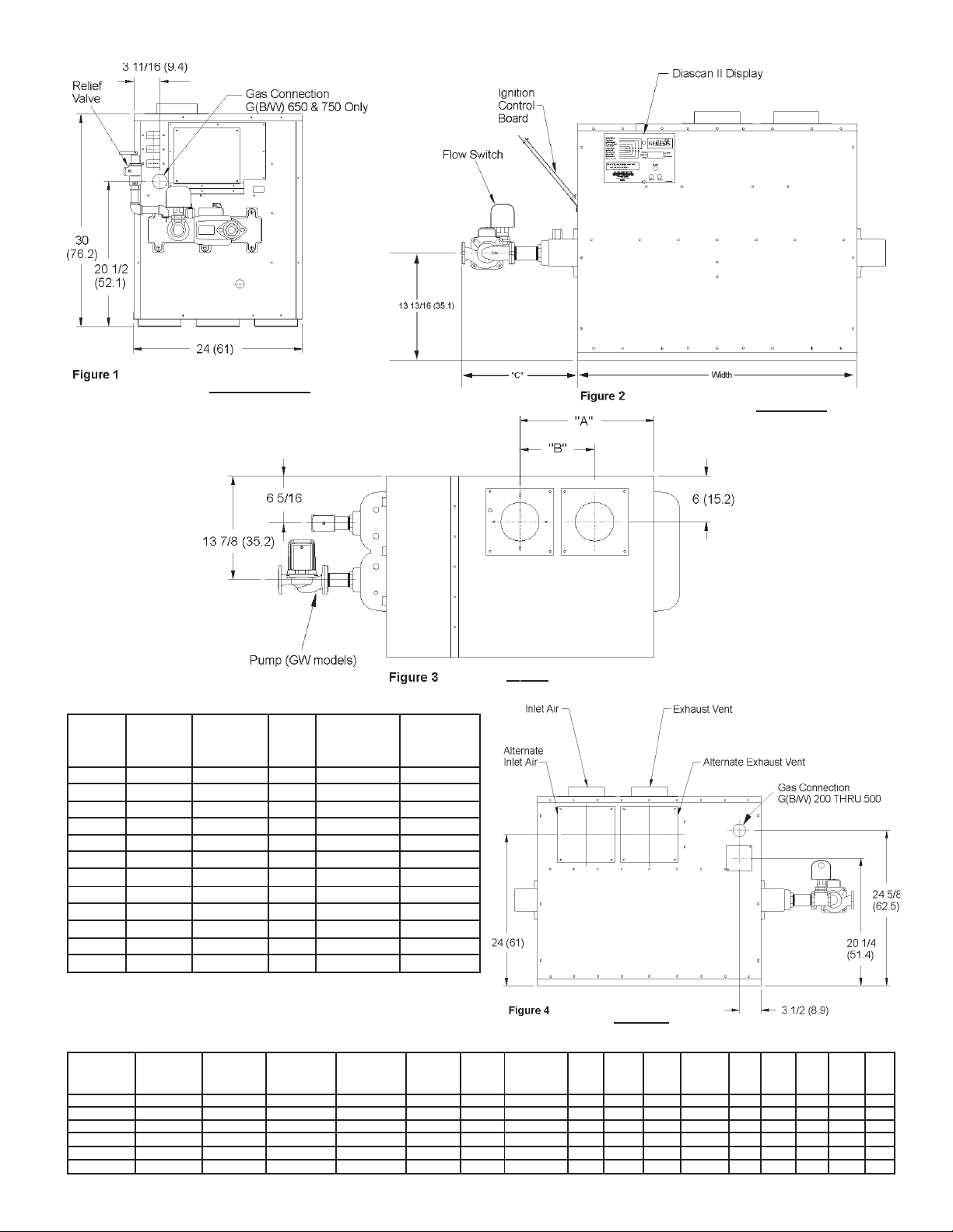
Table 1B: Rough-in Dimensions
Btu/hr.Input KW Input Exhaust Water Gas
Btu/hr. Input KW Input Propane (LP) Propane (LP) Vent Size Inlet Air Connecions Piping Width Width A A B B C C
Model Natural Gas Natural Gas Gas Gas (Inch) (Inch) Size (Inch) (Inch) (Inch) (mm) (inch) (mm) (Inch) (mm) (Inch) mm
GB/GW 200 199,900 59 199,900 59 4 4 1 1/2 3/4 23 1/4 591 11 11/16 2 97 7 1/2 191 12 305
GB/GW 300 300,000 88 300,000 88 5 5 1 1/2 3/4 29 1/2 749 14 13/16 376 9 229 12 305
GB/GW 400 399,900 117 399,900 117 6 6 1 1/2 1 35 3/4 908 17 15/16 456 9 229 14 3/4 375
GB/GW 500 500,000 14 7 500,000 147 6 6 2 1 42 1067 21 1/16 535 9 229 14 3/4 3 75
GB/GW 650 650,000 19 0 650,000 190 8 8 2 1 1/4 51 3/8 1305 25 3/4 654 9 229 14 3/4 375
GB/GW 750 750,000 22 0 750,000 220 8 8 2 1 1/4 57 5/8 1464 28 7/8 733 9 229 17 1/4 438
REAR
3
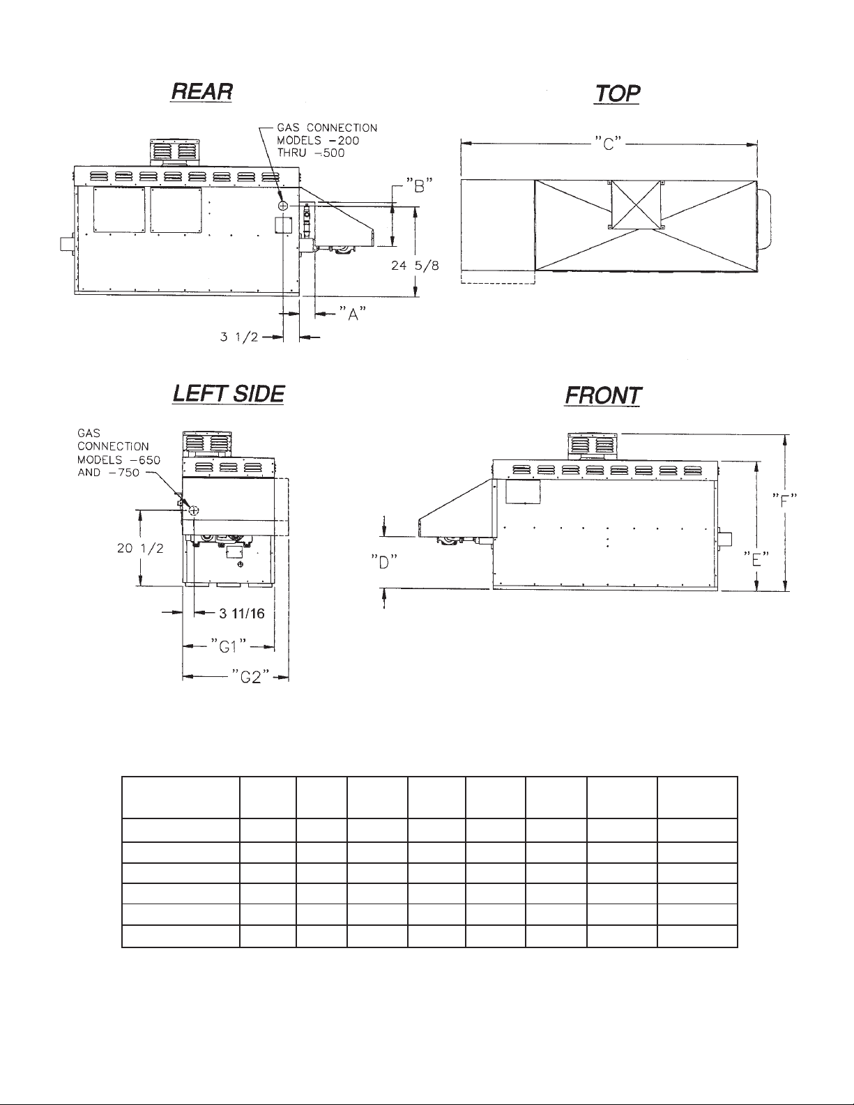
Table 1C: Outdoor Unit DImensions
MODEL
NUMBER "A" "B" "C" "D" "E" "F" "G1" "G2"
GBO/GWO-200 3 9 3/4 42 3/4 13 5/8 34 5/8 41 7/8 24 3/16 —
GBO/GWO-300 3 9 3/4 49 13 5/8 34 5/8 41 7/8 24 3/16 —
GBO/GWO-400 3 9 3/4 55 1/4 13 5/8 34 5/8 41 7/8 24 3/16 —
GBO/GWO-500 3 9 3/4 61 1/2 13 5/8 34 5/8 41 7/8 24 3/16 —
GBO/GWO-650 3 9 3/4 70 7/8 13 5/8 34 5/8 41 7/8 — 27 11/16
GBO/GWO-750 3 9 3/4 77 1/8 13 5/8 34 5/8 41 7/8 — 27 11/16
4
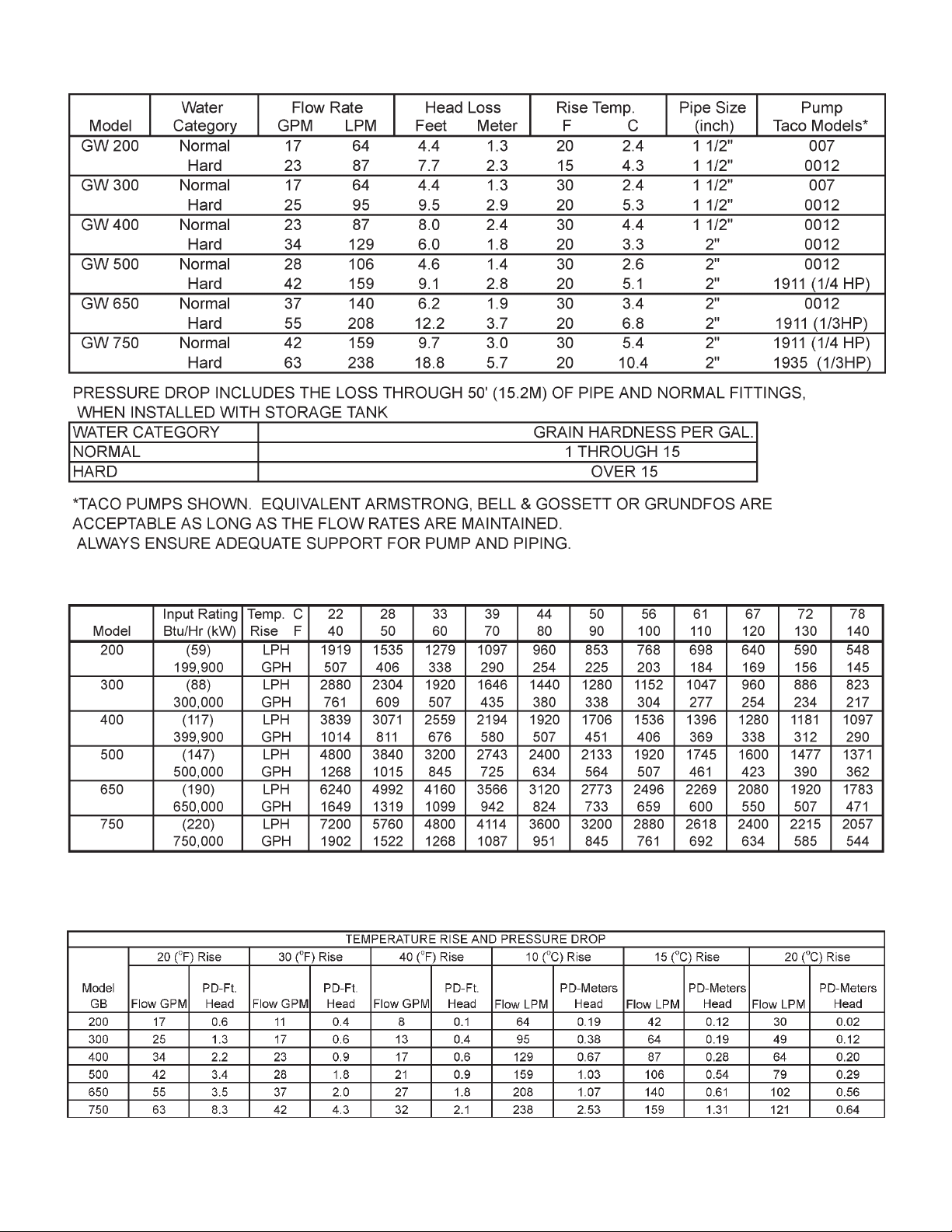
Table 2: Pump Performance
Table 3: Recovery Capacities
Table 4: Heat Exchanger Pressure Drop
5
FOREWORD
CAUTION
TEXT PRINTED OR OUTLINED IN RED CONTAINS INFORMATION RELATIVE TO YOUR SAFETY. PLEASE READ
COMPLETELY BEFORE USING APPLIANCE.
Detailed installation diagrams are in this manual. These diagrams
will provide the installer with a reference of materials needed and
a suggested method of piping. IT IS NECESSARY THAT ALL
WATER AND GAS PIPING, AND THE ELECTRICAL WIRING
BE INSTALLED AND CONNECTED AS SHOWN IN THE
DIAGRAMS.
CHECK THE DIAGRAMS THOROUGHLY BEFORE STARTING
INSTALLATION TO AVOID POSSIBLE ERRORS AND TO
MINIMIZE TIME AND MATERIALS COST. SEE FIGURES 1
THROUGH 4 AND TABLES 1A, 1B AND 1C.
This design complies with the latest edition of the
Z21.13, for Gas-Fired Low-Pressure Steam and Hot Water Boilers,
CGA 4.9/CGA 3.3 latest edition as a low-pressure boiler.
or
MAKE SURE THE GAS ON WHICH THE BOILER WILL
OPERA TE IS THE SAME AS THA T SPECIFIED ON THE BOILER
RATING PLATE.
The boiler installation must conform to these instructions and the
requirements of the local authority having jurisdiction.
ANSI Standard
CAUTION
Label all wires prior to disconnection when servicing controls.
Wiring errors can cause improper and dangerous operation of
the boiler.
"Verify proper operation after servicing."
INSTALLATION CLEARANCES
Sufficient area should be provided at the front (2 feet minimum) and at the water connection side (1 foot minimum) of
the unit for proper servicing. Sufficient clearance should be
provided at the return header side of the boiler to permit access
to heat exchanger tubes for cleaning. In a utility room installation, the door shall be wide enough to allow the boiler to enter or
to permit the replacement of another appliance.
These boilers are approved for installation on noncombustible
flooring in an alcove with minimum clearance to combustibles of:
3 inches Sides, and Back; 3 inches top, Front Alcove, 6 inches
Vent.
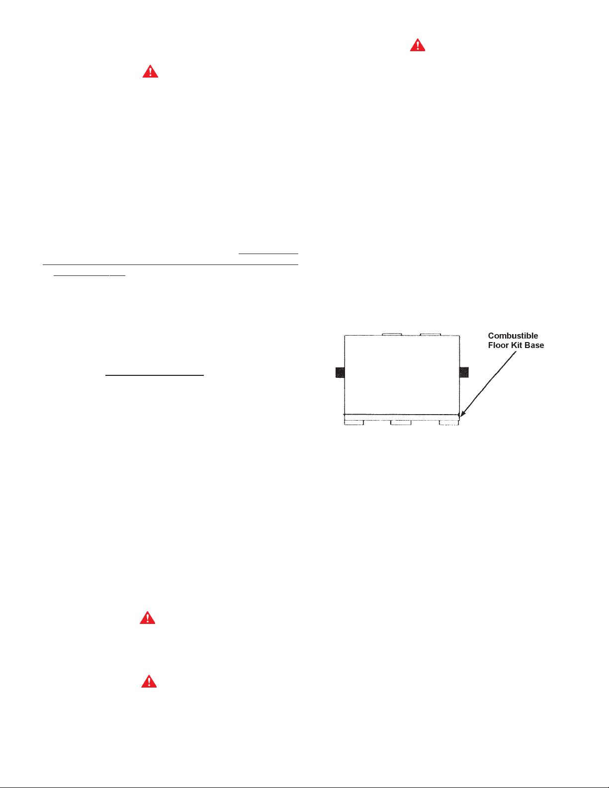
For installation on combustible flooring use the Combustible Floor
Kit. The combustible floor kit base adds 4" to the overall height
of the boiler. See figure 5.
In the absence of local code requirements, the installation must
conform to the
CGA-B149.1 or B149.2 (most recent edition).
These manuals can be purchased from the American Gas
Association Laboratories, 8501 East Pleasant Valley Road,
Cleveland, OH 44131 or Canadian Gas Association Laboratories,
55 Scarsdale Road, Don Mills, Ontario Canada M3B 2R3.
Replacement parts may be ordered through A. O. Smith dealers,
authorized servicers or distributors. Refer to the Yellow Pages
for where to call or contact (in United States) the A. O. Smith
Water Products Company, 5621 West 115th Street, Alsip, IL
60803, 1-800-433-2545 or (in Canada) A. O. Smith Enterprises
Ltd., 768 Erie Street, Stratford, Ontario, Canada N5A 6T3,
519-271-5800. When ordering parts be sure to state the quantity,
part number and description of the item including the complete
model and serial number as it appears on the product. Refer to
the parts lists for more information.
For Technical Assistance call A. O. Smith Technical
Information Center at 1-800-527-1953.
National Fuel Gas Code, ANSI Z223.1 or CAN/
REPLACEMENT PARTS
WARNING
THE WA TER MANIFOLD IS NOT DESIGNED TO SUPPOR T THE
WEIGHT OF THE WATER PIPING SYSTEM. AS ON ALL
BOILER INSTALLATIONS, SPECIAL CARE MUST BE TAKEN
TO ENSURE PROPER SUPPORT.
WARNING
UNDER NO CIRCUMSTANCES SHOULD THE EQUIPMENT
ROOM WHERE THE BOILER IS INST ALLED EVER BE UNDER
NEGA TIVE PRESSURE. PAR TICULAR CARE MUST BE T AKEN
WHEN EXHAUST FANS, COMPRESSORS, AIR HANDLING
EQUIPMENT, ETC., MAY INTERFERE WITH THE COMBUSTION AND VENTILATION AIR SUPPLIES OF THIS BOILER.
Figure 5: Boiler on Combustible Floor Base
Model Combustible Floor Kit
(GB/GW)-200 210202-000
(GB/GW)-300 210202-001
(GB/GW)-400 210202-002
(GB/GW)-500 210202-003
(GB/GW)-650 210202-004
(GB/GW)-750 210202-005
Two inch clearance is allowable from combustible construction
to hot water pipes.
LEVELLING
Each unit must be checked after installation to be certain that it
is level.
CONDENSATION WARNING
Your boiler is not designed to operate with a boiler inlet water
temperature of less than 120
temperatures will result in significant condensation developing
on the heat exchanger. This situation can cause a corrosive
environment for the heat exchanger, burners and venting resulting
in premature damage, which could result in serious personal injury
or death. Damage caused by excessive condensation will not be
covered under the limited warranty.
For systems that use large volumes of cold water or systems
utilizing heavy water draws, condensation can be prevented by
using a bypass loop. See page 27.
6
o
F (38oC). Colder inlet water

FEATURES
IMPORTANT
Only qualified personnel shall perform the initial firing of the heater .
At this time the user should not hesitate to ask the start-up
technician any questions regarding the operation and maintenance
of the unit.
Lighting and Operating instructions are included with this manual.
By using these instructions, the user may be able to make minor
operational adjustments and save unnecessary service calls.
However, the user should not attempt repairs, but should contact
a service technician or gas supplier.
The T & P relief valve should have a temperature rating of 210°F ,
a pressure rating NOT exceeding the lowest rated working pressure of any system component, and a discharge capacity exceeding the total input of the water boilers supplying water to the
storage tank.
Locate the T & P relief valve (a) in the top of the tank, or (b) in the
side of the tank on a center line within the upper six (6) inches of
the top of the tank. See figs. 20 and 22. The tapping shall be
threaded in accordance with the latest edition of the Standard for
Pipe Threads, General Purpose (inch), ANSI/ASME B1.20.1. The
location of, or intended location for, the T & P relief valve shall be
readily accessible for servicing or replacement.
SAFETY RELIEF VALVES
Your local code authority may have other specific relief valve
requirements not covered below.
WARNING
THE PURPOSE OF A SAFETY RELIEF VALVE IS TO AVOID
EXCESSIVE PRESSURE WHICH MAY CAUSE TANK
EXPLOSION, SYSTEM OR BOILER DAMAGE.
TO AVOID WATER DAMAGE A DRAIN LINE MUST BE
CONNECTED TO A SAFETY RELIEF VALVE TO DIRECT
DISCHARGE TO A SAFE LOCATION. A DRAIN LINE MUST
NOT BE REDUCED FROM THE SIZE OF THE VALVE OUTLET
AND IT MUST NOT CONTAIN ANY VALVES BETWEEN THE
BOILER AND THE RELIEF VALVE OR THE RELIEF VALVE AND
THE DRAIN EXIT. IN ADDITION, THERE SHOULD NOT BE
ANY RESTRICTIONS IN A DRAIN LINE NOR SHOULD IT BE
ROUTED THROUGH AREAS WHERE FREEZING CONDITIONS
MIGHT OCCUR. DO NOT THREAD OR CAP THE DRAIN LINE
EXIT. RESTRICTING OR BLOCKING A DRAIN LINE WILL
DEFEAT THE PURPOSE OF THE RELIEF VALVE AND MAY
CREATE AN UNSAFE CONDITION. INSTALL A DRAIN LINE
WITH A DOWNWARD SLOPE SUCH THAT IT NATURALLY
DRAINS ITSELF.
If any safety relief valve is replaced, the replacement valve must
comply with the latest version of the ASME Boiler and Pressure
Vessel Code, Section IV (HEATING BOILERS). Select a relief
valve with a discharge rating NOT less than the boiler input, and
a set pressure NOT exceeding the working pressure of any
component in the system.
The storage tank temperature and pressure relief valve must
comply with the applicable construction provisions of the Standard
for Relief Valves and Automatic Gas Shut-off Devices for Hot
Water Supply Systems, ANSI Z21 or CAN/CGA-B149.1 or B149.2
(latest edition). The valve must be of the automatic reset type
and not embody a single-use type fusible plug, cartridge or linkage.
FOR HOT WATER HEATING SYSTEMS, the boilers are shipped
with a 50 psi pressure relief valve. This relief valve is factory
installed in the water outlet header of the boiler, see figure 1.
FOR HOT WATER SUPPLY SYSTEMS, the boilers are shipped
with a 125 psi pressure relief valve. This relief valve is factory
installed in the water outlet header of the boiler, see figure 1.
This ASME-rated valve has a discharge capacity that exceeds
the maximum boiler input rating and a pressure rating that does
not exceed the maximum working pressure shown on the boiler
rating plate.
In addition, an A.G.A. design-certified and ASME-rated temperature and pressure (T & P) relief valve must be installed on each
and every water storage tank in the hot water supply system.
INST ALLA TION INSTRUCTIONS
REQUIRED ABILITY
INSTALLATION OR SERVICE OF THIS BOILER REQUIRES
ABILITY EQUIV ALENT T O THA T OF A LICENSED TRADESMAN
IN THE FIELD INVOL VED. PLUMBING, AIR SUPPL Y, VENTING,
GAS SUPPLY AND ELECTRICAL WORK ARE REQUIRED.
LOCATION
When installing the boiler, consideration must be given to proper
location. Location selected should be as close to the stack or
chimney as practical with adequate air supply and as centralized
with the piping system as possible. This location should also be
such that the gas ignition system components are protected from
water (dripping, spraying, etc.) during appliance operation and
service [circulator replacement, control replacement, etc.].
• THE BOILER MUST NOT BE INSTALLED ON CARPETING.
• THE BOILER SHOULD NOT BE LOCATED IN AN AREA
WHERE IT WILL BE SUBJECT TO FREEZING.
• THE BOILER SHOULD BE LOCATED NEAR A FLOOR
DRAIN.
• THE BOILER SHOULD BE LOCATED IN AN AREA WHERE
LEAKAGE FROM THE BOILER OR CONNECTIONS WILL
NOT RESULT IN DAMAGE TO THE ADJACENT AREA OR
TO LOWER FLOORS OF THE STRUCTURE.
WHEN SUCH LOCATIONS CANNOT BE AVOIDED, A SUIT ABLE
DRAIN PAN SHOULD BE INSTALLED UNDER THE BOILER.
Such pans should be fabricated with sides at least 2-1/2" deep,
with length and width at least 2" greater than the dimensions of
the boiler plus piping connections and must be piped to an
adequate drain. The pan must not restrict combustion air flow.
WARNING
THERE IS A RISK IN USING FUEL BURNING APPLIANCES IN
ROOMS OR AREAS WHERE GASOLINE, OTHER FLAMMABLE
LIQUIDS OR ENGINE DRIVEN EQUIPMENT OR VEHICLES
ARE STORED, OPERATED OR REPAIRED. FLAMMABLE
V APORS ARE HEAVY AND TRAVEL ALONG THE FLOOR AND
MAY BE IGNITED BY THE IGNITER OR MAIN BURNER FLAMES
CAUSING FIRE OR EXPLOSION. SOME LOCAL CODES
PERMIT OPERA TION OF GAS APPLIANCES IF INSTALLED 18
INCHES OR MORE ABOVE THE FLOOR. THIS MAY REDUCE
THE RISK IF LOCATION IN SUCH AN AREA CANNOT BE
AVOIDED.
FLAMMABLE ITEMS, PRESSURIZED CONTAINERS OR A N Y
OTHER POTENTIAL FIRE HAZARDOUS ARTICLES MUST
NEVER BE PLACED ON OR ADJACENT TO THE BOILER.
OPEN CONTAINERS OF FLAMMABLE MATERIAL SHOULD
NOT BE STORED OR USED IN THE SAME ROOM WITH THE
BOILER.
7

If the boiler is installed above the level of heating system terminal
units, a low water cutoff device must be installed in the boiler
outlet at the time of installation.
CHEMICAL VAPOR CORROSION
Heat exchanger corrosion and component failure can be caused
by the heating and breakdown of airborne chemical vapors. Spray
can propellants, cleaning solvents, refrigerator and air conditioning
refrigerants, swimming pool chemicals, calcium and sodium
chloride, waxes, and process chemicals are typical compounds
which are corrosive. These materials are corrosive at very low
concentration levels with little or no odor to reveal their presence.
Products of this sort should not be stored near the boiler. Also,
air which is brought in contact with the water boiler should not
contain any of these chemicals. If necessary, uncontaminated
air should be obtained from remote or outside sources.
MANUAL RESET HIGH TEMPERATURE
SAFETY OPERATING CONTROL LIMIT
This device prevents the water temperature from reaching 250
o
This device is located in the outlet water portion of the header
casting.
AUTOMATIC RESET
HIGH TEMPERATURE LIMIT CONTROL
CAUTION
LIMIT CONTROLS ARE
NOT TO BE USED AS A THERMOST A T.
ALL MODELS - This limit is a safety device in series with the
ignition system. Set the limit control to a minimum of 40°F above
the maximum designed system temperature. If the boiler outlet
water temperature should exceed the high limit setting, the main
gas valves will close. The limit control is factory set at 180°F and
has an adjustable range from 110 to 240°F. The operating
differential is also adjustable from 5 to 50°F.
TANK PROBE
FOR HOT WATER SUPPLY SYSTEMS (GW models), A tank
probe is supplied with each hot water supply boiler. The inlet
water temperature will default to the tank temperature on the DiaScan II display when the tank probe is installed.
"Pigtails" of field-supplied wires should be spliced to "pigtails" of
tank probe and to "pigtails" at the junction box. See figure 21 for
the tank probe installation. Follow the instructions on page 22
for the operation and temperature setting procedures for the
temperature sensor.
FOR HOT WATER HEATING SYSTEMS (GB models) Due to
the many various types of systems and operating conditions, no
factory operating control is supplied with the GB models. GB
models require a field supplied operating control be installed in
the system. Such as: loop stat, indoor/outdoor reset control,
sequencing panel, or energy management system. These types
of controls connect to the brown thermostat wires in the junction
box on the boiler. Do not operate this boiler using the internal
high limits only , you must use an operating stat as mentioned
above.
CIRCULATING PUMP
The pump flow rate should not exceed the maximum recommended flow rate, see table 2.
FOR HOT WATER SUPPL Y SYSTEMS (GW models), the circulating pump is an integral part of the Boiler, see figure 3. This
pump has been lubricated at the factory, and future lubrication
should be in accordance with the motor manufacturer's instructions provided as supplement to this manual.
FOR HOT WATER HEATING SYSTEMS (GB models), the circulating pump is NOT provided and must be field-installed.
SAFETY FLOW SWITCH (Supplied)
The safety flow switch is a safety device which is installed at the
water outlet of the unit to prevent main burner operation in the
event of inadequate water flow through the boiler.
This switch is wired into the Ignition Control, and its function is
displayed on the Ignition Control Display. Green light on - switch
is closed, and red light on - inadequate water flow or flow switch
failure.
LOW WATER CUTOFF (Not Supplied)
If low water protection is required by the authorities having jurisdiction, a low water cutoff switch should be installed next to the
boiler in the outlet water line as shown in figure 23. The switch
should receive periodic (every six months) inspection to assure
proper operation. A low water cutoff device of the float type should
be flushed every six months.
F.
DRAIN VALVE
(Not Supplied)
Drain valves must be obtained and installed on each boiler and
tank for draining purposes.
AIR REQUIREMENTS
FOR SAFE OPERATION, AN AMPLE SUPPLY OF AIR MUST
BE PROVIDED FOR PROPER COMBUSTION AND
VENTILATION IN ACCORDANCE WITH THE NATIONAL FUEL
GAS CODE, ANSI Z223.1 OR CAN/CGA-B149.1 OR B149.2
(LATEST EDITIONS) OR APPLICABLE PROVISIONS OF THE
LOCAL BUILDING CODES. AN INSUFFICIENT SUPPLY OF
AIR MAY RESUL T IN A YELLOW , LUMINOUS BURNER FLAME,
CARBONING OR SOOTING OF THE FINNED HEAT
EXCHANGER, OR CREATE A RISK OF ASPHYXIATION. DO
NOT OBSTRUCT THE FLOW OF COMBUSTION AND
VENTILATION AIR.
UNCONFINED SPACE
In buildings of conventional frame, brick or stone construction,
unconfined spaces may provide adequate air for combustion.
If the unconfined space is within a building of tight construction
(buildings using the following construction: weather stripping,
heavy insulation, caulking, vapor barrier, etc.), air for combustion,
ventilation, must be obtained from outdoors or spaces freely
communicating with the outdoors. The installation instructions
for confined spaces in tightly constructed buildings must be
followed to ensure adequate air supply.
(a) U. S. INSTALLATIONS
When drawing combustion and dilution air from inside a
conventionally constructed building to a confined space, such a
space shall be provided with two permanent openings, ONE
WITHIN 12 INCHES OF THE ENCLOSURE TOP AND ONE
WITHIN 12 INCHES OF THE ENCLOSURE BOTTOM. Each
opening shall have a free area of at least one square inch per
1000 Btuh of the total input of all appliances in the enclosure, but
not less than 100 square inches.
If the confined space is within a building of tight construction, air
for combustion, ventilation, and draft hood dilution must be
obtained from outdoors. When directly communicating with the
outdoors or communicating with the outdoors through vertical
ducts, two permanent openings, located in the above manner,
8
WARNING
CONFINED SPACE
shall be provided. Each opening shall have a free area of not
less than one square inch per 4000 Btuh of the total input of all
appliances in the enclosure. If horizontal ducts are used, each
opening shall have a free area of not less than one square inch
per 2000 Btuh of the total input of all appliances in the enclosure.
(b) CANADIAN INSTALLATIONS
Ventilation of the sp ace occupied by the boiler(s) shall be provided
by an opening for ventilation air at the highest practical point
communicating with outdoors. The total cross-sectional area
shall be at least 10% of the area of the combustion air opening
but in no case shall the cross-sectional area be less than 10
square inches (6500 mm
2
).
In addition to the above, there shall be permanent air supply
opening(s) having a cross-sectional area of not less than 1 square
inch per 7,000 BTUH (310 mm
plus 1 square inch per 14,000 BTU in excess of 1,000,000
BTUH
2
/KW) up to and including 1,000,000
BTUH. This opening(s) shall be located at, or ducted to, a point
neither more than 18" (450 mm) nor less than 6 inches (150 mm)
above the floor level.
Where power vented equipment is used in the same room as the
boiler, sufficient air openings must be supplied.
UNDERSIZED OPENINGS MA Y RESUL T IN INSUFFICIENT AIR
FOR COMBUSTION.
Where an exhaust fan is installed in the same room with a boiler,
sufficient openings for air must be provided in the walls.
UNDERSIZED OPENINGS WILL CAUSE AIR TO BE DRAWN
INTO THE ROOM THROUGH THE CHIMNEY, CAUSING POOR
COMBUSTION. SOOTING MA Y RESUL T WITH AN INCREASED
RISK OF ASPHYXIATION.
!
VENTING THE BOILER
This boiler is approved to be vented as a Category I, Category III
(horizontal venting), or a Direct Vent appliance. The Horizontal
and Direct Venting options require a special vent kit.
WARNING
THE INSTRUCTIONS IN THIS SECTION ON VENTING THE
BOILER MUST BE FOLLOWED TO AVOID CHOKED
COMBUSTION OR RECIRCULA TION OF FLUE GASES. SUCH
CONDITIONS CAUSE SOOTING OR RISKS OF FIRE AND
ASPHYXIATION.
STANDARD (VERTICAL) VENTING, CATEGORY I
THIS BOILER MAY BE VENTED ACCORDING TO TABLE 5A
AND 5C (ALSO SEE FIGURE 6). AT LEAST TYPE B VENTING
MUST BE USED WITH THE STANDARD VENTING OPTION
(thru-the-roof) USING THE NATIONAL FUEL GAS CODE VENT
TABLES.* TYPE B VENT PIPE
BOILER IS VENTED HORIZONTALLY OR AS A DIRECT VENT
(SEE PAGES 10 AND 11). ALL LOCAL UTILITY, STATE/
PROVINCIAL, REGULATIONS ON VENTING MUST BE
FOLLOWED.
VENT SIZING, INSTALLATION AND TERMINATION SHALL BE
IN ACCORDANCE WITH THE
ANSI Z223.1 OR CAN/CGA-B149.1 OR B149.2 (LATEST
EDITIONS).
VENT CONNECTION
Model Number Vent Connector
G(W,B) 200 4"
G(W,B) 300 5"
G(W,B) 400 6"
G(W,B) 500 6"
G(W,B) 650 8"
G(W,B) 750 8"
* For vent arrangements other than T able 5A and for proper boiler
operation, a barometric damper is required to maintain draft
between -0.02" w.c. and -0.04" w.c at 2 feet above the boiler
vent collar.
CANNOT BE USED IF THE
NATIONAL FUEL GAS CODE,
Horizontal or Horizontal Direct Vent
Special Vent Kit Model Number
210320-000 G(W,B) 200
210320-001 G(W,B) 300
210320-002 G(W,B) 400
210320-002 G(W,B) 500
210320-003 G(W,B) 650
210320-003 G(W,B) 750
Vertical Direct Vent Special Vent Kit Model Number
210317-000 G(W,B) 200
210317-001 G(W,B) 300
210317-002 G(W,B) 400
210317-002 G(W,B) 500
210317-003 G(W,B) 650
210317-003 G(W,B) 750
CAUTION
When venting the Genesis Boiler through oversize chimney
(including masonry chimneys), additional care must be
exercised to assure proper draft. For proper operation, a
minimum draft of -0.02" w.c. and a maximum draft of -0.04"
w.c. must be maintained. In instances of excessive draft, a
barometric damper may be required to assist in maintaining the
proper draft. Draft should be measured 2 feet above the boiler
vent collar.
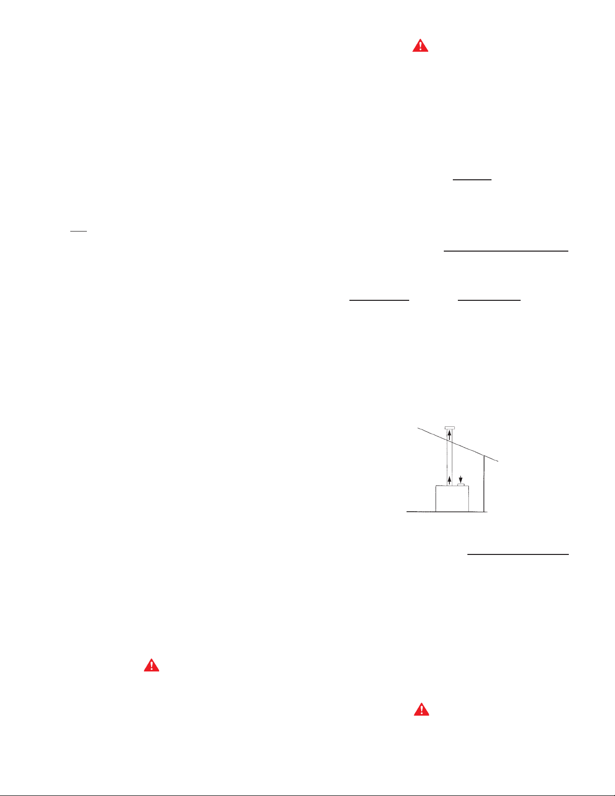
Figure 6. Single Pipe Vertical Termination
Vent connections must be made to an adequate stack or chimney
and shall be in accordance with the National Fuel Gas Code,
ANSI Z223.1 or CAN/CGA-B149.1 or B149.2 or applicable
provisions of the local building codes. Size and install proper
size vent pipe.
Horizontal runs of vent pipe shall be securely supported by
adequately placed (approximately every 4 feet), noncombustible
hangers suitable for the weight and design of the materials
employed to prevent sagging and to maintain a minimum upward
slope of 1/4" per foot from the boiler to the vent terminals.
Dampers or other obstructions must not be installed in the vent.
Be sure that the vent connector does not extend beyond the inside
wall of the chimney.
CONNECTING BOILER TO A COMMON VENT
CAUTION
When the GENESIS boilers are commonly vented, additional care
must be exercised to assure proper draft. For proper operation,
a minimum draft of -0.02" w.c. and a maximum draft of -0.04"
w.c. must be maintained AT EACH INDIVIDUAL BOILER. In
9
instances of excessive draft, a barometric damper may be required
to assist in maintaining the proper draft. Draft should be measured
2 feet above EACH boiler vent collar.
Do not connect the boiler to a common vent or chimney with
solid fuel burning equipment. This practice is prohibited by most
local building codes as is the practice of venting gas fired
equipment to the duct work of ventilation systems.
Where a separate vent connection is not available and the vent
pipe from the boiler must be connected to a common vent with
an oil burning furnace, the vent pipe should enter the common
vent or chimney at a point ABOVE the flue pipe from the oil furnace.
UL/ULC listed double wall type B-1 gas vents, through 8" diameter,
can be installed in heated and unheated areas and can pass
through floors, ceilings, partitions, walls and roofs, provided the
required clearance is observed.
At the time of removal of an existing boiler, the following steps
shall be followed with each appliance remaining connected to
the common venting system. Perform these steps while the other
appliances remaining connected to the common venting system
are not in operation.
Seal any unused openings in the common venting system.
Visually inspect the venting system for proper size and horizontal
pitch and determine there is not blockage or restriction, leakage,
corrosion and other deficiencies which could cause an unsafe
condition.
All boiler venting systems shall be installed in accordance with
National Fuel Gas Code, ANSI Z223.1 or CAN/CGA-B149.1
the
or B149.2 (latest version), or applicable provisions of the local
building codes.
SINGLE PIPE HORIZONTAL VENTING
Vent sizing, installation and termination shall be in accordance
with the
NATIONAL FUEL GAS CODE, ANSI Z223.1 OR CAN/
CGA-B149.1 OR B149.2 (LATEST EDITIONS). If applicable, all
local, utility, state/provincial regulations on venting must be
followed. This boiler may be vented according to table 5A and
5C (also, see figure 7). The exhaust vent pipe must be "Saf-TVent" manufactured by Heat-Fab Inc. The exhaust vent material
type is AL 29-4C. This vent system must be 100% sealed with a
condensate trap located as close to the boiler as possible.
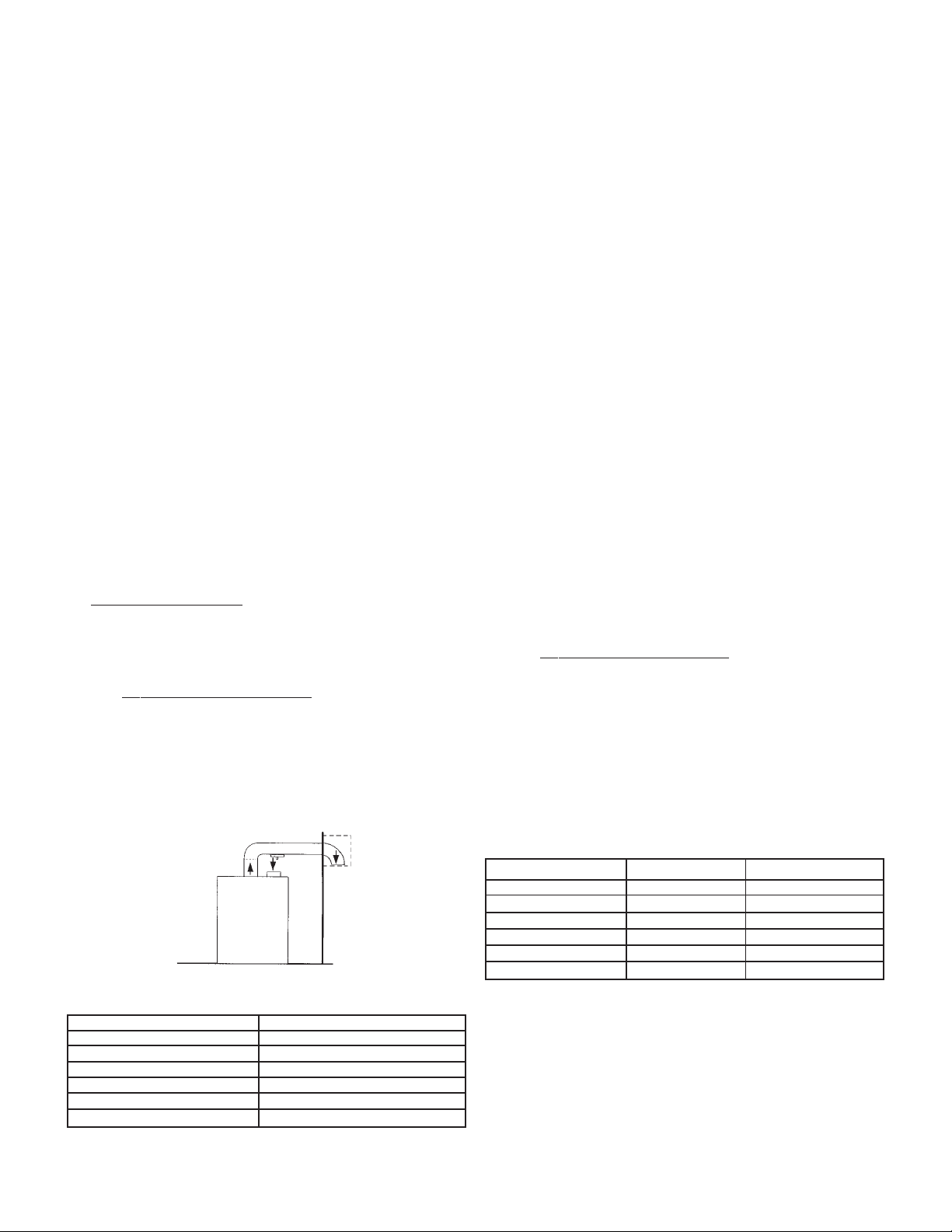
Figure 7. Single Pipe Horizontal Termination
T ABLE 5A –SINGLE PIPE HORIZONT AL AND VERTICAL VENTING
MODEL EXHAUST VENT*
GB/GW-200 110'
GB/GW-300 110'
GB/GW-400 50'
GB/GW-500 50'
GB/GW-650 50'
GB/GW-750 50'
* When sizing exhaust piping and intake air piping, 90-degree elbows are
equivalent to 10 feet of straight pipe and 45-degree elbows are equal to 5
feet of straight pipe.
Intake/Exhaust Installation Requirements (See figures 6, 7
and 14):
1. The termination must be a minimum of 12 inches above
anticipated snow or grade level whichever is higher.
2. Due to normal formation of water vapor in the combustion
process, horizontal terminations must not be located over
areas of pedestrian or vehicular traffic, (e.g., public walkways
or over areas where condensate could create a nuisance or
hazard. This is especially true in colder climates where ice
buildup is likely to occur. A.O. Smith Corporation will not be
held liable for any personal injury or property damage due to
any dislodging of ice.
3. The minimum distance from the exhaust terminal to any
window, gravity air inlet to a building, or from gas or electric
meter(s) is 6 feet horizontally, 4 feet below and 2 feet above.
4. The minimum distance from the exhaust terminal to an inside
corner formed by two exterior walls is 6 feet but 10 feet is
recommended where possible.
5. Maintain a minimum distance of 4 feet from any soffit or eave vent
to the exhaust terminal.
6. Maintain a minimum distance of 10 feet from any forced air
inlet to a building. Any fresh air or make up air inlet such as
a dryer or furnace area is considered to be a forced air inlet.
7. Avoid areas where condensate drainage may cause problems
such as above planters, patios, or adjacent to windows where
the steam from the flue gases may cause fogging.
8. Select the point of wall penetration where the minimum 1/4"
per foot of slope up can be maintained.
9. The through the wall termination kit is suitable for zero
clearance to combustible materials.
10.The mid point of the exhaust and intake air termination elbows
must be a minimum of 12 inches from the exterior wall.
DIRECT VENT HORIZONTAL AND VERTICAL VENTING
Vent sizing, installation and termination shall be in accordance
with the NATIONAL FUEL GAS CODE, ANSI Z223.1 OR CAN/
CGA-B149.1 OR B149.2 (LATEST EDITIONS). If applicable, all
local, utility, state/provincial regulations on venting must be
followed. This boiler may be vented according to table 5B and
5C (also, see figures 8, 9, 10 and 11). The exhaust vent pipe
must be "Saf-T-V ent" manufactured by Heat-Fab Inc. The exhaust
vent material type is AL 29-4C. This vent system must be 100%
sealed with a condensate trap located as close to the boiler as
possible.
The intake air piping can be PVC, CPVC, ABS or any suitable
intake air piping that can be sealed.
T ABLE 5B -DIRECT VENT HORIZONT AL AND VERTICAL VENTING
MODEL INTAKE* EXHAUST*
GB/GW-200 60' 60'
GB/GW-300 60' 60'
GB/GW-400 35' 35'
GB/GW-500 35' 35'
GB/GW-650 35' 35'
GB/GW-750 35' 35'
* When sizing exhaust piping and intake air piping, 90-degree elbows
are equivalent to 10 feet of straight pipe and 45-degree elbows are
equal to 5 feet of straight pipe.
Intake/Exhaust Installation Requirements (See Figures 8, 9,
10, 11 & 14):
1. The exhaust and intake air termination must be a minimum of
12 inches above anticipated snow or grade level which ever is
higher, see figure 14.
2. Due to normal formation of water vapor in the combustion
process, horizontal terminations must not be located over
areas of pedestrian or vehicular traffic, (e.g. public walkways
10
 Loading...