

Page 1
CIRCULATING LOOP HEAT EXCHANGER
PROMAX® XL
MODELS
• Installation
• Operation
MANUAL
• Maintenance
Fill in the Rating Pate Information Here:
MODEL NO.________________________________________
SERIAL NO.________________________________________
INSTALLATION DATE________________________________
Month Day Year
Fill in the Installation Information Here:
INSTALLER________________________________________
STREET ADDRESS__________________________________
CITY/STATE/ZIP_____________________________________
PHONE #__________________________________________
CAUTION
PLEASE READ THOROUGHLY BEFORE INSTALLING AND
USING THIS APPLIANCE.
DISTRIBUTOR________________________________________
STREET ADDRESS__________________________________
CITY/STATE/ZIP_____________________________________
PHONE #__________________________________________
SAVE THIS MANUAL FOR FUTURE REFERENCE.
PRINTED IN THE U.S.A. 0804 PART NO. 184911-000
www.aosmithwaterheaters.com
1
Page 2
GENERAL INFORMATION
This manual contains instructions for the installation, operation
and maintenance of the Promax
carefully before installing or using and keep it for future reference.
®
XL Heat Exchanger. Read it
Intended Applications
The XL Series of heat exchangers provide the means to obtain
an isolated source of hot water for radiant floor or wall heating,
hydronic air handling units and other closed loop applications.
The product line includes single wall and atmospherically vented
double wall heat exchangers with two separate btuh inputs for
each. The XL Series is intended for connection with the
A.O. Smith Promax® SL line of gas-fired water heaters. This unit
is not to be connected to pool or spa systems having highly
chlorinated water.
Rating Plate
A rating plate identifying the heat exchanger will be found on
the front of the unit. When referring to the heat exchanger, always
have the information listed on the rating plate readily available.
Customer Responsibilities
Please take the time to read not only this manual but also the
warranty sheet enclosed. Warranty of the Promax XL heat
exchanger and its parts will depend on proper installation,
maintenance and operation. Furthermore, the warranty shall be
void if the design or structure of the heat exchanger is, or is
attempted to be, modified or altered in any way, including, but
not limited to, by attaching non-Company approved appliances
or equipment. The manufacturer of this heat exchanger will not
be liable for any damages because of failure to comply with the
installation and operating instructions outlined on the following
pages. Use them as a guide to check the propriety of the heat
exchanger installation. You will need to maintain the heat
exchanger and water heater as outlined in their respective
manuals. Equipment in this carton was inspected and verified
to be in good condition at the time it left the factory. When
received, a visual inspection of the equipment should be made
and any damage noted on the delivery receipt. A damage claim
should be filed immediately with the carrier.
ALL TECHNICAL AND WARRANTY QUESTIONS SHOULD BE
DIRECTED TO THE LOCAL DEALER FROM WHOM THE HEAT
EXCHANGER WAS PURCHASED. IF YOU ARE UNSUCCESSFUL, PLEASE WRITE TO:
Repair Parts
For service or repair parts contact:
First: The Installing Contractor
Second: The local Distributor
AOSmith Water Products Company, Inc.
500 Lindahl Parkway
Ashland City, TN 37015
www.aosmithwaterheaters.com
TABLE OF CONTENTS
GENERAL INFORMATION .................................................. 2
TABLE OF CONTENTS ....................................................... 2
THEORY OF OPERATION .................................................. 2
SELECTING EQUIPMENT .................................................. 3
HEAT EXCHANGER PERFORMANCE ............................... 4
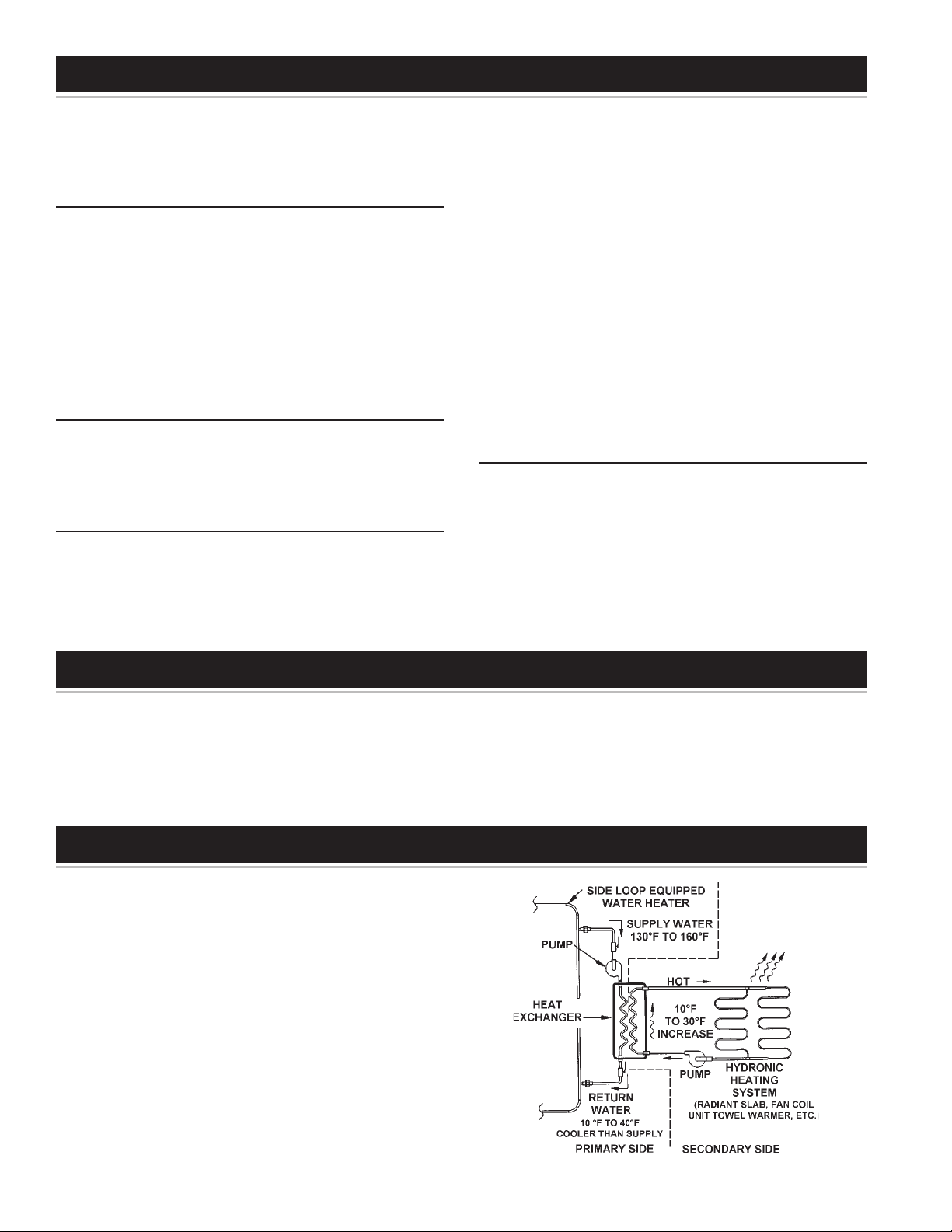
THEORY OF OPERATION
The pump on the XL unit draws water off of the top side loop
connection fitting (Supply Fitting), circulates it through the primary
side of the heat exchanger and back to the tank through the
return connection. While passing through the heat exchanger,
the water will lose from 10 to 40 degrees dependent on
application. A field supplied pump on the secondary side will
circulate water into the bottom fitting of the heat exchanger, out
the top and through a heating distribution system such as a
radiant slab or air handler. The rise in temperature for secondary
side fluid is very much dependant on application but should be
designed to provide 10 to 30° rise.
TYPICAL INSTALLATION ................................................. 5,6
WIRING ................................................................................ 6
MOUNTING THE HEAT EXCHANGER
TO WATER HEATER ........................................................ 6,7
REPLACEMENT PARTS ...................................................... 8
FIGURE 1
2
Page 3
SELECTING EQUIPMENT
The Promax XL heat exchanger systems are rated at “Nominal”
conditions. Their actual performance may vary significantly
based on application. System design should be undertaken only
by technically qualified individuals with an understanding
of pumps, recirculating water piping and heating applications.
These instructions do not cover load sizing or hydronic
heating requirements, but rather provide a means for selecting
the correct side loop water heater and heat exchanger to provide
a specific target heat output.
The RXLD Series is of vented double-wall construction for those
applications where design or local codes require double isolation
between fluid streams. Where applications may have a freeze
potential on the secondary side piping, propylene glycol may
be used to provide freeze protection.
NOTE: Ethylene glycol should not be used.
When selecting equipment for XL applications first compare the
target heating capacity to the listed output for the water heaters.
Prior to purchasing the water heater be sure to confirm water
heater specifications with current literature for the chosen product
PROMAX XL
SL MODELS OUTPUT APPLICATIONS
GCVH-40L 29,600 ALL XL MODELS
GCVT-40L 35,500 ALL XL MODELS
STANDARD GCVT-50L 38,000 ALL XL MODELS
VENT GCVX-50L 50,050 ALL XL MODELS
GCG-65L* 49,400 ALL XL MODELS
FCG-75L* 57,000 ALL XL MODELS
XGV-40L 30,400 ALL XL MODELS
XGV-50L 32,400 ALL XL MODELS
GCVH-40Q 29,600 ALL XL MODELS
DYNA- GCVT-40Q 35,500 ALL XL MODELS
CLEAN II GCVT-50Q 38,000 ALL XL MODELS
GCVX-50Q 50,100 ALL XL MODELS
GCG-65Q* 49,400 ALL XL MODELS
FCG-75Q* 60,100 ALL XL MODELS
DIRECT
VENT
POWER GPST-50L 39,900 ALL XL MODELS
VENT GPSX-50L 47,500 ALL XL MODELS
POWER GPDH-40L 30,400 RXLS 28 & 52 ONLY
DIRECT GPDT-50L 47,450 ALL XL MODELS
VENT GPDX-75L 53,200 ALL XL MODELS
GDVH-40L 30,000 RXLS 28 & 52 ONLY
GDVH-50L 36,000 ALL XL MODELS
GDVH-75L* 41,800 ALL XL MODELS
GPST-40L 38,000 ALL XL MODELS
GPST-75L 57,000 ALL XL MODELS
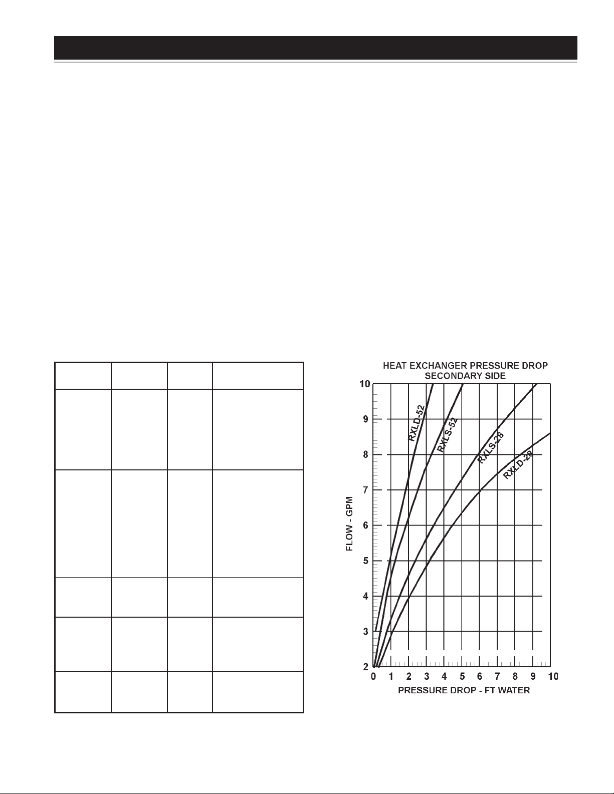
as specifications are subject to change. Next find the target
capacity on the horizontal axis of the heat exchanger
performance tables on page 4. Move vertically on the chart to
find the intersection of the capacity line and desired heat
exchanger outlet water temperature. This is the temperature of
the fluid going to the slab, coil, etc. From this intersection the
flow required for the secondary loop and the temperature drop,
also referred to as “Delta T” can be determined. The “Delta T”
shown is the drop in fluid temperature as it passes through the
target application. Once the secondary flow rate is determined,
the pressure drop for the heat exchanger can be read from the
chart , see Figure 2. This should be added to the pressure drop
for the rest of the system to determine pumping requirements.
The tables on page 4 show heat exchanger performance for a
range of temperature differentials of 10 to 30 degrees. Some
applications may not work well with high differentials.
NOTE: Not all heat exchangers will fit all models of
Promax SL water heaters. Refer to the Application Table to
insure compatibility.
FIGURE 2
3
Page 4

HEAT EXCHANGER PERFORMANCE
Heat exchanger temperature differentials (Delta T) are shown
for reference only. Actual values can be calculated by:
Delta T = Btuh/500/gpm
This will determine the difference between the heat exchanger’s
inlet and outlet water temperatures (Delta T).
4
Page 5

TYPICAL INSTALLATION
System piping is application dependent. The diagrams shown
reflect typical piping for the most simplistic installations. Slab
and tile floor heating often require limit controls to insure fluid
temperature limits are not exceeded. Refer to guidelines provided
by the Hydronic Applications supplier and/or the Radiant Panel
Association to avoid piping and control pitfalls. Always consult
local code bodies for code requirements specific to an application
or location.
Closed loop secondary side piping should always include a
pressure relief valve, expansion tank, drain valve and air
separation device. Installers should also provide isolation valves,
purge valves, stainers and temperature regulating devices
appropriate for the application.
The XL is provided with plugged, auxiliary connections on the
front side of the Heat Exchanger. These are common to the
primary side of the heat exchanger. These can be used as
installation points for thermowells, a drain, or as connection
points to flush the heat exchanger, see Figure 3.
The pump supplied with the Promax XL is powered by
Side Loop Water Heater with Closed Loop Distribution Only
FIGURE 3
FIGURE 4
5
Page 6

Side Loop Water Heater with Air Handler and Heat Exchanger
FIGURE 5
WIRING
115V/60 Hz and is equipped with a control relay located inside
the wiring termination box on the pump. This relay has a 24 volt
coil for low voltage control applications. For control applications
that power the pump directly, the relay can be bypassed and
removed. All wiring in the pump’s termination box should be
rated for 60°C or greater, and is to be done in accordance with
national and local electric codes.
MOUNTING THE HEAT EXCHANGER TO THE WATER HEATER
Attach Support Leg
Double Wall Models Only
Measure the distance from the return connection to the floor.
Set the heat exchanger face down and assemble the support
leg as shown. Adjust the length of the leg to the fitting height
plus 3”, see Figure 6.
FIGURE 6
6
Page 7

Mounting the Heat Exchanger
to All Models
NOTE: The units are very top heavy when attached only at the
return union. Make sure that the unit is well supported during fit
up. Mounting of the RXLD Models requires more than one
person.
Using thread seating compound install the included PEX lined
steel nipples into the side loop connections. Thread the return
fitting onto the lower PEX nipple and tighten the union nut firmly
by hand, see Figure 7. Set the heat exchanger on the return
fitting, see Figure 8. Then connect the supply fitting and rotate it
so that the pipe contacts the pump., see Figure 9. It may be
necessary to make a preliminary cut on the pipe to allow this.
Mark the pipe at the top of the pump and add 5/8” for solder
socket engagement, see Figure 9. Remove and cut the pipe at
the second mark. Reinstall the supply side assembly inserting
first into the pump and then connect it at the union, see
Figure 10. Make any adjustments needed to the length of the
support leg on units so equipped.
FIGURE 8
FIGURE 7
FIGURE 9
FIGURE 10
7
Page 8

REPLACEMENT PARTS
PROMAX
Item Description XL
1 ... Angle Fixed Support. ................................................................................................................................................ 184908-000
2 ... Angle Sliding Support ............................................................................................................................................... 184907-000
3 ... Back Cover,
Single wall (Models RXLS 28 & RXLS 52) ............................................................................................................... 184905-000
Double wall (Models RXLD 28 & RXLD 52) ............................................................................................................. 184909-000
4 ... Elbow, Cast Brass, 90°, 3/4C x 3/4FPT ................................................................................................................... 184921-000
5 ... Elbow, Copper, Preformed 3/4” ................................................................................................................................ 184902-000
6 ... Elbow, Copper, 3/4F x 3/4F ...................................................................................................................................... 0006600680
7 ... Front Cover,
Single Wall (Models RXLS 28 & RXLS 52) .............................................................................................................. 184906-000
Double Wall (Model RXLD28) .................................................................................................................................. 184910-000
Double-Wall (Model RXLD52) .................................................................................................................................. 184910-001
8 ... Heat Exchanger
Single Wall (Model RXLS 28) ................................................................................................................................... 184903-000
Single Wall (Model RXLS 52) ................................................................................................................................... 184903-001
Double Wall (Model RXLD 28) ................................................................................................................................. 184904-000
Double Wall ((Model RXLD 52) ................................................................................................................................ 184904-001
9 ... Nipple, Pex-Lined, .75” x 2.5” ................................................................................................................................... 194130-006
10 .. Pipe, Copper, Nominal Type L, 1.656 x 3/4” ............................................................................................................. - - - - - - - -
11 .. Pipe, Copper, Nominal Type L, 17” X 3/4” ................................................................................................................ - - - - - - - -
12 .. Pump, TACO, (006-B4-3) ......................................................................................................................................... 184915-000
13 .. Union, Di-Electric, 3/4FPT x 3/4C ............................................................................................................................ 0009400260
14 .. Valve, Ball, Full Port, 3/4” x 3/4” Sweat ................................................................................................................... 0007201260
8
 Loading...