

A. O. Smith BTP-540A Installation Manual
Instruction Manual
Low Lead Content
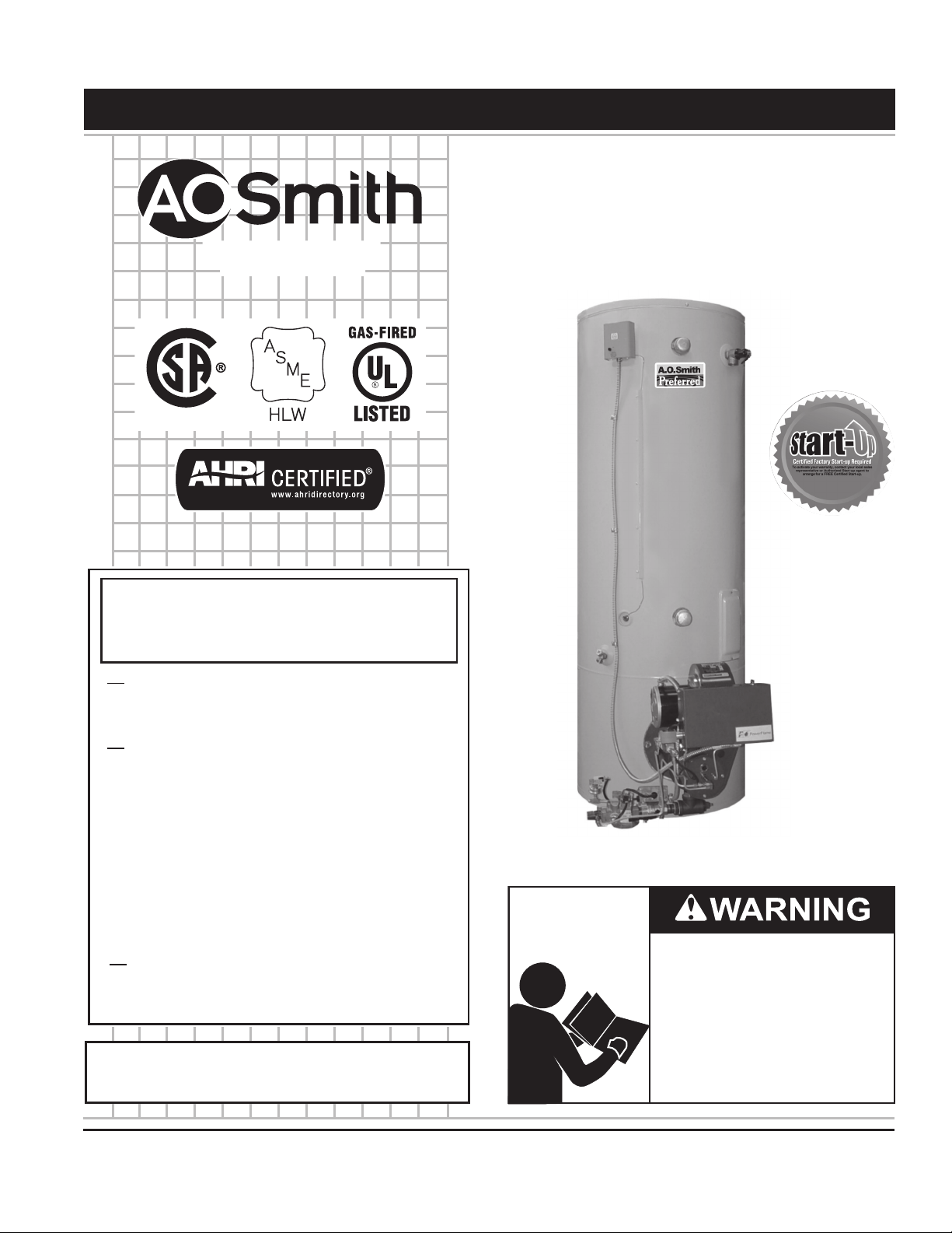
COMMERCIAL GAS WATER HEATERS
MODELS BTP(V)-540(A), 650(A), 740(A)
SERIES 104/105
INSTALLATION - OPERATION - SERVICE
500 Tennessee Waltz Parkway
Ashland City, TN 37015
- MAINTENANCE - LIMITED WARRANTY
WARNING: If the information in these
instructions is not followed exactly, a fire
or explosion may result causing property
damage, personal injury or death.
Do not store or use gasoline or other
flammable vapors and liquids in the
vicinity of this or any other appliance.
WHAT TO DO IF YOU SMELL GAS:
Do not try to light any appliance.
•
Do not touch any electrical switch; do
•
not use any phone in your building.
Immediately call your gas supplier
•
from a neighbor’s phone. Follow the
gas supplier’s instructions.
If you cannot reach your gas supplier,
•
call the fire department.
Installation and service must be
performed by a qualified installer,
service agency or the gas supplier.
Thank you for buying this energy efcient water heater.
We appreciate your condence in our products.
Read and understand this instruction
manual and the safety messages
herein before installing, operating or
servicing this water heater.
Failure to follow these instructions and
safety messages could result in death
or serious injury.
This manual must remain with the
water heater.
PRINTED 0713 195033-002
PLACE THESE INSTRUCTIONS ADJACENT TO HEATER AND NOTIFY OWNER TO KEEP FOR FUTURE REFERENCE.

TABLE OF CONTENTS
SAFE INSTALLATION, USE AND SERVICE ........................................ 3
APPROVALS ..........................................................................................3
GENERAL SAFETY INFORMATION .................................................4-5
Precautions ....................................................................................... 5
Grounding Instructions ...................................................................... 5
Hydrogen Gas Flammable ................................................................ 5
INTRODUCTION ................................................................................... 6
Abbreviations Used ........................................................................... 6
Qualications .................................................................................... 6
Start Up Requirements ..................................................................... 6
Preparing for the Installation ............................................................. 6
FEATURES AND COMPONENTS ........................................................ 7
High Limit Switch ............................................................................... 7
Electronic Ignition Control ................................................................. 7
Barometric Draft Control ................................................................... 7
Combustion Chamber Observation Port .......................................... 7
Uncrating ........................................................................................... 7
INSTALLATION CONSIDERATIONS ............................................... 8-12
Rough In Dimensions ........................................................................ 8
Locating The Water Heater ............................................................. 10
Clearances ...................................................................................... 10
Insulation Blanket .............................................................................11
Hard Water .......................................................................................11
Circulation Pumps ............................................................................11
High Altitude Installations ............................................................... 12
INSTALLATION REQUIREMENTS ................................................13-16
Gas Supply Systems ....................................................................... 13
Supply Gas Regulator ..................................................................... 13
Power Supply .................................................................................. 13
Water Temperature Control and Mixing Valves ......................... 13-14
Dishwashing Machines ................................................................... 14
Closed Water Systems .................................................................... 14
Thermal Expansion ......................................................................... 14
Temperature-Pressure Relief Valve........................................... 14 -15
Contaminated Air ............................................................................ 15
Air Requirements ............................................................................ 15
Unconned Space ........................................................................... 16
Conned Space ............................................................................... 16
VENTING INSTALLATION ............................................................. 16-19
Fresh Air Opening for Conned Spaces ......................................... 16
Outdoor Air Through Two Openings ............................................... 16
Outdoor Air Through One Opening ........................................... 16 -17
Outdoor Air Through Two Horizontal Ducts .................................... 17
Outdoor Air Through Two Vertical Ducts ........................................ 17
Air From Other Indoor Spaces ........................................................ 17
Venting ........................................................................................17-18
Barometric Draft Control Assembly ................................................ 18
Vent Connection .............................................................................. 18
Horizontal (Side-Wall) Venting for BTPV Models ...................... 18 -19
Direct Venting for BTPV Models ..................................................... 19
Termination Clearances Sidewall Power Vent ................................ 20
Termination Clearances Sidewall Direct Vent ................................ 21
WATER H E AT ER I N STALLATIO N ...................................................... 24
Water Line Connections .................................................................. 24
T&P Valve Discharge Pipe .............................................................. 24
Installation Diagrams - Top Inlet/Outlet Usage ............................... 25
Heater Wiring .............................................................................25 -26
Gas Piping ..................................................................................26-27
Gas Line Leak Testing .................................................................... 27
Purging ............................................................................................ 27
START-UP AND OPERATION ............................................................ 28
Prior to Start Up .............................................................................. 28
SEQUENCE OF OPERATION .......................................................28-29
Lighting & Operation Label ............................................................. 30
Adjustments..................................................................................... 31
Adjustment Procedure for Fire-Rate, Low NOX and High Elevation
(Fine-Tune) ...................................................................................... 31
MAINTENANCE ...................................................................................34
Venting System and Barometric Draft Control ............................... 34
General ............................................................................................34
Remote Storage Tank Temperature Control ................................... 34
Temperature-Pressure Relief Valve Test ...................................34-35
Anode Rod Inspection..................................................................... 35
Draining and Flushing ..................................................................... 35
Recommended Procedure for Periodic Removal or Lime Deposits
from the Tank Type Commercial Water Heaters .......................35-36
DeLiming Solvents .......................................................................... 36
Tank Cleanout Procedure ...............................................................36
Deliming Using Flo-Jug Method ................................................36 -37
Power Burner .................................................................................. 37
Gas Control Valve ........................................................................... 38
SERVICE .............................................................................................38
Electrical Servicing ......................................................................... 38
TROUBLESHOOTING ....................................................................38-39
FOR YOUR INFORMATION ................................................................ 40
Start up Conditions ......................................................................... 40
Operational Conditions ................................................................... 40
WATER PIPING DIAGR AMS ..........................................................41 - 5 5
MANIFOLD KITS ................................................................................. 56
REPLACEMENT PARTS LIST .......................................................57- 5 8
NOTES ............................................................................................59-60
WARR ANTY ........................................................................................ 61
2
SAFE INSTALLATION, USE AND SERVICE
Low Lead Content
The proper installation, use and servicing of this water heater is extremely important to your safety and the safety of others.
Many safety-related messages and instructions have been provided in this manual and on your own water heater to warn you and
others of a potential injury hazard. Read and obey all safety messages and instructions throughout this manual. It is very important
that the meaning of each safety message is understood by you and others who install, use, or service this water heater.
This is the safety alert symbol. It is used to alert you to
potential personal injury hazards. Obey all safety
messages that follow this symbol to avoid possible
injury or death.
DANGER indicates an imminently
DANGER
WARNING
CAUTION
hazardous situation which, if not avoided,
will result in injury or death.
WARNING indicates a potentially hazardous
situation which, if not avoided, could result
in injury or death.
CAUTION indicates a potentially hazardous
situation which, if not avoided, could result in
minor or moderate injury.
CAUTION used without the safety alert
CAUTION
All safety messages will generally tell you about the type of hazard, what can happen if you do not follow the safety message, and
how to avoid the risk of injury.
The California Safe Drinking Water and Toxic Enforcement Act requires the Governor of California to publish a list of substances
known to the State of California to cause cancer, birth defects, or other reproductive harm, and requires businesses to warn of
potential exposure to such substances.
WARNING: This product contains a chemical known to the State of California to cause cancer, birth defects, or other reproductive
harm. This appliance can cause low level exposure to some of the substances listed in the Act.
symbol indicates a potentially hazardous
situation which, if not avoided, could result in
property damage.
APPROVALS
Note: ASME construction is optional on the water heaters covered in this manual.
3
GENERAL SAFETY INFORMATION
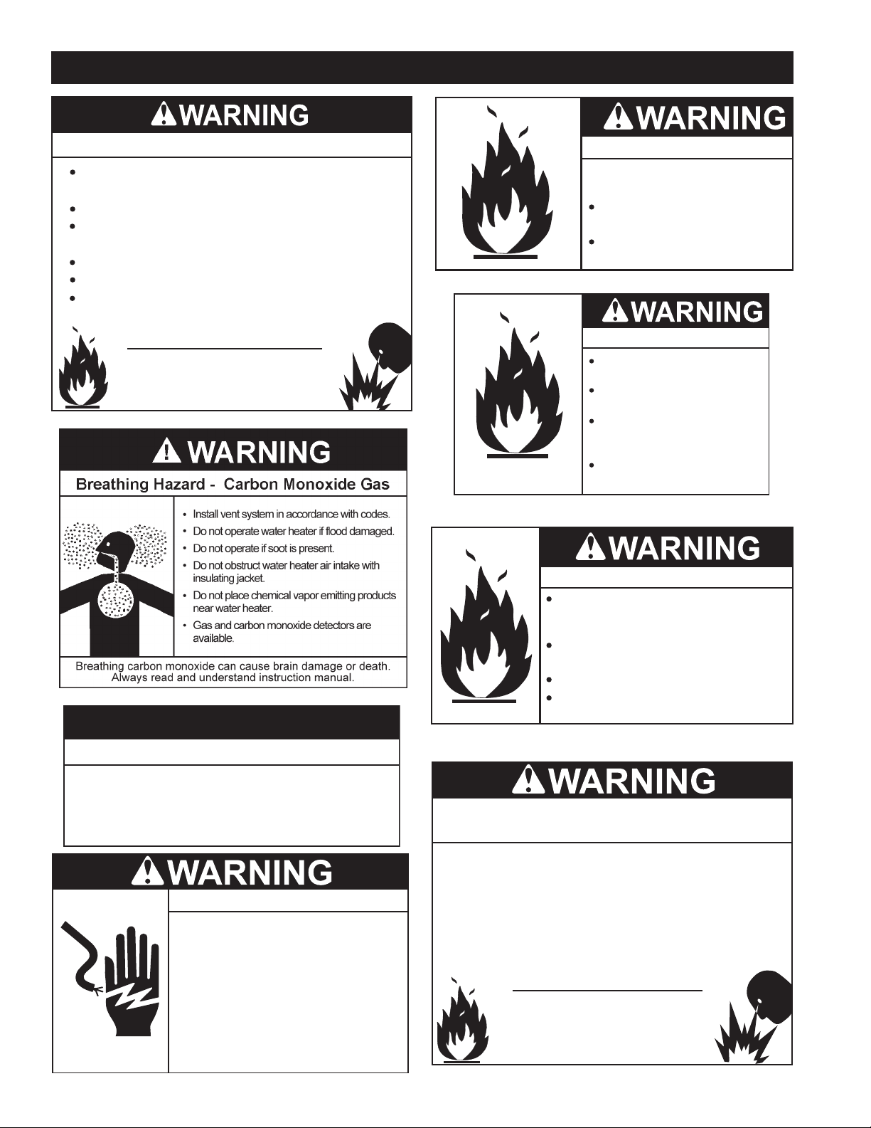
CAUTION
Fire or Explosion Hazard
Do not store or use gasoline or other flammable vapors and
liquids in the vicinity of this or any other appliance.
Avoid all ignition sources if you smell gas.
Do not expose water heater controls to excessive gas
pressure.
Use only the gas shown on the water heater rating label.
Maintain required clearances to combustibles.
Keep ignition sources away from faucets after extended
periods of non-use.
Read instruction manual before
installing, using or servicing
water heater.
Fire Hazard
For continued protection against
risk of fire:
Do not install water heater on
carpeted floor.
Do not operate water heater if
flood damaged.
Fire and Explosion Hazard
Use joint compound or Teflon tape
compatible with propane gas.
Leak test before placing the
water heater in operation.
Disconnect gas piping and main
gas shutoff valve before leak
testing.
Install sediment trap in
accordance with NFPA 54.
Property Damage Hazard
All water heaters eventually leak.
•
Do not install without adequate drainage.
•
Electrical Shock Hazard
Turn off power to the water heater
•
before performing any service.
Label all wires prior to disconnecting
•
when performing service. Wiring errors
can cause improper and dangerous
operation.
Verify proper operation after servicing.
•
Failure to follow these instructions can
•
result in personal injury or death.
Fire and Explosion Hazard
Do not use water heater with any gas
other than the gas shown on the rating
label.
Excessive gas pressure to gas valve can
cause serious injury or death.
Turn off gas lines during installation.
Contact a qualified installer or service
agency for installation and service.
Jumping out control circuits or components can
result in property damage, personal injury or death.
Service should only be performed by a qualified service
•
agent using proper test equipment.
Altering the water heater controls and/or wiring in any way
•
could result in permanent damage to the controls or water
heater and is not covered under the limited warranty.
Altering the water heater controls and/or wiring in any way
•
could result in altering the ignition sequence allowing gas to
flow to the main burner before the hot surface igniter is at
ignition temperature causing delayed ignition which can
cause a fire or explosion.
Any bypass or alteration of the water
heater controls and/or wiring will result
in voiding the water heater warranty.
4
GENERAL SAFETY INFORMATION
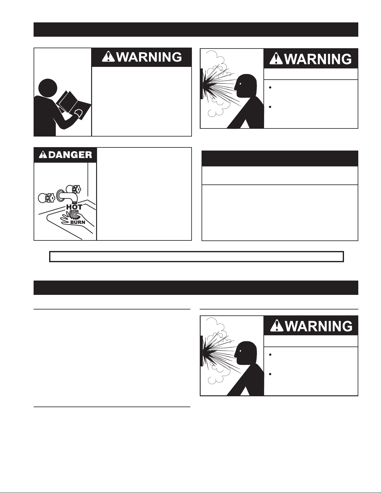
Read and understand this instruction
manual and the safety messages
herein before installing, operating or
servicing this water heater.
Failure to follow these instructions and
safety messages could result in death
or serious injury.
This manual must remain with the
water heater.
Water temperature over 125°F (52°C)
can cause severe burns instantly
resulting in severe injury or death.
Children, the elderly and the
physically or mentally disabled are at
highest risk for scald injury.
Feel water before bathing or
showering.
Temperature limiting devices such as
mixing valves must be installed
when required by codes and to
ensure safe temperatures at fixtures.
Explosion Hazard
Overheated water can cause
water tank explosion.
Properly sized temperature and
pressure relief valve must be
installed in the opening provided.
CAUTION
Improper installation, use and service may result
in property damage.
Do not operate water heater if flood damaged.
•
Inspect anode rods regularly, replace if damaged.
•
Install in location with drainage.
•
Fill tank with water before operation.
•
Properly sized thermal expansion tanks are required on all
•
closed water systems.
Refer to this manual for installation and service.
Verify the power to the water heater is turned off before performing any service procedures.
GENERAL SAFETY INFORMATION
PRECAUTIONS
DO NOT USE THIS water heater IF ANY PART HAS BEEN
UNDER WATER. Immediately call a qualified service agency
to inspect the water heater and to make a determination on
what steps should be taken next.
If the unit is exposed to the following, do not operate heater
until all corrective steps have been made by a qualified
service agency.
1. External re.
2. Damage.
3. Firing without water.
GROUNDING INSTRUCTIONS
This water heater must be grounded in accordance with the
National Electrical Code and/or local codes. These must be
followed in all cases.
This water heater must be connected to a grounded, permanent
wiring system; or an equipment grounding conductor must be
run with the circuit conductors and connected to the equipment
grounding terminal or lead on the water heater, see Figures 20
and 21.
HYDROGEN GAS FLAMMABLE
Explosion Hazard
Flammable hydrogen gases
may be present.
Keep all ignition sources away
from faucet when turning on
hot water.
Hydrogen gas can be produced in a hot water system served
by this water heater that has not been used for a long period of
time (generally two weeks or more). Hydrogen gas is extremely
ammable. To reduce the risk of injury under these conditions,
it is recommended that a hot water faucet served by this water
heater be opened for several minutes before using any electrical
appliance connected to the hot water system. If hydrogen is
present there will probably be an unusual sound such as air
escaping through the pipe as the water begins to ow. THERE
SHOULD BE NO SMOKING OR OPEN FLAME NEAR THE
FAUCET AT THE TIME IT IS OPEN.
5

INTRODUCTION
Thank You for purchasing this water heater. Properly installed
and maintained, it should give you years of trouble free service.
ABBREVIATIONS USED
Abbreviations found in this Instruction Manual include :
• ANSI - American National Standards Institute
• ASME - American Society of Mechanical Engineers
• AHRI - Air-Conditioning, Heating and Refrigeration Institute
• NEC - National Electrical Code
• NFPA - National Fire Protection Association
• UL - Underwriters Laboratory
• CSA - Canadian Standards Association
QUALIFICATIONS
QUALIFIED INSTALLER OR SERVICE AGENCY
Installation and service of this water heater requires ability
equivalent to that of a Qualied Agency (as dened by ANSI
below) in the eld involved. Installation skills such as plumbing,
air supply, venting, gas supply and electrical supply are required
in addition to electrical testing skills when performing service.
ANSI Z223.1 2006 Sec. 3.3.83: “Qualied Agency” - “Any
individual, rm, corporation or company that either in person or
through a representative is engaged in and is responsible for (a)
the installation, testing or replacement of gas piping or (b) the
connection, installation, testing, repair or servicing of appliances
and equipment; that is experienced in such work; that is familiar
with all precautions required; and that has complied with all the
requirements of the authority having jurisdiction.”
If you are not qualied (as dened by ANSI above) and licensed
or certied as required by the authority having jurisdiction
to perform a given task do not attempt to perform any of the
procedures described in this manual. If you do not understand
the instructions given in this manual do not attempt to perform
any procedures outlined in this manual.
START UP REQUIREMENTS
This product requires a formal Start-Up by an authorized
service/
start-up provider that has been approved by the manufacturer
for this specic product. Call 1-800-527-1953 to locate the
nearest authorized start-up provider and arrange a factory
start-up. Please provide as much notice as possible, preferably
2 weeks. Please have the model and serial number ready when
you call.
This start-up is required to activate the warranty and ensure
safe, efcient operation.
Warranty on this product is limited and could be void in the
event the unit is not installed per the instructions in this manual
and/or not started up by an authorized factory trained service/
start-up provider.
PREPARING FOR THE INSTALLATION
1. Read the “General Safety” section, page 4-5 of this manual
first and then the entire manual carefully. If you don’t follow
the safety rules, the water heater will not operate properly.
It could cause DEATH, SERIOUS BODILY INJURY AND/OR
PROPERTY DAMAGE.
This manual contains instructions for the installation, operation,
and maintenance of the gas-red water heater. It also contains
warnings throughout the manual that you must read and be
aware of. All warnings and all instructions are essential to the
proper operation of the water heater and your safety. Since we
cannot put everything on the rst few pages, READ THE ENTIRE
MANUAL BEFORE ATTEMPTING TO INSTALL OR OPERATE
THE WATER HEATER.
2. The installation must conform with these instructions and the
local code authority having jurisdiction. In the absence of local
codes, the installation must comply with the current editions
of the National Fuel Gas Code, ANSI Z223.1/NFPA 54 or CAN/
CSA-B149.1 the Natural Gas and Propane Installation Code.
All documents are available from the Canadian Standards
Association, 8501 East Pleasant Valley Road, Cleveland, OH
44131. NFPA documents are also available from the National
Fire Protection Association, 1 Batterymarch Park, Quincy, MA
02269.
3. If after reading this manual you have any questions or do
not understand any portion of the instructions, call the local
gas utility or the manufacturer whose name appears on the
rating plate.
4. Carefully plan the place where you are going to put the
water heater. Correct combustion, vent action, and vent pipe
installation are very important in preventing death from possible
carbon monoxide poisoning and res.
Exami n e the loc ation to en s u re th e wa t e r he a ter co m p l i e s wi t h
the “Locating the New Water Heater” section in this manual.
5. For California installation this water heater must be braced,
anchored, or strapped to avoid falling or moving during
an earthquake. See instructions for correct installation
procedures. Instructions may be obtained from California
Office of the State Architect, 400 P Street, Sacramento,
CA 95814.
6. Massachusetts Code requires this water heater to be installed in
accordance with Massachusetts 248-CMR 2.00: State Plumbing
Code and 248-CMR 5.00.
6

FEATURES AND COMPONENTS
HIGH LIMIT SWITCH
The dual bulb controller (g. 1) contains the high limit (energy cutoff)
sensor. The high limit switch interrupts main burner gas ow should
the water temperature reach 205°F (96°C).
In the event of high limit switch operation, the appliance cannot be
restarted unless the water temperature is reduced by at least 20°F
(11°C) and the high limit reset button on front of limit control (g.1)
is depressed.
Continued manual resetting of high limit control, preceded by higher
than usual water temperature is evidence of high limit switch operation.
The following is a possible reason for high limit switch operation:
• A malfunction in the thermostatic controls would allow the gas
control valve to remain open causing water temperature to
exceed the thermostat setting. The water temperature would
continue to rise until high limit switch operation.
Contact your dealer or service agent if continued high limit switch
operation occurs.
BAROMETRIC DRAFT CONTROL
The heater is equipped with a double acting barometric draft
control. This control assembly is factory adjusted to automatically
regulate the chimney draft imposed on the unit.
BAROMETRIC DRAFT CONTROL
FIGURE 3.
COMBUSTION CHAMBER OBSERVATION PORT
The combustion chamber observation access panel is located
above and to the left of the burner. A plug located under the
panel is inserted into the combustion chamber wall. See Figure
4. This plug should not be removed except, in rare cases, when
the combustion chamber requires cleaning or replacement.
DIGITAL THERMOSTAT
FIGURE 1.
ELECTRONIC IGNITION CONTROL
Each heater is equipped with a Honeywell ignition module. The
Direct Spark Ignition Control Module controls the ignition
sequence and gas control operation of the water heater.
MPLS., MN 55422
ASSEMBLED IN MEXICO
S8600M
CONTINUOUS RE-TRY
Explosion hazard. Can cause
serious injury or death.
This device can malfunction if
it gets wet. Never try to use a
device that has been wet - replace it.
IGNITION MODULE
100% SHUTOFF IP
90 SEC. TRIAL FOR IGNITION
24V, 60Hz
PV=1A MAX., MV=1A MAX
FIGURE 2.
If module has been used with
vent damper, It will only work
with damper connected.
FIGURE 4.
UNCRATING
Uncrate the heater by removing the outside mat and top locator.
The shipping pallet must be removed from the unit. It may be
possible to simply unbolt the base from the pallet and, with
the help of 2 or more persons, work the unit off the pallet.
Some units will be too heavy and will require the use of jacks
or lifting equipment to safely remove the pallet and move the
unit into position. Be careful when moving this heater. It will
tip over easily.
The heater is shipped with a draft control. The draft control is
shipped in a separate carton. It should be installed as received
without any alterations.
Discard the shipping crate and packaging cartons in an
appropriate manner.
7
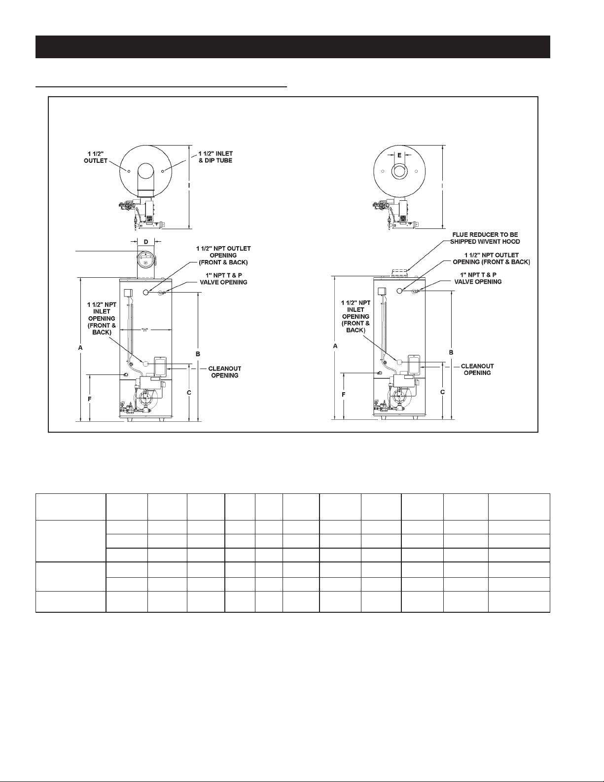
ROUGH IN DIMENSIONS
INSTALLATION CONSIDERATIONS
STANDARD BAROMETRIC DRAFT CONTROL
BTP MODELS
HORIZONTAL & DIRECT VENTING
BTPV MODELS
MAXIMUM TOTAL 75
EQUIVALENT FEET INTAKE
AND EXHAUST ALLOWED.
FIGURE 5.
TABLE 1 . MODELS BTP(V)-540(A) THROUGH BTP(V)-740(A)
Models A B C D E F G H I
80 3/4 73 32 1/4 9 6 26 1/2 93 29 1/2 48 1/2 1* 950
BTP(V)-540A
BTP(V)-650A
BTP(V)-740A 2,051 1,854 819 229 203 673 2,362 749 1,232 25.4 431 kg
*Minimum gas supply pipe is 1 1/4”, reference Table 11 for gas supply pipe size.
2,051 1,854 819 229 152 673 2,362 749 1,232 25.4 431 kg
80 3/4 73 32 1/4 9 8 26 1/2 93 29 1/2 48 1/2 1* 950
2,051 1,854 819 229 203 673 2,362 749 1,232 25.4 431 kg
80 3/4 73 32 1/4 9 8 26 1/2 93 29 1/2 48 1/2 1* 950
Gas
Conn.
Ship. Wt.
Approx.
8
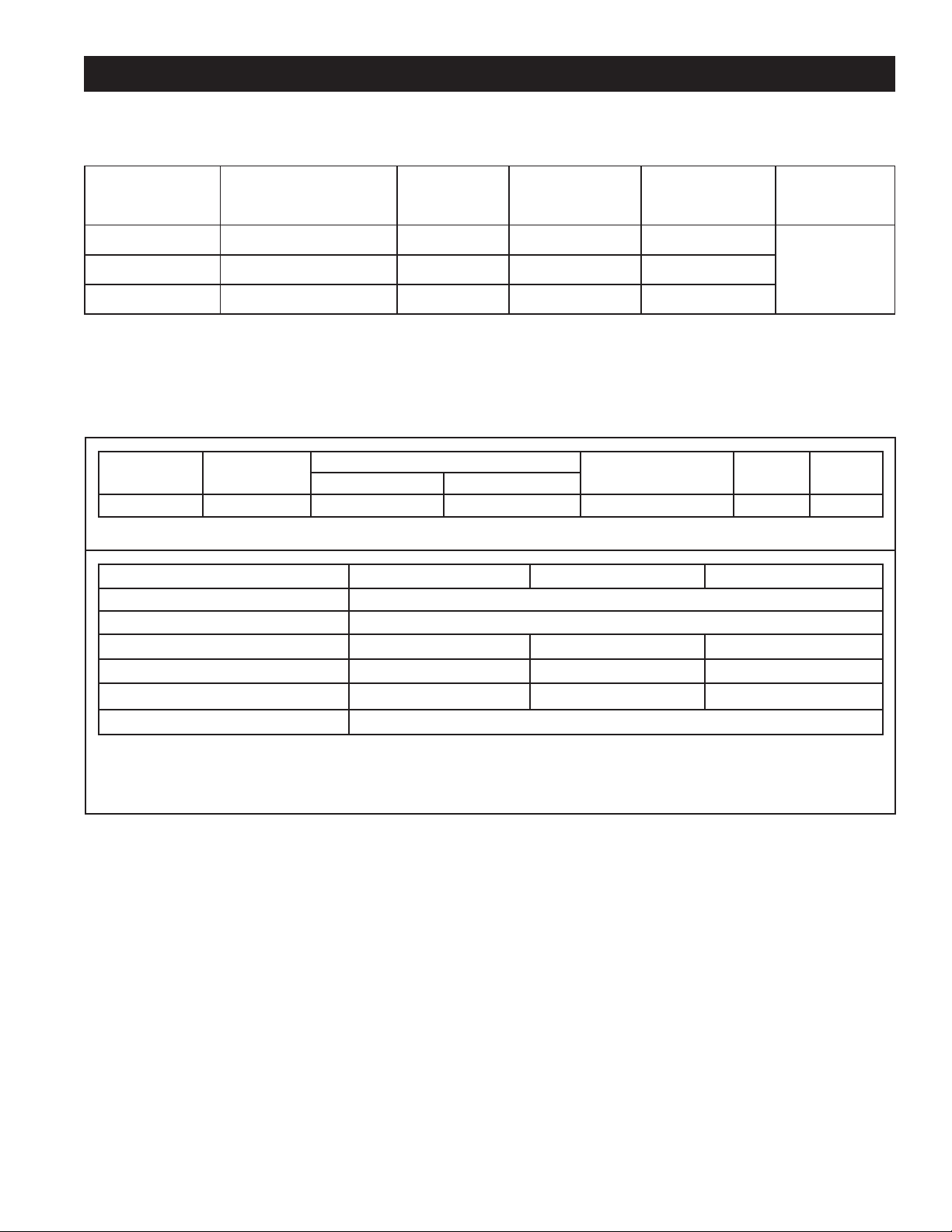
INSTALLATION CONSIDERATIONS
TABLE 2. HEATER PERFORMANCE DATA BTP MODELS
Storage
Capacity
Models
BTP(V)-540A
BTP(V)-650A
BTP(V)-740A
Models with letter “A” following the model number have the optional ASME tank construction.
* Based on 80% thermal efciency.
NOTE: To compensate for the effects of high altitude areas above 2000 feet, recovery ratings should be reduced approximately
4% for every 1000 feet above sea level.
U.S. Gals. (Litres)
85 (261)
85 (261)
85 (261)
Input Rating
BTU/HR.
Nat.
540,000 523.6 374
650,000 630 450
740,000 718 512
Recovery Rating
GPH
100°F Rise*
Recovery Rating
140°F Rise*
GPH
TABLE 3. GAS AND ELECTRICAL CHARACTERISTICS
Gas Supply Pressure
Model Type of Gas
All Models Natural 8.0" W.C. (2.0 kPa) 14" W.C. (3.48 kPa) 4.7" W.C. (1.18 kPa) 120/60 <5
* All models are available in Natural Gas only.
Model BTP(V)-540A BTP(V)-650A BTP(V)-750A
Min. Dynamic Gas Supply Line Pressure 8" w.c. (2 kPa) When heater is ON
Max. Static Gas Supply Line Pressure 14" w.c. (3.5 kPa) When heater is OFF
Gas Manifold Pressure 4.7" w.c.(1.1 kPa) (Ref. )* 4.7" w.c. 1.1 kPa) (R e f . ) * 4.7" w.c.(1.1 kPa) (Ref.)*
Gas Orice Size 1/2” 11/16” N/A
Air Inlet Damper Dial Setting 3** 4.5**
Combustion Emissions Range Flue Gas O2: 5 - 6.5%** (or CO2 reading 8-9%)
Gas Manifold Pressure Volts/Hz AmperesMinimum Maximum
Current Draw
120V
GOHz 1 Phase
6.0 Amps
5.6**
* Note: Flue gas excess O
operation or incomplete combustion. Final manifold pressure settings should be based on ue O
** Note: Air inlet damper setting needs to be adjusted at eld for direct vent and/or high elevation installations.
below 3% may cause combustion chamber premature failure; ue gas excess O2 above 7% may cause rough
2
9
/CO2 reading!
2
CAUTION
INSTALLATION CONSIDERATIONS
LOCATING THE WATER HEATER
Property Damage Hazard
All water heaters eventually leak.
•
Do not install without adequate drainage.
•
When installing the heater, consideration must be given to
proper location. Location selected should be as close to the
stack or chimney as practicable, with adequate air supply and
as centralized with the piping system as possible.
Fire or Explosion Hazard
Do not store or use gasoline or other flammable vapors and
liquids in the vicinity of this or any other appliance.
Avoid all ignition sources if you smell gas.
Do not expose water heater controls to excessive gas
pressure.
Use only the gas shown on the water heater rating label.
Maintain required clearances to combustibles.
Keep ignition sources away from faucets after extended
periods of non-use.
Read instruction manual before
installing, using or servicing
water heater.
Flammable items, pressurized containers or any other potential
re hazardous articles must never be placed on or adjacent to
the heater. Open containers or ammable material should not be
stored or used in the same room with the heater.
The heater must not be located in an area where it will be
subject to freezing.
Locate it near a oor drain. The heater should be located
in an area where leakage from heater or connections will
not result in damage to adjacent area or to lower oors of
the structure.
When such locations cannot be avoided, a suitable metal drain
pan should be installed under heater. Such pans should be
fabricated with sides at least 2” (50.8 mm) deep, with length
and width at least 2” (50.8 mm) greater than diameter of
heater and must be piped to an adequate drain. Pan must
not restrict combustion air ow.
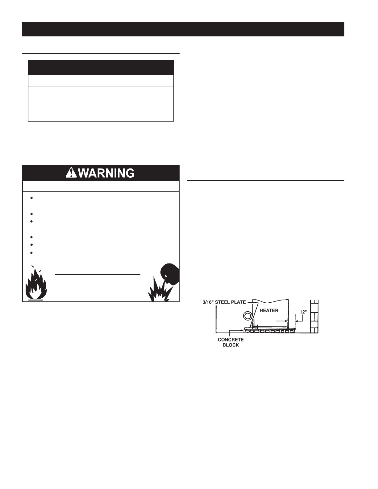
CLEARANCES
These heaters are designed for installation on non-combustible
ooring in an alcove with clearances to combustible construction
of 6” (152.4 mm) from the sides and rear, 24” (610 mm)
from the top with a 6” (152.4 mm) minimum between vent
pipe and ceiling.
Minimum clearance from ue pipe to combustible material is
6” (152.4 mm), see Figure 7.
Units which are to be installed on combustible ooring must
be supported by a full layer of hollow concrete blocks, from
8" to 12" thick and extending 12" (minimum) beyond the
heater in all directions. The concrete blocks must provide an
unbroken concrete surface under the heater with the hollows
running continuously and horizontally. A 3/16 inch steel plate
must cover the concrete blocks. See Figure 6.
There is a risk in using fuel burning appliances such as gas water
heaters in rooms, garages or other areas where gasoline, other
ammabl e liquids or engine driven equipment or vehicles are stored,
operated or repaired. Flammable vapors are heavy and travel
along the oor and may be ignited by the heater’s igniter or main
burner ames causing re or explosion. Some local codes permit
operation of gas appliances in such areas if they are installed
18" (457.2 mm) or more above the oor. This may reduce the risk
if location in such an area cannot be avoided.
Do not install this water heater directly on a carpeted oor. A re
hazard may result. Instead the water heater must be placed on a metal
or wood panel extending beyond the full width and depth by at least
3" (76.2 mm) in any direction. If the heater is installed in a carpeted
alcove, the entire oor shall be covered by the panel. Also, see the
DRAINING requirements in MAINTENANCE Section.
The heater shall be located or protected so it is not subject to physical
damage by a moving vehicle.
PROPER INSTALLATION ON COMBUSTIBLE FLOORING
FIGURE 6.
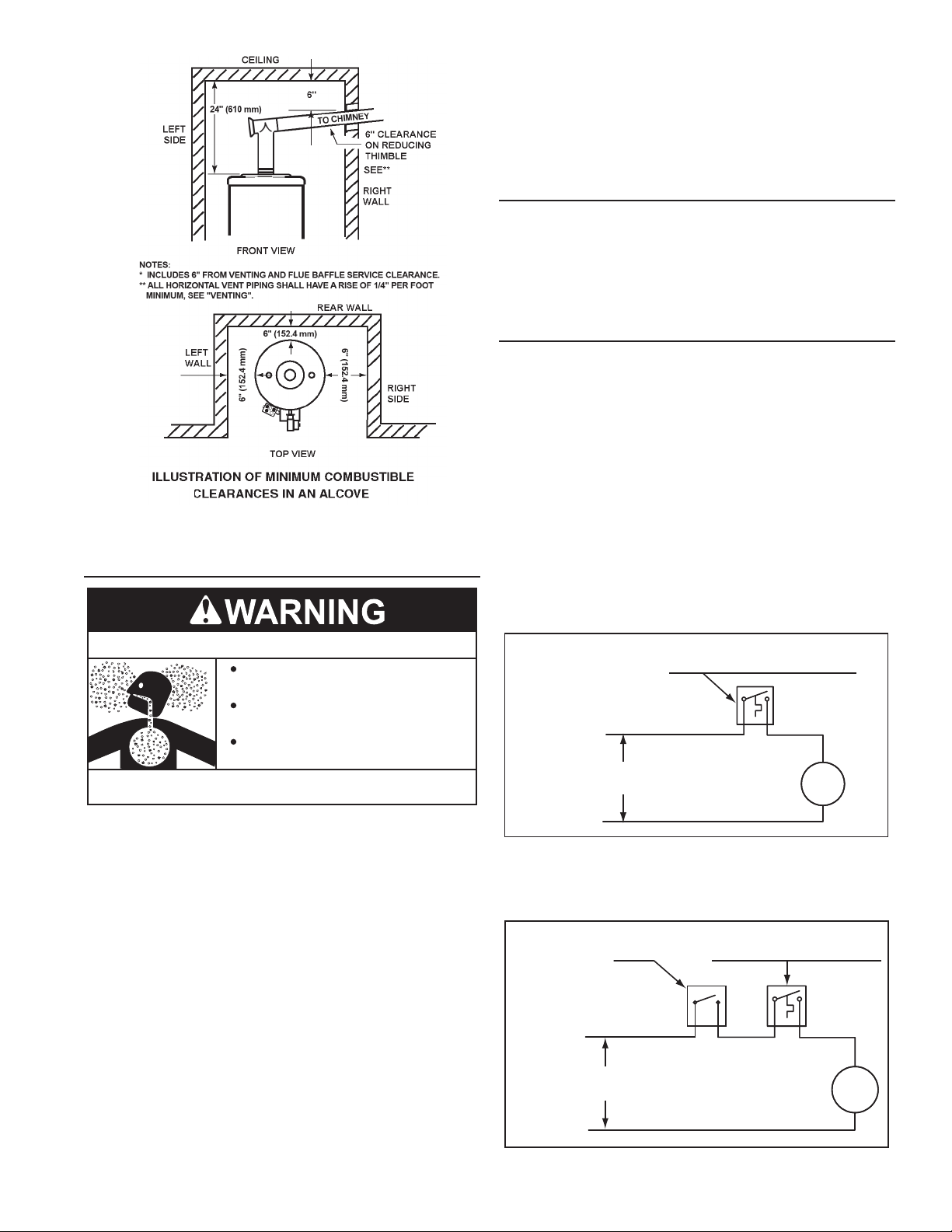
In all installations the minimum combustible clearances
from barometric draft control surface or vent piping shall be
6” (152 mm). Vent piping passing through a combustible wall
or ceiling must be a continuous run (no joints) and retain
6” (152 mm) clearance unless an approved reducing thimble
is used.
A service clearance of 30" (762 mm) should be maintained from
serviceable parts, such as relief valves, bafes, thermostats,
cleanout openings or drain valves.
10
CIRCULATING PUMP WIRING DIAGRAM
DISHWASHER LOOP WITH TOGGLE SWITCH
FIELD SUPPLIED TEMPERATURE
CONTROL INSTALLED IN THE
CIRCULATING LOOP RETURN LINE
DISHWASHER
TOGGLE
SWITCH
CIRC
PUMP
MOTOR
L1 HOT
L2 NEUTRAL
120 VAC
POWER
NOTE: USE SEPARATE 120 VAC POWER
SUPPLY FOR PUMP CIRCUIT. DO NOT SHARE
POWER WITH WATER HEATER AS THIS MAY
CAUSE ELECTRICAL LINE NOISE AND LEAD
TO ERRATIC CONTROL SYSTEM OPERATION.
FIGURE 7.
INSULATION BLANKET
Breathing Hazard - Carbon Monoxide Gas
Do not obstruct water heater air intake
with insulating blanket.
Gas and carbon monoxide detectors
are available.
Install water heater in accordance with
the instruction manual.
Breathing carbon monoxide can cause brain damage or
death. Always read and understand instruction manual.
Insulation blankets are available to the general public for
external use on gas water heaters but are not necessary
with these products. The purpose of an insulation blanket
is to reduce the standby heat loss encountered with storage
tank heaters. The water heaters covered by this manual meet
or exceed the Energy Policy Act standards with respect to
insulation and standby heat loss requirements, making an
insulation blanket unnecessary.
Should you choose to apply an insulation blanket to this
heater, you should follow these instructions. See the
Features and Components section of this manual for
identification of components mentioned below. Failure to
follow these instructions can restrict the air flow required for
proper combustion, potentially resulting in fire, asphyxiation,
serious personal injury or death.
• DO NOT apply insulation to the top of the water heater, as this
will interfere with safe operation of the draft control.
• DO NOT cover the gas control valve, thermostat or the
Temperature-Pressure Relief Valve.
• DO NOT allow insulation to come within 2” (5 cm) of the burners,
to prevent blockage of combustion air ow to the burners.
• DO NOT cover the instruction manual. Keep it on the side of
the water heater or nearby for future reference.
• DO obtain new warning and instruction labels from the
manufacturer for placement on the blanket directly over the
existing labels.
• DO inspect the insulation blanket frequently to make certain it
does not sag, thereby obstructing combustion air ow.
HARD WATER
Where hard water conditions exist, water softening or the
threshold type of water treatment is recommended. This will
protect the dishwashers, coffee urns, water heaters, water piping
and other equipment.
See the Maintenance Section in this manual for sediment and
lime scale removal procedures.
CIRCULATION PUMPS
A circulating pump is used when a system requires a circulating
loop or there is a storage tank used in conjunction with the water
heater. See Water Piping Diagrams in this manual for installation
location of circulating pumps.
See the Circulation Pump Wiring Diagrams in this manual for
electrical hookup information. Install in accordance with the
current edition of the National Electrical Code, NFPA 70 or the
Canadian Electrical Code, CSA C22.1.
All-bronze circulating pumps are recommended for used with
commercial water heaters.
Some circulating pumps are manufactured with sealed bearings
and do not require further lubrication. Some circulating pumps
must be periodically oiled. Refer to the pump manufacturer’s
instructions for lubrication requirements.
CIRCULATING PUMP WIRING DIAGRAM
STORAGE TANK OR BUILDING RECIRCULATION
FIELD SUPPLIED TEMPERATURE CONTROL
INSTALLED IN THE STORAGE TANK
NOTE: USE SEPARATE 120 VAC POWER
SUPPLY FOR PUMP CIRCUIT. DO NOT
SHARE POWER WITH WATER HEATER AS THIS
MAY CAUSE ELECTRICAL LINE NOISE AND
LEAD TO ERRATIC CONTROL SYSTEM
OPERATION.
L1 HOT
L2 NEUTRAL
120 VAC
POWER
CIRCULATING PUMP WIRING DIAGRAM
DISHWASHER LOOP WITH TOGGLE SWITCH
DISHWASHER
TOGGLE
SWITCH
NOTE: USE SEPARATE 120 VAC POWER
SUPPLY FOR PUMP CIRCUIT. DO NOT SHARE
POWER WITH WATER HEATER AS THIS MAY
CAUSE ELECTRICAL LINE NOISE AND LEAD
TO ERRATIC CONTROL SYSTEM OPERATION.
L1 HOT
L2 NEUTRAL
11
120 VAC
POWER
OR CIRCULATING LOOP RETURN LINE
CIRC
PUMP
MOTOR
FIGURE 8.
FIELD SUPPLIED TEMPERATURE
CONTROL INSTALLED IN THE
CIRCULATING LOOP RETURN LINE
CIRC
PUMP
MOTOR
FIGURE 9.
HIGH ALTITUDE INSTALLATIONS
Fire and Explosion Hazard
Under no circumstances should the
input exceed the rate shown on the
water heater’s rating label.
Overfiring could result in fire or
explosion.
Gas and carbon monoxide detectors are
available.
Breathing Hazard - Carbon Monoxide Gas
Under no circumstances should
the input exceed the rate shown
on the water heater’s rating label.
Overfiring could result in damage to
the water heater and sooting.
Your A.O. Smith water heater has been designed to operate at
altitudes below 2000 Ft. (609.6 m). For appliance installation
locations with elevations above 2000 Ft. (609.6 m), special
considerations need to be taken. Adjustments for high altitude
can only be made by an A.O. Smith authorized BTP Start-up
Agent. To ensure your water heater operates properly at high
elevation, an A.O. Smith authorized BTP Start-up Agent will
readjust the air-intake damper setting and the gas manifold
pressure (if required).
NOTE: Some gas utility companies derate the heating value
of the supplied gas at high elevation. Your authorized star t-up
agent must adjust for actual heating value of the gas at the time
of start up.
Gas and carbon monoxide detectors
are available.
Breathing carbon monoxide can cause brain damage or
death. Always read and understand instruction manual.
12
INSTALLATION REQUIREMENTS
GAS SUPPLY SYSTEMS
Low pressure building gas supply systems are defined as those
systems that cannot under any circumstances exceed 14”
W.C. (1/2 PSI Gauge). These systems do not require pressure
regulation. Measurements should be taken to insure that gas
pressures are stable and fall within the requirements stated on
the water heater rating plate. Readings should be taken with
all gas burning equipment off (static pressure) and with all gas
burning equipment running at maximum rate (dynamic pressure).
The gas supply pressure must be stable within 1.5” W.C.
from static to dynamic pressure to provide good performance.
Pressure drops that exceed 1.5” W.C. may cause rough starting,
noisy combustion or nuisance outages. Increases or spikes
in static pressure during off cycles may cause failure to ignite
or in severe cases damage to appliance gas valves. If your
low pressure system does NOT meet these requirements, the
installer is responsible for the corrections.
High Pressure building supply systems use pressures that
exceed 14” W.C. (1/2 PSI Gauge). These systems must use eld
supplied regulators to lower the gas pressure to less than 14”
W.C. (1/2 PSI Gauge). Water heaters require gas regulators that
are properly sized for the water heater input and deliver the rating
plate specied pressures. Gas supply systems where pressure
exceeds 5 PSI often require multiple regulators to achieve desired
pressures. Systems in excess of 5 PSI building pressure should
be designed by gas delivery professionals for best performance.
Water heaters connected to gas supply systems that exceed 14”
W.C. (1/2 PSI Gauge) at any time must be equipped with a gas
supply regulator.
All models require a minimum gas supply pressure of 8.0" W.C.
for natural gas and propane gas. The minimum supply pressure
is measured while gas is owing (dynamic pressure). The supply
pressure should never fall below 8.0" W.C. for natural gas. The
supply pressure should be measured with all gas red appliances
connected to the common main ring at full capacity. If the supply
pressure drops more than 1.5” W.C. as gas begins to ow to the
water heater then the supply gas system including the gas line and/
or the gas regulator may be restricted or undersized. See Supply
Gas Regulator section and Gas Piping section of this manual. The
gas valve on all models has a maximum gas supply pressure limit
of 14” W.C. The maximum supply pressure is measured while gas
is not owing (static pressure).
SUPPLY GAS REGULATOR
The maximum allowable gas supply pressure for this water heater is
14" W.C. (3.48 kPa). Install a positive lock-up gas pressure regulator
in the gas supply line if inlet gas pressure can exceed 14" W.C.
(3.48 kPa) at any time. Regulators must be sized/used according to
manufacturer’s specications.
If a positive lock-up regulator is required follow these instructions:
1. Positive lock-up gas pressure regulators must be rated at or above
the input Btu/hr rating of the water heater they supply.
2. Positive lock-up gas pressure regulator(s) should be installed no closer
than 3 equivalent feet (1 meter) and no farther than 8 equivalent
feet (2.4 meters) from water heater’s inlet gas connection.
3. After installing the positive lock-up gas pressure regulator(s), an
initial nominal supply pressure setting of 8.0" W.C. (2 kPa) while
water heater is operating is recommended and will generally
provide good water heater operation. Some additional adjustment
maybe required later to maintain a steady gas supply pressure.
4. When installing multiple water heaters in the same gas supply
system it is recommended that individual positive lock-up gas
pressure regulators be installed at each unit.
POWER SUPPLY
The water heaters covered in this manual require a 120 VAC,
1Ø (single phase), 60Hz, 15 amp power supply and must also
be electrically grounded in accordance with local codes or, in the
absence of local codes, with the National Electrical Code, ANSI/
NFPA 70 or the Canadian Electrical Code, CSA C22.1.
WATER TEMPERATURE CONTROL AND MIXING VALVES
Water temperature over 125°F (52°C)
can cause severe burns instantly
resulting in severe injury or death.
Children, the elderly and the
physically or mentally disabled are at
highest risk for scald injury.
Feel water before bathing or showering.
Temperature limiting devices such as
mixing valves must be installed
when required by codes and to
ensure safe temperatures at fixtures.
Water heated to a temperature which will satisfy clothes washing, dish
washing, and other sanitizing needs can scald and cause permanent
injury upon contact. Short repeated heating cycles caused by small
hot water uses can cause temperatures at the point of use to exceed
the water heater’s temperature setting by up to 20°F (11°C).
Some people are more likely to be permanently injured by hot water
than others. These include the elderly, children, the inrm and the
physically/mentally disabled. Table 4 shows approximate time-to-burn
relationship for normal adult skin. If anyone using hot water provided
by the water heater being installed ts into one of these groups or if
there is a local code or state law requiring a certain water temperature
at the point of use, then special precautions must be taken.
In addition to using the lowest possible temperature setting that
satises the demand of the application a Mixing Valve should be
installed at the water heater (see Figure 10) or at the hot water taps
to further reduce system water temperature.
Mixing valves are available at plumbing supply stores. Consult a
Qualied Installer or Service Agency. Follow mixing valve manufacturer’s
instructions for installation of the valves.
TABLE 4.
Water Temperature °F
110
116 (pain threshold)
116 35 minutes 45 minutes
122 1 minute 5 minutes
131 5 seconds 25 seconds
140 2 seconds 5 seconds
149 1 second 2 seconds
154 instantaneous 1 second
(U.S. Government Memorandum, C.P.S.C., Peter L. Armstrong, Sept. 15,1978)
Time for 1st Degree Burn
(Less Severe Burns)
(normal shower temp.)
Time for Permanent Burns
2nd & 3rd Degree
(Most Severe Burns)
13
HOT WATER
OUTLET
TEMPERED WATER
OUTLET
12” TO 15”
(30-38 cm)
A properly sized thermal expansion tank must be installed on
all closed systems to control the harmful effects of thermal
expansion. Contact a local plumbing service agency to have a
thermal expansion tank installed.
See Water Line Connections on page 24 and the Water Piping
Diagrams beginning on page 41.
TEMPERATURE-PRESSURE RELIEF VALVE
COLD
WATER
INLET
CHECK
VALV E
TO TANK
INLET
CHECK
VALV E
MIXING
VALV E
FIGURE 10.
DISHWASHING MACHINES
All dishwashing machines meeting the National Sanitation
Foundation requirements are designed to operate with water
flow pressures between 15 and 25 pounds per square inch
(103 kPa and 173 kPa). Flow pressures above 25 pounds
per square inch (173 kPa), or below 15 pounds per square
inch (103 kPa), will result in improperly sanitized dishes.
Where pressures are high, a water pressure reducing or flow
regulating control valve should be used in the 180°F (82°C)
line to the dishwashing machine and should be adjusted to
deliver water pressure between these limits.
The National Sanitation Foundation also recommends
circulation of 180°F (82°C) water. The circulation flow rate
should be just enough to provide 180°F (82°C) water at the
point of take-off to the dishwashing machine.
Adjust flow by throttling a full port ball valve installed in
the circulating line on the outlet side of the pump. Never
throttle flow on the suction side of a pump. See Water Piping
Diagrams in this manual.
CLOSED WATER SYSTEMS
Water supply systems may, because of code requirements or
such conditions as high line pressure, among others, have
installed devices such as pressure reducing valves, check
valves, and back flow preventers. Devices such as these
cause the water system to be a closed system.
THERMAL EXPANSION
As water is heated, it expands (thermal expansion). In a
closed system the volume of water will grow when it is heated.
As the volume of water grows there will be a corresponding
increase in water pressure due to thermal expansion. Thermal
expansion can cause premature tank failure (leakage). This
type of failure is not covered under the limited warranty.
Thermal expansion can also cause intermittent TemperaturePressure Relief Valve operation: water discharged from the
valve due to excessive pressure build up. This condition is
not covered under the limited warranty. The TemperaturePressure Relief Valve is not intended for the constant relief
of thermal expansion.
Explosion Hazard
Temperature-Pressure Relief Valve
must comply with ANSI Z21.22CSA 4.4 and ASME code.
Properly sized temperaturepressure relief valve must be
installed in opening provided.
Can result in overheating and
excessive tank pressure.
Can cause serious injury or death.
This water heater is provided with a properly rated/sized and certied
combination Temperature-Pressure Relief Valve (T&P valve) by
the manufacturer. The valve is certied by a nationally recognized
testing laboratory that maintains periodic inspection of production
of listed equipment of materials as meeting the requirements for
Pressure Relief Valves for Hot Water Supply Systems, ANSI Z21.22
• CSA 4.4, and the code requirements of ASME.
If replaced, the new T&P valve must meet the requirements
of local codes, but not less than a combination TemperaturePressure Relief Valve rated/sized and certied as indicated in
the above paragraph. The new valve must be marked with a
maximum set pressure not to exceed the marked hydrostatic
working pressure of the water heater (150 psi = 1,035 kPa) and
a discharge capacity not less than the water heater Btu/hr or kW
input rate as shown on the water heater’s model rating label.
NOTE: In addition to the factory installed Temperature-Pressure
Relief Valve on the water heater, each remote storage tank that
may be installed and piped to a water heating appliance must also
have its own properly sized, rated and approved Temperature-
Pressure Relief Valve installed. Call the toll free technical
support phone number listed on the back cover of this manual
for technical assistance in sizing a Temperature-Pressure Relief
Valve for remote storage tanks.
For safe operation of the water heater, the Temperature-Pressure
Relief Valve must not be removed from its designated opening
nor plugged. The Temperature-Pressure Relief Valve must be
installed directly into the tting of the water heater designed for
the pressure relief valve . Install discharge piping so that any
discharge will exit the pipe within 6 inches (15.2 cm) above an
adequate oor drain, or external to the building. In cold climates
it is recommended that it be terminated at an adequate drain
inside the building. Be certain that no contact is made with any
live electrical part. The discharge opening must not be blocked
or reduced in size under any circumstances. Excessive length,
over 30 feet (9.14 m), or use of more than four elbows can cause
restriction and reduce the discharge capacity of the valve.
14
No valve or other obstruction is to be placed between the
CAUTION
Temperature-Pressure Relief Valve and the tank. Do not connect
discharge piping directly to the drain unless a 6” (15.2 cm)
air gap is provided. To prevent bodily injury, hazard to life, or
property damage, the relief valve must be allowed to discharge
water in adequate quantities should circumstances demand. If
the discharge pipe is not connected to a drain or other suitable
means, the water ow may cause property damage.
Water Damage Hazard
CONTAMINATED AIR
Breathing Hazard - Carbon Monoxide Gas
Install water heater in accordance with
the Instruction Manual and NFPA 54 or
CAN/CSA-B149.1.
To avoid injury, combustion and ventilation
air must be taken from outdoors.
Do not place chemical vapor emitting
products near water heater.
Temperature-Pressure Relief Valve discharge
•
pipe must terminate at adequate drain.
T&P Valve Discharge Pipe Requirements:
• Shall not be smaller in size than the outlet pipe size of the
valve, or have any reducing couplings or other restrictions.
• Shall not be plugged or blocked.
• Shall not be exposed to freezing temperatures.
• Shall be of material listed for hot water distribution.
• Shall be installed so as to allow complete drainage of both
the Temperature-Pressure Relief Valve and the discharge
pipe.
• Must terminate a maximum of six inches above a oor
drain or external to the building. In cold climates, it is
recommended that the discharge pipe be terminated at an
adequate drain inside the building.
• Shall not have any valve or other obstruction between the
pressure relief valve and the drain.
Burn hazard.
Hot water discharge.
Breathing carbon monoxide can cause brain damage or
death. Always read and understand instruction manual.
Corrosion of the ue ways and vent system may occur if air for
combustion contains certain chemical vapors. Such corrosion
may result in failure and risk of asphyxiation.
Combustion air that is contaminated can greatly diminish the life
span of the water heater and water heater components such as
hot surface igniters and burners. Propellants of aerosol sprays,
beauty shop supplies, water softener chemicals and chemicals
used in dry cleaning processes that are present in the combustion,
ventilation or ambient air can cause such damage.
Do not store products of this sort near the water heater. Air which
is brought in contact with the water heater should not contain any
of these chemicals. If necessary, uncontaminated air should be
obtained from remote or outdoor sources. The limited warranty
is voided when failure of water heater is due to a corrosive
atmosphere. (See limited warranty for complete terms and
conditions).
AIR REQUIREMENTS
Breathing Hazard - Carbon Monoxide Gas
Keep clear of TemperaturePressure Relief Valve
discharge outlet.
The Temperature-Pressure Relief Valve must be manually operated
at least twice a year. Caution should be taken to ensure that (1) no
one is in front of or around the outlet of the Temperature-Pressure
Relief Valve discharge line, and (2) the water manually discharged
will not cause any bodily injury or property damage because
the water may be extremely hot. If after manually operating the
valve, it fails to completely reset and continues to release water,
immediately close the cold water inlet to the water heater, follow the
draining instructions in this manual, and replace the TemperaturePressure Relief Valve with a properly rated/sized new one.
NOTE: The purpose of a Temperature-Pressure Relief Valve is to
prevent excessive temperatures and pressures in the storage tank.
The T&P valve is not intended for the constant relief of thermal
expansion. A properly sized thermal expansion tank must be
installed on all closed systems to control thermal expansion, see
Closed Water Systems and Thermal Expansion on page 14.
If you do not understand these instructions or have any questions
regarding the Temperature-Pressure Relief Valve call the toll
free number listed on the back cover of this manual for technical
assistance.
Install water heater in accordance with
the Instruction Manual and NFPA 54 or
CAN/CSA-B149.1.
To avoid injury, combustion and ventilation
air must be taken from outdoors.
Do not place chemical vapor emitting
products near water heater.
Breathing carbon monoxide can cause brain damage or
death. Always read and understand instruction manual.
For safe operation an adequate supply of fresh uncontaminated
air for combustion and ventilation must be provided.
An insufcient supply of air can cause recirculation of combustion
products resulting in contamination that may be hazardous to
life. Such a condition often will result in a yellow, luminous burner
ame, causing sooting of the combustion chamber, burners and
ue tubes and creates a risk of asphyxiation.
Do not install the water heater in a conned space unless an
adequate supply of air for combustion and ventilation is brought
in to that space using the methods described in the Conned
Space section that follows.
Never obstruct the ow of ventilation air. If you have any doubts
or questions at all, call your gas supplier. Failure to provide the
proper amount of combustion air can result in a re or explosion
and cause property damage, serious bodily injury or death.
15
UNCONFINED SPACE
An Unconned Space is one whose volume IS NOT LESS THAN
50 cubic feet per 1,000 Btu/hr (4.8 cubic meters per kW) of the
total input rating of all appliances installed in the space. Rooms
communicating directly with the space, in which the appliances
are installed, through openings not furnished with doors, are
considered a part of the unconned space.
Makeup air requirements for the operation of exhaust fans,
kitchen ventilation systems, clothes dryers and replaces shall
also be considered in determining the adequacy of a space to
provide combustion, ventilation and dilution air.
UNUSUALLY TIGHT CONSTRUCTION
In unconned spaces in buildings, inltration may be adequate
to provide air for combustion, ventilation and dilution of ue
gases. However, in buildings of unusually tight construction (for
example, weather stripping, heavily insulated, caulked, vapor
barrier, etc.) additional air must be provided using the methods
described in the Conned Space section that follows.
CONFINED SPACE
A Conned Space is one whose volume is less than 50 cubic
feet per 1,000 Btu/hr (4.8 cubic meters per kW) of the total input
rating of all appliances installed in the space.
Openings must be installed to provide fresh air for combustion,
ventilation and dilution in conned spaces. The required size for
the openings is dependent on the method used to provide fresh
air to the conned space and the total Btu/hr input rating of all
appliances installed in the space.
DIRECT VENT APPLIANCES
Appliances installed in a Direct Vent conguration that derive all
air for combustion from the outdoor atmosphere through sealed
intake air piping are not factored in the total appliance input Btu/
hr calculations used to determine the size of openings providing
fresh air into conned spaces.
EXHAUST FANS
Where exhaust fans are installed, additional air shall be provided
to replace the exhausted air. When an exhaust fan is installed
in the same space with a water heater, sufcient openings to
provide fresh air must be provided that accommodate the
requirements for all appliances in the room and the exhaust fan.
Undersized openings will cause air to be drawn into the room
through the water heater’s vent system causing poor combustion.
Sooting, serious damage to the water heater and the risk of re
or explosion may result. It can also create a risk of asphyxiation.
LOUVERS AND GRILLES
The free areas of the fresh air openings in the instructions that
follow do not take in to account the presence of louvers, grilles or
screens in the openings.
The required size of openings for combustion, ventilation and
dilution air shall be based on the “net free area” of each opening.
Where the free area through a design of louver or grille or screen
is known, it shall be used in calculating the size of opening
required to provide the free area specied. Where the louver and
grille design and free area are not known, it shall be assumed
that wood louvers will have 25% free area and metal louvers and
grilles will have 75% free area. Non motorized louvers and grilles
shall be xed in the open position.
VENTING INSTALLATION
FRESH AIR OPENINGS FOR CONFINED SPACES
The following instructions shall be used to calculate the size,
number and placement of openings providing fresh air for
combustion, ventilation and dilution in conned spaces. The
illustrations shown in this section of the manual are a reference
for the openings that provide fresh air into conned spaces
only. DO NOT refer to these illustrations for the purpose of vent
installation. See Venting Installation on pages 17 through 23 for
complete venting installation instructions.
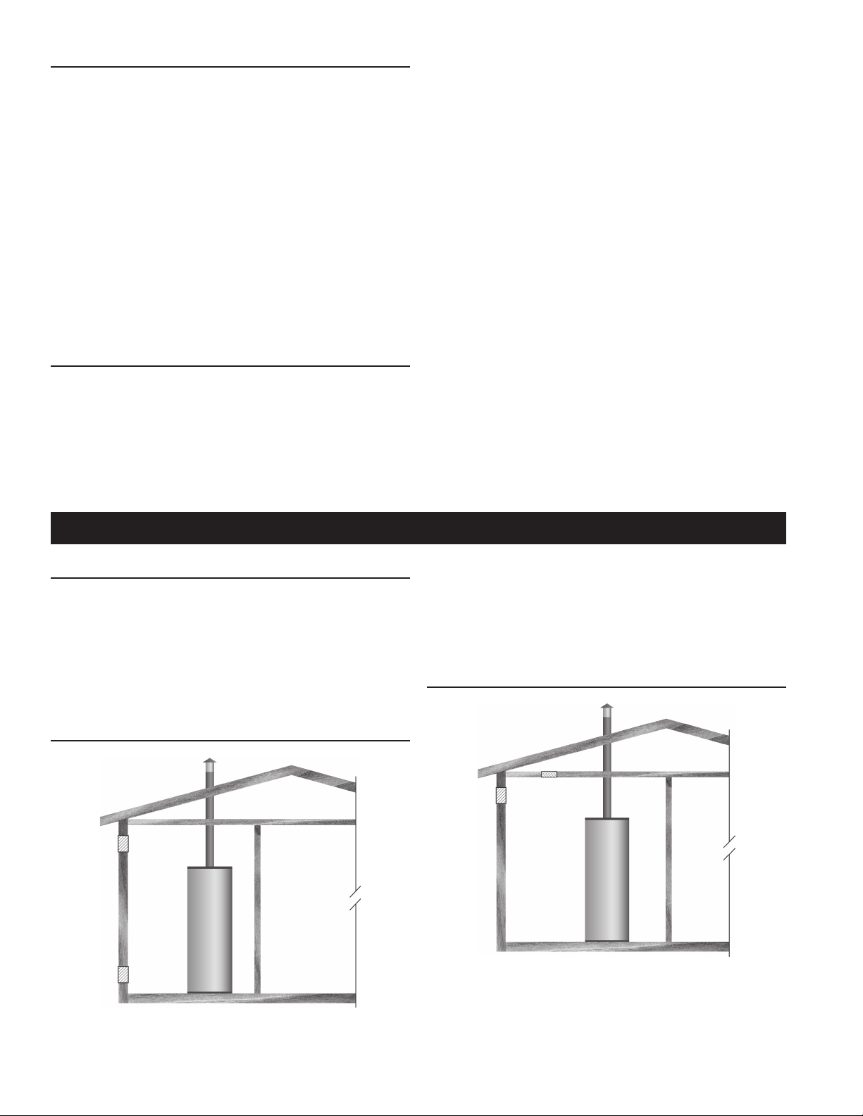
OUTDOOR AIR THROUGH TWO OPENINGS
and one commencing within 12 inches (300 mm) of the bottom of
the enclosure. The openings shall communicate directly with the
outdoors. See Figure 11.
Each opening shall have a minimum free area of 1 square inch
per 4,000 Btu/hr (550 mm
of all appliances installed in the enclosure. Each opening shall
not be less than 100 square inches (645 cm
2
per kW) of the aggregate input rating
2
).
OUTDOOR AIR THROUGH ONE OPENING
FIGURE 11.
The conned space shall be provided with two permanent
openings, one commencing within 12 inches (300 mm) of the top
FIGURE 12.
Alternatively a single permanent opening, commencing within 12
inches (300 mm) of the top of the enclosure, shall be provided.
See Figure 11. The water heater shall have clearances of at
least 1 inch (25 mm) from the sides and back and 6 inches (l50
mm) from the front of the water heater. The opening shall directly
communicate with the outdoors or shall communicate through a
16
vertical or horizontal duct to the outdoors or spaces that freely
communicate with the outdoors and shall have a minimum free
area of the following:
2
1. 1 square inch per 3000 Btu/hr (733 mm
per kW) of the total
input rating of all appliances located in the enclosure, and
2. Not less than the sum of the areas of all vent connectors
in the space.
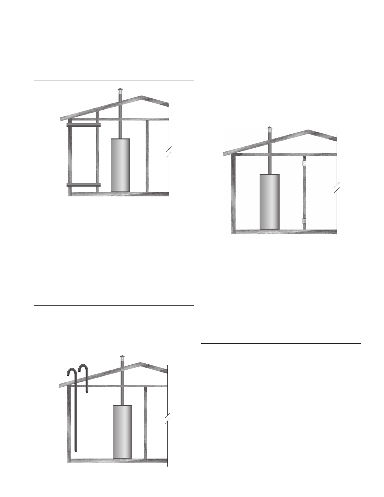
OUTDOOR AIR THROUGH TWO HORIZONTAL DUCTS
FIGURE 13.
The conned space shall be provided with two permanent
horizontal ducts, one commencing within 12 inches (300 mm)
of the top and one commencing within 12 inches (300 mm)
of the bottom of the enclosure. The horizontal ducts shall
communicate directly with the outdoors. See Figure 13.
Each duct opening shall have a minimum free area of 1 square
inch per 2,000 Btu/hr (1100 mm2 per kW) of the aggregate input
rating of all appliances installed in the enclosure.
When ducts are used, they shall be of the same cross sectional
area as the free area of the openings to which they connect.
The minimum dimension of rectangular air ducts shall be not
less than 3 inches.
OUTDOOR AIR THROUGH TWO VERTICAL DUCTS
The illustrations shown in this section of the manual are a
reference for the openings that provide fresh air into conned
spaces only.
Do not refer to these illustrations for the purpose of vent
installation. See Venting Installation on pages 17-18 for complete
venting installation instructions.
FIGURE 14.
The conned space shall be provided with two permanent vertical
ducts, one commencing within 12 inches (300 mm) of the top and
one commencing within 12 inches (300 mm) of the bottom of the
enclosure. The vertical ducts shall communicate directly with the
outdoors. See Figure 14.
Each duct opening shall have a minimum free area of 1 square
inch per 4,000 Btu/hr (550 mm
2
per kW) of the aggregate input
rating of all appliances installed in the enclosure.
When ducts are used, they shall be of the same cross sectional
area as the free area of the openings to which they connect.
The minimum dimension of rectangular air ducts shall be not less
than 3" (76.2 mm).
AIR FROM OTHER INDOOR SPACES
FIGURE 15.
The conned space shall be provided with two permanent
openings, one commencing within 12 inches (300 mm) of the top
and one commencing within 12 inches (300 mm) of the bottom of
the enclosure. See Figure 15.
Each opening shall communicate directly with an additional
room(s) of sufcient volume so that the combined volume of all
spaces meets the criteria for an Unconned Space.
Each opening shall have a minimum free area of 1 square inch
per 1,000 Btu/hr (2200 mm2 per kW) of the aggregate input rating
of all appliances installed in the enclosure. Each opening shall
not be less than 100 square inches (645 cm
2
).
VENTING
THE INSTRUCTIONS IN THIS SECTION ON VENTING MUST
BE FOLLOWED TO AVOID CHOKED COMBUSTION OR
RECIRCULATION OF FLUE GASES. SUCH CONDITIONS
CAUSE SOOTING OR RISKS OF FIRE AND ASPHYXIATION.
Heater must be protected from freezing downdrafts.
Remove all soot or other obstructions from the chimney that will
retard a free draft.
Type B venting is recommended with these heaters.
This water heater must be vented in compliance with all local
codes, the current revision of the National Fuel Gas Code
(ANSI-Z223.1) and with the Category I Venting Tables.
If any part of the vent system is exposed to ambient temperatures
below 40°F (4.4°C) it must be insulated to prevent condensation.
• Do not connect the heater to a common vent or chimney with
solid fuel burning equipment. This practice is prohibited by
many local building codes as is the practice of venting gas
red equipment to the duct work of ventilation systems.
17
• Where a separate vent connection is not available and the
vent pipe from the heater must be connected to a common
vent with an oil burning furnace, the vent pipe should enter
the smaller common vent or chimney at a point above the
large vent pipe.
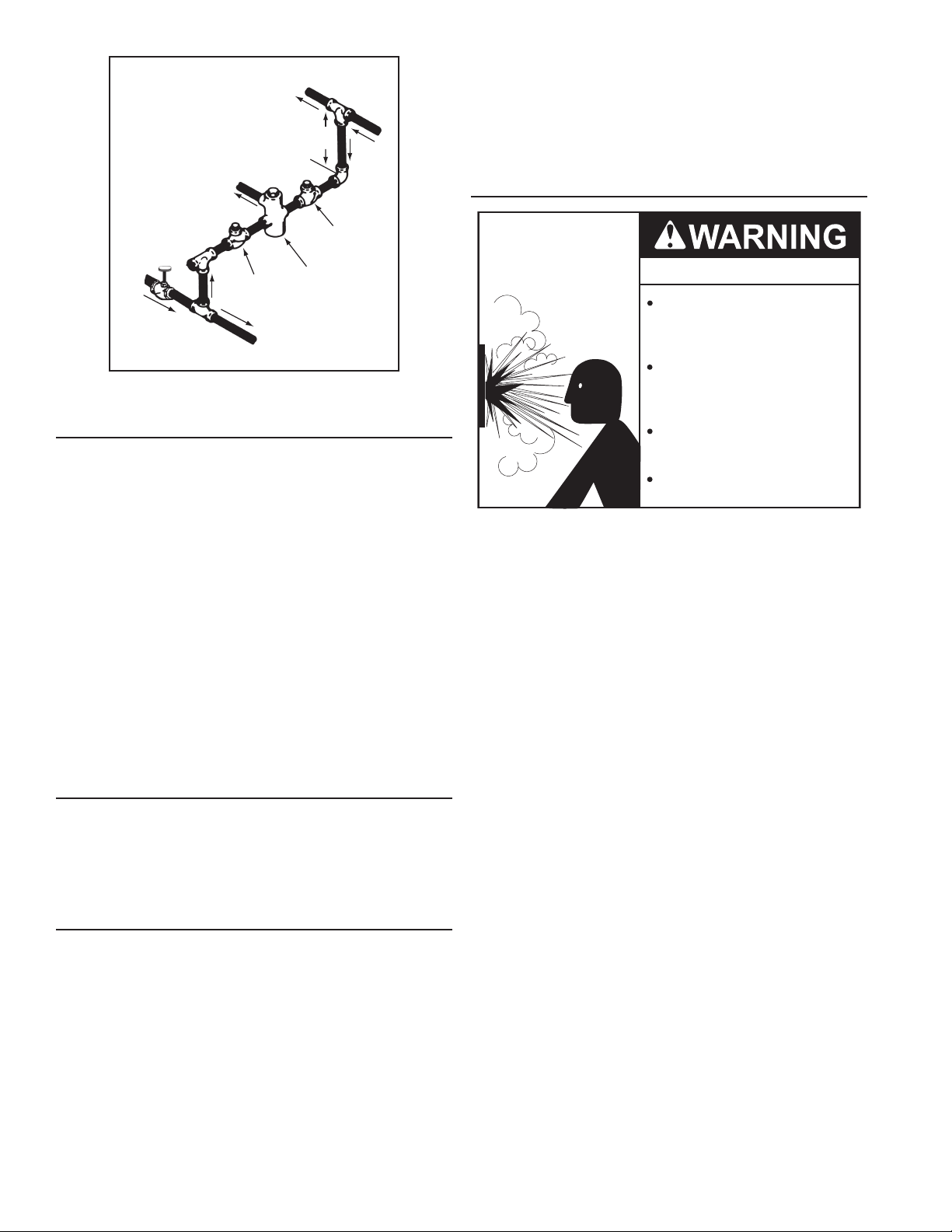
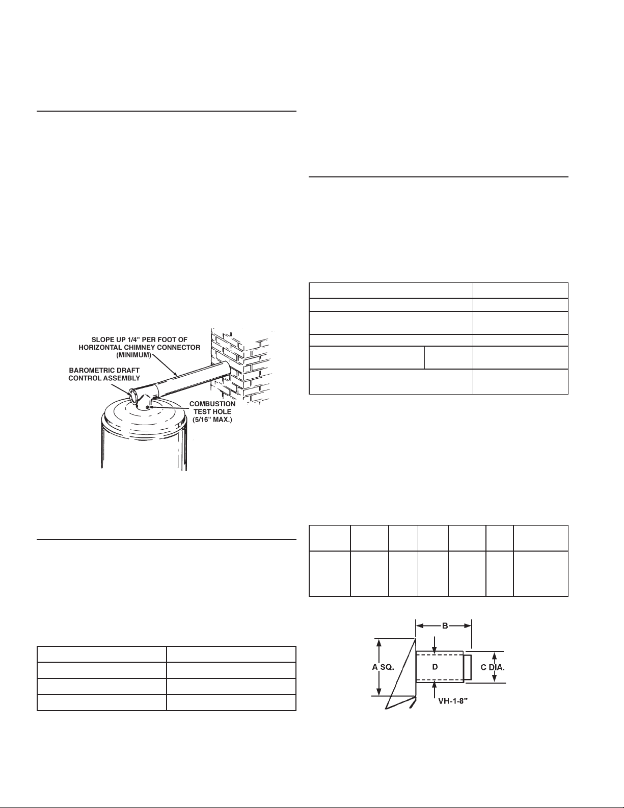
BAROMETRIC DRAFT CONTROL ASSEMBLY
A double-acting barometric draft control assembly is provided
with each unit. The draft control assembly must be installed
without alteration. This assembly is factory adjusted for horizontal
application only and must be attached to the heater as shown in
Figure 16. The outlet of the draft control assembly may be rotated
to face in direction needed. The assembly must be tted to the
jacket cover such that it is plumb and level to the ground. Fasten
the draft control assembly to the top cover using sheet metal
screws at three locations, or more, as required.
Dampers or other obstructions must not be installed between the
heater and the barometric draft control assembly.
Do not adjust settings on gate. Counterweight washers are factory
adjusted and should result in breeching pressure measurements
at the combustion test hole (Figure 16) within the range shown
in Table 3.
NOTE: A negative draft 0.02” to 0.04” w.c. must be maintained in
the vent piping. When installed, the damper gate must pivot freely
in the ring guides. This gate will automatically adjust to regulate
the chimney draft imposed on the heater.
Vent connectors making horizontal runs must have a minimum
upward slope toward the chimney or vent of 1/4 inch per foot.
Vent connector length should be kept as short as possible.
Be sure that the vent pipe does not extend beyond the inside
wall of a chimney.
In venting systems where a continuous or intermittent
back (positive) draft is found to exist, the cause must
be determined and corrected. In some cases, a special
vent cap may be required. Do not install this unit on the
positive draft side of a venting system being served by a
power exhauster.
HORIZONTAL (SIDE-WALL) VENTING FOR BTPV MODELS
An exhaust vent hood, vent hood and a flue reducer are
supplied with any unit intended for through-the-wall horizontal
venting. These parts must be installed without alteration. The
vent hood adapter is designed for use with Selkirk Metalbestos
Model PS or Model G venting. See Figure 17.
Refer to Table 6 for limitations of venting system design for
horizontal venting.
TABLE 6.
BTPV-540A-740A
Flue Outlet Dia. (Inches/mm) 9" (228.6)
Flue Reducer
Dimensions - Supplied (Inches/mm)
Minimum Outlet Vent Dia. (Inches/mm) 8" (203.2)
Maximum Number
Of Elbows
Maximum Total Vent System
Length, Equiv. Feet/Meters
90°
45°
9" x 8"
228.6 x 203.2
4
8
75
(23 m)
PROPER DRAFT CONTROLLER AND
VENT PIPE INSTALLATION
FIGURE 16.
VENT CONNECTION
Vent connections must be made to an adequate stack
or chimney. Refer to the National Fuel Gas Code (current
edition) or to the vent pipe manufacturer’s gas vent and
chimney sizing table to properly design and size the venting
system. Refer to Table 5 for the vent pipe size required for
installation to the barometric draft control assembly outlet.
TABLE 5. BAROMETRIC DRAFT CONTROL
ASSEMBLY OUTLET SIZE
Model Flue Outlet
BTP-540A 9″ (228.6 mm)
BTP-650A 9″ (228.6 mm)
BTP-740A 9″ (228.6 mm)
When calculating the equivalent length of a venting system each
90° elbow is equivalent to 10 feet (3 m) of straight pipe. In no case
45° elbow is equivalent to 5 feet (1.5 m) of straight pipe. In no
case may the sum of the straight pipe lengths and the equivalent
length of the elbows exceeds 80 feet (24.3 m).
Note the minimum vent diameter in Table 2.
Refer to Table 7. for the correct vent terminal size for each heater.
The dimensions noted in Table 7. refer to Figure 17.
TABLE 7.
Heater
Model
BTPV
540A- VH-1-8” 19-7/8” 13” 10-9/16” 8-5/8” 11-1/16”
740A
Terminal
Model
A B C D
Rough-In
Dimensions
Where an existing chimney or vent is to be used, be sure that
the chimney or vent has adequate capacity for the number
and sizes of gas appliances being vented through it. Inspect
the chimney or vent and remove all soot or other obstructions
which will retard free draft.
FIGURE 17.
Use only the sidewall vent terminal supplied with the heater.
These terminals are specifically listed for use on these
A.O. Smith heaters.
18
SIDEWALL TERMINATION INSTALLATION
1. If installing only vent (exhaust) piping in a Power Vent
conguration through a sidewall; ensure that all exterior sidewall
clearance requirements for the termination, shown in Figure
18A on page 20, are being maintained. These clearances and
those cited by local and national codes must be maintained.
2. If installing both intake air and vent piping in a Direct Vent
conguration through a sidewall; ensure that all exterior sidewall
clearance requirements for the terminations, shown in Figure
18B on page 21, for the vent and intake air termination are
being maintained. These clearances and those cited by local
and national codes must be maintained.
VENT SYSTEM INSTALLATION
This heater is a category III appliance when horizontally vented
through a wall using the supplied sidewall vent terminal. All national
and local codes pertaining to the installation of such venting
systems must be followed.
Horizontal portions of the vent system must be installed with a
minimum upward slope of 1/4” per foot of length.
All joints and seams in the venting system must be sealed gas
tight. If a silicone sealer is used, it must have a continuous
temperature rating of at least 500°F (260°C); Dow Corning
736 or equivalent must be used.
CAUTION
Use only the vent hood supplied with this kit. Only supplied hood
provides required clearances from combustibles, both through
the wall and the exterior siding. Termination of a sidewall vent
system with a device other than the supplied vent hood could
affect system performance and result in a safety hazard.
IMPORTANT
Plan the layout of the vent system backward from the vent
termination to the water heater.
1. Use the layout of the vent system backward from the vent
termination to the water heater.
BEWARE OF CONCEALED WIRING AND PIPING INSIDE
OF WALL. REFER TO TABLE 5 FOR THE MAXIMUM WALL
THICKNESS “B” FOR EACH MODEL.
2. Slide hood through opening from outside. Fasten hood to
exterior wall with anchors and screws supplied.
3. Install covers plate and fasten to inside wall with 4 screws.
4. Attach a seal ring (Meltalbestos SR or equivalent) to the
vent hood collar, see Figure 7. Attach Selkirk Metalbestos
model PS or model G venting to the seal ring following the
venting manufacturer’s instructions. For total safety, it is
recommended that only venting listed for use with category
III appliances (positive vent pressure, non-condensing)
should be used between the heater and the vent hood, even
through national or local codes may allow the use of type B
or single-wall vent.
5. Install the remaining vent sections back to the heater, following
the venting manufacturer’s instructions on assembling and
sealing joints. Follow good venting practice regarding properly
supporting vent system and keeping the number of offsets to
a minimum. See Table 2 for the maximum allowable number
of elbows in venting system.
6. Install the ue reducer included with the exhaust hood between
the vent system and the heater.
7. Seal all vent connections and venting with sealants supplied
by vent pipe manufacturer or with a high-temperature
silicone sealant suitable for continuous temperatures of
500°F (260°C). Acceptable sealant include Dow Corning 736
or equivalent.
DIRECT VENTING - FOR BTPV MODELS
All exhaust vent terminal, flue reducer, and intake vent terminal
are supplied with any unit intended for direct venting. These
parts must be installed without alteration.
This heater is category III appliance when used in a direct
vent application. All national and local codes pertaining to the
installation of such an appliance must be followed.
Horizontal portions of the exhaust vent system must be
installed with a minimum upward slope of 1/4” (6.35 mm) per
foot of length.
Selkirk metalbestos model PS or G vent is approved for use as
exhaust venting on these models. Model PS is a double -wall
vent with a 1” (25.4 mm) air space between pipes. Model G is
a single-wall variation of model PS for use where combustible
clearance is not a concern. See Table 8.
TABLE 8.
Selkirk Metalbestos Model PS
Clearance to Combustibles
Interior 6" (152.4 mm)
Exterior 6" (152.4 mm)
8” diameter PVC or galvanized pipe is approved for use as
intake venting on these models. Class 63, 100, 125, 200, and
schedule 40 pipe may be used for PVC pipe. Intake venting
must be adequately supported to avoid unnecessary stress on
vent hood, venting, or burner.
See Table 9. limitations on venting system design for direct
vent installations.
TABLE 9.
Dimension in Inches (mm) BTPV 540A-740A
Flue Outlet Dia. 9 (229)
Flue Reducer Dimension (Supplied) 9 x 8 (229 x 203)
Min. Exhaust Vent Dia. Inch (mm) 8 (203)
Min. Intake Vent Dia. Inch (mm) 8 (203)
Maximum Number Of Elbows, Intake
Maximum Number Of Elbows, Exhaust
Total Intake Vent Length, Equiv. Ft.
Total Exhaust Vent Length, Equiv. Ft.
Note: Barometric draft control is not used in direct vent installations
as the venting system must be sealed.
When calculating the equivalent length of a venting system
each 90 elbow is equivalent to 10 feet of straight pipe. Each
45 elbow is equivalent to 5 feet (1.5 m) of straight pipe. Do
not exceed the maximum number of elbows as shown in
Table 5. In no case may the sum of the straight pipe lengths and
the equivalent lengths of the elbows exceed the valves in Table 5.
90° 4
45° 8
90° 4
45° 8
Max. 75 (23 m)
Min. 3 (1 m)
Max. 75 (23 m)
Min. 6 (1.8)
19
 Loading...