

Page 1

WW
AA
TER HEATER HEA
W
A
TER HEA
WW
AA
TER HEATER HEA
BB
ULLETINULLETIN
B
ULLETIN
BB
PSD - Alsip, Illinois
Date: December 20, 1999 No. 137 Rev. 2
Subject: Gas Water Heater Conversion Policy
To: All Accounts
* This supersede all previous letters and field bulletins concerning residential and commercial water heater conversion.
ULLETINULLETIN
TERTER
TER
TERTER
GAS WATER HEATER CONVERSION POLICY
All A.O. Smith Water Products Company’s residential and commercial gas water heaters are designed certified by CSA or UL,
under ANSI Standards for operation on one type of gas only, as indicated on the water heater’s model number and rating
plate.
A.O. Smith realizes that there may be certain situations where a field conversion may be necessary and in order to facilitate
such a conversion, A. O. Smith complies with CSA or UL regulations ensuring that a field conversion be appropriately and
safely completed.
An improper field conversion from one type of gas to another could cause potentially dangerous conditions that may cause an
explosion or fire resulting in property damage, bodily injury or both.
A.O. SMITH WILL ONLY ALLOW THE CONVERSION OF GAS WATER HEATERS FROM LP GAS (PROPANE) TO
NATURAL GAS. THE CONVERSION OF A GAS WATER HEATER FROM NATURAL GAS TO LP GAS (PROPANE) IS
NOT ALLOWED UNDER ANY CIRCUMSTANCES.
A.O. Smith will provide kits as demand warrants through our Parts Department, phone no.
1-800-433-2545. Prices, dimensions and specifications are subject to change without notice.
Each conversion kit is to be installed by an A.O. Smith service agent or a gas utility serviceman in accordance with
A.O. Smith’s written instructions and all codes and requirements of the authority having jurisdiction. Failure to follow
instructions could result in serious injury or property damage. The utility performing this work assumes responsibility for
this conversion.
Changing the Input on Gas Water Heaters
The only changes to the input of a gas water heater allowed are:
• Adjustments to match that shown on the rating plate of the heater. The installation instructions supplied with the
heater indicate if adjustments to input are a required procedure.
• Changes made as required to adjust the heater for proper operation at high altitude as determined by a qualified
service technician. Service manuals include the proper procedure for adjusting heaters at high altitudes.
Conversion of Gas Water Heaters
The conversion of LP gas (Propane) to Natural gas is ONLY allowed providing:
• The conversion is done as part of a gas utility’s program where propane appliances were installed anticipating the
completion of natural gas service to the area. The conversion must be done under the direct supervision of the
utility and by their service representatives.
Claims of damage or injury arising from the unauthorized conversion of any A.O. Smith water heater not design certified for
conversion will be the complete and total responsibility of the person or entity making the conversion.
If you have any questions regarding the above policy, please contact the A.O. Smith Parts Department at 1-800-433-2545 or
our Technical Information Center at 1-800-527-1953.
A.O. SMITH WATER PRODUCTS CO., INC.
5621 W. 115TH STREET • ALSIP, ILLINOIS 60803
FAX: 1-800-433-2515 • www.hotwater.com
Printed in the U.S.A. 2574 04/00 No. 137 Rev. 2
PHONE: 1-800-433-2545
Page 2
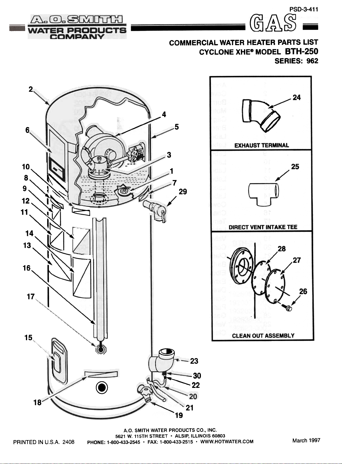
COMMERCIAL WATER HEATER PARTS LIST
CYCLONE XHEe MODEL BTH-250
SERIES: 962
2
4
6
I
10"",~
: ~
14
,
1 3 "'"
16
17
J,
~
-
'--- .
5
3
---
1
7
29
~
15
18
PRINTED IN U.S.A. 2408
~
J
~
23
~ ~~ 2 2
-30
@
21
A.O. SMITH WATER PRODUCTS CO., INC.
PHONE: 1-800-433-2545 . FAX: 1-800-433-2515 . WWW.HOTWATER.COM
5621 W. 115TH STREET. ALSIP, ILLINOIS 60803
March 1997
Page 3

CYCLONE XHECH> MODEL
BTH-250 WATER HEATER PARTS LIST
II.EM
1
2
3
4
5
6
7
8
9
10
11
12
13
14
15
16
17
18
19
20
21
22
23
24
25
26
27
28
29
30
31*
32*
DESCRIPTION
Anode
Cover, Jacket
Burner Assembly
Motor, Blower
Cage, Housing
Bracket, Control Panel
Label, Relief Valve
Label, A.O. Smith Commercial
Label, 800 Help Line
Label, Warning E.C.O.
Label, Connection Diagram
Label, Rating Specifications
Label, Lighting and Operating
Label, Warning" Clearance
Cover, Front
Channel
Temperature Probe, Lower
Label, Water Inlet
Valve, Drain
Condensate Hose
Clamp, Hose
Barb, Hose
Elbow, 90 Degree
Exhaust Vent Terminal
Direct Vent Intake Tee
Screw, Self Tapping
Plate, Pressure
Gasket
Valve, Relief
Clamp, Hose, Nylon Snap
Label, Water Outlet
Label, Cleanout
BTH-250
043817-004
192664-000
192417-002
193203-000
192420-000
192716-000
191068-000
043271-001
190600-000
192282-000
193204-000
190238-013
192888-000
192895-000
181260-000
095312-003
192609-000
094518-000
180904-001
181864-000
192806-000
181863-000
192473-000
192815-000
181762-000
069852-001
099037-000
099038-000
192467-000
191794-001
094519-000
078754-000
* Not Illustrated
Part numbers underlined are recommended stock items for emergency
replacement.
2
Page 4

CYCLONE XHEe MODEL
BTH-250 CONTROLS PARTS LIST
TO II.OW£R ~
./
-"""""
"-=
i
B--~~~
~::jJ}""~~"/,..D
.
(f4)
lIfM
1
2
3
4
5
6
7
8
9
1
0
1
1
1
2
1
3
1
4
1
5
1
6
7
1
1
8
1
9
2
0
2
1
DESCRIPTION
Transformer
Control Board
E.C.O.fTemperature Probe
Blower Proving Switch
Low Voltage Cable Assembly
Line Voltage Cable Assembly
Blower Assembly
Igniter Assembly
Cable to Control Display Board
Board, Display Panel
Blocked Outlet Proving Switch
Temperature Probe, Lower
Wire Assembly, Air Flow Switch
Tubing, Pressure
Tubing, Pressure
Tubing, Connector
Blower Speed Reducing Panel
Low Gas Pressure Switch
Blocked Inlet Switch
Wire Assembly, Air Flow Switch
Switch-On/Off
BTH-250
192608-000
192624-000
192606-000
193221-000
192605-000
192607-000
193203-000
192638-001
192623-000
192622-000
192946-000
192609-000
192802-001
192024-002
192024-006
192152-000
192987-000
193221-000
192947-000
192802-000
192699-000
3
Page 5

3
16
10
11
12
13
14
15
16
17
18
19
20
21
1
2
3
4
5
6
7
"
8
9
Burner 192416-000
Igniter Assembly 192638-000
Rivet, Blind, 1/8" Dia 316 SS 192730-000
Air Deflector 192414-000
Air Restrictor 192450-002
Barb, Hose, 3/16" 192800-000
Flame Rod Assembly 192478-000
Screw, Self Tapping #8-18 192698-000
Orifice 192477-002
Orifice Holder 192447-000
Union, Pipe 095515-000
Nipple, 3/4 Pipe 085040-018
Valve, Gas 192454-000
Motor, Blower 193203-000
Tube, Air 192469-000
Clamp, 3" 192696-000
Bracket, Blower Mounting 192482-000
Flange Assembly, Inlet 192886-000
Low Gas Pressure Switch 193222-000
(Reference: See Controls Drawing & Parts List)
Nipple, 1/8", Pipe 192948-000
Elbow, 1/8", 90° 192949-000
Part numbers underlined are recommended stock items for emergency
replacement.
4
 Loading...