

Page 1

Innovation has a name.
BFM
Balanced flue
commercial water heater
BFM – 30/50/80/100/120
Wide range of balanced fanned fl ue room-sealed water heaters
for installation in almost any location • Improved effi ciency
• Removable control column for convenient servicing • Control,
high limit and energy cut-off thermostat triple protection ensures
safe operation • Frost-protection thermostat • Stainless-steel
burner for natural or LP gas • Two access covers for comprehensive
waterside tank maintenance • Voltage-free contact for general
fault indication • Steel pallet base for convenient transport and
installation • Optional ancillaries: Unvented kits • Destratifi cation
pump kit • Powered anode
Page 2

BFM
Technical specifications
BFM 30
BFM 50
BFM 80
BFM 100
BFM 120
Gas data natural gas 2H (G20)
Input* kW 32.2 52.2 83.3 113.3 127.7
Output kW 26.4 42.3 67.5 90.8 102.4
Inlet pressure mbar 20 20 20 20 20
Burner pressure mbar 12.5 12.9 12.9 12.5 14.0
Gas consumption** m3/h 3.1 5.0 7.9 10.8 12.2
Diameter pilot orifice mm 0.56/0.41 0.56/0.41 0.56/0.41 0.56/0.41 0.56/0.41
Diameter main orifice mm 2.6 2.5 2.7 3.2 3.3
Max. flue gas temperature °C 130 150 145 180 185
Flue gas discharge kg/h 74.2 105.7 191.9 232.5 265.8
Gas data butane 3+ (G30)
Input* kW 31.4 49.9 81.3 110.5 n/a
Output kW 26.4 41.4 67.5 90.8 n/a
Inlet pressure mbar 50 50 50 50 n/a
Burner pressure mbar - - - - n/a
Gas consumption** kg/h 2.3 3.6 5.9 8.0 n/a
Diameter pilot orifice mm 0.25 0.25 0.25 0.25 n/a
Diameter main orifice mm 1.25 1.25 1.3 1.7 n/a
Max. flue gas temperature °C 130 150 145 180 n/a
Flue gas discharge kg/h - 98.6 187.8 228.7 n/a
Gas data propane 3+ (G31)
Input* kW 30.4 47.8 77.2 110.9 125.0
Output kW 25.5 39.6 63.9 90.8 102.4
Inlet pressure mbar 37 37 37 37 37
Burner pressure mbar - - - - 22
Gas consumption** kg/h 2.2 3.4 5.5 7.9 8.9
Diameter pilot orifice mm 0.25 0.25 0.25 0.25 0.25
Diameter main orifice mm 1.45 1.4 1.5 1.95 2.3
Max. flue gas temperature °C 130 150 145 180 185
Flue gas discharge kg/h 71.4 105.1 194.3 232.0 264.7
Draw-off capacity
Storage capacity l 309 298 253 253 253
Max. temperature setting °C 73 73 73 73 73
30 min. ∆T=44°C l 569 697 870 1074 1176
60 min. ∆T=44°C l 827 1111 1529 1962 2176
90 min. ∆T=44°C l 1085 1524 2189 2849 3177
120 min. ∆T=44°C l 1343 1937 2849 3736 4177
Continuous ∆T=44°C l/h 516 827 1319 1774 2000
Heating-up time ∆T=44°C min. 36 22 12 9 8
30 min. ∆T=50°C l 501 613 765 946 1035
60 min. ∆T=50°C l 728 977 1346 1726 1915
90 min. ∆T=50°C l 955 1341 1926 2507 2796
120 min. ∆T=50°C l 1182 1705 2507 3288 3676
Continuous ∆T=50°C l/h 454 728 1161 1561 1760
Heating-up time ∆T=50°C min. 41 25 13 10 9
30 min. ∆T=55°C l 455 558 696 860 941
60 min. ∆T=55°C l 662 888 1223 1569 1741
90 min. ∆T=55°C l 868 1219 1751 2279 2541
120 min. ∆T=55°C l 1074 1550 2279 2989 3342
Continuous ∆T=55°C l/h 413 661 1055 1419 1600
Heating-up time ∆T=55°C min. 45 27 14 11 9
Electrical data
Power consumption W 100 100 100 275 300
Power supply VAC/Hz 230 (-15/+10%) / 50
General
Pressure differential Pa 200/170 270/240 255/225 610/580 220/190
Diameter of air restrictor mm 36 42 54 48 64
Anodes - 2 2 4 4 4
Maximum working pressure bar 8
Maximum weight kg 539 543 548 573 573
Shipping data
Weight empty kg 230 245 295 320 320
Weight incl. packaging kg 260 275 325 350 350
Width packaging mm 800 800 800 800 800
Height packaging mm 2080 2080 2080 2080 2080
Depth packaging mm 1040 1040 1040 1040 1040
* Gas data on gross value
** Gas consumption at 15°C and 1013.25 mbar
Page 3
BFM
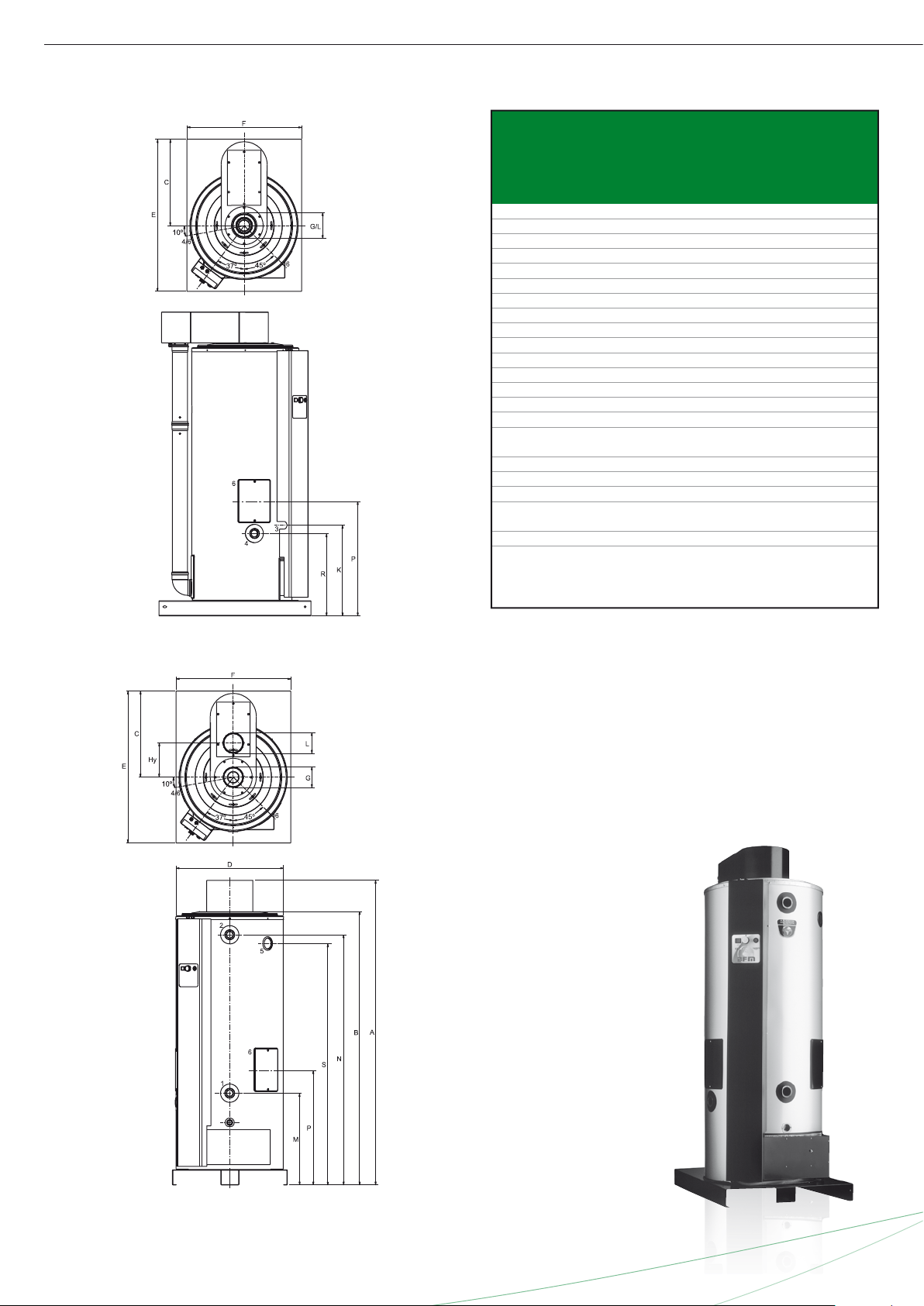
Dimensions
A 2000 2000 2020 2020 2020
B 1800 1800 1820 1820 1820
C 580 580 580 580 580
D 710 710 710 710 710
E 1000 1000 1000 1000 1000
F 755 755 755 755 755
G 125 125 150 200 130
Hy - - - 235 235
K 600 600 600 600 760
L 125 150 200 130 130
M 600 600 590 590 590
N 1640 1640 1655 1655 1655
P 770 770 760 760 760
R 550 550 540 540 540
S 1600 1600 1600 1600 1600
1 Cold water (external) R11/2
2 Hot water (internal) Rp1
1
/2
3 Gas control (internal) Rp
3
/4 (BFM120 = Rp1)
4 Tank drain valve (internal) R1
1
/2
5 T&P valve (internal) 1-11.5 NPT (BFM 30-50)
Rp1
1
/2 (BFM 80-120)
6 Cleaning and inspection opening Ø100
Dimensions in mm. All BFM water heaters receive a three years
warranty on the tank and one year on parts.
BFM 30
BFM 50
BFM 80
BFM 100
BFM 120
BFM 30-80
BFM 100-120
Page 4
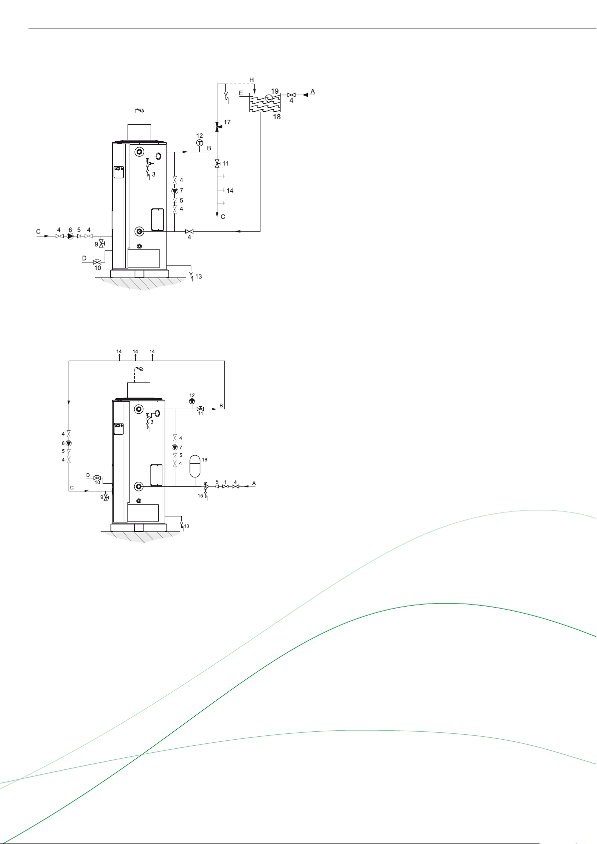
1 Pressure reducing valve
3 T&P valve
4 Stop valve
5 Non-return valve
6 Circulation pump
7 Destratifi cation pump
9 Drain valve
10 Gas cock
11 Isolating valve
12 Temperature gauge
13 Condense drain
14 Hot water outlets
15 Expansion relief valve
16 Expansion vessel
17 Three way valve
18 Water tank
19 Float valve
A Cold water
B Hot water
C Return circulation
D Gas supply
E Overfl ow pipe
H Expansion vent pipe
A.O. Smith unvented system kits utilise combination valves.
Further installation and connection details can be found in
the Installation & Commissioning Manual.
BFM
Installation diagrams
Vented
Unvented
Page 5

BFM
Electrical diagram
A = Jacket
B = Isolating transformer
C = APDS (Air pressure
differential switch)
C = Filter
E = Reset button
F = Frost thermostat
G = Control thermostat
H = ON/ OFF switch
K = Safety thermostat
L = High-limit thermostat
M = Burner control
N = Connector clip strip
P = Earthing strip
R = Clock (optional)
S = Relay
T = Potentiostat (optional)
Page 6

X
Y
V
W
W
Y
V
X
X1
Y1
V
W
X2
Y2
V
W
W
Y
V
X
Flue systems BFM
Installation options
C13 C13
C33 C33
Flue systems BFM
A BFM water heater should be installed according category
C13 or C33.
BFM 30
BFM 50
BFM 80
BFM 100
Concentric x x x - -
Parallel - - - x x
Diameter (mm) 80/125 100/150 130/200 2 x 130 2 x 130
Max. length (m) 7 7 7 7 7
Max. 45/90° bends a pipe 2 2 2 2 2
BFM 120
Concentric flues
It is not permitted to use more than the specified number of
bends, even when the duct is shorter than the maximum length.
A 45° bend is equivalent to a 90° bend.
Parallel flues
The parallel flue of a BFM 100 of 120 unit should always be
connected to the wall or roof penetration using the standard
transition piece (0306801). The two ducts shall not terminate
in different pressure zones.
Note: horizontal flue runs must be installed with a fall of at least
5 mm per metre.
Minimum space requirements
BFM 30-80
BFM 100-120
BFM 30
BFM 50
BFM 80
Minimal space for wall duct (mm)
Ø80/125 Ø100/150 Ø130/200 2 x Ø130 2 x Ø130
V 550 550 640
W 725 790 940
X 2115 2165 2190
Y 1195 1215 1310
Y * 745 765 860
V 700 700
W 1000 1000
X1 2480 2480
Y1 955 955
X2 2140 2140
Y2 1320 1320
Y2 * 870 870
Minimal space for roof duct (mm)
V 1230 1310 1610
W 605 645 1000
X 3575 3615 3580
Y 1575 1615 1560
Y ** 625 665 610
V 2560 2560
W 1000 1000
X 3580 3580
X ** 2630 2630
Y 1560 1560
Y ** 610 610
BFM 100
BFM 120
For the parts numbers of components and flue gas ducts, etc.
please refer to the “Maintenance and accessories” chapter.
* Distance without concentric pipe between bend and wall duct.
** Distance without concentric pipe between appliance and roof duct.
Data subject to change INT/1108/BFM/02
Terms and conditions apply, please refer to our website.
www.aosmithinternational.com
 Loading...