

A.O. Smith ATI-240H-N, ATI-240H-P, ATI-340H-N, ATI-340H-P, ATI-540H-N Technical Documents
...Page 1
Residential/Commercial Gas
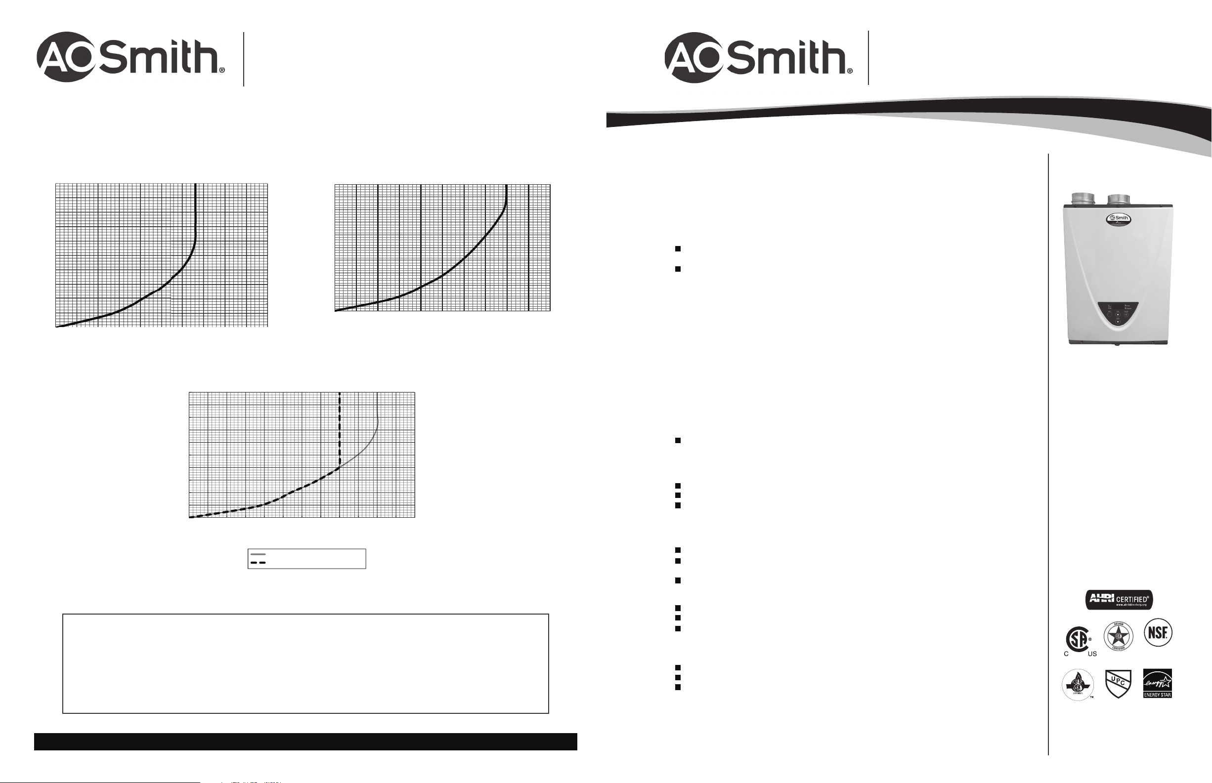
Pressure Loss (psi)
Pressure Loss (psi)
Set temperature 130˚F (55˚C) or higher
S
Tankless Water Heaters
Residential/Commercial Gas
Tankless Water Heaters
PRESSURE LOSS
TANKLESS HIGH EFFICIENCY
240H
50
45
40
35
30
25
20
15
10
5
0
0.0 1.0 2.0 3.0 4.0 5.0 6.0 7.0 8.0 9.0 10.0
Pressure Loss
Flow Rate (GPM)
120
100
80
60
40
20
0
50
45
40
35
30
25
Head (Feet)
20
15
10
5
0
0.0 1.0 2.0 3.0 4.0 5.0 6.0 7.0 8.0 9.0 10.0
540H
50
45
40
35
30
25
20
Pressure Loss (psi)
15
10
5
0
0.0 1.0 2.0 3.0 4.0 5.0 6.0 7.0 8.0 9.0 10.0 11.0 12.0
Water heater(s) shall beModel_________________ as manufactured byA.O.Smith WaterHeaters, shall bea coppercoil integral fin and tubeconstruction with quick releasebrass or bronze waterways. Heater(s)
will be factory assembled and tested.
The heater shall be vented with 3” or 4” ULC s636 approved PVC or CPVC or polypropylene vent pipe, or stainless steel Category III vent pipe at a distance not to exceed 70’ (equivalent) for 3” vent or 100’
(equivalent) for 4”vent, terminating vertically or horizontally as prescribed. Intake air pipe may be of such material as PVC or CPVC, galvanized B-Vent, corrugated aluminum or stainless steel, or Category IV
stainless steel not to exceed 70’ (equivalent) for 3” vent or 100’ (equivalent) for 4” vent.
The heater(s) shall be controlled by an onboard solid-state printed circuit board monitoring incoming and outgoing temperatures with factory installed thermistors, sensing and controlling flow rate to set point
temperature, controlling both air and gas mixture inputs to maintain thermal combustion efficiency. The heater(s) shall also consist of inline fusing, a spark ignition and sensor system, aluminized stainless steel
burners, an air-fuel ratio sensor, a hi-limit temperature switch, modulating and proportional gas valves, a freeze protection sensor with ceramic heating blocks, and an overheat cutoff fuse.
The water heater(s) shall be CSA listed, exceed the energy efficiency requirements of ASHRAE 90.1b-1992, and shall comply with SCAQMD Rule 1146.2 Ultra-Low NOx Standards.
For Technical Information call A. O. Smith Corporation reserves the right to make product changes or improvements without prior notice.
1-888-479-8324.
Pressure Loss
Flow Rate (GPM)
Flow rate (GPM)
Set temperature 125˚F (52˚C) or lower
Specification
340H
Pressure Loss
Flow Rate (GPM)
120
100
80
60
Head (Feet)
40
20
0
120
100
80
60
40
20
0
CONDENSING MODELS
FEATURES
CONDENSING TECHNOLOGY PROVIDES UNPRECEDENTED
0.95 ENERGY FACTOR
DURABLE HEAT EXCHANGERS
Primary Heat Exchanger is constructed of HRS35 Commercial-Grade Copper which is more
Head (Feet)
resilient against erosion
Secondary Heat Exchanger is made of Type 316L Stainless Steel to protect against corrosion
CONTINUOUS MAXIMUM FLOW RATES UP TO 10.0 GPM
®
ENERGY STAR
QUALIFIED
AVAILABLE IN NATURAL GAS OR PROPANE (LP)
ATI 540H CAN BE US
ED IN BOTH RESIDENTIAL AND
COMMERCIAL APPLICATIONS
ELECTRONIC IGNITION - NO PILOT LIGHT
INCLUDES A BUILT-IN TEMPERATURE CONTROLLER AND
ADVANCED DIAGNOSTICS FOR EASY TROUBLESHOOTING
FACTORY-INSTALLED POWER CORD
EASY-LINK UP TO 4 UNITS (540H MODELS ONLY)
With no additional parts or accessories needed using built-in Easy-Link System
MULTI-LINK UP TO 20 UNITS (540H MODELS ONLY) WITH A TM-MC02
SAFETY FEATURES:
Air-Fuel Ratio (AFR) Sensor
Exhaust & Water Temperature Safety Control
Overheat Cut-Off Fuse
INTERNAL FREEZE PROTECTION SYSTEM
POWER DIRECT VENT DESIG
Exhaust, 3" PVC Venting up to 70 Feet or 4" PVC Venting up to 100 Feet
Provides flexible venting with ULC s636 approved PVC or CPVC or polypropylene for Intake
and Exhaust (solid core only).
Category III Stainless Steel venting can also be used
N
ACCESSORIES
Pipe Cover
Neutralizer Kit
Isolation Valve Kits (includes Pressure Relief Valve)
Concentric Termination
WARRANTY
15-year limited warranty on heat exchanger in residential applications
-year limited warranty on heat exchanger in commercial applications
10
5-year limited warranty on all parts
ATI-240H
ATI-340H
ATI-540H
540 model
only
®
ANSI Z21.10.3 CSA 4.3
May 2013
www.hotwatercanada.ca CANRG46835
Page 4 of 4
May 2013
www.hotwatercanada.ca
Page 1 of 4
CANRG46835
Page 2
Residential/Commercial Gas
Residential/Commercial Gas
Tankless Water Heaters
INDOOR MODEL
Residential/Commercial Gas
Tankless Water Heaters
Residential/Commercial Gas
Tankless Water Heaters
Flow Rate (GPM)
11.0
Flow Rate (GPM)
11.0
Flow Rate (GPM)
Tankless Water Heaters
TANKLESS HIGH EFFICIENCY CONDENSING MODELS
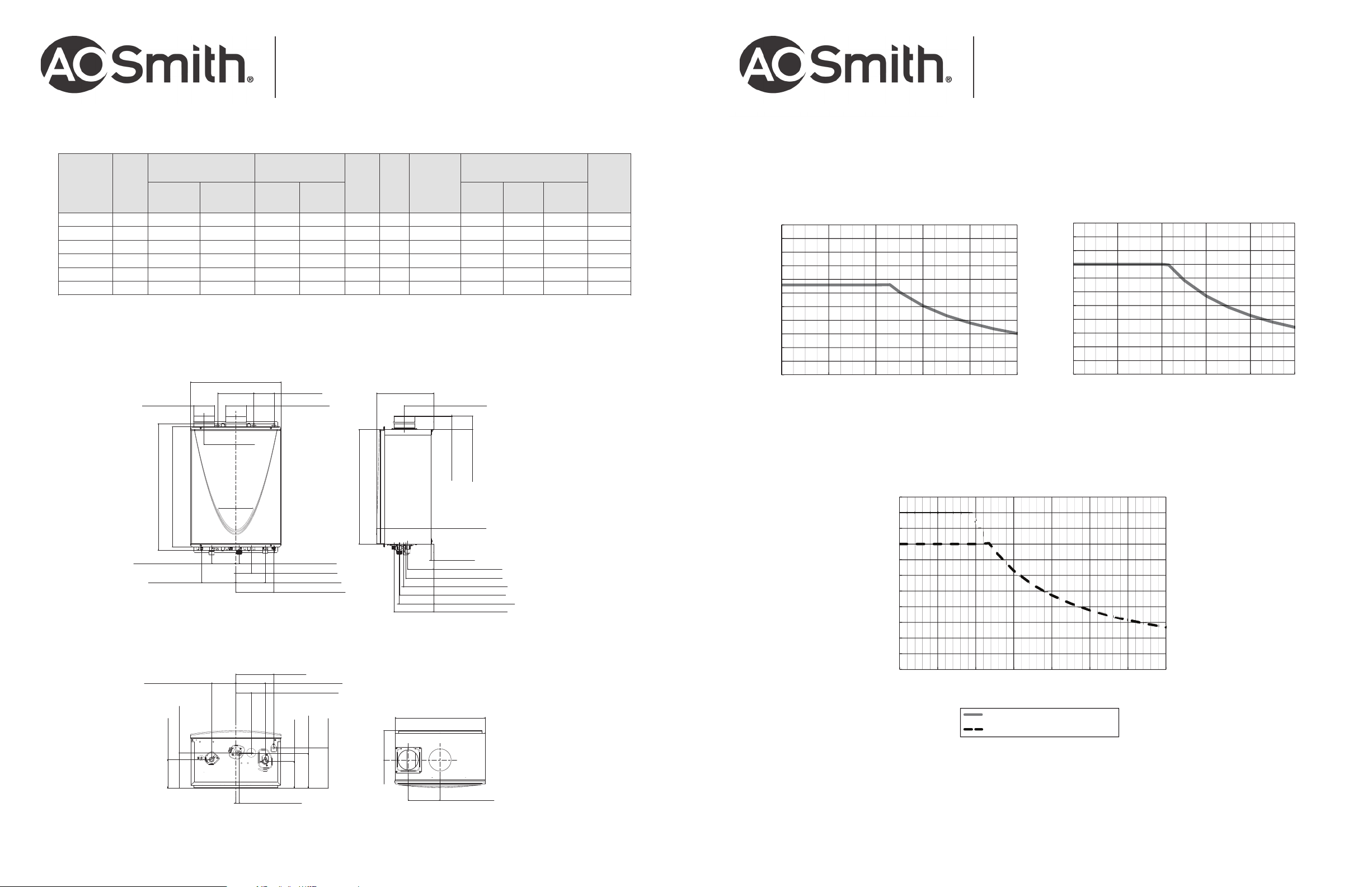
GAS CONSUMPTION
INPUT
MODEL
NUMBER
FUEL
TYPE
MINIMUM
BTU/H
MAXIMUM
BTU/H
ATI-240H-N Natural 15,000 160,000 5.0 10.5 0.95 6.6 3/4” NPT 22-1/2 17-3/4 10-3/4 58
ATI-240H-P Propane 13,000 160,000 8.0 14.0 0.95 6.6 3/4” NPT 22-1/2 17-3/4 10-3/4 58
ATI-340H-N Natural 15,000 180,000 5.0 10.5 0.95 8.0 3/4"NPT 22-1/2 17-3/4 10-3/4 58
ATI-340H-P Propane 13,000 180,000 8.0 14.0 0.95 8.0 3/4"NPT 22-1/2 17-3/4 10-3/4 58
ATI-540H-N Natural 15,000 199,000 5.0 10.5 0.95 10.0 3/4"NPT 22-1/2 17-3/4 10-3/4 59
ATI-540H-P Propane 13,000 199,000 8.0 14.0 0
All dimensions are in inches.
15-150 psi Water Pressure. 40 psi or above is recommended for maximum flow.
*Current numbers based on factory testing; 0.4 GPM required for continuous fire after initial ignition.
Models are certified from sea level to 10,100 ft. elevations.
The manufacturer reserves the right to discontinue, or change at any time, specifications or designs without notice and without incurring obligation.
17-3/4" (450 mm)
7" (180 mm)
4" (102 mm)
Female
INLET GAS
PRESSURE
MINIMUM
W.C.
4" (101 mm)
Female
MAXIMUM
W.C.
4" (102 mm)
HOT/COLD
DIMENSIONS IN INCHES
ENERGY
FACTOR
MAX
GPM*
AND
GAS CONN.
A
HEIGHTBWIDTHCDEPTH
.95 10.0 3/4"NPT 22-1/2 17-3/4 10-3/4 59
11-1/4" (285 mm)
5-3/4" (147 mm)
UNIT
WEIGHT
(LBS)
FLOW RATE vs TEMPERATURE RISE
240H
Flow Rate vs. Temperature Rise Flow Rate vs. Temperature Rise
10.0
9.0
8.0
7.0
6.0
5.0
4.0
3.0
2.0
1.0
0.0
0 20 40 60 80 100
Temperature Rise (°F)
340H
10.0
9.0
8.0
7.0
6.0
5.0
4.0
3.0
2.0
1.0
0.0
0 20 40 60 80 100
Temperature Rise (°F)
24-7/8" (631 mm)
23-5/8" (600 mm)
HOT 4-3/4" (120 mm)
Drain port
6-3/4" (170 mm)
HOT 4-3/4" (120 mm)
6-1/4" (159mm)
Condensate drain port
7-1/2" (189 mm)
COLD 5/8" (17 mm)
120 VAC 3" (77 mm)
GAS 5-3/4" (147 mm)
Condensate drain port
7-1/2" (189 mm)
GAS 5-7/8" (147 mm)
120 VAC 3" (77 mm)
540H
Intake
2-5/8" (68 mm)
2-5/8" (65 mm)
Exhaust
11.0
22-1/2" (570 mm)
10-3/4" (272mm)
1/2 (13 mm)
GAS 5-1/8" (131 mm)
HOT 5-1/2" (140 mm)
Drain port 6" (152 mm)
COLD 6-3/4" (172 mm)
120 VAC 6-7/8" (174 mm)
Condensate drain port
7-7/8" (199 mm)
17-5/8" (448 mm)
10.0
9.0
8.0
7.0
6.0
5.0
4.0
3.0
2.0
1.0
0.0
0 20 40 60 80 100 120 140
Flow Rate vs. Temperature Rise
Temperature Rise (°F)
Temperature Rise (˚F)
Set temperature 125˚F (52˚C) or lower
Set temperature 130˚F (55˚C) or
higher
120 VAC 6-7/8" (174 mm)
HOT 5-1/2" (140 mm)
COLD 5/8" (17 mm)
GAS 5-1/8" (131 mm)
7-7/8" (199 mm)
Condensate drain port
COLD 6-3/4" (172 mm)
5-3/4" (147 mm)
6-1/4" (159 mm)
 Loading...