

A.O. Smith ARGSS02708 User Manual
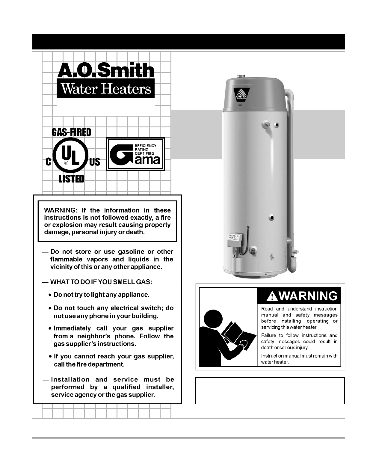
RESIDENTIAL GAS WATER HEATERS
Ashland City, TN 37015
www.hotwater.com
Instruction Manual
POWER VENTED GAS MODELS W/HOT SURFACE IGNITION
NOT FOR USE IN MANUFACTURED (MOBILE) HOMES
• For Your Safety •
AN ODORANT IS ADDED TO THE GAS USED
BY THIS WATER HEATER.
ALL TECHNICAL AND WARRANTY QUESTIONS: SHOULD BE DIRECTED TO THE LOCAL DEALER FROM WHOM THE WATER HEATER WAS
PURCHASED. IF YOU ARE UNSUCCESSFUL, PLEASE WRITE TO THE COMPANY LISTED ON THE RATING PLATE ON THE WATER HEATER.
KEEP THIS MANUAL IN THE POCKET ON HEATER FOR FUTURE REFERENCE
WHENEVER MAINTENANCE ADJUSTMENT OR SERVICE IS REQUIRED.
PRINTED 1207 197423-002
1
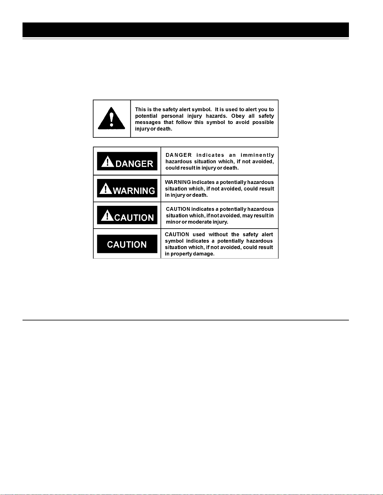
SAFE INSTALLATION, USE AND SERVICE
Your safety and the safety of others is extremely important in the installation, use and servicing of this water heater.
Many safety-related messages and instructions have been provided in this manual and on your own water heater to warn you and
others of a potential injury hazard. Read and obey all safety messages and instructions throughout this manual. It is very
important that the meaning of each safety message is understood by you and others who install, use or service this water heater .
All safety messages will generally tell you about the type of hazard, what can happen if you do not follow the safety message and
how to avoid the risk of injury.
IMPORT ANT DEFINITIONS
• Qualified Installer: A qualified installer must have ability equivalent to a licensed tradesman in the fields of plumbing,
air supply , venting and gas supply, including a thorough understanding of the requirements of the National Fuel Gas
Code as it relates to the installation of gas fired water heaters. The qualified installer must also be familiar with the
design features of water heaters, and have a thorough understanding of this instruction manual.
• Service Agency: A service agency also must have ability equivalent to a licensed tradesman in the fields of plumbing,
air supply , venting and gas supply, including a thorough understanding of the requirements of the National Fuel Gas
Code as it relates to the installation of gas fired water heaters. The service agency must also have a thorough
understanding of this instruction manual, and be able to perform repairs strictly in accordance with the service guidelines
provided by the manufacturer .
• Gas Supplier: The Natural Gas or Propane Utility or service who supplies gas for utilization by the gas burning
appliances within this application. The gas supplier typically has responsibility for the inspection and code approval of
gas piping up to and including the Natural Gas meter or Propane storage tank of a building. Many gas suppliers also
offer service and inspection of appliances within the building.
2
GENERAL SAFETY
3
GENERAL SAFETY
4

TABLE OF CONTENTS
SAFE INSTALLATION, USE AND SERVICE ...........................2
GENERAL SAFETY ............................................................. 3-4
TABLE OF CONTENTS...........................................................5
INTRODUCTION .....................................................................5
Preparing for the Installation ............................................5
TYPICAL INST ALLATION .................................................... 6-8
LOCATING THE NEW WATER HEATER ........................... 9-11
Facts to Consider About Location .............................. 9-10
Insulation Blankets .........................................................10
Combustion Air and Ventilation for Appliances
Located in Unconfined Spaces.......................................10
Combustion Air and Ventilation for Appliances
Located in Confined Spaces .....................................10-11
INST ALLING THE WATER HEATER ............................... 12-24
Chemical V apor Corrosion .............................................12
Water Piping............................................................. 12-13
Temperature-Pressure Relief Valve ...............................13
Gas Piping......................................................................14
Sediment Traps ..............................................................15
Filling the Water Heater .................................................15
Vent Pipe Assembly .......................................................15
Venting ...........................................................................15
Vent Pipe Termination ....................................................16
Planning the Vent System ..............................................17
Condensate .............................................................. 17-18
Blower Assembly Installation..........................................18
Installation of Vent System ....................................... 18-20
Vent Attenuation Assembly Installation Instructions .......21-22
Vent Pipe Preparation .............................................. 23-24
LIGHTING & OPERA TING LABEL ........................................25
TEMPERATURE REGULATION ............................................26
FOR YOUR INFORMA TION ..................................................27
Start Up Conditions
Smoke/Odor ...........................................................27
Thermal Expansion.................................................27
Strange Sounds......................................................27
Operational Conditions...................................................27
Smelly Water ..........................................................27
“Air” in Hot Water Faucets......................................27
High Temperature Shut Off System ........................27
PERIODIC MAINTENANCE ............................................ 28-30
Venting System Inspection.............................................28
Burner Operation and Inspection ...................................28
Burner Cleaning .............................................................28
Housekeeping .......................................................... 28-29
Anode Rod Inspection ....................................................29
Temperature-Pressure Relief Valve Operation ..............29
Draining ..........................................................................29
Service ...........................................................................30
LEAKAGE CHECKPOINTS ................................................... 30
REP AIR PARTS .....................................................................31
TROUBLESHOOTING ..................................................... 32-34
WARRANTY ..........................................................................35
INTRODUCTION
Thank Yo u for purchasing this water heater. Properly installed and
maintained, it should give you years of trouble free service.
Abbreviations Found In This Instruction Manual:
• CSA - Canadian Standards Association
• ANSI - American National Standards Institute
• NFPA - National Fire Protection Association
• ASME - American Society of Mechanical Engineers
• GAMA - Gas Appliance Manufacturer’s Association
• UL - Underwriters Laboratories Inc.
This gas-fired water heater is design certified by Underwriters
Laboratories Inc. under American National Standard/CSA Standard
for Gas Water Heaters ANSI Z21.10.3 • CSA 4.3 (current edition).
PREP ARING FOR THE INST ALLATION
1. Read the “General Safety” section, page 3 and 4 of this manual
first and then the entire manual carefully . If you don’t follow the safety
rules, the water heater will not operate properly. It could cause
DEATH, SERIOUS BODILY INJURY AND/OR PROPERTY DAMAGE.
This manual contains instructions for the installation, operation, and
maintenance of the gas-fired water heater. It also contains warnings
throughout the manual that you must read and be aware of. All
warnings and all instructions are essential to the proper operation of
the water heater and your safety. Since we cannot put everything
on the first few pages, READ THE ENTIRE MANUAL BEFORE
ATTEMPTING TO INST ALL OR OPERATE THE W A TER HEATER.
2. The installation must conform with these instructions and the
local code authority having jurisdiction. In the absence of local
codes, installations shall comply with the National Fuel Gas Code
(ANSI Z223.1/NFPA 54) or the Natural Gas and Propane
Installation Code (CAN/CSA B149.1) and the National Electrical
Code (NFPA 70), or the Canadian Electrical Code (C22.1). These
publications are available from The National Fire Protection
Association, 1 Batterymarch Park, Quincy, MA 02269.
3. The water heater when installed must be grounded in accordance
with the local codes, or in the absence of local codes: the National
Electrical Code (NFPA 70) or the Canadian Electrical Code (C22.1).
4. If after reading this manual you have any questions or do not
understand any portion of the instructions, call the local gas utility
or the manufacturer whose name appears on the rating plate.
5. Carefully plan the place where you are going to put the water
heater. Correct combustion, vent action, and vent pipe installation
are very important in preventing death from possible carbon
monoxide poisoning and fires, see Figures 1 and 2.
Examine the location to ensure the water heater complies with
the “Locating the New Water Heater” section in this manual.
6. For California installation this water heater must be braced,
anchored, or strapped to avoid falling or moving during an
earthquake. See instructions for correct installation procedures.
Instructions may be obtained from California Office of the State
Architect, 400 P Street, Sacramento, CA 95814.
7. Massachusetts Code requires this water heater to be installed in
accordance with Massachusetts 248-CMR 2.00: St ate Plumbing
Code and 248-CMR 5.00.
8. Complies with SCAQMD rule #1146 and districts having equivalent
NOx requirements.
5
TYPICAL INSTALLATION
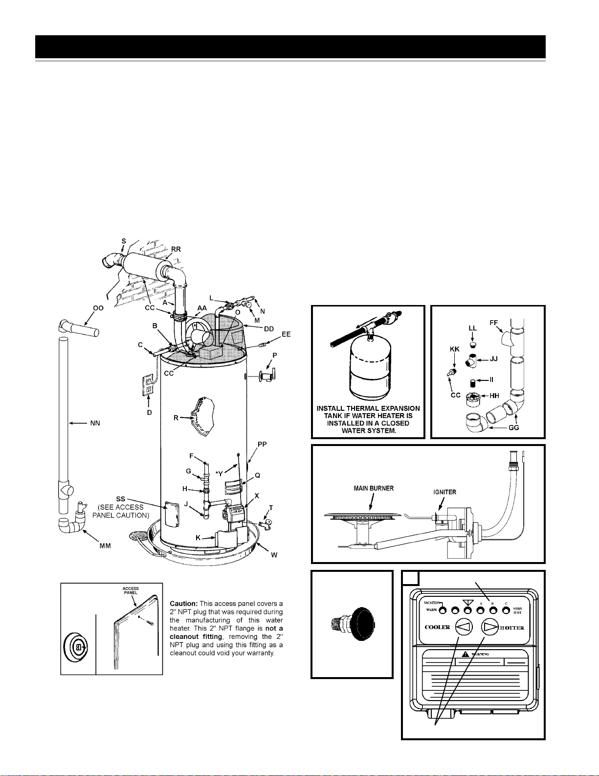
GET TO KNOW YOUR WATER HEATER - GAS MODELS
A Vent Pipe
B Anode
C Hot Water Outlet
D Outlet (120 VAC)
F Gas Supply
G Main Manual Gas Shut Off Valve
H Ground Joint Union
J Dirt Leg
K Outer Door
L Union
M Inlet Water Shut Off Valve
N Cold Water Inlet
O Inlet Dip Tube
P Temperature & Pressure
Relief Valve
Q Rating Plate
R Insulation
S Vent Terminal
T Drain Valve
U Igniter And Main Burner
W Drain Pan
X Control
Y Control Harness*
AA Motor & Blower
CC Condensate Fitting
(4 Places Shown)**
D D Plastic Top
E E On/Off Switch
FF Exhaust Tee
GG Elbow
REPLACEMENT PARTS AND DELIMING
PRODUCTS
Replacement parts and recommended delimer may be ordered through
authorized servicers or distributors. When ordering parts, provide complete
model and serial numbers (see rating plate), quantity and name of part
desired. Standard hardware items may be purchased locally.
HH Bushing
II Nipple
JJ Condensate Tee
KK Hose Barb
LL Plug
MM Vent Pipe Assembly #1
NN Vent Pipe Assembly #2
OO Vent Pipe Assembly #3
PP Side Recirculation Loop
Inlet***
QQ Side Recirculation Loop
Outlet*** (not shown)
RR Vent Attenuation
Assembly (VAA) (Optional)
SS Access Door
CONDENSATE ASSEMBLY
(U) NATURAL GAS MAIN BURNER
WITH IGNITER ASSEMBLY
VACUUM RELIEF
VALVE
*INSTAL L P ER
LOCAL CODES
* CAUTION HARNESS HAS 120 VAC. IN OPERATION.
** See "PLANNING THE VENT SYSTEM", "CONDENSATE" and "BLOWER ASSEMBLY INSTALLATION" for
more information.
***The side recirculation loop connections may not be used as the primary water inlet and outlet connections.
For your convenience, plugs are installed in these fittings at the factory . Remove these plugs if needed for
your specific installation. Otherwise (as with all connections) check for leaks while filling the tank with
water and after completing the installation.
FIGURE 1
6
SIDE VIEW
TEMPERATURE INDICATORS
(X)
TEMPERATURE ADJUSTMENT BUTTONS
TYPICAL INSTALLATION
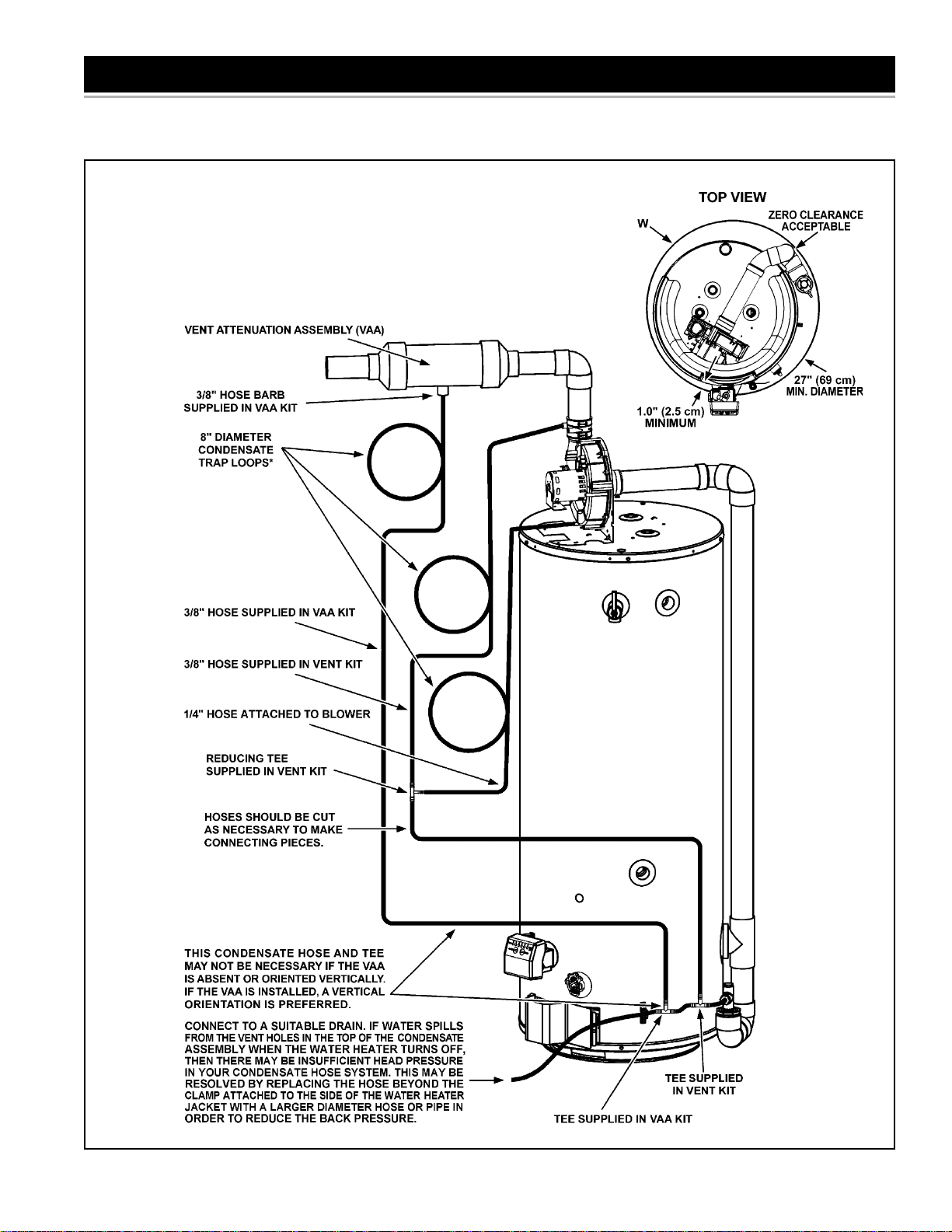
CONDENSA TE HOSE AND DRAIN PAN
*Note: Condensate Trap Loops must be oriented in a vertical plane as shown. The traps
also must be primed by filling half of the loop with water prior to operating the water heater.
Carefully plan the location of the loops and straight sections of hose prior to cutting hoses.
If necessary, secure the hoses to the side of the water heater or some other rigid structure
to prevent crimping. While securing the hoses, do not pierce or crimp the hoses.
FIGURE 1 (continued).
7
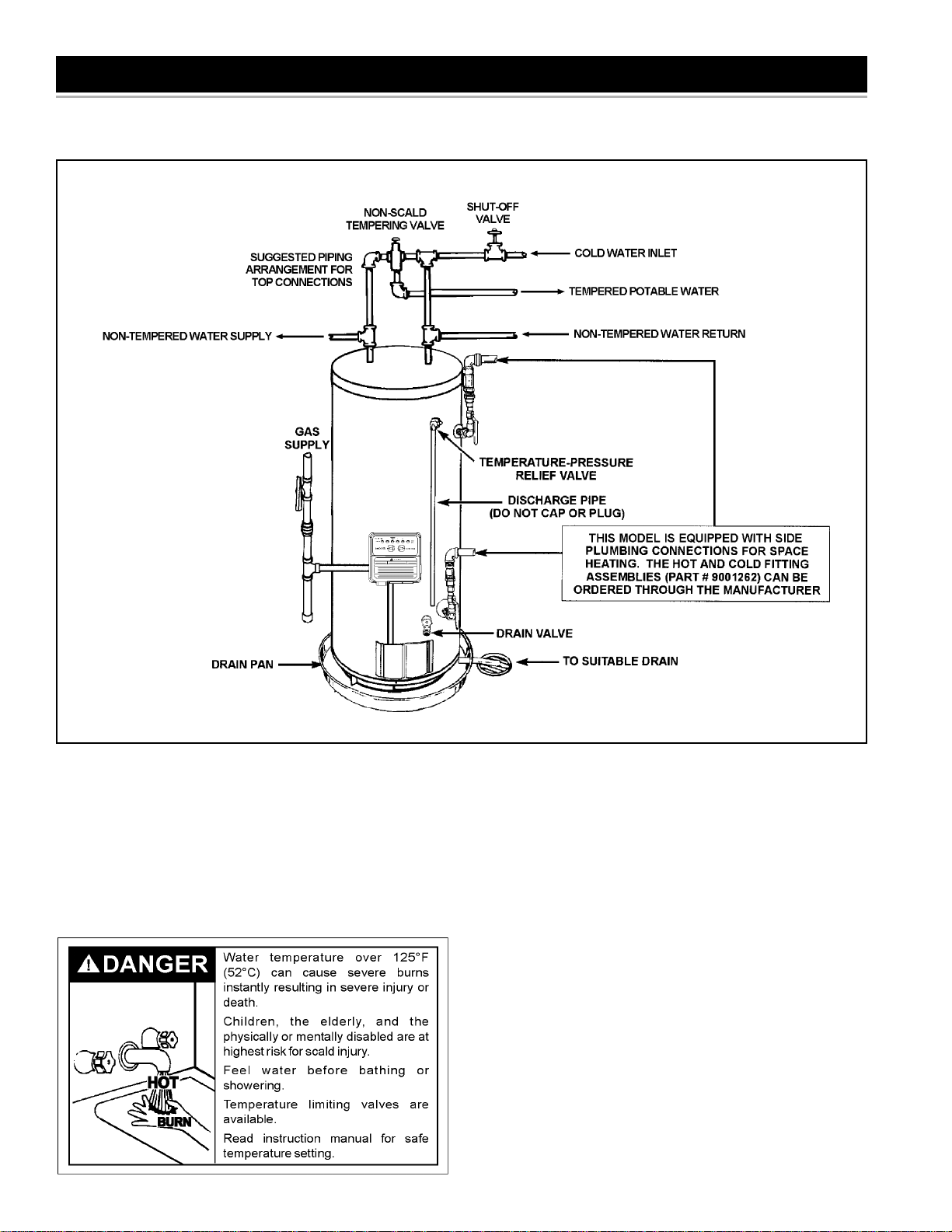
TYPICAL INSTALLATION
MIXING VAL VE USAGE
FIGURE 2.
This appliance has been design certified as complying with American
National Standard/CSA S tandard for water heaters and is considered
suitable for:
Water (Potable) Heating and Space Heating: All models are
considered suitable for water (potable) heating and space heating.
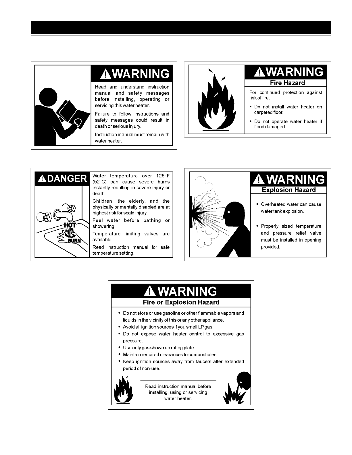
HOTTER WATER CAN SCALD:
Water heaters are intended to produce hot water. W ater heated to a
temperature which will satisfy space heating, clothes washing, dish
washing, and other sanitizing needs can scald and permanently injure
you upon contact. Some people are more likely to be permanently
injured by hot water than others. These include the elderly , children,
the infirm, or physically/mentally handicapped. If anyone using hot
water in your home fits into one of these groups or if there is a local
code or state law requiring a certain temperature water at the hot
water tap, then you must take special precautions. In addition to
using the lowest possible temperature setting that satisfies your hot
water needs, a means such as a Mixing Valve, shall be used at the hot
water taps used by these people or at the water heater. Mixing valves
are available at plumbing supply or hardware stores. Consult a Qualified
Installer or Service Agency. Follow mixing valve manufacturer ’s
instructions for installation of the valves. Before changing the factory
setting on the thermostat, read the “T emperature Regulation” section in
this manual, see Figure 26.
8
LOCATING THE NEW WATER HEATER
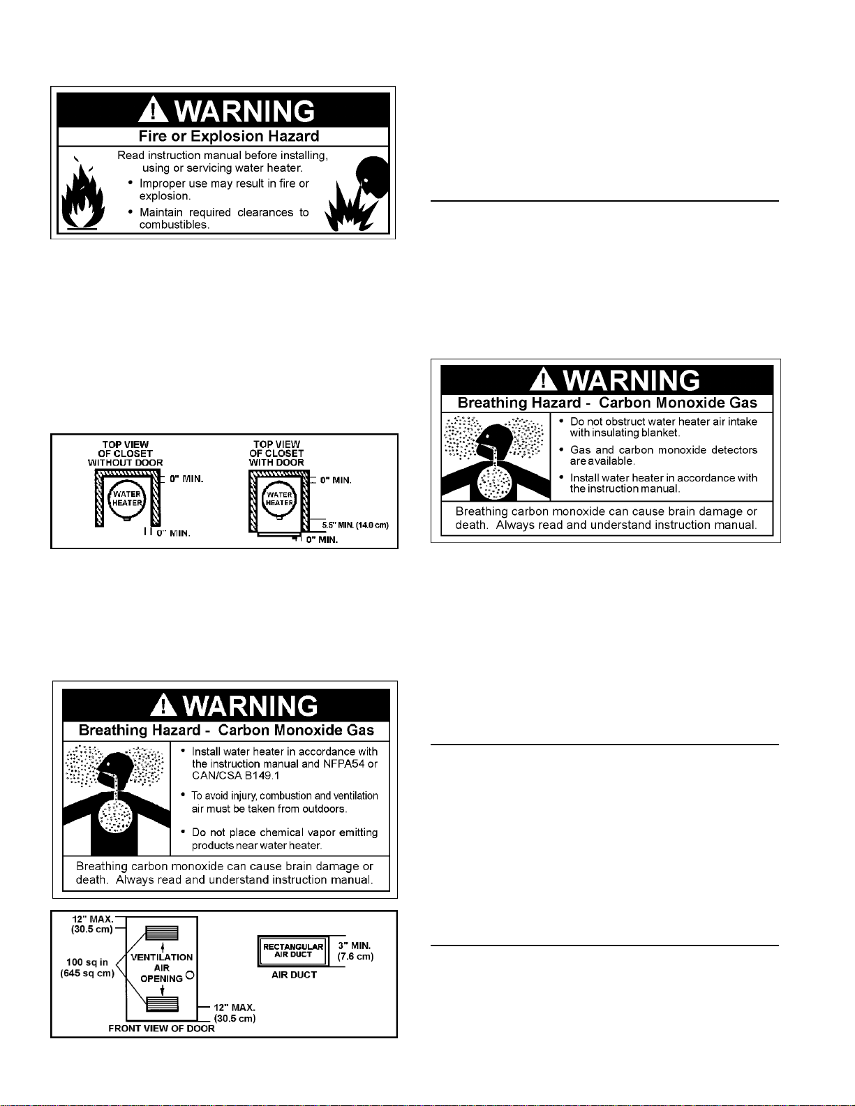
FACTS TO CONSIDER ABOUT THE LOCA TION
Carefully choose an indoor location for the new water heater, because
the placement is a very important consideration for the safety of the
occupants in the building and for the most economical use of the
appliance. This water heater is not for use in manufactured
(mobile) homes or outdoor installation.
Whether replacing an old water heater or putting the water heater in a
new location, the following critical points must be observed:
1. Select a location indoors as close as practical to the vent terminal or
location to which the water heater vent piping is going to be connected,
and as centralized with the water piping system as possible.
2. Selected location must provide adequate clearances for servicing
and proper operation of the water heater.
Installation of the water heater must be accomplished in such a manner
that if the tank or any connections should leak, the flow will not cause
damage to the structure. For this reason, it is not advisable to install
the water heater in an attic or upper floor. When such locations cannot
be avoided, a suitable drain pan should be installed under the water
heater. Drain pans are available at your local hardware store. Such
a drain pan must have a clearance of at least 1.0" (2.5cm) greater
than any point on the water heater’s outer jacket and must be piped
to an adequate drain. The pan must not restrict combustion air flow .
For example, if a circular pan is used, it must be a minimum of 27"
(69cm) in diameter. See Figure 1.
Water heater life depends upon water quality, water pressure
and the environment in which the water heater is installed. Water
heaters are sometimes installed in locations where leakage may
result in property damage, even with the use of a drain pan piped
to a drain. However, unanticipated damage can be reduced or
prevented by a leak detector or water shut-off device used in
conjunction with a piped drain pan. These devices are available
from some plumbing supply wholesalers and retailers, and detect
and react to leakage in various ways:
• Sensors mounted in the drain pan that trigger an alarm or turn off
the incoming water to the water heater when leakage is detected.
• Sensors mounted in the drain pan that turn off the water supply
to the entire home when water is detected in the drain pan.
• Water supply shut-off devices that activate based on the water
pressure differential between the cold water and hot water pipes
connected to the water heater.
• Devices that will turn off the gas supply to a gas water heater
while at the same time shutting off its water supply.
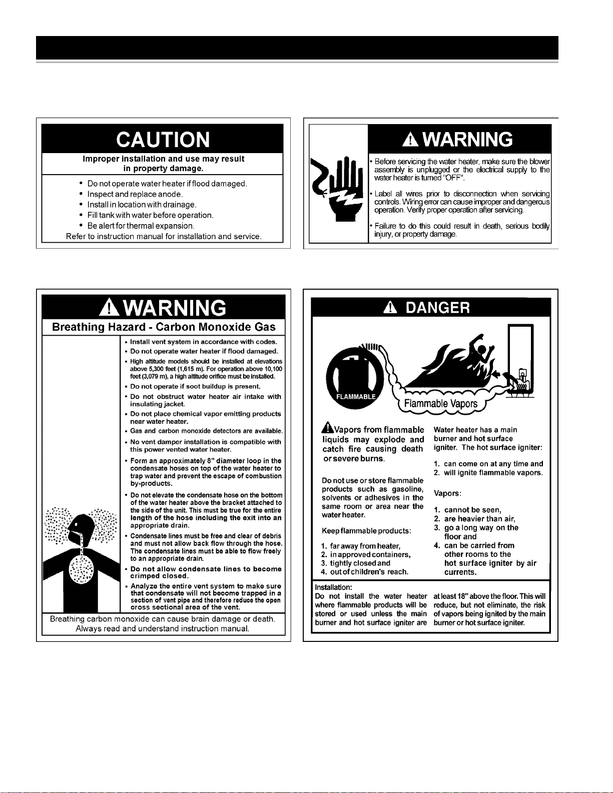
INSTALLATIONS IN AREAS WHERE FLAMMABLE LIQUIDS
(VAPORS) ARE LIKELY TO BE PRESENT OR STORED
(GARAGES, STORAGE AND UTILITY AREAS, ETC.): Flammable
liquids (such as gasoline, solvents, propane (LP or butane, etc.)
and other substances (such as adhesives, etc.) emit flammable
vapors which can be ignited by a gas water heater’s hot surface
igniter or main burner. The resulting flashback and fire can cause
death or serious burns to anyone in the area.
Also, the water heater must be located and/or protected so it is not
subject to physical damage by a moving vehicle.
This water heater must not be installed directly on carpeting.
Carpeting must be protected by metal or wood panel beneath the
appliance extending beyond the full width and depth of the appliance
by at least 3" (7.6 cm) in any direction, or if the appliance is installed
9
in an alcove or closet, the entire floor must be covered by the panel.
Failure to heed this warning may result in a fire hazard.
Minimum clearances between the water heater and combustible
construction are 0 inch at the sides and rear, 5.5 " (14.0 cm) from the front
and 12" (30.5 cm) from the top. (Standard clearance.) If clearances stated
on the heater differ from standard clearances, install water heater
according to clearances stated on the heater.
Adequate clearance 24" (61.0 cm) for servicing this appliance should
be considered before installation, such as changing the anodes, etc.
A minimum clearance of 5.5" (14.0 cm) must be allowed for access to
replaceable parts such as the thermostats, drain valve and relief valve.
When installing the heater , consideration must be given to proper location.
Location selected should be as close to the wall as practicable and as
centralized with the water piping system as possible.
If this water heater will be used in beauty shops, barber shops, cleaning
establishments, or self-service laundries with dry cleaning equipment,
it is imperative that the water heater or water heaters be installed so
that combustion and ventilation air be taken from outside these areas.
Propellants of aerosol sprays and volatile compounds, (cleaners,
chlorine based chemicals, refrigerants, etc.) in addition to being highly
flammable in many cases, will also react to form corrosive hydrochloric
acid when exposed to the combustion products of the water heater.
The results can be hazardous, and also cause product failure.
INSULA TION BLANKETS
Insulation blankets are available to the general public for external use
on gas water heaters but are not necessary with these products. The
purpose of an insulation blanket is to reduce the standby heat loss
encountered with storage tank heaters. Your water heater meet s or
exceeds the Energy Policy Act standards with respect to insulation and
standby loss requirements, making an insulation blanket unnecessary .
Should you choose to apply an insulation blanket to this heater, you
should follow these instructions (For identification of components
mentioned below, see Figure 1). Failure to follow these instructions
can restrict the air flow required for proper combustion, potentially
resulting in fire, asphyxiation, serious personal injury or death.
FIGURE 4.
A gas water heater cannot operate properly without the correct
amount of air for combustion. Do not install in a confined area
such as a closet, unless you provide air as shown in the “Locating
The New Water Heater” section. Never obstruct the flow of
ventilation air. If you have any doubts or questions at all, call your
gas supplier. Failure to provide the proper amount of combustion
air can result in a fire or explosion and cause death, serious bodily
injury, or property damage.
FIGURE 5.
• Do not apply insulation to the top of the water heater, as this will
interfere with safe operation of the blower assembly.
Do not cover the outer door, thermostat or temperature & pressure
•
relief valve.
Do not allow insulation to come within 2" (5.1 cm) of the floor to
•
prevent blockage of combustion air flow to the burner.
Do not cover the instruction manual. Keep it on the side of the
•
water heater or nearby for future reference.
Do obtain new warning and instruction labels from the manufacturer
•
for placement on the blanket directly over the existing labels.
Do inspect the insulation blanket frequently to make certain it
•
does not sag, thereby obstructing combustion air flow.
COMBUSTION AIR AND VENTILA TION FOR
APPLIANCES LOCA TED IN UNCONFINED SP ACES
UNCONFINED SPACE is space whose volume is not less than
50 cubic feet per 1,000 Btu per hour (4.8 cubic meters per kW) of the
aggregate input rating of all appliances installed in that space. Rooms
communicating directly with the space in which the appliances are
installed, through openings not furnished with doors, are considered
a part of the unconfined space.
In unconfined spaces in buildings, infiltration may be adequate to
provide air for combustion, ventilation and dilution of flue gases.
However, in buildings of tight construction (for example, weather
stripping, heavily insulated, caulked, vapor barrier, etc.), additional air
may need to be provided using the methods described in “Combustion
Air and Ventilation for Appliances Located in Confined Spaces.”
COMBUSTION AIR AND VENTILA TION FOR
APPLIANCES LOCA TED IN CONFINED SP ACES
CONFINED SPACE is a space whose volume is less than 50 cubic
feet per 1,000 Btu per hour (4.8 cm per kW) of the aggregate input
rating of all appliances installed in that space.
When drawing combustion air from inside a conventionally
constructed building to a confined space, such a space shall be
provided with two permanent openings. ONE WITHIN 12 INCHES
(30 cm) OF THE ENCLOSURE T OP AND ONE WITHIN 12 INCHES
(30 cm) OF THE ENCLOSURE BOTTOM. Each opening shall have a free
10
area of one square inch per 1000 Btu/hr (22 cm2/kW) of the total input of
all appliances in the enclosure, but not less than 100 square inches (645
2
).
cm
If the confined space is within a building of tight construction, air for
combustion and ventilation must be obtained from outdoors. When
directly communicating with the outdoors or communicating through
vertical ducts, two permanent openings, located in the above manner ,
shall be provided. Each opening shall have a free area of not less
than one square inch per 4000 Btu/hr (5.5 cm
2
/kW) of total input of all
appliances in the enclosure. If horizontal ducts are used, each opening
shall have a free area of not less than one square inch per 2000 Btu/
2
hr (11cm
/kW) of the total input of all appliances in the enclosure.
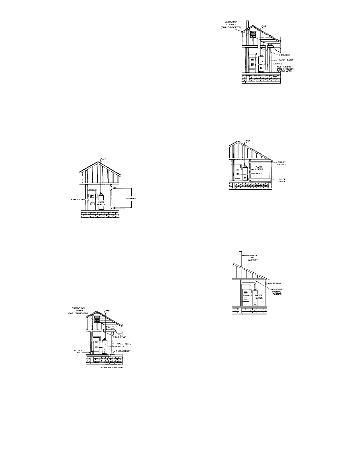
A. ALL AIR FROM INSIDE BUILDINGS: (See Figure 5 and 6)
The confined space shall be provided with two permanent openings
communicating directly with an additional room(s) of sufficient volume
so that the combined volume of all spaces meets the criteria for an
unconfined space. The total input of all gas utilization equipment installed
in the combined space shall be considered in making this determination.
Each opening shall have a minimum free area of one square inch per
1,000 Btu per hour (22 cm
equipment in the confined space, but not less than 100 square inches
(645 cm
2
). One opening shall commence within 12 inches
2
/kW) of the total input rating of all gas utilization
(30 cm) of the top and one commencing within 12 inches (30 cm) of the
bottom of the enclosures.
FIGURE 8.
4. When ducts are used, they shall be of the same cross-sectional
area as the free area of the openings to which they connect. The
minimum short side dimension of rectangular air ducts shall not be
less than 3 inches (7.6 cm), see Figure 9.
FIGURE 6.
B. ALL AIR FROM OUTDOORS: (See Figures 7, 8 and 9)
The confined space shall be provided with two permanent openings,
one commencing within 12 inches (30 cm) of the top and one
commencing within 12 inches (30 cm) from the bottom of the
enclosure. The openings shall communicate directly , or by ducts,
with the outdoors or spaces (crawl or attic) that freely communicate
with the outdoors.
1. When directly communicating with the outdoors, each opening shall
have a minimum free area of 1 square inch per 4,000 Btu per hour
2
(5.5 cm
/kW) of total input rating of all equipment in the enclosure,
see Figure 7.
FIGURE 7.
2. When communicating with the outdoors through vertical ducts, each
opening shall have a minimum free area of 1 square inch per 4,000
Btu per hour (5.5 cm
2
/kW) of total input rating of all equipment in the
enclosure, see Figure 8.
3. When communicating with the outdoors through horizontal ducts,
each opening shall have a minimum free area of 1 square inch per
2,000 Btu per hour (1 1 cm
2
/kW)) of total input rating of all equipment
in the enclosure, see Figure 9.
FIGURE 9.
5. Alternatively a single permanent opening may be used when
communicating directly with the outdoors, or with spaces that freely
communicate with the outdoors. The opening shall have a minimum
free area of 1 square inch per 3,000 BTU per hour (8.3 cm
total input rating of all equipment in enclosure. See Figure 9A.
FIGURE 9A.
6. Louvers and Grilles: In calculating free area, consideration shall be
given to the blocking effect of louvers, grilles or screens protecting
openings. Screens used shall not be smaller than 1/4 inch (6.4 mm)
mesh. If the free area through a design of louver or grille is known,
it should be used in calculating the size opening required to provide
the free area specified. If the design and free area is not known, it
may be assumed that wood louvers will be 20-25 percent free area
and metal louvers and grilles will have 60-75 percent free area.
Louvers and grilles shall be fixed in the open position or interlocked
with the equipment so that they are opened automatically during
equipment operation.
7. Special Conditions Created by Mechanical Exhausting or
Fireplaces: operation of exhaust fans, ventilation systems, clothes
dryers or fireplaces may create conditions requiring special
attention to avoid unsatisfactory operation of installed gas
utilization equipment.
11
2
/kW) of
 Loading...