

Page 1

AHD
Lucht / water warmtepompboiler
Air to water heat pump
Pompe à chaleur air/eau
pour ECS
Luft / Wasser Wärmepumpe
AHD - 290
0309 155
Installatie-, Gebruikers- en
Servicehandleiding
Installation, User and Service Manual
Manuel d’installation, Mode d’emploi,
Manual d’entretien
Installations-, Benutzer- und
Wartungsanleitung
Innovation has a name.
Page 2

uw installateur / your installer / Ihr Installateurvotre installateur /
www.aosmithinternational.com
Page 3

Nederlands 5
English 37
Français 67
Deutsch 99
Page 4

Page 5

Lees deze handleiding
zorgvuldig
Waarschuwing
Lees deze handleiding zorgvuldig voordat u het toestel in gebruik neemt. Het niet
lezen van deze handleiding en het niet opvolgen van de
instructies in deze handleiding kan leiden tot ongevallen en schade aan personen
en het toestel.
Copyright © 2008 A.O. Smith Water Products Company
Alle rechten voorbehouden.
Niets uit deze uitgave mag worden gekopieerd, verveelvoudigd en/of openbaar
gemaakt door middel van druk, fotokopie of op welke andere wijze dan ook,
zonder voorafgaande schriftelijke toestemming van A.O. Smith Water Products
Company.
Handelsmerken
Aansprakelijkheid
Meer informatie
A.O. Smith Water Products Company behoudt zich het recht voor de specicaties
zoals vermeld in deze handleiding te wijzigen.
Alle in deze handleiding genoemde merknamen zijn geregistreerde
handelsmerken van de desbetreffende leveranciers.
A.O. Smith Water Products Company is niet aansprakelijk voor claims van derden
veroorzaakt door ondeskundig gebruik anders dan vermeld in deze handleiding
en overeenkomstig de Algemene Voorwaarden gedeponeerd bij de Kamer van
Koophandel.
Zie verder de Algemene Voorwaarden. Deze kunt u kostenloos bij ons opvragen.
Hoewel grote zorg is besteed aan het waarborgen van correcte en waar nodig,
volledige beschrijving van de relevante onderdelen, kan het voorkomen dat de
handleiding fouten en onduidelijkheden bevat.
Mocht u toch fouten of onduidelijkheden in de handleiding ontdekken, dan vernemen wij dat graag van u. Het helpt ons de documentatie verder te verbeteren.
Indien u opmerkingen of vragen heeft aangaande specieke onderwerpen die
betrekking hebben op het toestel, aarzelt u dan niet contact op te
nemen met:
A.O. Smith Water Products Company
Postbus 70
5500 AB Veldhoven
Nederland
Telefoon: 0800 - AOSMITH
0800 - 267 64 84
Algemeen: +31 40 294 25 00
Fax: +31 40 294 25 39
E-mail: info@aosmith.nl
Website: www.aosmithinternational.com
Voor problemen met de aansluitingen op gas,- elektra- en
watervoorzieningen kunt u terecht bij de leverancier/installateur van uw installatie.
5
Page 6

Inhoudsopgave
A
1. Over het product
1.1 Inhoud van de levering
1.2 Productbeschrijving
1.3 Technische gegevens
1.4 Koelcircuit - beschrijving
1.4.1 Koelsysteem - beschrijving
1.4.2 Elektrisch circuit - beschrijving
1.4.3 Water circuit - beschrijving
1.4.4 Koelcircuit - schema
1.5 Watercircuit – beschrijving
1.5.1 Vereisten voor het watercircuit
1.5.2 Afmetingen
1.5.3 Watercircuit - hydraulisch schema
1.6 Elektrisch schema
2. Voorafgaand aan installatie / in werking
stellen
2.1 Belangrijke veiligheidsinstructies
2.1.1 Koelsysteem – veiligheidsinstructies
2.1.2 Elektrisch circuit - veiligheidsinstructies
2.1.3 Watercircuit - veiligheidsinstructies
2.2 Levering
2.3 Opslag
2.4 Transport
2.4.1 Transport met vorkheftruck
2.4.2 UItladen van de warmtepomp
2.4.3 Transport met steekwagen
2.5 Plaatsing / opstelling
2.6 Aansluiting van de waterleidingen
7
7
7
7
8
8
8
8
9
10
10
10
11
12
13
13
13
13
13
13
12
14
14
14
14
14
15
B
1. Gebruikershandleiding
1.1 Gebruik
1.2 Wijziging van operationele gegevens
1.3 Bedieningsmenu
1.4 Schema fabrieksinstellingen
1.5 Ontdooiprogramma
2. Functie
2.1 Omschrijving
2.2 Extra capaciteit
2.3 Veilig functioneren
2.4 Waarschuwingen
3. Onderhoud
3.1 Koelsysteem en ventilator
3.2 Watercircuit en tank
3.3 Demonteren / De unit buiten gebruik
stellen
4. Opsporen van defecten
4.1 Hogedrukschakelaar
4.2 Veiligheidsschakelaar voor
verwarmingselement
4.3 De warmtepomp loopt niet
5. Garantie
22
22
23
24
27
27
28
28
29
29
29
30
30
30
31
32
32
32
31
33
3. Installatie
3.1 Wateraansluiting
3.2 Plaatsing van de pijpaansluitingen
3.3 Aansluiting condensafvoer
3.4 Luchtinlaat en -uitlaat
3.5 Controle
4. In werking stellen / bediening
4.1 Vereisten voor het watercircuit
4.2 In gebruik nemen van het watercircuit
4.3 In werking stellen van het watercircuit
4.4 Elektriciteit - aansluiting
4.5 Koelcircuit
4.6 Tips voor energiebesparing
4.7 Tips voor ventilator gebruik
4.8 Controle
18
18
18
18
19
19
20
20
20
20
20
20
20
21
21
6
Page 7

A
1. Over het product
Bij de constructie en de bouw van de warmtepomp zijn alle relevante EUrichtlijnen in acht genomen. (Zie eveneens de EU-conformiteitsverklaring.)
Alle werkzaamheden aan deze unit mogen alleen worden uitgevoerd door geschoold personeel. Neem alle noodzakelijke voorzorgsmaatregelen om
ongelukken te voorkomen.
1.1 Inhoud van levering
• Warmtepomp met ingebouwde regelelementen
• Installatiehandleiding met technische gegevens
• Bedieningsinstructies
1.2 Productbeschrijving
De AHD 290 is een water-warmtepomp voor huishoudelijk gebruik met een
condensor aan de buitenzijde van de tank. Toepassing en bedieningsprincipes
worden gespeciceerd in de bedieningsinstructies.
1.3 Technische gegevens
Gegevens betreffende prestaties
Specicaties betreffende prestaties voor opwarming van water van 15°C tot
45°C voor huishoudelijk gebruik
Thermisch vermogen
(bij lucht 15°C / water 15°C – 45°C)
Ingangsvermogen
(bij lucht 15°C / water 15°C – 45°C)
COP
(bij lucht 15°C / water 15°C – 45°C)
Energieverbruik elektrische cartridge / verwarmingselement
Functioneel bereik / grenswaarden
Max. luchttemperatuur °C 35
Max. watertemperatuur °C 55
Max. watertemperatuur
(met functioneren van warmtepomp en elektrische cartridge)
Geluidsniveau
1 meter voor de unit dB(A) 52
kW 1,52
kW 0,43
3,54
kW 1,5
°C 65
Waterreservoir voor huishoudelijk gebruik
Materiaal Speciaal geëmailleerd staal
Netto volume ltr 285
Volume luchtstroom
Volume luchtstroom m³/h 250
7
Page 8

1.4 Koelcircuit – beschrijving
Het koelsysteem wordt gebruikt voor de verwerking van de warmte van de
inlaatlucht. Dit is de manier waarop de onttrokken warmte overgedragen wordt
naar het water. Dit proces is alleen mogelijk door toevoeging van externe
energie, dat plaatsvindt in de compressor.
In de verdamper wordt de warmte uit de lucht geabsorbeerd en gasvormig in de
koelvloeistof naar de compressor gevoerd. In de compressor wordt de koelvloeistof op een hogere druk en een hoger energieniveau gebracht, zodat hij warmte
kan afdragen aan het water via de condensorpijp die rondom de tank is
aangebracht. De gecondenseerde koelvloeistof wordt langzaam onder lagere
druk gebracht met behulp van het drukoverstortventiel, zodat het mogelijk wordt
de koelcyclus in de verdamper te herhalen.
1.4.1 Koelsysteem - beschrijving
Voordat reparatie- en onderhoudswerkzaamheden worden uitgevoerd, dient een
geschoolde technicus te controleren of alle onderdelen die koelvloeistof
transporteren zover leeg zijn dat de werkzaamheden kunnen worden uitgevoerd
zonder enig risico voor personen of materialen.
Bij reparatie- en onderhoudswerkzaamheden aan de warmtepomp waarbij het
koelsysteem moet worden geopend, dient men extra voorzichtig te zijn. Als gebruik van open vuur nodig is (lassen, solderen etc.), dient men extra
voorzorgsmaatregelen te treffen om brand te voorkomen.
1.4.2 Elektrisch circuit - beschrijving
Wanneer er werkzaamheden worden uitgevoerd aan de warmtepomp dient hij
van de stroom te worden afgesloten. (Trek de stekker er uit.)
Wanneer de unit aangesloten is op het stroomnet dient alle lokale en nationale
regelgeving te worden nageleefd evenals de eisen van de stroomleverancier.
1.4.3 Watercircuit - beschrijving
Er mag alleen drinkwater worden gebruikt. Tijdens de installatie dient men te
letten op de keuze van de materialen en dient gecontroleerd te worden of die
compatibel zijn met het volledige circuit. Veiligheidsvoorzieningen dienen te
worden geïnstalleerd om overdruk in het systeem te voorkomen.
Alle pijpverbindingen dienen te voldoen aan de water-veiligheidsvoorschriften.
8
Page 9

1.4.4 Koelcircuit - schema
T5, T6, T7, T8 - Sensoren
Overzicht onderdelen
Nº : Omschrijving
1 Compressor
2 Condensor
3 Verdamper
4 Centrifugaal ventilator
5 Expansieventiel
6 Drooglter
7 Drukschakelaar
8 Magneetklep
9 Eenrichtingsklep
9
Page 10

1.5 Watercircuit – beschrijving
Het watercircuit dient te worden geconstrueerd met inachtneming van de
toepasselijke normen en eisen. Raadpleeg de specicaties in de paragrafen 3.1
en 3.2
1.5.1 Vereisten voor het watercircuit
Onjuiste combinaties van materialen gebruikt in het watercircuit van de woning
kunnen leiden tot schade als gevolg van galvanische corrosie. Daarom is speciale
aandacht vereist bij gebruik van gegalvaniseerde en koperhoudende
componenten.
1.5.2 Afmetingen
Afmetingen (alle maten zijn in mm,
tenzij ander aangegeven)
Omschrijving AHD 290
A Totale hoogte 1815
B Hoogte bovenzijde toestel 1790
D Diameter van het toestel 660
G1 Diameter luchttoevoer 160
G2 Diameter luchtafvoer 160
H Hoogte luchttoe-/afvoer 1815
HX1 x-positie luchttoevoer 190
HX2 x-positie luchtafvoer 480
HY1 y-positie luchttoevoer 200
HY2 y-positie luchtafvoer 470
J Hoogte luchttoevoer 60
M Hoogte koudwatertoevoer 110
N Hoogte warmwateruitlaat 1410
P Hoogte reinigingsopening 45
V Hoogte recirculatie aansluiting 820
W Hoogte condensafvoer 1345
Z Hoogte elektrisch element aansluiting 925
1 Aansluiting koudwateruitlaat (ext.) R 1”
2 Aansluiting warmwateruitlaat (ext.) R 1”
6 Opening reinigen/inspectie Ø 110
7 Aansluiting condensafvoer (inw.) Ø 12
11 Aansluiting elektrische element (inw.) G 1 1/2”
14 Aansluiting recirculatie (inw.) R 1”
10
Page 11

1.5.3 Watercircuit - hydraulisch schema
Legenda
Niet genoemde nummers zijn niet van
toepassing.
1. drukreduceerventiel (verplicht
indien de waterleidingdruk
groter is dan 8 bar)
2. inlaatcombinatie (verplicht)
4. afsluiter (aanbevolen)
5. terugslagklep (verplicht)
6. circulatiepomp (optioneel)
9. aftapkraan
11. service afsluiter (aanbevolen)
12. temperatuurmeter (aanbevolen)
13. condensafvoer (verplicht)
14. tappunten
A. koudwateraansluiting
B. warmwateraansluiting
C. circulatieleiding
11
Page 12

PC-COM
ES852
ICD
T1.6AH
C1 2µF
C
R
S
N
N
B
M
C
D
E
F
A
G
H
J
K
L
L
L
230VAC 50Hz
90°C 2-pol
1
2
3
4
5
6
7
8
9
10
11
12
13
1
1
1
3
2
1
1
1
1
2
2
2
4
4
4
4
4
4
4
4
5
5
1
2
2
3
1
1
2526272829
30
31323334353637
38
1.6 Elektrisch schema
A Besturing
B Ventilator
C Compressor
D Elektrisch element
E Magneetklep
F Display
G Temperatuursensor
(T5)
H Temperatuursensor
(T6)
J Temperatuursensor
(T7)
K Temperatuursensor
(T8)
L Hogedrukschakelaar
M Dubbelpolige
hoofdschakelaar
12
T5 - Sensor voor de spiraal
T6 - Sensor op de spiraal
T7 - Sensor boven in de tank
T8 - Sensor onder in de tank
90° 2-pol
Moet geaard zijn
Page 13

2. Voorafgaand aan
installatie / In werking
stellen
Levering
Warmtepomp inclusief regelunit
Installatiehandleiding met technische gegevens
Handleiding voor regelunit
2.1 Belangrijke veiligheidsinstructies
Bij het ontwerp en de uitvoering van de warmtepomp zijn alle relevante
EU- richtlijnen in acht genomen.
Werkzaamheden aan de warmtepomp mogen alleen door
getraind personeel worden uitgevoerd! Neem alle
noodzakelijke voorzorgsmaatregelen om ongelukken tijdens
de werkzaamheden te voorkomen!
2.1.1 Koelsysteem – veiligheidsinstructies
Voor het begin van de reparatie- en onderhoudswerkzaamheden dient de
geschoolde reparateur te controleren of de onderdelen die koelvloeistof bevatten
tot een dusdanig niveau zijn leeggemaakt dat uitvoering van de werkzaamheden
op verantwoorde wijze en zonder enig gevaar kan plaatsvinden.
Bij reparaties en onderhoud aan de warmtepomp met geopend koelsysteem, en
in het bijzonder bij werkzaamheden met open vuur (solderen, lassen, etc.), dienen
voorzorgsmaatregelen getroffen worden om het ontstaan van de brand te
voorkomen.
2.1.2 Elektrisch circuit – veiligheidsinstructies
Bij werkzaamheden aan de warmtepomp, dient de stroom
altijd te zijn afgesloten - trek de stekker er uit!
Bij aansluiting van de warmtepomp op het stroomnet dient de lokale en nationale
regelgeving te worden nageleefd. Bovendien dient aandacht te worden besteed
aan eisen die mogelijk gesteld worden door de
energieleverancier.
2.1.3 Watercircuit – veiligheidsinstructies
Er mag alleen drinkwater worden gebruikt. Tijdens de installatie dient
aandacht te worden besteed aan de keuze van de materialen en dient men zich
ervan te vergewissen dat die in het gehele circuit zonder problemen gezamenlijk
kunnen functioneren.
Speciale aandacht moet worden besteed bij gebruik van
gegalvaniseerde en aluminiumhoudende onderdelen!
Veiligheidsvoorzieningen dienen te worden geïnstalleerd om overdruk in het
systeem te voorkomen. Alle pijpverbindingen dienen te voldoen aan de
water-veiligheidsvoorschriften.
2.2 Levering
De warmtepomp wordt geleverd zonder water, condenswaterleiding en de
veiligheidsinstallatie voor het watercircuit.
2.3 Opslag
De warmtepomp dient in verticale positie, zonder water en in zijn verpakking te
worden opgeslagen.
13
Page 14

2.4 Transport
Als de warmtepomp voorzichtig over korte afstanden getransporteerd wordt, kan
hij maximaal 45° gekanteld worden. Als deze waarde
overschreden wordt, dient de warmtepomp ten minste gedurende 1 uur in zijn
normale verticale positie te rusten voordat hij gebruikt kan worden.
Transport en opslag kunnen plaatsvinden bij temperaturen tussen -10 en +50°C.
De bovenzijde / behuizing van de warmtepomp zijn niet geschikt om aan opgetild
te worden en dit dient tijdens het transport zorgvuldig vermeden worden.
2.4.1 Transport met vorkheftruck
Voor transport met een vorkheftruck dient de warmtepomp altijd te worden
geplaatst op het bijbehorende transportframe. Breng het geheel altijd langzaam
omhoog. Vanwege de hoge positie van het centrum van de zwaartekracht dient de
warmtepomp tijdens het transport gezekerd te worden tegen omkantelen.
2.4.2 Uitladen van de warmtepomp
Om schade te voorkomen dient de warmtepomp te worden uitgeladen op een vlak
oppervlak.
2.4.3 Transport op steekwagen
De warmtepomp mag alleen worden getransporteerd op het bijbehorende
transportframe.De warmtepomp moet gezekerd worden om te voorkomen dat hij
op de steekwagen van zijn plaats komt.
Wateraansluitingen etc. mogen niet gebruikt worden voor transportdoeleinden.
Zorg ervoor dat de steekwagen niet de kast en de aansluitingen beschadigt.
2.5 Plaatsing / opstelling
De warmtepomp mag alleen geïnstalleerd worden in een vorstvrije ruimte.
De locatie van installatie dient aan de volgende criteria te voldoen:
• Temperatuur in de ruimte tussen 0 en +35°C.
• Afvoermogelijkheid voor condenswater.
• Geen abnormale stofconcentratie in de lucht.
• Een solide ondergrond (ongeveer 500 kg/m²).
• Voor probleemloos functioneren en om toegankelijkheid voor
onderhoud te creëren wordt aanbevolen rondom de unit een 0,5 m
vrije ruimte te laten.
Volgorde van opstelling:
1. Verwijder de pakking van de pallet.
2. Verwijder de transportvoorzieningen van de pallet.
3. Neem de warmtepomp van de pallet en plaats die op de gewenste
locatie.
Stel de warmtepomp in verticale positie af met behulp van de voetjes.
14
Page 15

2.6 Aansluiting van de waterleidingen
Tijdens de installatie moet gelet worden op de actuele druk en drukverlies als
gevolg van de afmetingen van de leidingen, om te zorgen voor voldoende druk
en voldoende waterdoorstroming.
De loodgieterwerkzaamheden dienen te worden uitgevoerd overeenkomstig de
regelgeving.
Voor de leidingen kunnen zowel exibele of rigide materialen gebruikt worden.
Om schade te voorkomen dient men rekening te houden met corrosie.
Net als voor alle andere drukreservoirs dient de warmtepomp te worden
uitgevoerd met veiligheids- en keerkleppen aan de zijde van de toevoer.
De inlaat van het koude water en de afvoer van het warme water bevindt zich
onder de tank (3/4” schroefdraadaansluitingen).
De maximale werkdruk is 10 bar en de maximale bedrijfstemperatuur bedraagt
65°C.
Indien nodig dient de toevoerleiding uitgevoerd te worden met een
drukreduceerventiel en eventueel een lter.
Bij het installeren van de leidingen in de behuizing dient u te allen tijde te
voorkomen dat er vuil in de leidingen komt. (Spoel de leidingen eventueel door
met schoon water voordat de warmtepomp geïnstalleerd wordt)!
Wanneer de leidingen aangesloten worden, let er dan op dat ze niet gedraaid
zitten. Gebruik gereedschap om de leidingen mee vast te houden om verdraaien
te voorkomen!
Indien circulatie niet nodig is, zorg er dan voor dat de circulatieaansluiting
gesloten is!
Wateraansluiting
Onder de warmtepomp bevinden zich de volgende aansluitingen:
Aftapslang condenswater
Koudwaterinlaat / Circulatie / Warmwateruitlaat
Er mogen geen gaten geboord worden. Dat kan de gewikkelde
condensor beschadigen.
1. Schroeven verwijderen (zeshoekige kop).
2. Schroeven die verwijderd dienen te worden.
15
Page 16

3. Schroeven verwijderen.
4. Aaden van product :
a: Laat eht product er aan 1 kant een beetje afglijden.
b: Kantel het product aan dezelfde zijde met daaronder 2 stukken hout.
16
5. Ga door met aaden :
c: Verwijder het onderste gedeelte van de pallet terwijl u het product in
gekantelde positie houdt, met daaronder de 2 stukken hout.
6. Plaats het product op de vloer met de 2 stukken hout.
Page 17

7. Verwijder het 1e stuk hout (dit komt vrij door het product
een beetje naar 1 zijde over te hellen).
8. Verwijder het 2e stuk hout (hel het product daartoe een beetje over naar
de andere zijde).
9. De pallet is verwijderd.
17
Page 18

3. Installatie
3.1 Wateraansluiting
Tijdens de installatie moet er aandacht worden besteed aan de afmetingen van
de leidingen in verband met de waterdruk vooraf en drukverlies om te zorgen voor
voldoende druk en waterdoorstroming bij het tappunt.
De maximale werkdruk is 10 bar en de maximale bedrijfstemperatuur 65°C. Indien
nodig moet de toevoerleiding worden uitgerust met een drukreduceerventiel en
eventueel een lter.
Zoals alle drukreservoirs dienen de aansluitingen van de warmtepomp eveneens
te worden voorzien met een goedgekeurde veiligheidsklep aan de afgiftezijde en
een keerklep aan de toevoerzijde.
Alle pijpverbindingen dienen te voldoen aan de water-veiligheidsvoorschriften.
3.2 Plaatsing van de pijpaansluitingen
De warmwateruitlaat is gemonteerd op de bovenste
aansluiting. (¾” RG)
Als de unit gebruikt wordt met circulatie van de
warmwatertoevoer, wordt de middelste aansluiting gebruikt
als retourleiding. (¾” RG)
De inlaat van vers koud water is gemonteerd op de onderste
aansluiting. (¾” RG)
Aangeraden wordt om voor de wateraansluiting een ¾” exibele leiding te gebruiken om eventueel lawaai door vibreren te
voorkomen.
Er mogen voor montagedoeleinden e.d. geen gaten worden
geboord in het product! Daarmee zou afbreuk kunnen worden
gedaan aan het correcte functioneren van het product waar
door het waardeloos wordt.
3.3 Aansluiting condenswaterafvoer
Tijdens het functioneren van de warmtepomp zal er condenswater ontstaan dat naar de aansluiting voor de aftapleiding
zal worden gevoerd (1).
De hoeveelheid condenswater hangt af van de vochtigheid
van de lucht die via de inlaat in de warmtepomp terechtkomt.
18
De aansluiting voor het condenswater moet uitgevoerd zijn
met een slang met een goed sluitend luchtslot en dient naar
een afvoer te leiden. Het luchtslot dient een waterkolom te
bevatten van tenminste 60 mm.
Het is eveneens mogelijk andere luchtsloten te gebruiken, zoals een slang met
een bocht.
Als er geen luchtslot wordt aangebracht kan er waterschade
of schade aan de warmtepomp ontstaan! Als het luchtslot niet
op correcte wijze is aangebracht, zal de garantie niet van
toepassing zijn!
Page 19

3.4 Luchtinlaat en -uitlaat
Zorg ervoor dat er rondom de warmtepomp voldoende vrije ruimte is.
Inlaatlucht
De inlaatlucht mag niet vervuild zijn met agressieve bestanddelen (ammonia,
zwavel, chloor, etc.). Daardoor kunnen delen van het systeem beschadigd raken.
Luchtaansluitingen
Inlaat- en afvoerleidingen dienen te worden gemaakt van gladde buizen om drukverlies te minimaliseren. Let tijdens de installatie op de werkdruk van de ventilator en
de leidingweerstand. (Zie de technische gegevens.)
Aangeraden wordt de luchtkanalen die in de buurt van de warmtepomp geplaatst
worden waterpas of met een licht verval in de richting van de uitlaat van de
afgezogen lucht te plaatsen om het lekken van condenswater te voorkomen. Ze
moeten makkelijk kunnen worden gesloten. Daarmee wordt voorkomen dat er
condenswater uit de leidingen lekt. Wanneer er luchtkanalen geplaatst worden aan
de buitenzijde van het gebouw dient er een terugslagklep (met een kleine
weerstand) geplaatst te worden om te voorkomen dat er in de winter koude lucht de
ruimte binnenkomt wanneer de warmtepomp stilstaat.
De warmtepomp mag alleen gebruikt worden bij een volle tank!
De unit moet altijd van de stroom worden afgesloten voordat de klep
aan de voorzijde verwijderd wordt. Nadat u de unit van de stroom
heeft afgesloten, dient u eerst te wachten tot de ventilator tot
stilstand gekomen is voordat u de kleppen aan de voorzijde opent.
Voordat u de unit opstart dient u te controleren of alle kabels en
elektrische verbindingen correct zijn aangesloten en of de kabel en
de stekker die de display in de deur en de printplaat verbinden
correct geplaatst zijn.
Het wordt aangeraden om alle leidingen te isoleren om het warmteverlies te
verminderen en het geluidsniveau te verlagen.
3.5 Controle
Aangeraden wordt om na de installatie inspecties uit te voeren om te controleren of
de aansluitingen dicht zijn en de afvoer van het condenswater niet geblokkeerd is.
19
Page 20

4. In werking stellen /
bediening
De warmtepomp mag alleen gestart worden met een volle watertank!
De unit moet altijd van de stroom worden afgesloten wanneer de klep aan de
voorzijde geopend wordt!
Na afsluiten van de unit dient u te wachten totdat de ventilator volledig tot stilstand
is gekomen voordat u de klep opent!
Voordat u de unit opstart dient u te controleren of alle aansluitingen gemaakt zijn
en of de kabel tussen de display en het regelunit correct is gemonteerd!
4.1 Vereisten voor het warmwatercircuit
In het warmwatersysteem mogen de volgende materialen gebruikt worden:
- Koper
- Roestvrij staal
- Messing
- Plastic
Afhankelijk van de materialen die gebruikt zijn in het watercircuit (in het huis)
kunnen verkeerde materiaalcombinaties leiden tot corrosieschade. Speciale
aandacht is vereist bij het gebruik van gegalvaniseerd staal of aluminium.
4.2 In gebruik nemen van het watercircuit
- Vul de tank via het ventiel in de toevoerleiding en laat de lucht
ontsnappen via een van de bovenste warmwaterkranen totdat er geen
lucht meer aanwezig is in het kraanwater.
- Controleer het volledige watercircuit op waterdichtheid.
- Sluit de warmtepomp aan op het stroomnet.
Na de ingebruikname van het systeem dient het volledige watercircuit te worden
gecontroleerd op waterdichtheid.
4.3 In werking stellen van het watercircuit
Vul het reservoir via de aansluiting en laat de lucht uit de tank ontsnappen door
een van de warmwaterkranen op het hoogste punt in de woning open te laten
staan totdat er geen lucht meer met het water uitstroomt.
Het reservoir kan normaalgesproken 285 liter water bevatten.
Controleer het volledige circuit op waterdichtheid.
4.4 Elektriciteit – aansluiting
Sluit de warmtepomp aan op het openbare stroomnet.
4.5 Koelcircuit
Het koelcircuit wordt gebruiksklaar geleverd en er hoeven geen werkzaamheden
aan te worden uitgevoerd. De elektronische regelelementen voeren automatisch
alle functies uit met betrekking tot de bediening van de compressor en de
ventilator.
Indien nodig stelt u de regelelementen in op de gewenste watertemperatuur. Het
koelcircuit staat af fabriek ingesteld op 50°C (Raadpleeg de bedieningsinstructies
voor meer gedetailleerde aanwijzingen).
20
4.6 Tips voor energiebesparing
Stel de watertemperatuur niet hoger in dan nodig is.
De warmtepomp functioneert het effectiefst bij lage watertemperaturen.
Het gebruik van circulatie zal het energieverbruik van de warmtepomp aanzienlijk
doen toenemen.
Page 21

4.7 Tips voor ventilatorgebruik
Wanneer u een kanaalsysteem gebruikt is het wellicht nodig om de ventilator op
een hogere snelheid te laten draaien om drukverlies te compenseren.
4.8 Controle
Na voltooiing van de installatie wordt aangeraden om alle verbindingen etc. te
controleren om er zeker van te zijn dat alle afsluitingen waterdicht zijn en dat het
condenswater ongehinderd kan afgevoerd worden.
Voor periodiek onderhoud raadpleegt u de gebruikershandleiding.
21
Page 22

B
1. Gebruikers handleiding
De AHD 290 wordt geleverd met fabrieksinstellingen, waardoor onmiddellijk
opstarten van de unit mogelijk is. De fabrieksinstellingen zijn elementair en dienen
te worden aangepast aan de operationele eisen en behoeften van het desbetreffende huis om de functionele voordelen van de unit optimaal te benutten.
1.1 Gebruik
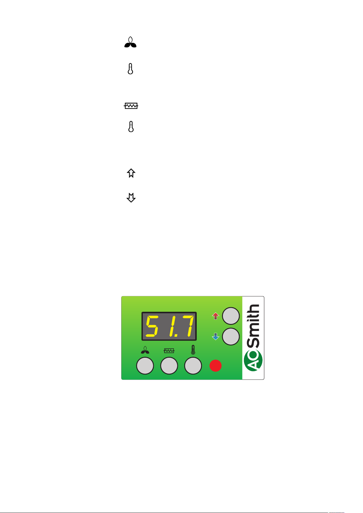
Gebruikersmenu
De waarde van een bepaald menuonderdeel wordt getoond wanneer u
onderstaande toets/toetscombinatie indrukt. De waarde kan gewijzigd worden met
de pijlen wanneer u tegelijkertijd de toets/toetscombinatie ingedrukt houdt. De
regelunit zal terugkeren naar de standaardweergave wanneer er gedurende ca.
15 seconden geen knoppen ingedrukt zijn.
P1: Niveau
De niveautoets is ingedrukt
Met deze toets is het mogelijk te schakelen tussen:
stand-by, automatisch functioneren, constant functioneren en
timer-aangestuurd constant functioneren. (niveau 0, niveau 1, niveau 2,
niveau 3)
Niveau 0: De warmtepomp is nu uitgeschakeld en de regelunit is actief.
Niveau 1: De ventilator draait alleen wanneer er water voor huishoudelijk
gebruik wordt opgewarmd. (1. voorrang)
Niveau 2: De ventilator draait alleen nadat de compressor gestopt is en
onttrekt warmte voor het huis. (E18)
Niveau 3: De ventilator draait gedurende een geselecteerde periode daarna schakelt die terug naar normaal functioneren.
Fabrieksinstelling: 1
P2: Elektrisch element AAN
De toets van het elektrische element is ingedrukt
De warmtepompen functioneren met een extra verwarmingselement voor
de verwarming van water voor huishoudelijk gebruik. Met deze toets kan
het elektrische element voor de opwarming van water voor
huishoudelijk gebruik ingeschakeld worden. Door de waarde 1 in te
stellen zal het elektrische element ingeschakeld worden wanneer dat
nodig is. Door de waarde 0 in te stellen zal het elektrische element niet
ingeschakeld worden wanneer dat nodig is. Bij een buitentemperatuur van
minder dan 0°C is het nuttig het elektrische element te gebruiken.
Fabrieksinstelling: 0
22
P3: De thermostaat is ingeschakeld
De gewenste temperatuur van het water kan worden ingesteld tussen
0-55°C; de opwarming wordt uitgevoerd door de warmtepomp.
Fabrieksinstelling: 50°C
Page 23
P4: Ontdooien uitschakelen
De niveautoets en de toets van de functionerende thermostaat worden
tegelijkertijd ingedrukt
+
Als standaardinstelling wordt de ontdooiperiode beëindigd wanneer de
temperatuur de 10°C bereikt heeft. Bij functioneren onder buitengewone
omstandigheden is het wellicht nodig deze temperatuur te wijzigen. De
temperatuur kan worden ingesteld op waarden tussen 0-25°C.
Fabrieksinstelling: 10°C
P5: Het elektrische element
De toetsen van het elektrische element en de thermostaat worden
+
tegelijkertijd ingedrukt
De temperatuur van het water voor huishoudelijk gebruik kan worden
ingesteld tussen 0-65°C. Het elektrische verwarmingselement verwarmt
enkel de bovenste helft van het reservoir, terwijl de warmtepomp nog
steeds de onderste helft van het reservoir verwarmt.
Fabrieksinstelling: 50°C
Displayweergave
Het is mogelijk om verschillende temperaturen op de display te bekijken
door de pijlen in te drukken totdat de gewenste temperatuur getoond is. Na
ca. 5 seconden wordt de temperatuur weergegeven. De temperatuur wordt
gedurende ca. 30 seconden weergegeven, waarna de display terugkeert
naar de standaardweergave. De volgende temperaturen kunnen getoond
worden:
T4: Extra sensor voor gewoon gebruik of voor input voor gedwongen
functioneren
T5: Voorkoeloppervlak
T6: Koeloppervlak
T7: Bovenzijde water voor huishoudelijk gebruik
T8: Onderzijde water voor huishoudelijk gebruik
T9: Extra sensor
1.2 Wijziging van operationele gegevens
Normaal toont de display de watertemperatuur.
Druk gedurende ca. 10 seconden tegelijkertijd (pijl omhoog) en (pijl omlaag) in om
toegang te krijgen tot het bedieningsmenu. Om de geselecteerde waarde te tonen
drukt u op de knop met temperatuur. De display zal nu het eerste punt E0 van het
bedieningsmenu weergeven. Het bedieningsmenu zal sluiten en terugkeren naar
het hoofdmenu wanneer er gedurende 15 sec. geen knop is ingedrukt.
Als u door het bedieningsmenu wilt lopen, kunt u dat doen door (pijl
omhoog) of (pijl omlaag) in te drukken. De waarde van een punt wordt getoond
wanneer u drukt op de (temp knop). De waarde kan gewijzigd worden met
(pijl omhoog) of (pijl omlaag) wanneer tegelijkertijd de (temp knop) ingedrukt wordt.
De regelunit zal terugkeren naar de standaardweergave wanneer er gedurende
ca. 15 seconden geen
knoppen ingedrukt zijn.
23
Page 24

1.3 Bedieningsmenu
E0: Fabrieksinstelling
Als het systeem niet functioneert zoals verwacht, zelfs wanneer de waarden zijn
bijgesteld, en het onmogelijk is de oorzaak te lokaliseren, is het aan te raden om
de instellingen in het schema te noteren. Daarna stelt u de waarde in op 1 en wacht
tot de regelunit terugkeert naar de
standaardinstellingen. Nu zijn alle waarden teruggezet naar de
fabrieksinstellingen. U kunt nu opnieuw beginnen en de waarden
instellen.
Fabrieksinstelling: 0
E2: T9 temperatuur instellen
Met deze sensor kan relais R9 worden aangestuurd, dat zal worden geactiveerd wanneer de waarde E2 bereikt wordt. Het R9 relais kan worden gebruikt
om de driewegklep van de uitlaatlucht aan te sturen. Deze driewegklep kan het
woongedeelte voorzien van koude lucht wanneer de ruimte de waarde E2 bereikt.
U heeft voor deze functie een aparte sensor nodig die niet standaard meegeleverd
wordt. De sensor moet worden aangesloten op het bedieningspaneel. Om toegang
te krijgen tot het bedieningspaneel dient u de bovenzijde van de machine te verwijderen.
E2 kan ingesteld worden tussen 10-30°C
Fabrieksinstelling: 21°C
E8: Functie desinfectie AAN/UIT
Door de waarde op 1 in te stellen, zal de elektrische cartridge eenmaal per week
warm water met een temperatuur van 65°C leveren om de tank te desinfecteren
(anti-legionella functie)
Fabrieksinstelling: 0
E9: Functioneren in koude omgevingen AAN/UIT
Als de waarde op 0 is ingesteld, zal de warmtepomp zo lang draaien als er behoefte is aan warmte (= uitlaatlucht-functie).
Bij gebruik van de warmtepomp met aanvoer van inlaatlucht uit bijv. de kelder
bestaat de optie de compressor uit te schakelen wanneer de ruimte te koud wordt.
In plaats daarvan zal het elektrische verwarmingselement het water opwarmen.
De functie wordt geactiveerd wanneer de waarde is gesteld op 1 (=circulatieluchtfunctie).
Het is ook mogelijk om het elektrische verwarmingselement automatisch in te
schakelen om te helpen bij de verwarming van het water wanneer de temperatuur van de inlaatlucht beneden de in E10 ingestelde temperatuur ligt. De functie
wordt geactiveerd wanneer de waarde is gesteld op 2 (= frisselucht-functie). Als de
waarde 0 is, is de functie niet actief.
Fabrieksinstelling: 0
E10: Functioneren in koude omgevingen
Wanneer de functie E9 wordt geactiveerd, kan de temperatuur ingesteld worden
waarbij de compressor zal uitschakelen of het verwarmingselement ondersteuning
zal geven. De temperatuur kan worden ingesteld tussen -10 en +10°C.
Fabrieksinstelling: -5
E15: Hygrostaat / stop unit
Als de waarde 0 is, zal de snelheid van de ventilator wijzigen naar 3 wanneer de
relatieve vochtigheid boven de vooraf ingestelde waarde van de hygrostaat ligt. Als
de waarde 1 is, zal de unit stoppen wanneer de clips 25 en 26 contact met elkaar
maken.
Fabrieksinstelling: 0
24
Page 25

E16: Min. luchtstroom
Deze waarde laat de minimale snelheid zien waarbij de ventilator mag draaien
wanneer het systeem functioneert. Let erop dat het koelsysteem overbelast kan
raken, waardoor de hogedrukschakelaar het circuit onderbreekt wanneer de
waarde te hoog is ingesteld. De geselecteerde waarde mag niet hoger liggen dan
noodzakelijk om een minimale luchtstroom over het koeloppervlak te garanderen.
Deze waarde kan ingesteld worden tussen 0-100%.
Fabrieksinstelling: 0
E17: Langdurige luchtstroom AAN
In de 3e snelheid bestaat de mogelijkheid om de unit automatisch na een aantal
uren terug te laten schakelen naar de 2e snelheid door die in te stellen op waarde
1. Als de waarde op 0 is ingesteld, zal de unit in de 3e snelheid blijven draaien
totdat er handmatig een lagere snelheid wordt geselecteerd.
Fabrieksinstelling: 0
E18: Uren
Als de automatische terugschakeling in de 3e snelheid is ingesteld, kan het aantal uren dat de unit moet functioneren met ingeblazen lucht hier worden ingesteld.
De waarde kan worden ingesteld tussen 1-10 uur.
Fabrieksinstelling: 3
E19: Extra functie
Als de waarde op 1 is ingesteld, zal de extra functie worden geactiveerd zodra T9
de ingestelde waarde bereikt (se E2). Als de waarde op 0 is ingesteld, zal deze
functie niet actief zijn.
E21: TX-instelling
Om hoge werkdruk in het koelsysteem te voorkomen, dient het vermogen van
het systeem voor het resterende gedeelte van de verwarmingsperiode te worden
gereduceerd. Deze parameter geeft de watertemperatuur aan waarbij de reductie
dient te beginnen. Deze kan worden ingesteld tussen 0-55°C.
Fabrieksinstelling: 45
E23: Tmop
Deze waarde geeft de maximaal toegestane verdampingstemperatuur aan. Hiermee wordt overbelasting van het compressorsysteem bij hoge omgevingstemperaturen voorkomen.
Deze waarde kan ingesteld worden tussen 0-20℃.
Fabrieksinstelling: 15
E25: Ontluchtingsniveau 2
Als er een langere periode van ontluchting van het gebouw gewenst is, is het
mogelijk over te schakelen naar niveau 2. De ventilator zal nu zo lang blijven
draaien totdat er een ander niveau geselecteerd wordt. Deze optie wordt gebruikt
om de snelheid in te stellen waarmee de ventilator dient te draaien, wanneer
niveau 2 geselecteerd is. Let erop dat bij deze instelling eveneens de maximale
snelheid van de ventilator wordt ingesteld wanneer die draait op niveau 1. De
snelheid kan worden ingesteld van 0-100%.
Fabrieksinstelling: 100
E26: Ontluchtingsniveau 3
Als de ontluchting van het gebouw gedurende een specieke periode gewenst
wordt, is het mogelijk over te schakelen naar niveau 3. De ventilator zal nu gedurende de ingestelde periode draaien. Daarna zal het systeem terugkeren naar
niveau 2. Deze menuoptie wordt gebruikt om de snelheid te bepalen waarmee
de ventilatoren dienen te draaien wanneer de ingestelde periode geselecteerd is.
Let u erop dat bij deze instelling eveneens de maximale snelheid van de ventilator wordt ingesteld wanneer die draait op niveau 1. De snelheid kan worden
ingesteld van 0-100%.
Fabrieksinstelling: 100%
25
Page 26

E27:
Beschikbare functie. Deze dient altijd 1 te zijn.
E45: dTair-instelling
Hiermee kunt u kiezen voor minimale koeling van de lucht wanneer het water
wordt verwarmd. De regelunit zal de snelheid van de ventilator aanpassen om te
garanderen dat de lucht gekoeld wordt op exact de geselecteerde temperatuur.
Indien de regelunit om technische redenen de lucht moet afkoelen, zal de waarde
worden bewaakt door de automatische functie. Wanneer een hogere ventilatorsnelheid gewenst wordt, kan de waarde worden verlaagd. Vergeet echter
niet dat bij te laag ingestelde waarden de ventilator sneller zal draaien en meer
energie zal gebruiken.
Fabrieksinstelling: 2
26
Page 27

1.4 Schema fabrieksinstellingen
Fabrieksinstellingen Datum Datum
E0 : Fabrieksinstelling 0 0
E2 : Ingestelde temperatuur
E8 : Functie desinfectie AAN/UIT 0
E9 : Funtioneren in koude omgevingen
E10 : Functioneren in koude omgevingen
E15 : Hygrostaat / stop unit
E16 : Min. luchtstroom 0
E17 : Ingeblazen lucht AAN
E18 : Uren
E19 : Extra functie
E21 : TX-instelling 50
E23 : Tmop 25
E25 : Ontluchtingsniveau 2
E26 : Ontluchtingsniveau 3
E27 :
E45 : dTair instelling 1
1.5 Ontdooiprogramma
T5 voor spiraal °C T6 in spiraal °C
15° -3°
13° -3°
11° -3°
9° -4°
7° -4°
5° -5°
4° -5°
3° -6°
1° -7°
0° -8°
-2° -9°
-5° -11°
-7° -13°
-9° -13°
-11° -15°
-13° -16°
-15° -18°
-17° -20°
-18° -21°
-20° -22°
27
Page 28

2. Functie
2.1 Omschrijving
Het stroomschema toont de locatie van de sensoren, terwijl de printplaat de
uitgangen van het relais en de andere uitgangen voor de aansluiting van de
ventilator en bedieningspaneel toont.
Gebruik van de warmtepomp voor warm leidingwater:
De warmtepomp is enkel bedoeld om warm leidingwater voor huishoudelijk
gebruik te produceren binnen de gespeciceerde temperatuurwaarden. De
sanitaire warmwater-warmtepomp is een complete unit met een tank van 285 liter
warm water, afzuigventilatoren, warmtepomp, tevens voorzien van een complete
elektrische uitrusting; vijf modellen zijn voorzien van een verwarmingsspiraal.
Capaciteit:
De warmtepomp kan een hoeveelheid warm water produceren van ca. 1000 liter
van 45°C. Het werkelijke volume hangt af van de temperatuur van het
aangevoerde koude water, de luchttemperatuur en de wijze waarop het warme
water gebruikt wordt. Het extra elektrische verwarmingselement (1,5 kW) kan
gebruikt worden om de capaciteit te verhogen wanneer dat nodig is. De
warmtepomp gebruikt slechts ca. 27% van de energie die door een conventionele
elektrische boiler gebruikt wordt.
Werking van de warmtepomp:
De regelunit start de compressor korte tijd nadat er warm water gebruikt is. De
compressor zal functioneren totdat de hele tank opnieuw tot de ingestelde
temperatuur opgewarmd is. Normaal gesproken kan de warmtepomp een
hoeveelheid warm leidingwater produceren die voldoende is voor de behoefte van
een normaal gezin.
Verwarmen van water:
Wanneer er warm water onttrokken wordt, zal de tank onderin worden bijgevuld
met koud water. Een sensor meet de temperatuur aan de onderzijde van de tank
en start de compressor wanneer de temperatuur gezakt is tot 5°C onder de
ingestelde temperatuur. De compressor stopt wanneer het water verwarmd is tot
op de ingestelde temperatuur. Terwijl de compressor functioneert, draaien de
ventilatoren en laten ze lucht langs de koelspiraal circuleren.
Werking van de ventilator:
De ventilator kan door de selectie van niveau 2 of niveau 3 zo worden ingesteld dat
hij constant draait nadat de compressor uitgeschakeld is. Deze optie kan
geselecteerd worden wanneer de warmtepomp gebruikt wordt als een
afzuigsysteem in de vochtige ruimtes van de woning. Als het ingangsvermogen
op T4 geschakeld wordt, zal de regelunit gedwongen worden op de 3e snelheid te
draaien. Deze optie kan gebruikt worden om een hogere afzuigcapaciteit te
bereiken in bijv. de badkamer wanneer er gedoucht wordt. Wanneer de
doorschakeling naar T4 verbroken wordt, zal de regelunit terugkeren naar de
vorige stap.
Ontdooien:
Wanneer het temperatuurverschil tussen de temperatuur van de lucht aan de
bovenzijde van het koeloppervlak en het koeloppervlak te groot wordt (wat het
geval is wanneer er ijs gevormd wordt op het koeloppervlak) schakelt de unit naar
de modus ontdooien. De magneetklep MA 4 gaat open en de ventilator die de
lucht aanvoert zal uitschakelen totdat het ijs gesmolten is en het koeloppervlak een
temperatuur heeft bereikt van ca. 5°C. De magneetklep gaat dan weer dicht en de
ventilator voor de luchtaanvoer zal weer gaan werken.
28
Page 29

2.2 Extra capaciteit
Als er zich een situatie voordoet waarin de warmtepomp niet in staat is voldoende
warm leidingwater te produceren, kan er een extra elektrisch verwarmingselement
ingeschakeld worden. Daardoor wordt het mogelijk meer water te verwarmen. Het
is mogelijk de gewenste temperatuur in te stellen waarnaar het elektrische
verwarmingselement het water dient op te warmen. (Gebruik het elektrische
verwarmingselement alleen wanneer dat nodig is, aangezien dit meer energie
verbruikt dan de compressor). Het elektrische verwarmingselement wordt
handmatig geactiveerd op de display.
2.3 Veilig functioneren
Hogedrukschakelaar:
Om te voorkomen dat de compressor zijn functiebereik overschrijdt, is er een
hogedrukschakelaar die zorgt voor uitschakeling wanneer de druk te hoog wordt.
Druk op de rode resetknop wanneer de oorzaak van de fout gevonden is.
Wanneer de hogedrukschakelaar het circuit onderbreekt, zal de rode LED gaan
knipperen totdat de rode resetknop geactiveerd wordt. Om een herhaling van een
drukschakelaarfout te voorkomen, kan de watertemperatuur 2-3°C lager worden
ingesteld.
Veiligheidsschakelaar voor het elektrische verwarmingselement:
Als er zich een fout voordoet in het verwarmingselement, wordt de veiligheidsschakelaar geactiveerd en schakelt het verwarmingselement uit om te voorkomen
dat de tank oververhit raakt.
Zorg ervoor dat bij werkzaamheden aan de warmtepomp de
stroom altijd uitgeschakeld is. Werkzaamheden aan deze unit
mogen alleen worden uitgevoerd door getraind personeel!
2.4 Waarschuwingen
Hogedrukschakelaar:
Wanneer de drukschakelaar eruit klapt, zal het rode licht op de display aangaan
totdat de drukschakelaar gereset wordt.
29
Page 30
3. Onderhoud
De volgende instructies dienen te worden opgevolgd om optimaal functioneren van
de warmtepomp te garanderen.
De stroomtoevoer naar het systeem moet altijd uitgeschakeld
worden voordat de klep van de warmtepomp geopend wordt.
Wanneer de unit voor eerste keer geïnstalleerd is, controleer dan na een paar dagen de wateraansluitingen om er zeker van te zijn dat er geen lekken zijn.
Controleer eveneens of de condensafvoerleiding niet geblokkeerd is.
Milieu-overwegingen
Wanneer er onderhoud wordt uitgevoerd aan de unit of wanneer hij niet langer
gebruikt wordt, zorg er dan voor dat de richtlijnen voor hergebruik en verwijdering
van alle materialen worden opgevolgd in overeenstemming met de lokale
procedures en wetten.
3.1 Koelsysteem en ventilator
Ventilator:
Onderhoud aan de ventilatoren bestaat hoofdzakelijk uit periodiek schoonmaken
van de verdamper. Maak de exibele slangen los van de bovenkant van de unit en
schroef de bovenplaat eraf. Maak de ventilator schoon met een borstel. Verwijder
niet de blokjes van het aandrijfmechanisme die zorgen voor evenwicht, omdat er
daardoor onbalans ontstaat, hetgeen resulteert in meer lawaai en slijtage van de
ventilator.
Gevaar op letsel door de scherp afgekante rotorbladen! Beschadig
deze rotorbladen niet!
Condensafvoer:
Wanneer u in de herfst de lters vervangt, controleer dan de condensafvoerleiding
en -bak op verstopping door vuil. Vul de condensbak met water en controleer of het
water er ongehinderd uitloopt. Indien dit niet het geval is, moet de afvoer schoongemaakt worden. Zorg er tegelijkertijd voor dat de verdamperplaten schoon zijn.
3.2 Watercircuit en tank
Veiligheidsklep:
De installateur heeft een veiligheidsklep op de koudwater-toevoerleiding van de
warmwatertank gemonteerd. Deze klep is een beveiligingsmechanisme voor de
tank tegen te hoge druk wanneer het water tijdens de verhitting uitzet.
De terugslagklep, die gemonteerd is vóór de veiligheidsklep op de
koudwaterleiding, voorkomt dat er water terugstroomt in de koudwaterleiding. Dat
betekent dat de druk in de tank zal toenemen tot aan de maximale druk die de
veiligheidsklep toelaat; die zal dan opengaan en het teveel aan water laten
ontsnappen. Als de veiligheidsklep niet open zou gaan, zou de tank barsten.
Om er zeker van te zijn dat de veiligheidsklep correct functioneert, dient die
meerdere keren per jaar geïnspecteerd te worden. Daartoe drukt u op het geveerde
gedeelte van de veiligheidsklep en kijkt of er water uit de klep stroomt. Schade als
gevolg van een geblokkeerde veiligheidsklep wordt niet gedekt door de garantie.
30
Page 31

Anode:
Om corrosie van de geëmailleerde warmwatertank te voorkomen is de tank
uitgevoerd met een magnesiumanode met een ¾“ sluitschroef. Deze anode heeft
een verwachte levensduur van 2-5 jaar. Het is desondanks belangrijk steeds te
controleren of de anode intact is. Dat moet worden gedaan door de anode
eenmaal per 2 jaar te controleren en die te vervangen wanneer die gecorrodeerd is
en een diameter heeft van nog maar 6-10 mm. Om de anode te controleren schakelt
u het systeem af van het stroomnet en verwijdert u de frontplaat. U dient het water
uit de warmwatertank te laten lopen voordat de anode kan worden losgeschroefd.
Daartoe sluit u de koudwatertoevoer en bevestigt u een slang aan de aftapkraan
om ervoor te zorgen dat het water naar het dichtstbijzijnde afvoerpunt geleid wordt.
Tijdens het aftappen van het water uit de tank moet u een warmwaterkraan open
draaien om te voorkomen dat er onderdruk in de tank ontstaat. Wanneer de tank
leeg is, kan de anode worden losgeschroefd en geïnspecteerd worden. Wanneer
de anode opnieuw is aangebracht, sluit u de aftapkraan en draait u de kraan van
de watertoevoer weer open om de tank met water te vullen. Wanneer de tank vol is
en de frontplaat weer is aangebracht, kan de stroom weer ingeschakeld worden.
3.3 Demonteren / De unit buiten gebruik stellen
De volgende acties moeten ondernomen worden:
Sluit de unit van de stroom af en verwijder andere aansluitingen. Draai de
koudwaterkraan dicht en sluit een slang aan op de aftapkraan om het water af te
tappen. Terwijl u het water aftapt, dient u een warmwaterkraan te openen om te
voorkomen dat er onderdruk in de tank ontstaat. De aansluitingen op de
luchtkanalen zijn niet aangebracht en de overige luchtkanalen dienen te worden
gesloten om te voorkomen dat er condenswater in het gebouw terechtkomt.
31
Page 32

4. Opsporen van
defecten
De warmtepomp is uitgevoerd met de volgende veiligheidsvoorzieningen:
4.1 Hogedrukschakelaar
Om te voorkomen dat de compressor zijn functiebereik overschrijdt, is er een
hogedrukschakelaar die zorgt voor uitschakeling wanneer de druk te hoog wordt.
Bij onderbrekingen (druk te hoog) zal het rode licht op het bedieningspaneel
knipperen en zal de hogedrukschakelaar de warmtepomp uitschakelen. Het rode
licht gaat branden. Start de installatie opnieuw op door handmatig de
hogedrukschakelaar te resetten.
Voor het handmatig resetten van de hogedrukschakelaar, kan de frontplaat worden
verwijderd door de schroeven los te draaien.
Voor RESET, verwijdert u de plastic stop aan de bovenzijde en drukt u op de rode
knop.
4.2 Veiligheidsschakelaar voor verwarmingselement
De veiligheidsschakelaar beschermt de installatie tegen oververhitting tijdens de
verwarming met het elektrische verwarmingselement.
De veiligheidsschakelaar is gemonteerd op het verwarmingselement. Als de
ingestelde waarde (90°) overschreden wordt, zal de verwarmingsspiraal
uitgeschakeld worden. Deze kan opnieuw ingeschakeld worden wanneer de
temperatuur lager is dan 90°. Daartoe moet de installatie van de stroom zijn
afgesloten. Nu kan de resetknop ingedrukt worden.
Attentie: Zorg ervoor dat u de kabels naar de regelunit niet beschadigt of lostrekt.
4.3 De warmtepomp loopt niet
Controleer of:
• de stroom is ingeschakeld;
• er stroom staat op het stopcontact;
• de watertemperatuur de ingestelde waarde heeft bereikt;
• de temperatuur van het leidingwater lager is dan 55°C;
• de kabel tussen de regelunit en de display aangesloten is.
Als u hiermee de fout niet kunt opsporen, wordt u verzocht contact op te nemen
met uw lokale installateur of onderhoudsmonteur.
32
Page 33

5. Garantie(certicaat)
Voor registratie van uw garantie dient u de bijgevoegde garantiekaart
ingevuld te retourneren waarna u een garantiecerticaat wordt toegestuurd. Dit
certicaat geeft de eigenaar van een door A.O. Smith Water Products Company
B.V. te Veldhoven, Nederland (hierna “A.O. Smith”) geleverd
toestel recht op de hierna omschreven garantie, waartoe A.O. Smith zich jegens
de eigenaar verbindt.
Garantie algemeen
Garantie tank
Voorwaarden installatie
en gebruik
Indien binnen één jaar na de oorspronkelijke installatiedatum van een door A.O.
Smith geleverde boiler, na onderzoek en ter uitsluitende beoordeling van A.O.
Smith, blijkt dat een deel of onderdeel, met uitzondering van de tank, niet of niet
juist functioneert ten gevolge van fabricage- en/of
materiaalfouten, zal A.O. Smith dit deel of onderdeel vervangen of
repareren.
Indien binnen 3 jaar na de oorspronkelijke installatiedatum van een door A.O.
Smith geleverde boiler, na onderzoek en ter uitsluitende
beoordeling van A.O. Smith, blijkt dat de stalen glasslined tank lekt ten gevolge
van roest of corrosie vanuit de waterzijdige kant, zal A.O. Smith een volledig
nieuwe boiler van gelijkwaardige grootte en kwaliteit ter beschikking stellen. Op
de ter vervanging beschikbaar gestelde boiler zal een garantie gegeven worden
voor de duur van de resterende garantieperiode van de oorspronkelijk geleverde
boiler. In afwijking van het in artikel 2 bepaalde geldt, dat de garantieduur wordt
teruggebracht tot één jaar na de
oorspronkelijke installatiedatum indien ongeltreerd of onthard water door de
boiler stroomt of daarin achterblijft.
De in artikel 1 en 2 bedoelde garantie geldt uitsluitend indien aan de
volgende voorwaarden is voldaan:
a. De boiler is geïnstalleerd met inachtneming van zowel de
installatievoorschriften van A.O. Smith geldend voor het
specieke model, als de plaatselijk geldende installatie- en
bouwverordeningen, voorschriften en regelingen van
overheidswege.
b. De boiler blijft geïnstalleerd op de oorspronkelijke installatieplaats.
c. Er wordt uitsluitend drinkwater gebruikt, dat te allen tijde vrij kan
circuleren (voor verwarming van zout of corrosief water is een
afzonderlijk geïnstalleerde warmtewisselaar verplicht).
d. De tank is door middel van periodiek onderhoud gevrijwaard van
schadelijke ketelsteen- en kalkaanslag.
e. De boilerwatertemperaturen zijn niet hoger dan de maximale
instelling van de thermostaten, die onderdeel van de boiler vormen.
f. De waterdruk en/of warmtebelasting niet groter is dan de maxima
aangegeven op de typeplaat van de boiler.
g. De boiler is geplaatst in een niet-corrosieve atmosfeer of omgeving.
h. De boiler is voorzien van een door de daartoe bevoegde instantie
goedgekeurde inlaatcombinatie van voldoende capaciteit, niet
groter dan de werkdruk als aangegeven op de boiler en eventueel
ook van een door de daartoe bevoegde instantie goedgekeurde
temperatuur- en drukontlastklep, die gemonteerd is
overeenkomstig de installatievoorschriften van A.O. Smith die van
toepassing zijn op het specieke model boiler en voorts met
inachtneming van de plaatselijke voorschriften, verordeningen en
regelingen van overheidswege.
i. Het toestel moet te allen tijden voorzien zijn van kathodische
bescherming. Indien hiervoor opofferingsanodes zijn toegepast
moeten deze worden vervangen en vernieuwd indien en zodra ze
voor 60% of meer verbruikt zijn. Bij toepassing van elektrische
anodes moet men ervoor zorgen dat deze continu functioneel zijn.
33
Page 34

Uitsluitingen
De in artikel 1 en 2 bedoelde garantie geldt niet:
a. indien de boiler door een van buiten komende oorzaak is
beschadigd;
b. in geval van misbruik, verwaarlozing (met inbegrip van bevriezing),
verandering, onjuist en/of afwijkend gebruik van de boiler en
wanneer gepoogd is lekken te repareren;
c. indien verontreinigingen of andere deeltjes de tank in hebben
kunnen stromen;
d. indien de geleidbaarheid van het water minder is dan 125 µS/cm
en/of de hardheid (aardalkali-ionen) van het water minder is
dan 1,00 mmol/lit;
e. indien ongelterd, gerecirculeerd water door de boiler stroomt of in
de boiler opgeslagen wordt;
f. indien gepoogd is zelf een defecte boiler te repareren.
Omvang garantie
Claims
Verplichtingen voor
A.O. Smith
De verplichtingen van A.O. Smith krachtens de gegeven garantie gaat niet verder
dan kosteloze levering af magazijn van de te vervangen delen of onderdelen
respectievelijk boiler. vervoers-, arbeids-, installatie- en andere met de vervanging
verband houdende kosten komen niet voor rekening van A.O. Smith.
Een claim gebaseerd op de gegeven garantie moet worden gedeponeerd bij de
handelaar bij wie de boiler is gekocht of bij een andere handelaar die de producten
van A.O. Smith Water Products Company verkoopt.
Het onderzoek van de boiler bedoeld in de artikelen 1 en 2 zal plaatsvinden in een
laboratorium van A.O. Smith.
Met betrekking tot haar boilers respectievelijk de ter vervanging geleverde (delen
of onderdelen van de) boilers, wordt door A.O. Smith geen andere garantie of
waarborg gegeven dan de garantie zoals uitdrukkelijk in dit
certicaat verwoord.
A.O. Smith is krachtens de gegeven garantie of anderszins niet aansprakelijk voor
schade aan personen of zaken, veroorzaakt door (delen of onderdelen, respectievelijk de stalen glasslined tank van) een door haar (ter vervanging) geleverde
boiler.
34
Page 35

35
Page 36

Page 37

Read this manual carefully
Warning
Read this manual carefully before starting up the water heater. Failure to
read this manual and to follow the instructions in this manual may lead to
accidents, personal injury, and damage to the appliance.
Copyright © 2008 A.O. Smith Water Products Company
All rights reserved.
Nothing from this publication may be copied, reproduced and/or published
by means of printing, photocopying or by whatsoever means, without the
prior written approval of A.O. Smith Water Products Company.
A.O. Smith Water Products Company reserves the right to modify
specications stated in this manual.
Trademarks
Liability
More information
Any brand names mentioned in this manual are registered trademarks of
their respective owners.
A.O. Smith Water Products Company accepts no liability for claims from
third parties arising from improper use other than that stated in this
manual and in accordance with the General Conditions registered at the
Eindhoven Chamber of Commerce.
Refer further to the General Conditions. These are available on request,
free of charge.
Although considerable care has been taken to ensure a correct and
suitably comprehensive description of all relevant components, the
manual may nonetheless contain errors and inaccuracies.
Should you detect any errors or inaccuracies in the manual, we would be
grateful if you would inform us. This helps us to further improve our
documentation.
If you have any comments or queries concerning any aspect related to the
appliance, then please do not hesitate to contact:
A.O. Smith Water Products Company
PO Box 70
5500 AB Veldhoven
Netherlands
Telephone: 0870 - AOSMITH
0870 - 267 64 84
General: +31 40 294 25 00
Fax: +31 40 294 25 39
E-mail : info@aosmith.nl
Website: www.aosmithinternational.com
In the event of problems with connecting to the gas, electricity or water
supply, please contact your installation’s supplier/installation engineer
37
Page 38

Table of contents
A
1. About the product
1.1 Scope of delivery
1.2 Product description
1.3 Technical data
1.4 Refrigirant circuit - description
1.4.1 Cooling system - description
1.4.2 Electrical circuit - description
1.4.3 Water circuit - description
1.4.4 Refregerant circuit - schematic
1.5 Water circuit – description
1.5.1 Requirement for the water circuit
1.5.2 Dimensions
1.5.3 Water circuit – hydraulics diagram
1.6 Electrical schematic
2. Before installation / Placement into
service
2.1 Important safety instructions
2.1.1 Cooling system – safety instructions
2.1.2 Electrical system – safety instructions
2.1.3 Water circuit – safety instructions
2.2 Delivery
2.3 Storage
2.4 Transport
2.4.1 Transport with forklift
2.4.2 Unloading the heat pump
2.4.3 Transport with trolley
2.5 Placement / set-up
2.6 Connection of water pipes
39
39
39
39
40
40
40
40
41
42
42
42
43
44
45
45
45
45
45
45
46
46
46
46
46
46
47
B
1. User Guide
1.1 Use
1.2 Altering of the operation data
1.3 Operating menu
1.4 Factory default scheme
1.5 Defrost program
2. Function
2.1 Description
2.2 Exact capacity
2.3 Operation safety
2.4 Warnings
3. Maintenance
3.1 Cooling system and fan
3.2 Water circuit and tank
3.3 Demounting/Putting the unit out of
service
4. Faultnding
4.1 High pressure switch
4.2 Safety breaker for heating element
4.3 Heat pump will not run
5. Warranty
54
54
55
56
58
58
59
59
59
60
60
61
61
61
63
63
63
63
63
64
3. Installation
3.1 Water connection
3.2 Placement of pipe connections
3.3 Connection of condensation drain
3.4 Air intake and exhaust
3.5 Checking
4. Placement into service / operation
4.1 Demands to the hot water circuit
4.2 Starting to use the water circuit
4.3 Placement in to service of the water circuit
4.4 Electricity - connecting
4.5 Cooling circuit
4.6 Hints for energy savings
4.7 Hints for fan operation
4.8 Checking
50
50
50
50
51
51
52
52
52
52
52
52
53
53
53
38
Page 39

A
1. About the product
When construction and building the heat pump all relevant EU guidelines have
been followed. (Also see EU-declaration of conformity.)
Any work carried out on this unit may only be done by skilled
personnel. Take all necessary precautions to avoid accidents.
1.1 Scope of delivery
• Heat pump with built-in controls
• Installation manual with technical data
• Operating instructions
1.2 Product description
The AHD 290 is a domestic water heat pump with a condenser on the outside of the
tank. The application area and operating principles of the heat pump are specied
in the operating instructions.
1.3 Technical data
Performance data
Performance specied for heating of domestic water from 15°C to 45°C
Thermal output
(with air 15°C / water 15°C – 45°C)
Power input
(with air 15°C / water 15°C – 45°C)
COP
(with air 15°C / water 15°C – 45°C)
Power consumption electrical cartridge / heating
element
Operating range / limits
Max. air temperature
Max. water temperature
Max. water temperature
(with operation of heat pump and electric cartridge)
Sound level
1 meter in front of unit
Domestic water container
kW 1,52
kW 0,43
3,54
kW 1,5
°C 35
°C 55
°C 65
dB(A) 52
Material Steel specially enamelled
Net volume l 285
Airow volume
Airow volume m³/h 250
39
Page 40

1.4 Refrigerant circuit – description
The cooling system is used for processing the heat in the inlet air. This is the
manner by which the extracted heat is transferred to the water. This process is
only possible with the external addition of energy, which takes place in the compressor.
In the vaporizer, heat is absorbed from the air and refrigerant in gaseous form and
fed to the compressor. In the compressor, the refrigerant is raised up to a higher
pressure and energy level, so it can deliver the heat to the water through the condenser pipe, which is coiled around the tank.
The condensed coolant uid is throttled down to a lower pressure using the expansion valve so it becomes possible to repeat the cooling cycle in the vaporizer.
1.4.1 Cooling system - description
The skilled technician must make sure that all refrigerant carrying parts are emptied to a level where work may be carried out without any risk to people or materials, before repairs and services are carried out.
When repairing and servicing the heat pump in which the refrigerant system has to
be opened, always take extra care. If the use of an open ame is needed, (Welding, soldering etc.) special care must be taken in order to prevent re.
1.4.2 Electrical circuit - description
When work is carried out on the heat pump, the main supply must be disconnected. (Pull the plug.)
When the unit is connected to the supply all local and national regulations must be
followed, along with the demands from the power supplier.
1.4.3 Water circuit - description
Only water in drinking quality may be used. During installation the choice of
material must be taken into account, and made sure those are compatible in the
entire circuit. Safety equipment must be installed to prevent over pressure in the
system.
All pipe work must comply with water safety regulations.
40
Page 41

1.4.4 Refriferant circuits
T5, T6, T7, T8 - Sensors
Component overview
Nº : Description
1 Compressor
2 Condenser
3 Vaporiser
4 Centrifugal fan
5 Expansion valve
6 Drying lter
7 Pressure switch
8 Magnetic valve
9 One-way valve
41
Page 42

1.5 Water circuit – description
The water circuit will be constructed with respect to the applicable norms and re-
quirements. Please see the specications in sections 3.1 and 3.2.
1.5.1 Requirements for the water circuit
Depending upon the materials used in the water circuit of the dwelling,
incorrect material combinations can lead to corrosion damage due to
galvanic corrosion. This requires special attention with the use of
galvanized components and components that contain copper.
1.5.2 Dimensions
Dimensions (all measurements are in mm,
except when indicated other wise)
Description AHD 290
A Total height 1815
B Height of top of appliance 1790
D Appliance diameter 660
G1 Air inlet diameter 160
G2 Air outlet diameter 160
H Height air in-/outlet 1815
Hx1 x-position air inlet 190
Hx2 x-position air outlet 480
Hy1 y-position air inlet 200
Hy2 y-position air outlet 470
J Height air inlet 60
M Height of cold water supply 110
N Height of hot water outlet 1410
P Height of cleaning opening 45
V Height of recirculation connection 820
W Height condensation drain 1345
Z Height of electric element connection 925
1 Cold water supply connection (male) R 1”
2 Hot water outlet (male) R 1”
6 Cleaning/inspection opening Ø 110
7 Condensation drainage connection (female) Ø 12
11 Electric element connection (female) G 1 1/2”
14 Recirculation connection (female) R 1”
42
Page 43

IMD-0604 R0
VENTED
UNVENTED
A
4
19
18
E
H
17
16
15
T
T
A
1
5
13
13
4
6
6
5
5
4
4
4
4
C
C
B
B
9
9
14
14
14
14
14
14
12
12
11
11
4
4
1.5.3 Water circuit – hydraulics diagram
Legends
Only applicable numbers are mentioned.
1. pressure-reducing valve
(mandatory if the mains water
pressure exceeds 8 bar)
4. stop valve (recommended in pipe
C and mandatory in pipe A)
5. non-return valve (mandatory)
6. circulation pump (optional)
9. drain valve (mandatory)
11. service stop valve
(recommended)
12. temperature gauge
(recommended)
13. condensation drainage
(mandatory)
14. hot water draw-off points
15. expansion valve (mandatory)
16. expasion vessel (mandatory)
17. 3-way aeration valve
(recommended)
18. water tank
19. oat valve
A. cold water supply
B. hot water supply
C. circulation pipe
E. overow pipe
H. overow safety
43
Page 44

PC-COM
ES852
ICD
T1.6AH
C1 2µF
C
R
S
N
N
B
M
C
D
E
F
A
G
H
J
K
L
L
L
230VAC 50Hz
90°C 2-pol
1
2
3
4
5
6
7
8
9
10
11
12
13
1
1
1
3
2
1
1
1
1
2
2
2
4
4
4
4
4
4
4
4
5
5
1
2
2
3
1
1
2526272829
30
31323334353637
38
1.6 Electrical schematic
A Control
B Fan
C Compressor
D Electrical element
E Magnetic valve
F Display
G Temperature
sensor (T5)
H Temperature
sensor (T6)
J Temperature
sensor (T7)
K Temperature
sensor (T8)
L High pressure switch
M Controller 0/I switch
44
T5 - Sensor before the coil
T6 - Sensor on the coil
T7 - Sensor in the top of the tank
T8 - Sensor in the bottom of the tank
90° 2-pol
Must have earth connection
Page 45

2. Before Installation /
Placement into
service
Deliverance
Heat pump including controller
Installation manual with technical data
User manual for controller
2.1 Important safety instructions
In the design and implementation of the heat pump, all relevant EU
guidelines have been adhered to.
Work on the heat pump may only be performed by trained
personnel! Take all necessary precautions in order to avoid
accidents while working!
2.1.1 Cooling system – safety instructions
The trained repairman must see to it that parts containing the refrigerant are
emptied to a level at which the execution of the work can occur in a responsible
manner without any dangers, before the commencement of repairs and service
work.
When repairing and servicing the heat pump with the refrigerant system opened,
and particularly for work with an open ame (soldering, welding, etc.), precautions must be taken to prevent res from starting.
2.1.2 Electrical circuit – safety instructions
When working on the heat pump, the main supply must
always be disconnected – pull the plug out!
When connecting the heat pump to the power supply, the local and national rules
and norms must be adhered to. In addition, regard must be paid to possible requirements posed by the energy supplier.
2.1.3 Water circuit – safety instructions
Only drinking water quality water may be used. During installation, regard must
be paid to the choice of materials and it must be ensured that they can work
together without problems in the entire circuit.
Special attention must be paid when using galvanized
components and components containing aluminum!
Safety equipment must be installed to prevent over pressure in the
system.
All pipe work must comply with water safety regulations.
2.2 Delivery
The heat pump is delivered without water, condense water tube and the safety
equipment for the water circuit.
45
Page 46

2.3 Storage
The heat pump must be stored upright without water and in its packaging.
2.4 Transport
When carefully transporting the heat pump over short distances, it can be tilted
up to 45°C. If this limit is exceeded, the heat pump must stand in its normal upright position for at least 1 hour before it may be started.
Transport and storage may take place at temperatures between -10 and +50 °C.
The heat pumps top / casing is not suitable for lifting with and must be
carefully avoided during transport.
2.4.1 Transport with forklift
For transport with a forklift, the heat pump must stand on the associated transport frame. Always lift it slowly. Due to the high position of the centre of gravity,
the heat pump must be secured against tipping during
transportation.
2.4.2 Unloading the heat pump
In order to avoid damages, the heat pump must be unloaded on a at surface.
2.4.3 Transport with trolley
The heat pump may only be transported on an associated transport frame.
The heat pump must be secured against sliding on the trolley.
Water connections, etc., may not be used for transportation purposes.
Make sure that the trolley does not damage the cabinet and the
connections.
2.5 Placement /set-up
The heat pump may only be installed in a frost-free room.
The installation location should comply with the following criteria:
• Room temperature between 0 and +35°C.
• Drain possibility for condensate water.
• No abnormal dust concentration in the air.
• Solid base (approx. 500 kg/m²)
• To achieve problem-free functioning and to allow access for service, it is
recommended that 0,5 m free space be maintained around the unit.
Set-up sequence:
1. Remove the packaging from the pallet.
2. Remove the transport ttings from the pallet.
3. Take the heat pump off the pallet and place it at the desired
location.
Adjust the heat pump vertically by adjusting the feet.
46
Page 47

2.6 Connection of water pipes
During installation the actual pressure and pressure losses must be taken into
account regarding pipe dimensions to assure sufcient pressure and water ow
rates.
The plumbing must be carried out according to regulations.
The piping can be made of exible or solid materials. Care must be taken in respect to corrosion to avoid damages.
As for all pressurerized containers the heat pump must also be equipped with
safety and check valves on the supply side.
Cold water inlet and hot water outlet is located under the tank (3/4” thread connectors).
The maximum working pressure is 10 bars, and the maximum working tempera-
ture is 65°C.
If necessary, the supply pipe must be equipped with a pressure reduction valve
and eventually a lter.
When installing the pipe work in the house any dirt in the pipes must be avoided.
(Eventually ush the pipes with clean water before the heat pump is installed)!
When the pipes are connected make sure the pipes are not twisted. Use tools to
hold the pipes against twisting!
If no recirculation is needed make sure the recirculation connector is closed!
Water connection
Under the heat pump the connections are located:
Condense water drain hose
Cold water inlet / Recirculation / Hot water outlet
No holes may be drilled. This can damage the winded condenser.
1. Screws to be removed (hexagonal head).
2. Screws to be removed.
47
Page 48

3. Removal of screws.
4. Removal of product :
a: Glide product carefully to one side a bit.
b: Bow over to the same side together with 2 pcs. of wood beneath.
48
5. Carry on with removal :
c: Remove the lower part of the palette while keeping the product in an
angle position, still with 2 pcs. wood beneath
6. Product on oor with 2 pcs. of wood.
Page 49

7. Removal of 1st piece of wood (can be released if product bowed
a bit to one side).
8. Removal of 2nd piece of wood (bow the product a bit to another side to
release it).
9. Palette removed.
49
Page 50

3. Installation
3.1 Water connection
During installation, regard must be paid to the dimensions of the pipes with respect to the pre-existing water pressure and the pressure loss in order to ensure
sufcient pressure and water ow rates at the draw-off point.
The maximum working pressure is 10 bars, and the maximum operating tem-
perature is 65°C. If necessary, the supply pipe must be equipped with a pressure
reduction valve and possibly a lter.
As for all pressure vessels, the heat pumps connections must also be equipped
with an approved safety valve on the service side and an approved check valve
on the supply side.
All pipe work must comply with water safety regulations
3.2 Placement of pipe connections
Hot water outlet is mounted on the upper connecting branch. (¾” RG)
If the unit is used with the circulation of the hot water supply, the middle connecting branch is used as a return path. (¾” RG)
Inlet of fresh cold water is mounted on the bottom connecting branch. (¾” RG)
It is recommended to use ¾” ex tube for the connection of the water connection,
to avoid possible sound from the vibration.
Noholesforttingsorthelikemaybedrilledintheproduct!
Such would be able to damage the functionality of the
product and cause the product to have to be scrapped!
3.3 Connection of condensation drain
While the heat pump is running, some condensation water will
occur, which is conducted to the drain connecting branch (1).
The quantity of condensation water depends upon the humidity of the air going through the inlet to the heat pump.
The condensation connecting branch must be equipped with a
hose with a tight air trap, and run to a drain. The air trap must
contain a water column of at least 60 mm.
It is also possible to use other tight air traps, like a tube with
one turn.
If mounting of the air trap is omitted, water damage or
damage to the heat pump can arise! If the air trap is not
correctly mounted, the warranty will not apply!
50
Page 51

3.4 Air intake and exhaust
Make sure that there is sufcient free space around the heat pump.
Inlet air
The inlet air may not be polluted with aggressive components (ammonia, sulphur,
chlorine, etc.). Parts in the system may be damaged.
Air connectors
Inlet and outlet ducts must be made of smooth pipes to minimize pressure losses.
Consider the fan working pressure and the duct resistance during installation.
(See technical data.)
It is advised to install the air ducts that are placed near the heating pump, levelled
or with a light fall towards the extract air outlet to avoid leaking of condensed
water, easy to cut of. This will avoid leaking of condensed water from the ducts.
When air ducts are placed outside the building the back pressure valve (with a
small resistance) should be placed to ensure no cold air is entering the room in
the winter time and when the heating pump is standing still.
Theheatingpumpmayonlybeusedwiththetanklledup!
The unit must always be disconnected from the power before the
front door is removed. When the unit is disconnected from the
power please wait until the fan has stopped before opening the front
doors!
Before starting up the unit please ensure that all cables and electric
plugs are connected correctly and the cable and plug between the
display in the door and the circuit board are connected!
It is advised to insulate all ducts to lower heat loss and to lower the noise level.
3.5 Checking
After the installation, it is recommended that the checks be performed to ensure
that the connections are sealed and that the drainage of the
condensation water is unobstructed.
51
Page 52

4. Placement into service /
operation
The heat pump may only be started with a full water tank!
The unit must always be disconnected from the power supply when the front
cover is opened!
When the unit is disconnected, wait for the fan to stop completely before the
cover is opened!
Before starting the unit makes sure all connectors are in place, and make sure
the cable between display and controller is mounted correctly!
4.1 Demands to the hot water circuit
In the hot water system the following materials may be used:
- Copper
- Stainless steel
- Brass
- Plastics
Depending on the used materials in the water circuit (in the house) wrong combinations of materials may lead to corrosion damages. Special attention is required
when using galvanized steel or aluminium materials.
4.2 Starting to use the water circuit
- Fill the tank using the valve on the supply line, and let the air out through
one of the upper hot tap water valves until air no longer is present in the
tapped water.
- Check the entire water circuit for tightness.
- Connect the heat pump to the power supply.
After starting to use the system the entire water circuit must be checked for
tightness.
4.3 Placement into service of the water circuit
Fill the container via the connecting branch, and aerate the tank by letting one of
the hot water taps located at the highest elevation within the dwelling stand open
until air no longer comes out with the water.
The container can normally hold 285 litres of water.
Check the entire circuit to be sure it is sealed.
4.4 Electricity – connecting
Connect the heat pump to the public electrical grid.
4.5 Cooling circuit
The cooling circuit is delivered ready to run and no work need be performed on
it. The electronic controls automatically take over all functions concerning the
operation of the compressor as well as the ventilator.
If needed, set the controls to the desired water temperature. The factory setting is
50° C (see the operating instructions for more detailed directions).
52
Page 53

4.6 Hints for energy savings
Do not set the water temperature higher than necessary.
The best utilization of the heat pump occurs at low water temperatures.
The use of circulation will increase the energy consumption of the heat pump
signicantly.
4.7 Hints for fan operation
When using ductwork it may be necessary to run the fan on a higher speed to
compensate for the pressure losses.
4.8 Checking
After completing installation it is advised to check all connections etc. to ensure
they are tight and to check that condensate water can ow to the drain unrestricted.
For servicing, please refer to user manual.
53
Page 54

B
1. User guide
The AHD 290 comes with a factory setup, which enables an immediate start
of the unit. The factory setup is basic and must be adjusted to the operational
requirements and demands of the individual home, in order to obtain the optimum
operating benet from the unit.
1.1 Use
User menu
The value of a menu item is shown when pressing the key/key combination
below. The value may be changed with the arrows when the key/key combination
is held down simultaneously. The control will return to standard indication if no
buttons have been pressed for app. 15 seconds.
P1: Heat Pump ON/OFF
On this button it is possible to change the function between:
standby and automatic operation after setpoint P3. (step 0, step 1)
Step 0: The heat pump is now off and only the control is active.
Step 1: The heat pump is in operation mode and drives after
setpoint thermostat P3.
P2: Operation for the electrical cartridge
The heat pump comes with an extra electrical cartridge for heating of
the sanitary hot water. On this button it is possible to turn on the electrical cartridge if required. By adjusting the setpoint to 1 the electrical
cartridge will turn on after setpoint P5 (operating
thermostat for the electrical cartridge). The electrical cartridge is not
on if this setpoint it set to 0.
Note! When the ambient temperature is under 8°C or over 35°C the
electrical cartridge will turn on even if P2 = 0.
P3: Operating thermostat for heat pump
The required sanitary water temperature may be set between
0 - 55°C, which is heated up by the heat pump.
Factory setting: 52°C
Max. water temperature: 55°C
P4: Stop defrosting
The level and operating thermostat buttons are pressed simultaneous-
+
ly
As a standard setting, the defrosting period ends when the tempera-
ture has reached 10°C. During extraordinary operating conditions, it
may be necessary to change this temperature. The temperature may
be adjusted between 0-25°C.
Factory setting: 10°C
54
Page 55

P5: Operating thermostat for electrical cartridge
+
The sanitary water temperature may be adjusted between 0 - 65°C. The
electric cartridge solely heats the top half of the container, while the heat
pump still heats the lower half of the container.
Factory setting: 50°C
Display indication
It is possible to view various temperatures in the display, by pressing the
arrows until the required temperature has been shown.
After app. 5 seconds, the temperature is shown. The temperature is shown
for app. 30 seconds until the display returns to standard. Following temperatures may be shown:
T4: Extra sensor for free use or forced operating input
T5: Pre cooling surface
T6: Cooling surface
T7: Domestic water top
T8: Domestic water bottom
T9: Extra sensor
1.2 Altering of the operation data
Usually, the display shows the water temperature.
Press (arrow up) and (arrow down) simultaneously for app. 10 seconds in order
to enter the operating menu. To show the chosen value press The display will
now show the rst point E0 in the operating menu. The operating menu will
close and return to the main menu if a button has not been pressed for 15
sec.
If you wish to scroll through the operating menu, it may be done by pressing
(arrow up) or (arrow down). The value of a point is shown when pressing (temp
button). The value may be changed with the (arrow up) or (arrow down) while
simultaneously pressing (temp button). The control will return to standard indica-
tion if no buttons have been pressed for app. 15 seconds.
55
Page 56

1.3 Operating menu
E0: Factory default
If the system does not function as expected, even though the set points have
been adjusted, and the cause is impossible to locate, it is
recommended to note down the settings in the schedule. Thereafter the set point
must be adjusted to 1 and wait until the control returns to standard settings. Now
all the set points have been changed to the factory default. It is now possible to
start all over and adjust the set points.
Factory setting: 0
E2: T9 set temperature
This sensor is able to control the relay R9, which will be activated when the setpoint E2 is reached. The R9 relay can be used to control the three way damper
of the exhaust air. This three way damper can supply the living area with cool air,
if the room temperature reach the setpoint E2. For this function you will need a
separate sensor, which is not a within the standard delivering. The sensor shall
be connected to the control panel. For access to the control panel you have to
dismantle the top of the machine.
E2 can be set between 10-30°C
Factory setting: 21°C
E8: Disinfection function ON/OFF
By setting the point to 1, the electric cartridge will provide 65°C hot water, once a
week, in order to disinfect the tank (legionella protection function).
Factory setting: 0
E9: Operating in cold surroundings ON/OFF
If the setting is 0, the heat pump will run as long as there is a need of heat (=
exhaust air-operation).
Using the heat pump when taking the admission air from e.g. the cellar, there
is an option of making the compressor stop in case the room is getting to cold.
Instead, the electric heater will heat the water. The function is activated when the
value has been set to 1 (= circulating air-operation).
It is also possible to automatically let the electrical heater help heating the water
when the intake air temperature is below the temperature set in E10. The function
is activated when the value has been set to 2 (= fresh air operation). If the value
is 0, the function is not active.
Factory setting: 0
E10: Operating in cold surroundings
When activating the function menu E9, the temperature at which the compressor will stop, or the heater will assist, may be set. The temperature is adjustable
between –10 and +10°C.
Factory setting: -5
E15: Hygrostat / stop unit
If the value is 0, the speed of the fans will change to 3 when the relative humidity
is above the preset value of the hygrostat. If the value is 1, the unit will stop when
the clips 25 and 26 are short-circuiting.
Factory setting: 0
56
E16: Min. airow
This value shows the minimum speed at which the fan is permitted to run when
operating. Notice that the cooling system may be overloaded,
resulting a drop out of the high-pressure switch, if the value has been set too
high. The value should not be chosen higher than necessary, in order to secure a
minimal airow through the cooling coil. Adjust this value between 0-100%.
Factory setting: 0
Page 57

E17: Extended airow ON
At 3rd speed, there is an option of making the unit step down automatically to
the 2nd speed, after a number of hours, by adjusting to set 1. If the setpoint is
adjusted to 0, the unit will run at the 3rd speed until a lower speed has been
selected manually.
Factory setting: 0
E18: Hour
If automatic step-down at 3rd speed is in use, the number of hours at which the
unit is to operate with forced air, may be adjusted here. The setpoint may be
adjusted between 1 - 10 hours.
Factory setting: 3
E19: Extra function
If the setpoint is 1 the extra function will be activated as soon as T9 reach the
setpoint (se E2). If the setpoint is 0, the function will be out of order.
E21: TX set
In order to avoid high operating pressures in the cooling system, the system output must be reduced for the remaining part of the heating period. This parameter
indicates the water temperature at which the reduction should start. It may be set
to 0-55°C.
Factory setting: 50
E23: Tmop
This value indicates the maximum permitted evaporation temperature. This prevents overloading of the compressor system at high ambient
temperatures.
Adjust this value between 0-25°C.
Factory setting: 25
E25: Vent level 2
If an extended period of extraction from the building is wanted, it is possible to
change to level 2. The fan will now run until another level has been selected.
This option is used to set the speed at which the fan should run, when level 2 is
selected. Please note that this setting also sets the maximum fan speed when
running in level 1. The speed may be set to 0-100%.
Factory setting: 100
E26: Vent level 3
If extraction from the building at a specic length of time is required, it is possible
to change to level 3. The fan will now run for the set period. Thereafter the system will return to level 2. This menu option is used to specify the speed at which
the fans should run when the set period has been chosen. Please note that this
setting also sets the maximum fan speed when running in level 1 The speed may
be set to 0-100%.
Factory setting: 100%
E27:
Available function. Must at all times be 1.
E45: dTair-set
Here it is possible to choose minimum cooling of the air, while heating the water.
The control will adjust the speed of the fan to make sure the air will be cooled at
the exact temperature chosen. In case the control needs to cool the air due to
technical reasons, the value will be controlled by the automatic function. When
requiring a higher fan speed, the value may be reduced. Remember though, thefan will run faster, using more energy, if the values are set to low.
Factory setting: 1
57
Page 58

1.4 Factory default scheme
Factory default scheme Date Date
E0 : Factory default 0 0
E2: Set temperature
E8 : Disinfection function ON/OFF 0
E9: Operating in cold surroudings
E10: Operating in cold surroundings
E15: Hygrostat/ stop unit
E16 : Min. air ow 0
E17: Forced ON
E18: Hours
E19: Extra function
E21 : TX-set 50
E23 : Tmop 25
E25: Vent level 2
E26: Vent level 3
E27:
E45 : dTair set 1
1.5 Defrost program
T5 before coil °C T6 in coil °C
15° -3°
13° -3°
11° -3°
9° -4°
7° -4°
5° -5°
4° -5°
3° -6°
1° -7°
0° -8°
-2° -9°
-5° -11°
-7° -13°
-9° -13°
-11° -15°
-13° -16°
-15° -18°
-17° -20°
-18° -21°
-20° -22°
58
Page 59

2. Function
2.1 Description
Use of hot tap water heat pump:
The heat pump is only intended to produce hot tap water for domestic use within
the specied temperature limits. The sanitary hot water heat pump is a complete
unit with a 285 litre hot water tank, extraction fans, heat pump and also equipped
with a complete electrical equipment and ve models are equipped with a heating
coil.
Capacity:
The heat pump is capable of producing a hot water volume of app. 1000 Litres at
45°C. The actual volume depends on the supplied fresh water temperature, air
temperature and the pattern of use of hot water. The additional electrical heating element (1,5 kW) may be used to boost the capacity whenever needed. The
heat pump only uses app. 27% of the energy compared to a conventional electric
boiler.
Heat pump operation:
The control starts the compressor shortly after hot water has been tapped. The
compressor will run until the entire tank has been heated to the set temperature
again. Usually the heat pump can produce a sufcient amount of hot tap water
covering the needs of a common family.
Water heating:
When hot water is drawn off, the tank will be relled with cold water at the bottom.
A sensor measures the temperature at the bottom of the tank and starts the compressor if the temperature has fallen 5°C below the set temperature. The compressor stops, when the water has been heated to the set temperature. While the
compressor operates, the fans run and circulate air through the cooling surface.
Fan operation:
The fan may be set to run continuously, when the compressor has stopped - by
selecting level 2 or level 3. This option may be chosen when the heat pump is
used as an extraction system in the residential wet rooms. If the input to T4 short
circuits, the control is forced to run at 3rd speed. This may be used in order to
achieve more extract in e.g. bathroom, while taking a shower. When breaking the
short circuit on the input pins to T4, the control will return to its previous step.
Defrosting:
When the temperature difference between the temperature upstream of the cooling surface and the temperature of the cooling surface becomes too large (as
happens when ice is formed on the cooling surface), the unit goes into defrost
mode. The magnetic valve MA 4 opens and the supply air fan stops until the ice
has melted and the cooling surface has reached a temperature of app. 5°C. Then
the magnetic valve closes again and the supply air fan resumes operation.
2.2 Extra capacity
If a situation should occur where the heat pump is not capable of producing
enough hot tap water (more people in the house), an extra electrical
cartridge in the container can be switched on. Doing so, it is possible to heat up
more water. It is possible to set the desired temperature to which the
electrical cartridge should heat up the water. (Only use the electrical
cartridge when needed, as it uses more energy than the compressor).
The electrical cartridge can be activated manually on the display.
59
Page 60

2.3 Operation safety
High-pressure switch:
To prevent the compressor from exceeding its range of operation, there is an
integral high-pressure switch, which interrupts when the pressure is 20 bar in the
cooling unit. Activate the red reset button once the cause of the error has been
identied. When the high-pressure switch interrupts, the red LED will ash until
the reset button manually or the pressure has fallen to 15 bar or the cause of
error has been identied. When the high-pressure switch interrupts, the red light
will ash until the reset button on the pressure switch is activated. In order to
prevent a repetition of a pressure switch error, the water may be set 2-3°C lower.
Safety breaker for electrical heating element
If an error occurs at the heater, the safety breaker trips and stops the heater in
order to prevent the tank from being overheated.
When working on the heat pump, always make sure the power
supply is disconnected. Any work on this unit may only be
carried out by trained personnel!
2.4 Warnings
High-pressure switch:
When the pressure switch trips, the red light on the display will light until the pressure switch is reset.
60
Page 61

3. Maintenance
The following instructions must be followed in order to ensure optimum operation
of the heat pump.
The power supply to the system must always be switched off before
opening the heat pumps cover.
When the unit has been installed for the rst time make sure the water connections are checked after a few days to make sure there are no leaks. Also check
that the condensate drain pipe is not blocked.
Environmental considerations
When the unit is being serviced or its operation is cancelled, please make sure to
follow the guidelines for recovery and disposal of all materials
according to local procedures and laws.
3.1 Cooling system and fan
Fan:
Maintaining the fans is mainly periodically cleaning of the evaporator.
Disconnect the exible hoses from the top of the unit and unscrew the top plate.
Clean the fan with a suitable brush. Do not remove the balancing blocks from the
impeller, as this will cause imbalance and with it more noise and fan wear.
Riskofinjuryfromsharp-edgedns!Donotdamagethisns!
Condensate drain:
When changing the lters in the autumn season, check the condensate drain and
tray for blockage by dirt. Fill water in the condensate tray and check that the water runs out unhindered. Should this not be the case the drain must be cleaned.
At the same time make sure that the plates of the evaporators are clean.
3.2 Water circuit and tank
Safety valve:
The installer has tted a safety valve on the cold water supply pipe for the hot
water tank. This valve is a protection of the tank against excess pressure when
the domestic water expands during heating. The non-return valve, which is tted
before the safety valve on the cold water pipe, prevents the water from ow-
ing back into the cold water pipe. This means that the pressure in the tank will
increase to the maximum pressure permitted by the safety valve, at which point it
will open and allow the surplus water to escape. If the safety valve did not open,
the tank would burst.
To make sure that the safety valve is working properly, it should be inspected
several times a year. To do this, press the spring-loaded arm on the safety valve
and see if water comes out of the valve. Damage caused by a blocked safety
valve is not covered by the Genvex warranty.
61
Page 62

Anode:
In order to prevent corrosion of the enamelled hot water tank, the tank is tted
with a magnesium anode with a ¾“ screw plug. This anode has a life expectancy
of 2-5 years. It is nevertheless important to check that the anode is intact at all
times. This should be done by inspecting the anode every 2 years and replacing
it if it is corroded and measures only 6-10 mm in diameter. To inspect the anode,
turn off the power supply to the system and remove the front cover. The hot water
tank has to be drained before the anode can be unscrewed. To do this, turn off the
cold water supply, attach a hose to the drain valve to ensure the water runs to the
nearest drain. When draining the water from the tank, turn on a hot water tap to
prevent negative pressure in the tank. When the tank is empty, the anode can be
unscrewed and inspected. When the anode has been tted again, close the drain
cock and turn the valve water supply back on to ll the tank with water. When the
tank is full and the cover back on, the power supply can be switched on again.
3.3 Demounting / Putting the unit out of service
The following actions must be taken:
Disconnect the power supply from the unit and disconnect other connections.
Shut off the fresh water supply valve and connect a drain hose to the drain
valve in order to drain the water. While draining, a hot tap water valve should
be opened to avoid under pressure in the tank. The air duct connections are
uninstalled and remaining air channels must be closed to avoid condense water
entrance to the building.
62
Page 63

4. Faultnding
The heat pump is equipped with the following safety devices:
4.1 High-pressure switch
To prevent the compressor exceeding its range of application, there is an integral
high-pressure switch, which interrupts when the pressure becomes too high. In
case of interruptions (too high-pressure), the red light in the control panel will
ash and the high-pressure switch will stop the heat pump. The red light lights.
Restart the equipment by manually resetting the high-pressure switch.
For manually resetting the high-pressure switch, the front door can be removed
by releasing the screws.
For RESET, remove the plastic stopper at the top and press the red button.
4.2 Safety breaker for heating element
The safety breaker protects the equipment against overheating during heating
with the electrical heating element. The safety breaker is mounted on the heater.
If the adjusted value (90°) is exceeded, the heating coil will disconnect. It can
be reconnected when the temperature is below 90°. To do this, the power to the
equipment must be off. The reset button can now be pressed.
Please notice: Be careful not to damage or tear the cables to the control.
4.3 Heat pump will not run
Please test if:
• the power is connected;
• the power is turned on at the wall plug;
• the water temperature is at the setpoint;
• the temperature of the domestic water is less than 55°C;
• the cable between controller and display is connected.
If this does not help locating the error, please contact your local installer or
service contractor.
63
Page 64

5. Garantie(certicat)
To register your warranty, you should complete and return the enclosed
warranty card after which a warranty certicate will be sent to you. This
certicate gives the owner of a appliance supplied by A.O. Smith Water
Products Company B.V. of Veldhoven, The Netherlands (hereinafter
“A.O. Smith”) the right to the warranty set out below, dening the
commitments of A.O. Smith to the owner.
General warranty
Tank warranty
Conditions for Installation
and use
If within one year of the original installation date of a water heater supplied by
A.O. Smith, following verication, and at the sole discretion of
A.O. Smith, a section or part (with exclusion of the tank) proves to be
defective or fails to function correctly due to manufacturing and/or material defects, then A.O. Smith shall repair or replace this section or part.
If within 3 years of the original installation date of a water heater supplied by A.O.
Smith, following inspection, and at the sole discretion of A.O. Smith, the glasslined steel tank proves to be leaking due to rust or corrosion
occurring on the water side, then A.O. Smith shall offer to replace the
defective water heater with an entirely new water heater of equivalent size and
quality. The warranty period given on the replacement water heater shall be equal
to the remaining warranty period of the original water heater that was supplied.
Notwithstanding that stated earlier in this article, in the event that unltered or
softened water is used, or allowed to stand in the water heater, the warranty shall
be reduced to one year from the original
installation date.
The warranty set out in article 1 and 2 will apply solely under the following
conditions:
a. The water heater is installed under strict adherence to A.O. Smith
installation instructions for the specic model, and the relevant
government and local authority installation and building codes, rules
and regulations in force at the time of installation.
b. The water heater remains installed at the original site of installation.
c. The appliance is exclusively used with drinking water, which at all
times can freely circulate (a separately installed heat exchanger is
mandatory for heating salt water or corrosive water).
d. The tank is safeguarded against harmful scaling and lime buildup by
means of periodic maintenance.
e. The water temperatures in the heater do not exceed the maximum
setting of the thermostats, which form a part of the water heater.
f. The water pressure and/or heat load do not exceed the maximum
values stated on the water heater rating plate.
g. The water heater is installed in a non-corrosive atmosphere or
environment.
h. The water heater is connected to a protected cold supply
arrangement, which is: approved by the relevant authority; with
sufcient capacity for this purpose; supplying a pressure no greater
than the working pressure stated on the water heater; and where
applicable by a likewise approved temperature and pressure relief
valve, tted in accordance with installation instructions of A.O. Smith
applying to the specic model of water heater, and further in
compliance with the government and local authority installation and
building codes, rules and regulations.
i. The appliance is at all times tted with cathodic protection. If
sacricial anodes are used for this, these must be replaced and
renewed when, and as soon as, they are 60% or more consumed.
When electric anodes are used, it is important to ensure that they
continue to work properly.
64
Page 65

Exclusions
The warranty set out in articles 1 and 2 will not apply in the event of:
a. damage to the water heater caused by an external factor;
b. misuse, neglect (including frost damage), modication, incorrect
and/or unauthorised use of the water heater and any attempt to
repair leaks;
c. contaminants or other substances having been allowed to enter the
tank;
d. the conductivity of the water being less than 125 µS/cm and/or the
hardness (alkaline-earth ions) of the water being less than 1.00
mmol/litre;
e. unltered, recirculated water owing through or being stored in the
water heater;
f. any attempts at repair to a defective water heater other than by an
approved service engineer.
Obligations of A.O. Smith
Claims
Scope of the warranty
The obligations of A.O. Smith pursuant to the specied warranty do not
extend beyond free delivery from the Veldhoven warehouse of the
replacement sections, parts or water heater respectively. Shipping, labour, installation and any other costs associated with the replacement will not be accepted
by A.O. Smith.
A claim on grounds of the specied warranty must be submitted to the dealer
from whom the water heater was purchased, or to another authorised dealer for
A.O. Smith Water Products Company products. Inspection of the water heater as
referred to in articles 1 and 2 shall take place in one of the laboratories of A.O.
Smith Water Products Company.
A.O. Smith grants no other warranty or guarantee over its water heaters nor the
(sections or parts of) water heaters supplied for replacement, other than the war-
ranty expressly set out in this Certicate.
Under the terms of the supplied warranty, A.O. Smith is not liable for damage to
persons or property caused by (sections or parts, or the glass-lined steel tank of)
a (replacement) water heater that it has supplied.
65
Page 66

Page 67

Veuillez lire attentivement ce
manuel
Attention
Lisez attentivement ce manuel d’instructions avant de mettre l’appareil en
service. Ce manuel d’instructions doit être lu scrupuleusement et les
instructions de ce manuel d’instructions doivent être suivies sous peine
d’accidents et de dégâts matériels et/ou de blessures corporelles.
Droits d’auteur © 2008 A.O. Smith Water Products Company
Tous droits réservés.
Aucune partie de ce document ne peut être copiée, dupliquée et/ou
diffusée par impression, photocopie ou tout autre moyen de reproduction,
sans l’accord écrit préalable de A.O. Smith Water Products Company.
A.O. Smith Water Products Company se réserve le droit de modier les
spécications de ce manuel d’instructions.
Marques de commerce
Responsabilité
Pour plus d’informations
Toutes les marques mentionnées dans ce manuel d’instructions sont des
marques déposées par les fournisseurs concernés.
A.O. Smith Water Products Company n’est pas responsable des
réclamations de tiers liées à une utilisation inadéquate autre que celle
mentionnée dans ce manuel d’instructions et conformément aux
Conditions générales déposées auprès de la Chambre de commerce.
Voir les Conditions générales pour plus de détails. Celles–ci peuvent être
obtenues gratuitement sur simple demande.
Bien que nous ayons apporté le plus grand soin à la réalisation de
descriptions correctes et, le cas échéant, complètes des composants
importants, il se peut que le manuel d’instructions comporte des erreurs et
des imprécisions.
Si vous découvrez des erreurs ou des imprécisions dans ce manuel
d’instructions, n’hésitez pas à nous en faire part. Votre aide contribuera à
améliorer la documentation.
Si vous avez des remarques ou des questions concernant des sujets
spéciques qui ont trait à l’appareil, n’hésitez pas à prendre contact avec :
A.O. Smith Water Products Company
Case postale 70
5500 AB Veldhoven
Pays-Bas
Téléphone (gratuit) 008008 - AOSMITH
008008 - 267 64 84
Général: +31 40 294 25 00
Fax: +31 40 294 25 39
E-mail : info@aosmith.nl
Site web : www.aosmithinternational.com
En cas de problèmes de raccordement aux installations de gaz,
d’électricité et d’eau, adressez-vous au fournisseur/à l’installateur de votre
installation
67
Page 68

Table des matières
A
1. À propos de ce produit
1.1 Livraison
1.2 Description du produit
1.3 Données techniques
1.4 Circuit de réfrigérant – description
1.4.1 Système de refroidissement - description
1.4.2 Circuit électrique – description
1.4.3 Circuit d’eau – description
1.4.4 Circuit de réfrigérant – schéma
1.5 Circuit d’eau – description
1.5.1 Conditions pour le circuit d’eau
1.5.2 Dimensions
1.5.3 Circuit d’eau – diagramme hydraulique
1.6 Schéma électrique
2. Avant installation / Mise en service
2.1 Instructions de sécurité importantes
2.1.1 Système de refroidissement – instructions de
sécurité
2.1.2 Circuit électrique – instructions de sécurité
2.1.3 Circuit d’eau – instructions de sécurité
2.2 Livraison
2.3 Stockage
2.4 Transport
2.4.1 Transport avec chariot à fourches
2.4.2 Déchargement de la pompe à chaleur
2.4.3 Transport avec chariot
2.5 Placement / disposition
2.6 Connexion de la tuyauterie d’eau
69
69
69
69
70
70
70
70
71
72
72
72
73
74
75
75
75
75
75
75
75
76
76
76
76
76
76
B
1. Guide d’utilisation
1.1 Usage
1.2 Modication des données d’utilisation
1.3 Menu de fonctionnement
1.4 Réglages d’usine par défaut
1.5 Programme de dégivrage
2. Fonctionnement
2.1 Description
2.2 Capacité additionnelle
2.3 Sécurité d’utilisation
2.4 Avertissements
3. Maintenance
3.1 Système de refroidissement et ventila teur
3.2 Circuit d’eau et réservoir
3.3 Démontage / Mise hors service de l’unité
4. Dépannage
4.1 Pressostat haute pression
4.2 Disjoncteur de sécurité pour élément
chauffant
4.3 Pompe à chaleur hors service
5. Garantie
84
84
85
86
89
89
90
90
91
91
91
92
92
92
93
94
94
94
94
95
3. Installation
3.1 Connexion d’eau
3.2 Placement des connexions de tuyauterie
3.3 Connexion de la purge de condensation
3.4 Échappement et entrée d’air
3.5 Contrôle
4. Mise en service / utilisation
4.1 Conditions pour le circuit d’eau chaude
4.2 Début d’utilisation du circuit d’eau
4.3 Mise en service du circuit d’eau
4.4 Électricité – connexion
4.5 Circuit de refroidissement
4.6 Conseils d’économies d’énergie
4.7 Conseils d’utilisation du ventilateur
4.8 Contrôle
80
80
80
80
81
81
82
82
82
82
82
82
83
83
83
68
Page 69

A
1. À propos de ce
produit
Toutes les directives européennes pertinentes ont été respectées lors de la conception et de la fabrication de la pompe à chaleur. (Voir également Déclaration de
conformité UE.)
Seul un personnel compétent est autorisé à travailler sur cette unité. Prenez
toutes les mesures nécessaires pour éviter les accidents.
1.1 Livraison
• Pompe à chaleur avec commandes intégrées
• Manuel d’installation avec données techniques
• Instructions d’utilisation
1.2 Description du produit
La AHD 290 est une pompe à chaleur à eau domestique dotée d’un
condensateur à l’extérieur du réservoir. Les instructions d’utilisation
spécient la zone d’application et les principes de fonctionnement de la
pompe à chaleur.
1.3 Données techniques
Données de performances
Performances spéciées pour le chauffage d’eau domestique entre 15°C et
45°C
Sortie thermique
(avec air 15°C / eau 15°C – 45°C)
Alimentation électrique
(avec air 15°C / eau 15°C – 45°C)
COP
(avec air 15°C / eau 15°C – 45°C)
Consommation électrique cartouche électrique /
élément de chauffage
Plage de fonctionnement /limites
Température d’air max. °C 35
Température d’eau max. °C 55
Température d’eau max.
(avec utilisation de pompe à chaleur et cartouche
électrique)
Niveau sonore
kW 1,52
kW 0,43
3,54
kW 1,5
°C 65
1 mètre devant l’unité dB(A) 52
Réservoir d’eau domestique
Matériau Acier spécialement émaillé
Volume net l 285
Volume de débit d’air
Volume de débit d’air m³/h 250
69
Page 70

1.4 Circuit de réfrigérant – description
Le système de refroidissement sert à traiter la chaleur de l’air admis. De cette façon, la chaleur extraite est transférée à l’eau. Ce processus est possible uniquement avec l’addition externe d’énergie, qui se déroule dans le compresseur.
Dans le vaporisateur, la chaleur de l’air est absorbée et le réfrigérant sous forme
gazeuse est alimenté dans le compresseur. Dans le compresseur, la pression et
le niveau énergétique du réfrigérant s’élèvent an de transférer la chaleur à l’eau
à travers le tuyau du condensateur, enroulé autour du réservoir. La pression du
liquide de refroidissement condensé est réduite grâce à une vanne d’expansion.
Le cycle de refroidissement peut donc se répéter dans le vaporisateur.
1.4.1 Système de refroidissement - description
Avant toute activité de réparation et d’entretien, un technicien qualié doit
s’assurer que toutes les pièces comportant du réfrigérant sont sufsamment
vidées pour pouvoir effectuer des travaux sans risque pour les personnes et les
équipements proches.
Procédez avec une prudence extrême pour réparer et entretenir une pompe à
chaleur dont le système de réfrigérant doit être ouvert. Si l’usage d’une amme
ouverte s’impose (soudure par ex.), faites spécialement attention pour éviter tout
incendie.
1.4.2 Circuit électrique – description
En cas de travaux sur la pompe à chaleur, l’alimentation principale doit être déconnectée. (Débranchez la prise.)
Si l’unité est connectée au secteur, l’ensemble des réglementations locales
et nationales doit être respecté, de même que les conditions du fournisseur
d’électricité.
1.4.3 Circuit d’eau – description
Utilisez uniquement de l’eau potable. Durant l’installation, le choix des matériaux
doit être pris en compte. Il convient de s’assurer qu’ils sont compatibles dans
tout le circuit. Des équipements de sécurité doivent être prévus an d’éviter toute
surpression dans le système.
Toute la tuyauterie doit respecter la réglementation en matière de sécurité de
l’eau.
70
Page 71

1.4.4 Circuit de réfrigérant – schéma
T5, T6, T7, T8 - Capteurs
Présentation des composants
Nº : Description
1 Compresseur
2 Condensateur
3 Vaporisateur
4 Ventilateur centrifuge
5 Vanne d’expansion
6 Filtre de séchage
7 Pressostat
8 Vanne magnétique
9 Vanne unidirectionnelle
71
Page 72

A/H
M
J
G
Hx
Hy
Hx
Hy
G
1
1
1
2
2
2
V
P
Z
W
2
2
7
7
14
6
11
1
N
B
D
1.5 Circuit d’eau – description
Le circuit d’eau doit être construit conformément aux normes et impératifs ap-
plicables. Voir les spécications des sections 3.1 et 3.2.
1.5.1 Conditions pour le circuit d’eau
Selon les matériaux employés dans le circuit d’eau du lieu, une combinaison matérielle incorrecte peut être une source de dégâts liés à la corrosion galvanique.
Une attention spéciale est donc nécessaire en cas d’utilisation de composants
galvanisés ou contenant du cuivre.
1.5.2 Dimensions
Dimensions (toutes les mesures en mm, sauf indication contraire)
Discription AHD 290
A Hauteur totale 1815
B Hauteur dessus l’appareil 1790
D Diamètre de l’appareil 660
G1 Diamètre de raccord d’arrivée d’air 160
G2 Diamètre évacuation en air 160
H Hauteur évacuation des gazmètre de l’appareil 1815
Hx1 x-position conduit de raccord d’arrivée d’air 190
Hx2 x-position conduit d’évacuation des air 480
Hy1 y-position conduit de raccord d’arrivée d’air 200
Hy2 y-position conduit d’évacuation des air 470
J Hauteur raccord d’arrivée d’air 60
M Hauteur raccord d’arrivée d’eau froide 110
N Hauteur de la sortie d’eau chaude 1410
P Hauteur du regard de nettoyage 45
V Hauteur branchement de la recirculation 820
W Hauteur évacuation de la condensation 1345
Z Hauteur de branchement élément électrique 925
1 Hauteur raccord d’arrivée d’eau froide (externe) R 1”
2 Raccord de sortie d’eau chaude (externe) R 1”
6 Regard de nettoyage/inspection Ø 110
7 Raccordement évacuation de la condensation (interne) Ø 12
11 Raccordement élément électrique (interne) G 1 1/2”
14 Raccord recirculation (interne) R 1”
72
Page 73

1.5.4 Circuit d’eau – diagramme hydraulique
Légende
Les numéros non mentionnés ne sont
pas applicables.
1. vanne de réduction de pression
(obligatoire si la pression de
canalisation d’eau est su
périeure à 8bar)
2. groupe de sécurité (obligatoire)
4. vanne d’arrêt (recommandée)
5. clapet anti-retour (obligatoire)
6. circulateur (option)
9. robinet de vidange
11. vanne d’arrêt pour entretien
(recommandée)
12. jauge de température
(recommandée)
13. évacuation de la condensation
(obligatoire)
14. points de vidange
A. alimentation en eau froide
B. évacuation d’eau chaude
C. conduite de circulation
73
Page 74

PC-COM
ES852
ICD
T1.6AH
C1 2µF
C
R
S
N
N
B
M
C
D
E
F
A
G
H
J
K
L
L
L
230VAC 50Hz
90°C 2-pol
1
2
3
4
5
6
7
8
9
10
11
12
13
1
1
1
3
2
1
1
1
1
2
2
2
4
4
4
4
4
4
4
4
5
5
1
2
2
3
1
1
2526272829
30
31323334353637
38
1.6 Schéma électrique
A Commande
B Ventilateur
C Compresseur
D Élément Électrique
E Valve magnétique
F Ecran
G Capteur de
température (T5)
H Capteur de
température (T6)
J Capteur de
température (T7)
K Capteur de
température (T8)
L Commutateur à
haute pression
M Interrupteur 0/I de
la commande
74
T5 - Capteur avant serpentin
T6 - Capteur sur serpentin
T7 - Capteur au sommet du réservoir
T8 - Capteur au fond du réservoir
90° bipolaire
Mise à la terre obligatoire
Page 75

2. Avant installation /
mise en service
Livraison
Pompe à chaleur incluant contrôleur
Manuel d’installation avec données techniques
Manuel d’installation de contrôleur
2.1 Instructions de sécurité importantes
Toutes les directives européennes pertinentes ont été respectées lors de la conception et de la mise en service de la pompe à chaleur.
Seulunpersonnelqualiépeuttravaillersurlapompeàchaleur!
Prenez toutes les mesures nécessaires pour éviter les accidents
pendant le travail !
2.1.1 Système de refroidissement – instructions de sécurité
Un réparateur qualié doit s’assurer de la purge responsable, sufsante et sans
danger des pièces contenant du réfrigérant et devant faire l’objet de travaux
avant le début des tâches de réparation et d’entretien.
Procédez avec une prudence extrême pour réparer et entretenir une pompe à
chaleur dont le système de réfrigérant doit être ouvert, particulièrement en cas
de travaux à proximité d’une amme nue (soudure par ex.) an d’éviter un départ
d’incendie.
2.1.2 Circuit électrique – instructions de sécurité
Encasdetravauxsurlapompeàchaleur,l’alimentationprincipale
doit être déconnectée – Débranchez la prise !
Si la pompe à chaleur est connectée au secteur, l’ensemble des réglementations
et normes locales et nationales doit être respecté. Les impératifs possibles du
fournisseur d’électricité doivent également être respectés.
2.1.3 Circuit d’eau – instructions de sécurité
Utilisez uniquement de l’eau potable. Durant l’installation, le choix des matériaux
doit être pris en compte. Il convient de s’assurer qu’ils sont compatibles dans tout
le circuit.
Une attention spéciale est nécessaire en cas d’utilisation de
composants galvanisés et contenant de l’aluminium !
Des équipements de sécurité doivent être prévus an d’éviter toute surpression
dans le système.
Toute la tuyauterie doit respecter la réglementation en matière de sécurité de
l’eau.
2.2 Livraison
La pompe à chaleur est livrée sans eau, sans tube d’eau condensée et sans
l’équipement de sécurité du circuit d’eau.
2.3 Stockage
La pompe à chaleur doit être stockée à la verticale, sans eau et dans son emballage.
75
Page 76

2.4 Transport
Pour la transporter, toujours avec soin, sur de courtes distances, la pompe à
chaleur peut être inclinée à un maximum de 45°C. Si cette limite est dépassée,
la pompe à chaleur doit rester en position verticale normale pendant au moins 1
heure avant de pouvoir être mise en marche.
Transport et stockage peuvent se dérouler à des températures entre -10 et +50
°C.
Le boîtier /haut des pompes à chaleur n’est pas adapté à leur levage et ne doit
donc pas être employé pour leur transport.
2.4.1 Transport avec chariot à fourches
Pour son transport avec un chariot à fourches, la pompe à chaleur doit reposer
sur son châssis de transport. Levez toujours lentement. Du fait de la
position élevée du centre de gravité, la pompe à chaleur doit être arrimée an de
l’empêcher de basculer pendant le transport.
2.4.2 Déchargement de la pompe à chaleur
Pour éviter tout dégât, la pompe à chaleur doit être déchargée sur une surface
plane.
2.4.3 Transport avec chariot
La pompe à chaleur peut être transportée uniquement sur son châssis de
transport.
La pompe à chaleur doit être arrimée an de ne pas glisser sur le chariot.
Les connexions d’eau, etc. ne peuvent pas être utilisées à des ns de transport.
Assurez-vous que le chariot n’endommage pas l’armoire et les connexions.
2.5 Placement / disposition
La pompe à chaleur peut être installée uniquement dans une salle protégée
contre le gel.
La salle d’installation doit respecter les critères suivants :
• Température de la salle entre 0 et +35°C ;
• Possibilité de purge pour l’eau de condensation ;
• Concentration normale de poussière dans l’air ;
• Base solide (environ 500 kg/m²) ;
• Pour un fonctionnement régulier et an de faciliter l’accès pour
l’entretien, préservez un dégagement de 0,5 m autour de l’unité.
Séquence d’installation :
1. Retirez l’emballage de la palette.
2. Retirez les xations de transport de la palette.
3. Retirez la pompe à chaleur de la palette et placez-la à l’endroit voulu.
Réglez la verticalité de la pompe en ajustant ses pattes.
76
2.6 Connexion de la tuyauterie d’eau
Durant l’installation, tenez compte de la pression réelle et des pertes de pression
pour calibrer la tuyauterie an d’assurer une pression et un débit d’eau sufsants.
Les travaux de plomberie doivent respecter la législation.
La tuyauterie peut être composée de matériaux rigides ou exibles. Tenez
compte des effets possibles de la corrosion pour éviter tout dégât.
Comme tous les conteneurs pressurisés, la pompe à chaleur doit également être
équipée d’une vanne de sécurité et d’un clapet anti-retour du côté alimentation.
Page 77

L’entrée d’eau froide et la sortie d’eau chaude se trouvent sous le réservoir (con-
necteurs à letage 3/4”). La pression de service maximum est de 10 bars et la
température de travail maximum de 65°C. Si nécessaire, le tuyau d’alimentation
doit recevoir un détendeur et parfois un ltre. Empêchez les salissures de
s’inltrer dans les tuyaux pendant leur installation sur site. (Vous pouvez les
rincer à l’eau propre avant d’installer la pompe à chaleur) !
Lors de la connexion des tuyaux, assurez-vous de ne pas les tordre. Utilisez des
outils pour empêcher toute torsion des tuyaux !
Si aucune recirculation n’est nécessaire, assurez-vous de boucher le connecteur
de recirculation !
Connexion d’eau
Les connexions suivantes se trouvent sous la pompe à chaleur :
Flexible de purge d’eau condensée
Entrée d’eau froide/ Recirculation / Sortie d’eau chaude
Nepercezaucunorice.Vouspourriezendommagerle
condensateur enroulé.
1. Vis à retirer (tête hexagonale).
2. Vis à retirer.
3. Retrait des vis.
77
Page 78

4. Dépose du produit :
a: Faites glisser avec soin le produit d’un côté.
b: Inclinez du même côté avec deux cales en bois en dessous.
5. Procédez à la dépose :
c: Retirez la partie inférieure de la palette tout en maintenant le produit
incliné, avec toujours les deux cales en bois en dessous.
78
6. Produit au sol avec 2 cales de bois.
7. Retrait de la première cale de bois (possible si le produit est
légèrement incliné d’un côté).
Page 79

8. Retrait de la deuxième cale de bois (possible si le produit est légèrement
incliné d’un autre côté).
9. Palette retirée.
79
Page 80

3. Installation
3.1 Connexion d’eau
Durant l’installation, tenez compte de la pression réelle et des pertes de pression
pour calibrer les tuyaux an d’assurer une pression et un débit d’eau sufsants
au point de soutirage.
La pression de service maximum est de 10 bars et la température de travail
maximum de 65°C. Si nécessaire, le tuyau d’alimentation doit recevoir un détendeur et parfois un ltre.
Comme pour tous les conteneurs pressurisés, les connexions de la pompe à
chaleur doivent également être équipées d’une vanne de sécurité agréée du côté
service et d’un clapet antiretour agréé du côté alimentation.
Toute la tuyauterie doit respecter la réglementation en matière de sécurité de
l’eau.
3.2 Placement des connexions de tuyauterie
La sortie d’eau chaude est montée sur le raccordement supérieur. (¾” RG)
Si l’unité est utilisée avec la circulation de l’alimentation en eau chaude, le raccordement du milieu sert de chemin de retour. (¾” RG)
L’entrée d’eau froide est montée sur le raccordement
inférieur. (¾” RG)
Nous recommandons l’emploi d’un exible ¾”
pour raccorder la connexion d’eau, an d’éviter le bruit lié aux vibrations.
Aucunoricepourlesxationsouautrenedoitêtrepercé
dans le produit ! Il pourrait endommager la fonctionnalité du
produit et précipiter sa mise au rebut !
3.3 Connexion de la purge de condensation
Pendant le fonctionnement de la pompe à chaleur, l’eau peut
se condenser. Elle circule vers le raccordement de purge (1).
La quantité d’eau de condensation dépend de l’humidité de
l’air passant par l’entrée de la pompe à chaleur.
Le raccordement de condensation doit recevoir un
exible avec un purgeur étanche et dirigé vers une purge. Le
purgeur doit contenir une colonne d’eau d’au moins 60 mm.
Il est aussi possible d’utiliser d’autres types de purgeurs étanches, comme un
tuyau avec un coude.
Si vous oubliez de monter le purgeur, l’eau peut se détériorer ou la
pompeàchaleurêtreendommagée!Silepurgeurestmalmonté,la
garantie est annulée !
80
Page 81

3.4 Échappement et entrée d’air
Assurez-vous de préserver un dégagement sufsant autour de la pompe à
chaleur.
Air alimenté
L’air alimenté ne saurait être pollué par des composants agressifs (ammoniac,
soufre, chlore, etc.). Les pièces du système pourraient être endommagées.
Connecteurs d’air
Les conduits d’entrée et de sortie doivent être des tuyaux lisses pour minimiser
les pertes de pression. Tenez compte de la pression de service du ventilateur
et de la résistance des conduits pendant l’installation. (Voir les données techniques.)
Nous vous conseillons d’installer des conduits d’air placés près de la pompe à
chaleur, de niveau ou légèrement inclinés vers la sortie d’air extrait, an d’éviter
les fuites d’eau condensée, et faciles à couper. Vous évitez ainsi les fuites d’eau
condensée des conduits. Lorsque les conduits d’air sont placés à l’extérieur
du bâtiment, la vanne de contre-pression (avec une faible résistance) doit être
positionnée an de s’assurer qu’aucun air froid n’entre dans la salle en hiver et
lorsque la pompe à chaleur est en veille.
La pompe à chaleur peut être utilisée uniquement si le réservoir est plein !
L’alimentation électrique de l’unité doit toujours être déconnectée avant d’ouvrir
la porte frontale. Si l’alimentation électrique de l’unité est déconnectée, attendez
que le ventilateur s’arrête avant d’ouvrir les portes frontales !
Avant de démarrer l’unité, veuillez vous assurer que les câbles et prises élec-
triques sont correctement connectés et que ceux entre l’afchage dans la porte et
la carte de circuit sont connectés !
Nous vous conseillons d’isoler tous les conduits pour réduire les pertes thermiques et la contamination acoustique.
3.5 Contrôle
Après l’installation, nous recommandons d’effectuer les contrôle pour vous assurer que les connexions sont étanches et que la purge de l’eau
condensée n’est pas bouchée.
81
Page 82

4. Mise en service /
utilisation
La pompe à chaleur peut être démarrée uniquement si le réservoir est plein !
L’alimentation électrique de l’unité doit être déconnectée si le cache avant est
ouvert !
Si l’alimentation électrique de l’unité est déconnectée, attendez que le ventilateur
s’arrête complètement avant d’ouvrir le cache !
Avant de démarrer l’unité, assurez-vous que tous les connecteurs sont en place
et que le câble entre l’afchage et le contrôleur est correctement monté !
4.1 Conditions pour le circuit d’eau chaude
Les matériaux suivants peuvent être utilisés dans le système d’eau chaude :
- Cuivre
- Acier inox
- Laiton
- Plastiques
Selon les matériaux employés dans le circuit d’eau du lieu, une combinaison
matérielle incorrecte peut être une source de dégâts liés à la corrosion. Une
attention spéciale est donc nécessaire en cas d’utilisation de composants en
aluminium ou en acier galvanisés.
4.2 Début d’utilisation du circuit d’eau
- Remplissez le réservoir avec la vanne de la conduite d’alimentation et
laissez s’échapper l’air par l’une des vannes d’eau chaude supérieures
an de purger complètement l’eau du robinet.
- Vériez l’étanchéité de l’intégralité du circuit d’eau.
- Connectez la pompe à chaleur à l’alimentation électrique.
Aprèsavoircommencéàutiliserlesystème,l’étanchéitéde
l’intégralitéducircuitd’eaudoitêtrevériée.
4.3 Mise en service du circuit d’eau
Remplissez le réservoir via le raccordement et ventilez-le en laissant ouvert l’un
des robinets d’eau chaude supérieurs du site pour que l’air cesse de s’échapper
de l’eau. Le réservoir présente une contenance normale de 285 litres d’eau.
Vériez l’étanchéité de l’intégralité du circuit.
4.4 Électricité – connexion
Connectez la pompe à chaleur à l’alimentation électrique.
4.5 Circuit de refroidissement
Le circuit de refroidissement est fourni prêt à l’emploi et ne nécessite aucun
travail. Les commandes électroniques prennent automatiquement en charge
l’ensemble des fonctions opérationnelles du compresseur et du ventilateur.
Si nécessaire, réglez les commandes sur la température d’eau voulue.
Le réglage d’usine est de 50° C (voir les instructions d’utilisation pour en savoir
plus).
82
Page 83

4.6 Conseils d’économies d’énergie
Ne réglez pas une température d’eau plus élevée que nécessaire.
Les températures d’eau plus basses optimisent l’utilisation de la pompe à chaleur.
L’emploi de la circulation accroît signicativement la consommation d’énergie de
la pompe à chaleur.
4.7 Conseils d’utilisation du ventilateur
Si vous utilisez des canalisations, il vous faudra peut être faire tourner le ventilateur plus vite pour compenser les pertes de pression.
4.8 Contrôle
Une fois l’installation terminée, nous vous conseillons de vérier toutes les connexions, etc., pour vous assurer de leur étanchéité et vérier que l’eau conden-
sée circule sans obstruction vers la purge.
83
Page 84

B
1. Guide d’utilisation
La AHD 290 est réglée en usine an de faciliter son démarrage immédiat. Les réglages en usine sont basiques et doivent être ajustés aux conditions d’utilisation
et impératifs de la résidence individuelle an d’optimiser les avantages offerts par
l’unité.
1.1 Usage
Menu utilisateur
La valeur d’un élément de menu est afchée en appuyant sur les touches/combinaisons de touches suivantes. La valeur peut être modiée avec les èches en
appuyant simultanément sur la touche/combinaison de touches. Le contrôleur
revient à l’indication standard en l’absence de pression sur un bouton pendant 15
secondes environ.
P1 : Pompe à chaleur marche/arrêt
Ce bouton permet d’alterner entre : attente et fonctionnement
automatique après le point de réglage P3. (étape 0, étape 1)
Étape 0 : la pompe à chaleur est arrêtée et seul le contrôleur est actif.
Étape 1 : La pompe à chaleur est en mode de fonctionnement et fonctionne après le point de réglage P3 du thermostat.
P2 : Fonctionnement de la cartouche électrique
La pompe à chaleur est équipée d’une cartouche électrique
additionnelle pour chauffer l’eau sanitaire. Ce bouton permet d’activer la
cartouche électrique, en cas de besoin. Si le point de réglage est sur 1,
la cartouche électrique s’active après le point de réglage P5 (thermostat
d’activation de la cartouche électrique). La cartouche électrique n’est pas
activée pour un point de réglage de 0.
Note ! Si la température ambiante est inférieure à 8°C ou supérieure à
35°C, la cartouche électrique s’active même si P2 = 0.
P3 : Thermostat d’activation de pompe à chaleur
La température de l’eau sanitaire requise chauffée par la pompe à
chaleur peut être réglée entre 0 et 55°C.
Réglage d’usine : 52°C
Température d’eau max. : 55°C
P4 : Arrêt du dégivrage
Pression simultanée sur les touches de niveau et de thermostat
+
d’utilisation
De série, la période de dégivrage est réglée pour se terminer lorsque
la température atteint 10°C. Si les conditions d’utilisation sortent de la
normale, cette température peut devoir être modiée. La température est
réglable entre 0 et 25°C.
Réglage d’usine : 10°C
84
Page 85

P5 : Thermostat d’activation de la cartouche électrique
+
La température de l’eau sanitaire est réglable entre 0 et 65°C. La cartouche électrique chauffe uniquement la moitié supérieure du réservoir, alors
que la pompe à chaleur continue de chauffer la moitié inférieure.
Réglage d’usine : 50°C
Indication d’afchage
Il est possible d’afcher plusieurs températures en appuyant sur les èch-
es pour qu’apparaisse la température requise. Après env. 5 secondes, la
température s’afche. Elle reste afchée pendant env. 30 secondes puis
l’afchage revient à son état normal. Il est
possible d’afcher les températures suivantes :
T4 : Capteur additionnel (usage libre ou entrée d’utilisation forcée)
T5 : Surface de pré refroidissement
T6 : Surface de refroidissement
T7 : Haut du réservoir d’eau domestique
T8 : Bas du réservoir d’eau domestique
T9 : Capteur additionnel
1.2 Modication des données d’utilisation
Normalement, l’afchage présente la température de l’eau.
Appuyez simultanément sur les èches haut et bas pendant env. 10
secondes pour accéder au menu de fonctionnement. Pour afcher les valeurs
choisies appuyez sur . L’afchage présente désormais le premier point E0 du
menu de fonctionnement. Le menu de fonctionnement se ferme et vous revenez
au menu principal en l’absence de pression sur un bouton pendant 15 secondes.
Si vous voulez faire déler le menu de fonctionnement, il vous suft d’appuyer
sur la èche haut ou bas. La valeur d’un point est afchée en
appuyant sur (touche de température). La valeur peut être modiée en
appuyant simultanément sur la èche haut ou bas et sur (touche de
température). Le contrôleur revient à l’indication standard en l’absence de pression sur un bouton pendant 15 secondes environ.
85
Page 86

1.3 Menu de fonctionnement
E0 : Réglage d’usine
Si le système ne fonctionne pas comme prévu, même si les points de
réglage ont été ajustés, et que la cause est impossible à localiser, nous vous
recommandons de noter les réglages dans le programme. Ensuite, ajustez les
points de réglage sur 1 puis attendez que le contrôleur revienne aux réglages
standard. Maintenant tous les points de réglage sont
revenus aux valeurs par défaut. Il est désormais possible de recommencer et
d’ajuster les points de réglage.
Réglage d’usine : 0
E2 : T9 Température réglée
Ce capteur peut contrôler le relais R9, activé lorsque le point de réglage
E2 est atteint. Le relais R9 peut servir à commander le clapet trois voies de
l’échappement d’air. Ce clapet trois voies peut alimenter la zone de séjour avec
de l’air frais si la température de la pièce a atteint le point de réglage E2. Cette
fonction nécessite un capteur séparé, non fourni normalement. Le capteur doit
être connecté au panneau de commande. Pour accéder au panneau de commande, vous devez démonter le haut de la machine.
E2 est réglable entre 10 et 30°C
Réglage d’usine : 21°C
E8 : Fonction de désinfection marche/arrêt
En réglant sur 1, la cartouche électrique fournit une eau chaude à 65°C, une
fois par semaine, pour désinfecter le réservoir (fonction de protection contre la
légionellose).
Réglage d’usine : 0
E9 : Fonctionnement en environnement froid marche/arrêt
Pour un réglage de 0, la pompe à chaleur tourne tant que la chaleur est nécessaire (= fonctionnement avec air d’échappement).
Si vous utilisez la pompe à chaleur avec une admission d’air provenant de la
cave, par exemple, une option permet d’arrêter le compresseur si la pièce devient trop froide. En lieu et place, c’est le chauffage électrique qui chauffe l’eau. La
fonction est activée pour une valeur de réglage de 1 (= fonctionnement avec air
de circulation).
Il est aussi possible de laisser le chauffage électrique contribuer automatiquement au chauffage de l’eau si la température de l’air admis est inférieure à celle
dénie en E10. La fonction est activée pour une valeur de réglage de 2 (= fonctionnement avec air frais). Pour une valeur de 0, la fonction est désactivée.
Réglage d’usine : 0
E10 : Fonctionnement en environnement froid
Si vous activez la fonction de menu E9, vous pouvez régler la température d’arrêt
du compresseur ou d’assistance du chauffage. La température est réglable entre
–10 et +10°C.
Réglage d’usine : -5
E15 : Hygrostat / arrêt unité
Pour une valeur de 0, la vitesse des ventilateurs passe sur 3 lorsque l’humidité
relative dépasse la valeur de réglage de l’hygrostat. Pour une valeur de 1, l’unité
s’arrête en cas de court-circuit des clips 25 et 26.
Réglage d’usine : 0
86
Page 87

E16 : Débit d’air min.
Cette valeur afche la vitesse minimum permise du ventilateur pendant le fonctionnement. Notez que le système de refroidissement peut être en surcharge, engendrant un déclenchement du pressostat haute pression, si la valeur réglée est
trop élevée. La valeur ne doit pas être plus élevée que nécessaire, an d’assurer
un débit d’air minimal dans la surface de refroidissement. Réglez cette valeur
entre 0 et 100%.
Réglage d’usine : 0
E17 : Débit d’air étendu activé
Avec la 3ème vitesse, une option permet de faire rétrograder automatiquement
l’unité en 2ème vitesse après un certain nombre d’heures, avec un réglage sur
1. Pour un point de réglage de 0, l’unité fonctionne en 3ème vitesse tant qu’une
vitesse inférieure n’a pas été sélectionnée manuellement.
Réglage d’usine : 0
E18 : Heure
Si la rétrogradation automatique de la 3ème vitesse est activée, vous pouvez
régler ici le nombre d’heures après lesquelles l’unité doit fonctionner avec de l’air
forcé. Le point de réglage est ajustable entre 1 et 10 heures.
Réglage d’usine : 3
E19 : Fonction additionnelle
Pour un point de réglage de 1, la fonction additionnelle est activée dès que T9
atteint le point de réglage (voir E2). Pour une point de réglage de 0, la fonction
est désactivée.
E21 : Réglage TX
Pour éviter des pressions d’utilisation élevées dans le système de refroidissement, sa sortie doit être réduite pendant le reste de la période de chauffage. Ce
paramètre indique la température de l’eau à laquelle la réduction doit commenc-
er. Il est réglable entre 0 et 55°C.
Réglage d’usine : 45
E23 : Tmop
Cette valeur indique la température maximum d’évaporation permise. Elle
empêche toute surcharge du système du compresseur pour des températures
ambiantes élevées.
Réglez cette valeur entre 0 et 20°C.
Réglage d’usine : 15
E25 : Vent niveau 2
Si une période d’extraction prolongée est nécessaire pour le site, il est possible
de passer au niveau 2. Le ventilateur fonctionne alors à un niveau différent de
celui sélectionné. Cette option sert à régler la vitesse de fonctionnement du ventilateur lorsque le niveau 2 est sélectionné. Notez que ce réglage dénit également la vitesse maximum du ventilateur fonctionnant au niveau 1. La vitesse est
réglable entre 0 et 100%.
Réglage d’usine : 100
E26 : Vent niveau 3
Si une période d’extraction d’une durée spécique est nécessaire pour le site, il
est possible de passer au niveau 3. Le ventilateur fonctionne pendant la péri-
ode dénie. Ensuite, le système revient au niveau 2. Cette option de menu sert
à régler la vitesse de fonctionnement des ventilateurs lorsque la période réglée
est sélectionné. Notez que ce réglage dénit également la vitesse maximum du
ventilateur fonctionnant au niveau 1. La vitesse est réglable entre 0 et 100%.
Réglage d’usine : 100%
87
Page 88

E27 :
Fonction disponible. Doit toujours être réglée sur 1.
E45 : Réglage dTair
Il est ici possible de choisir le refroidissement minimum de l’air pendant le chauffage de l’eau. Le contrôleur ajuste la vitesse du ventilateur pour assurer que l’air
est refroidi exactement à la température choisie. Si le contrôleur doit refroidir l’air
pour des motifs techniques, la valeur est commandée par la fonction automatique. Si une vitesse de ventilateur supérieure est nécessaire, la valeur peut être
réduite. N’oubliez pas toutefois que le ventilateur tourne plus vite, consommant
plus d’énergie, si les valeurs de réglage sont trop faibles.
Réglage d’usine : 2
88
Page 89

1.4 Réglages d’usine par défaut
Réglages d’usine Date Date
E0 : Réglage d’usine 0 0
E2 : Température réglée 21
E8 : Fonction de désinfection marche/arrêt 0
E9 : Fonctionnement en environnement froid 0
E10 : Fonctionnement en environnement froid -5
E15 : Hygrostat / arrêt unité 0
E16 : Débit d’air min. 0
E17 : Forcé activé 0
E18 : Heures 3
E19 : Fonction additionnelle 0
E21 : Réglage TX 45
E23 : Tmop 15
E25 : Vent niveau 2 100
E26 : Vent niveau 3 100
E27 : 1
E45 : Réglage dTair 2
1.5 Programme de dégivrage
T5 avant serpentin °C T6 dans serpentin °C
15° -3°
13° -3°
11° -3°
9° -4°
7° -4°
5° -5°
4° -5°
3° -6°
1° -7°
0° -8°
-2° -9°
-5° -11°
-7° -13°
-9° -13°
-11° -15°
-13° -16°
-15° -18°
-17° -20°
-18° -21°
-20° -22°
89
Page 90

2. Fonctionnement
2.1 Description
Le diagramme de ux indique l’emplacement des capteurs alors que la carte de
circuit présente les sorties de relais et autres sorties de connexion du ventilateur
et du panneau de commande.
Usage de pompe à chaleur à eau potable :
La pompe à chaleur est uniquement destinée à produire de l’eau potable chaude
à usage domestique dans les limites de température spéciées. La pompe à
chaleur d’eau chaude sanitaire est une unité intégrale disposant d’un réservoir
d’eau chaude de 285 litres, de ventilateurs d’extraction, d’une pompe à chaleur
et de l’équipement électrique complet. Cinq modèles intègrent également un
serpentin de chauffage.
Capacité :
La pompe à chaleur est capable de produire un volume d’eau chaude d’environ
1000 litres à 45°C. Le volume réel dépend de la température de l’eau alimentée,
de la température de l’air et des habitudes de consommation de l’eau chaude.
L’élément chauffant électrique additionnel (1,5 kW) peut servir à compléter la capacité dès que nécessaire. La pompe à chaleur utilise uniquement environ 27%
de l’énergie comparée à une chaudière électrique conventionnelle.
Fonctionnement de la pompe à chaleur :
Le contrôleur lance le compresseur juste après l’entrée d’eau chaude. Le compresseur fonctionne jusqu’au chauffage complet du réservoir à nouveau à la tem-
pérature réglée. Habituellement, la pompe à chaleur peut produire sufsamment
d’eau chaude pour couvrir les besoins d’une famille normale.
Chauffage d’eau :
Si vous tirez de l’eau chaude, le réservoir est rempli d’eau froide par le fond. Un
capteur mesure la température au fond du réservoir et lance le compresseur
si celle-ci a chuté de 5°C ou plus sous la température réglée. Le compresseur
s’arrête lorsque l’eau a été chauffée à la température réglée. Pendant le fonctionnement du compresseur, le ventilateur tourne et fait circuler l’air via la surface de
refroidissement.
Fonctionnement du ventilateur :
Le ventilateur peut être réglé pour un fonctionnement continu lorsque le compresseur s’est arrêté – en sélectionnant le niveau 2 ou 3. Cette option peut
être retenue lorsque la pompe à chaleur sert de système d’extraction dans les
pièces humides d’une maison. En cas de court-circuit de l’entrée à T4, le contrôleur est forcé de marcher en 3ème vitesse. Vous pouvez ainsi accroître le
niveau d’extraction, par ex. dans une salle de bain pendant la douche. En cas
d’interruption du court-circuit sur les broches d’entrée à T4, le contrôleur revient à
l’étape précédente.
Dégivrage :
Lorsque l’écart de température entre la température en amont de la surface
de refroidissement et la température de la surface de refroidissement devient trop important (comme c’est le cas lorsque du gel se forme sur la surface),
l’unité passe en mode dégivrage. L’électrovanne MA 4 s’ouvre et le ventilateur
d’alimentation d’air s’arrête jusqu’au dégel et jusqu’au moment où la surface de
refroidissement atteint une température approchant 5°C. L’électrovanne se ferme
alors à nouveau et le ventilateur d’alimentation d’air se remet en marche.
90
Page 91

2.2 Capacité additionnelle
Dans l’éventualité où la pompe à chaleur serait incapable de produire sufsamment d’eau chaude, un élément électrique chauffant additionnel peut entrer en
fonction. Ce faisant, il devient possible de chauffer plus d’eau. Il est possible
de régler la température voulue à laquelle le chauffage électrique doit chauffer
l’eau. (Utilisez le chauffage électrique uniquement en cas de besoin car il consomme plus d’énergie que le compresseur). L’activation du chauffage électrique
s’effectue manuellement sur l’afchage.
2.3 Sécurité d’utilisation
Pressostat haute pression :
Pour empêcher le compresseur de dépasser ses limites de fonctionnement, un
pressostat haute pression intégral se déclenche dès que la pression
atteint 20 bars dans l’unité de refroidissement. Appuyez sur le bouton rouge de
réinitialisation une fois la cause de l’erreur identiée. Lorsque le
pressostat haute pression se coupe, la LED rouge clignote jusqu’à la
réinitialisation manuelle avec le bouton ou si la pression chute sous les 15 bars,
voire si la cause de l’erreur est identiée. Lorsque le pressostat haute pression
se coupe, le témoin rouge clignote jusqu’à ce que le bouton rouge de réinitialisation du pressostat s’active. Pour éviter une répétition d’erreur de pressostat, le
réglage de la température de l’eau peut être inférieur de 2-3°C.
Disjoncteur de sécurité pour élément électrique chauffant
En cas d’erreur sur le chauffage, le disjoncteur de sécurité se déclenche et coupe
le chauffage an d’éviter une surchauffe dans le réservoir.
Encasdetravauxsurlapompeàchaleur,l’alimentation
principale doit toujours être déconnectée. Seul un personnel
qualiéestautoriséàtravaillersurcetteunité!
2.4 Avertissements
Pressostat haute pression :
Lorsque le pressostat haute pression se déclenche, le témoin rouge de
l’afchage s’allume jusqu’à la réinitialisation du pressostat.
91
Page 92

3. Maintenance
Respectez les instructions suivantes an d’optimiser le fonctionnement de la
pompe à chaleur.
L’alimentation électrique du système doit toujours être
coupéeavantd’ouvrirlecachedelapompeàchaleur.
Après la première installation de l’unité, assurez-vous que les
connexions d’eau sont vériées au bout de quelques jours an de s’assurer de
l’absence de fuites. Vériez également si le tuyau de purge du
condensat n’est pas obstrué.
Considérations environnementales.
Pendant l’entretien de l’unité ou si elle est arrêtée, assurez-vous de
respecter les directives de recyclage et de mise au rebut des matériaux
conformément à la législations et aux procédures en vigueur.
3.1 Système de refroidissement et ventilateur
Ventilateur :
L’entretien d’un ventilateur repose essentiellement sur un nettoyage
périodique de l’évaporateur. Déconnectez les exibles du haut de l’unité et dévissez la plaque supérieure. Nettoyez le ventilateur avec une
brosse adaptée. Ne retirez pas les blocs d’équilibrage de la turbine. En
effet, elle serait déséquilibrée et le ventilateur deviendrait plus bruyant tout en
s’usant davantage.
Risque de blessure avec les pales coupantes !
N’endommagez pas ces pales !
Purge de condensat :
Lors du changement des ltres, en automne, vériez si la purge et le bac de condensat sont bouchés par des salissures. Remplissez le bac de
condensat avec de l’eau et vériez si elle s’écoule sans difculté. Dans le cas
contraire, la purge doit être nettoyée. Assurez-vous en même temps que les
plaques des évaporateurs sont propres.
3.2 Circuit d’eau et réservoir
Vanne de sécurité :
L’installateur a prévu une vanne de sécurité sur le tuyau d’alimentation en eau
froide sur le réservoir d’eau chaude. Cette vanne est une protection pour le réservoir contre les surpressions dues à l’expansion de l’eau
domestique pendant le chauffage. Le clapet antiretour, installé avant la vanne de
sécurité sur le tuyau d’eau froide, empêche l’eau de reuer dans ce tuyau. En
d’autres termes, la pression dans le réservoir s’accroît jusqu’au maximum permis
par la vanne de sécurité, qui s’ouvre alors pour laisser s’échapper le surplus
d’eau. Si la vanne de sécurité ne s’ouvre pas, le réservoir peut exploser.
Pour s’assurer du fonctionnement correct de la vanne de sécurité, elles doit être
inspectées plusieurs fois par an. Pour ce faire, pressez le bras à ressort sur la
vanne de sécurité et vériez que l’eau s’écoule de la vanne. Les dommages occasionnés par une vanne de sécurité bloquée ne sont pas couverts par la garantie.
92
Page 93

Anode :
Pour éviter sa corrosion, le réservoir d’eau chaude émaillé bénécie d’une anode
au magnésium avec un bouchon vissé ¾“. Cette anode présente une espérance
de vie de 2 à 5 ans. Néanmoins, il est important de vérier que l’anode est intacte
à tout moment. Pour ce faire, inspectez-la tous les 2 ans et remplacez-la si elle
est corrodée et mesure seulement 6-10 mm de diamètre. Pour inspecter l’anode,
coupez l’alimentation électrique du système et retirez le cache avant. Le réservoir
d’eau chaude doit être purgé avant de pouvoir dévisser l’anode. Pour ce faire,
coupez l’alimentation électrique et xez un exible sur la vanne de purge an
de vous assurer que l’eau s’écoule par la purge la plus proche. Une fois l’eau
du réservoir purgée, ouvrez un robinet d’eau chaude pour éviter une pression
négative dans le réservoir. Une fois le réservoir vide, l’anode peut être dévissée
et inspectée. Une fois l’anode à nouveau en place, fermez le robinet de purge et
puis ouvrez à nouveau l’alimentation en eau de la vanne pour remplir le réservoir.
Une fois le réservoir plein et le cache en place, l’alimentation électrique peut être
réactivée.
3.3 Démontage / Mise hors service de l’unité
Procédez comme suit :
Déconnectez l’alimentation électrique de l’unité puis toutes les autres
connexions. Coupez la vanne d’alimentation en eau fraîche et connectez un
exible de purge sur la vanne de purge pour purger l’eau.
93
Page 94

4. Dépannage
La pompe à chaleur comporte les dispositifs de sécurité suivants :
4.1 Pressostat haute pression
Le pressostat haute pression protège la pompe à chaleur contre les
pressions trop élevées dans le circuit de refroidissement.
En cas d’interruptions (pression trop élevée), le témoin rouge du panneau de
commande clignote et le pressostat haute pression arrête la pompe à chaleur. Le
témoin rouge s’allume. Redémarrez l’équipement en
réinitialisant manuellement le pressostat haute pression.
Pour atteindre le bouton de réinitialisation manuelle, cherchez entre les lamelles
au sommet.
Si l’agrégat s’arrêt plus souvent, de manière répétée, appelez l’entretien.
4.2 Disjoncteur de sécurité pour élément chauffant
Le disjoncteur de sécurité protège l’équipement contre la surchauffe
pendant le chauffage avec la cartouche électrique. Le disjoncteur de
sécurité est monté sur le chauffage. Si la valeur réglée (90°) est
dépassée, la cartouche électrique se déconnecte. Elle peut être
reconnectée si la température est inférieure à 90°. Pour ce faire, l’alimentation
électrique de l’équipement doit être coupée et le cache avant démonté. Vous
pouvez alors appuyer sur le bouton de réinitialisation.
4.3 Pompe à chaleur hors service
Veuillez tester les éléments suivants :
• l’alimentation électrique est connectée ;
• la prise murale est sous tension ;
• la pompe à chaleur est déconnectée avec la commande de
température ;
• la température de l’eau sanitaire est inférieure à 55°C ;
• le pressostat haute pression est déconnecté ;
• le serpentin de refroidissement est sale.
Si vous n’arrivez pas ainsi à identier la source d’erreur, veuillez contacter votre
installateur local ou un agent d’entretien.
94
Page 95

5. Garantie(certicat)
Pour l'enregistrement de votre garantie, vous devez retourner la carte de
garantie annexée et un certicat de garantie vous sera ensuite renvoyé. Ce
certicat donne au propriétaire d'un chauffe-eau livré par A.O. Smith Water
Products Company B.V. de Veldhoven, Pays-Bas (ci-après "A.O. Smith") le droit
à la garantie détaillée ci-après qui lie A.O. Smith envers le propriétaire.
Garantie générale
Conditions d’installation et
d’utilisation
Si, durant l'année suivant la date initiale d'installation d'un chauffe-eau livré par
A.O. Smith après examen par et sur l'appréciation exclusive de A.O. Smith, toute
partie ou pièce, à l'exception de la cuve, ne fonctionne pas ou ne fonctionne pas
correctement suite à des vices de construction ou de matériau, A.O. Smith
remplacera ou réparera la partie ou pièce défectueuse.
La garantie visée aux articles 1 et 2 est valable exclusivement si les
conditions suivantes sont remplies:
a. Le chauffe-eau est installé compte tenu des prescriptions
d’installation appliquées par A.O. Smith pour un modèle spécique
et conformément aux arrêtés, prescriptions et règlements ofciels
en ce qui concerne les installations et les constructions.
b. Le chauffe-eau reste installé à l’endroit initial.
c. Il est fait usage exclusivement d’eau potable, circulant librement
en tout temps, tandis que la cuve est à l’abri des effets dégradants
de tartre et de dépôt calcaire (utilisation obligatoire d’un
échangeur thermique pour réchauffement indirect d’eau salée ou
corrosive).
d. Un entretien préventif permet d’éliminer tout dépôt calcaire dans la
cuve.
e. Les températures de l’eau du chauffe-eau n’excèdent pas le
réglage maximum des thermostats qui composent le chauffe-eau.
f. La pression hydraulique et / ou la charge thermique n’excèdent
pas les maxima indiqués sur la plaque signalétique du
chauffe-eau.
g. Le chauffe-eau est placé dans un environnement non corrosif.
h. Le chauffe-eau est pourvu d’un groupe de sécurité approuvé à
cette n par une autorité compétente, de capacité sufsante,
n’excédant pas la pression de fonctionnement telle qu’indiquée
sur le chauffe-eau, ainsi qu’éventuellement d’une soupape de
pression et température montée conformément aux prescriptions
de A.O. Smith relatives au modèle spécique de chauffe-eau et
compte tenu des prescriptions et règlements locaux ofciels.
i. L’appareil doit toujours être équipé d’une protection cathodique. Si
des anodes sont appliquées, il faut les remplacer et les renouveler
dès qu’elles sont usées à 60 % ou plus. Lors de l’application des
anodes électriques, il faut vérier qu’elles fonctionnent
continuellement.
95
Page 96

Exclusions
La garantie visée dans les articles 1 et 2 ne couvre pas les cas suivants:
a. si le chauffe-eau a subi des dégradation sous l'effet d'agents
extérieurs;
b. en cas de négligence (y compris exposition au gel), modication,
usage incorrect et/ou abusif du chauffe-eau et lorsqu'on a essayé
de réparer soi-même les fuites;
c. si des saletés ou autres particules se sont inltrées dans la cuve;
d. si la conductivité hydraulique est inférieure à 125 S/cm et/ou si la
dureté (ions terrestres alcalins) de l'eau est inférieure à 1,00
mmol/lit (3.3.3 "Composition de l'eau");
e. si de l'eau remise en circulation sans être ltrée coule dans le
chauffeeau ou y est stockée;
f. si l'on a essayé de réparer soi-même un chauffe-eau défectueux.
Portée de la garantie
Réclamations
Obligations de A.O. Smith
Les obligations de A.O. Smith en vertu de la garantie accordée se limitent à la
livraison gratuite en entrepôt des pièces ou parties à remplacer ou de l'appareil
à remplacer. Les frais de transport, de main d'oeuvre, d'installation et autres frais
relatifs au remplacement ne sont pas prises en charge par A.O. Smith.
Toute réclamation basée sur la garantie donnée doit être déposée auprès du distributeur qui a vendu le chauffe-eau ou d'un distributeur des produits A.O. Smith
Water Products Company. L'examen du chauffe-eau tel que mentionné dans les
articles 1 et 2 aura lieu dans un laboratoire de A.O. Smith.
En ce qui concerne les chauffe-eau fournis et chauffe-eau de rechange (parties
ou pièces de ces chauffe-eau), A.O. Smith ne donne aucune autre garantie que
celle formulée expressément dans le présent certicat.
En vertu de la présente garantie ou d'autre manière, A.O. Smith décline toute responsabilité quant aux dégâts causés aux personnes ou aux biens par le chauffe-
eau (ou parties ou pièces ou cuve en acier thermo vitrié) ou par le chauffe-eau
de rechange livré par elle.
96
Page 97

97
Page 98

Page 99

Dieses Handbuch
aufmerksam durchlese
Warnung
Lesen Sie dieses Handbuch aufmerksam durch, bevor Sie das Gerät in Betrieb
nehmen. Eine Nichtbeachtung dieses Handbuchs und ein
Nichtbefolgen der hierin gegebenen Anweisungen kann Unfälle mit
Personen- und Sachschäden zur Folge haben.
Copyright © 2008 A.O. Smith Water Products Company
Alle Rechte vorbehalten.
Diese Ausgabe darf ohne vorherige schriftliche Zustimmung von A.O. Smith
Water Products Company weder als Ganzes noch teilweise kopiert, vervielfältigt
und/oder auf andere Weise durch Druck, Fotokopie usw. veröffentlicht werden.
A.O. Smith Water Products Company behält sich das Recht auf
Änderungen an den in diesem Handbuch aufgeführten Daten vor.
Handelsmarken
Haftung
Weitere Information
Alle in diesem Handbuch genannten Markennamen sind registrierte
Handelsmarken des betreffenden Zulieferers.
A.O. Smith Water Products Company ist gemäß den allgemeinen
Garantiebedingungen, die bei der Handelskammer niedergelegt sind, nicht
haftbar für Schäden, die durch unsachgemäßen Einsatz entstehen, der den Anweisungen dieser Anleitung zuwiderläuft.
Siehe Einzelheiten in den allgemeinen Garantiebedingungen. Sie können diese
kostenlos von uns erhalten.
Obwohl größte Sorgfalt darauf verwendet wurde, eine korrekte und wo nötig,
eine umfassende Beschreibung von betreffenden Komponenten zu gewährleisten, kann dieses Handbuch Fehler und Ungenauigkeiten enthalten. Sollten Sie
also evtl. Fehler oder Ungenauigkeiten in diesem Handbuch feststellen würden
wir uns freuen, wenn Sie uns darüber informieren. Damit helfen Sie uns, unsere
Dokumentation weiter zu verbessern.
Falls Sie Fragen oder Kommentare zu spezischen Themen des Geräts haben,
nehmen Sie bitte Kontakt auf mit:
A.O. Smith Water Products Company
Postfach 70
5500 AB Veldhoven
Niederlande
Telefon: 008008 - AOSMITH
008008 - 267 64 84
Allgemein: +31 40 294 25 00
Fax: +31 40 294 25 39
E-Mail: info@aosmith.nl
Website: www.aosmithinternational.com
Bei Problemen mit den Anschlüssen von Gas, Elektrizität und Wasser wenden
Sie sich bitte an den Lieferanten/Installateur Ihrer Anlage.
99
Page 100

Inhaltsverzeichnis
A
1. Zu diesem produkt
1.1 Lieferumfang
1.2 Produktbeschreibung
1.3 Technische Daten
1.4 Kühlkreislauf – Beschreibung
1.4.1 Kühlsystem - Beschreibung
1.4.2 Stromkreis - Beschreibung
1.4.3 Wasserkreislauf – Beschreibung
1.4.4 Kühlkreislauf - Schema
1.5 Wasserkreislauf - Beschreibung
1.5.1 Anforderungen an den Wasserkreislauf
1.5.2 Abmessungen
1.5.3 Wasserkreislauf – hydraulisches Diagramm
1.6 Elektrisches Schaltbild
2. Vor der installation / Inbetriebnahme
2.1 Wichtige Sicherheitsanweisungen
2.1.1 Kühlsystem – Sicherheitsanweisungen
2.1.2 Stromkreis – Sicherheitsanweisungen
2.1.3 Wasserkreislauf – Sicherheitsanweisungen
2.2 Lieferung
2.3 Lagerung
2.4 Transport
2.4.1 Transport mit einem Gabelstapler
2.4.2 Abladen der Wärmepumpe
2.4.3 Transport mit einem Transportkarren
2.5 Aufstellung / Setup
2.6 Anschluss der Wasserleitungen
101
101
101
101
102
102
102
102
103
104
104
104
105
106
107
107
107
107
107
107
107
108
108
108
108
108
109
B
1. Benutzershandbuch
1.1 Verwendung
1.2 Veränderung der Betriebsdaten
1.3 Menu de fonctionnement
1.4 Schema der Fabrikvoreinstellungen
1.5 Abtauprogramm
2. Funktion
2.1 Beschreibung
2.2 Zusatzkapazität
2.3 Betriebssicherheit
2.4 Warnungen
3. Wartung
3.1 Kühlsystem und -ventilator
3.2 Wasserkreislauf und Tank
3.3 Demontage / Außerbetriebnahme der
Einheit
4. Fehler suchen
4.1 Hochdruckschalter
4.2 Sicherheitsunterbrecher für das
Heizelement
4.3 Wärmepumpe läuft nicht
5. Garantie
116
116
117
118
121
121
122
122
123
123
123
124
124
124
125
126
126
126
126
127
3. Installation
3.1 Wasseranschlüsse
3.2 Aufstellung der Wasserleitungsanschlüsse
3.3 Anschluss des Kondensatabusses
3.4 Lufteinlass und -auslass
3.5 Überprüfung
4. Inbetriebnahme / Betrieb
4.1 Anforderungen an den Heißwasserkreislauf
4.2 Start der Benutzung des Wasserkreislaufs
4.3 Inbetriebnahme des Wasserkreislaufs
4.4 Elektrische Anschlüsse
4.5 Kühlkreislauf
4.6 Tipps zum Energiesparen
4.7 Tipps für den Ventilatorbetrieb
4.8 Überprüfung
112
112
112
112
113
113
114
114
114
114
114
114
115
115
115
102
 Loading...