

Page 1
® ®
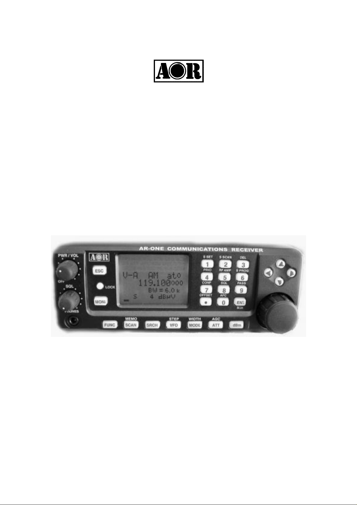
AR-ONE
Ultra Wide Band
Communications Receiver
Operating manual
AOR, LTD.
Page 2

1
Table of contents
1 Introduction
4
1-1 Introduction ----------------------------------------------------------------
4
1-2 Take care of your radio ----------------------------------------------------------------
5
1-3 Attention while operating ---------------------------------------------------------------
6
1-4 Accessories supplied ---------------------------------------------------------------
8
1-5 Controls and functions -------------------------------------------------------------- 9
1-5-1 Keypad --------------------------------------------------------------
11
1-5-2 Summary of keys -------------------------------------------------------------
11
1-6 Computer control -------------------------------------------------------------
---------------------------------------------------------------
14
1-7 IF output and Spectrum Display Unit (SDU5500, SDU5600) --------------------- 14
2 Getting Started
14
2-1 Making the AR-ONE ready for operation -----------------------------------------------
14
2-1-1 LCD -------------------------------------------------------------
14
2-1-2 Connect the antenna ------------------------------------------------------------
14
2-1-3 Connect power -------------------------------------------------------------
15
2-2 Switching on for the first time ------------------------------------------------------------ 15
2-3 Squelch Circuit -------------------------------------------------------------
15
2-4 VFO selection -------------------------------------------------------------
16
-------------------------------------------------------------
2-4-1 Tuning frequency ------------------------------------------------------------
16
Page 3

2
2-4-1-1 Entering frequency using the numeric keypad ----------------------------
16
2-4-1-2 Changing frequency using the main tuning dial ---------------------------
16
2-4-1-3 Changing frequency using UP arrow key or DOWN arrow key ---------
17
2-5 Changing receive mode --------------------------------------------------------------
17
2-5-1 Auto mode selection -------------------------------------------------------------
19
2-5-2 Receive mode selection -------------------------------------------------------------
20
2-6 Changing tuning step size -------------------------------------------------------------
20
2-7 IF bandwidth -------------------------------------------------------------
21
2-7-1 Manually selecting IF band width --------------------------------------------------- 22
2-8 AGC (Automatic Gain Control) ------------------------------------------------------------ 22
2-9 ATT (Attenuator) -------------------------------------------------------------
23
2-10 RF Amplifier -------------------------------------------------------------
24
2-11 OFFSET -------------------------------------------------------------
25
2-11-1 Using pre-programmed frequency offset data ----------------------------------
25
2-11-2 Entering new frequency offset data ------------------------------------------------
26
3 Memory channels and banks ---------------------------------------------------------------- 27
3-1 Memory channel overview ---------------------------------------------------------------- 27
3-2 Storing VFO frequency and data into memory ---------------------------------------- 28
3-3 Memory read “M.RD” --------------------------------------------------------------- 30
3-4 Deleting memory channels --------------------------------------------------------------- 31
4 SCAN – scanning memory channels ------------------------------------------------------- 31
4-1 SCAN – outline introduction -------------------------------------------------------------- 31
4-2 Starting SCAN --------------------------------------------------------------
Page 4

3
32
4-3 Selecting a SCAN bank -------------------------------------------------------------- 32
4-4 Select SCAN -------------------------------------------------------------
32
4-4-1 Adding select scan channels in memory read ------------------------------------ 32
4-4-2 Starting/Stopping select scan --------------------------------------------------------- 33
5 Search mode -------------------------------------------------------------
34
5-1 Search type -------------------------------------------------------------
34
5-1-1 Program search overview ------------------------------------------------------------- 34
5-2 Starting Program search ------------------------------------------------------------- 34
5-2-1 Reversing the direction of search --------------------------------------------------- 35
5-2-2 Forcing the search to resume ------------------------------------------------------- 35
5-2-3 Stopping the search ------------------------------------------------------------
36
5-3 Selection of search bank ------------------------------------------------------------
36
5-4 Programming a search bank ----------------------------------------------------------- 36
5-5 Deleting search banks ------------------------------------------------------------
41
5-6 Locking out unwanted active frequencies (PASS) ------------------------------------- 43
5-6-1 Deleting pass channels -------------------------------------------------------------
43
6 Configuration menu ------------------------------------------------------------
45
6-1 Configure beep ------------------------------------------------------------
45
6-2 Configure lamp ------------------------------------------------------------
46
6-3 Configure dimmer ------------------------------------------------------------
47
6-4 Configure contrast -----------------------------------------------------------
48
6-5 Configure manual AGC ----------------------------------------------------------
48
Page 5

4
6-6 Configure IF-GAIN (Intermediate Frequency gain) ---------------------------------- 49
6-7 Configure RF-GAIN (Radio Frequency gain) ------------------------------------------ 50
6-8 Configure Remote BPS (Baud Rate) ---------------------------------------------------
50
6-9 Configure RMT-ID (Remote ID) ----------------------------------------------------------- 51
6-10 Configure DELAY (Scan delay and Search delay) --------------------------------- 52
6-11 FREE (Scan free and Search free) ----------------------------------------------------- 53
6-12 Configure SPEAKER -----------------------------------------------------------
53
6-12-1 Configure rear speaker -----------------------------------------------------------
53
6-12-2 Configure front speaker ---------------------------------------------------------- 54
6-12-3 Configure headphones output ------------------------------------------------------ 55
6-13 Configure audio filters (HPF/LPF) ------------------------------------------------------ 55
6-13-1 Configure audio HPF (High Pass Filter) ----------------------------------------- 55
6-13-2 Configure audio LPF (Low Pass Filter) -----------------------------------------
56
6-14 Configure Audio De-emphasis ----------------------------------------------------------
57
6-15 Configure PRIO-CH (Priority Channel) -----------------------------------------------
58
6-15-1 Engaging PRIO channel ---------------------------------------------------------
58
6-16 Configure IF output frequency ---------------------------------------------------------
59
6-16-1 Selecting IF output frequency --------------------------------------------------------
59
6-17 Configure reference signal source --------------------------------------------------------
60
7 Computer control -------------------------------------------------------
61
7-1 How to send an RS-232C command -------------------------------------------------------
61
7-2 Power on the AR-ONE ------------------------------------------------------
61
7-3 Detailed RS-232C Command Listing of the AR-ONE ----------------------------------
Page 6

5
62
8 Specifications ------------------------------------------------------
75
9 Optional Accessories -----------------------------------------------------
76
10 Limited Warranty ------------------------------------------------------
77
1 Introduction
1-1 Introduction
Thank you for purchasing t he AR-ONE Ultra Wide Band Communicat ions receiver .
The AR-ONE is designed using the very latest technology to ensure the highest levels
of
performance and reliabil it y. To get the best possible results from your AR-ONE, w e
strongly recommend you to read this manual and familiarize yourself with t he receiver.
Although carefully designed, this receiver (like all receivers) suffers from a degree of
internal noises known as spuri ous emission. They are a product of the receiver’s
circuitry, and therefore, it does not represent a fault. Apparent faults may be due to
accidental misoperation of t he receiver. If you believe there is a problem, carefully read
Page 7
6
all of the manual before d eciding to contact your dealer for advice.
It is acknowledged that sect ions of this manual are repetitive, this is to enable the
manual to be used as a reference book (you don’t have to read it all from cov er t o cover
in one go). Due to the internat ional nature of the product, some graphics contain
Japanese characters.
Every effort has been made to make this manual correct and up to date. Due to
continuous developme nt of t he receiver. and by error or omission anomalies may be
found and this is acknowl edged.
© This manual is prote ct ed by copyright AOR, LTD. 2003. No information cont ained in
this manual may be copied or transferred by any means without the prior written
consent
of AOR, LTD. AOR and the AOR logo are trademarks of AOR, LTD. All other
trademarks
and names are acknowledged.
Main features:
z
Super wide coverage: 10 KHz ~ 3. 3 G Hz (cont inuous)
z
1,000 memory channels
z
10 VFOs
z
Monitor AM, NFM, WFM, USB, LSB, CW, Data
z
Ultra-stable reference frequency oscillator
z
Two RS-232C ports plus control head port
z
Control up to 99 AR-ON E Units with one PC
z
Triple conv ersion superheterodyne front end
z
Antenna input level readout
z
Adjustable BFO
z
High intercept
z
IF signal output (10.7 MHz or 455KHz)
z
Excellent sensitivity
z
Detachable control h ead (optional kit required)
Page 8

7
1-2 Take care of your radio
There are no internal operator adjustments. In the unlikely event of servicing being
required, please contact y our dealer for technical assistance.
Do not use or leave the receiver in direct sunlight (especially the LCD). It is best to avoid
locations where excessive heat, humidity, dust and vibration are expected. Always
keep
the AR-ONE free from dust and moisture. Use a soft, dry cloth to gently wipe the set
clean, never use abrasive cleaners or organic solvents which may damage certain
parts.
Treat the AR-ONE with care, avoid spillage or lea kage of liquids into the receiver and
associated power supply. Special care should be taken to avoid liquid entering around
the controls, through the speaker grille or via the connection jacks.
The AR-ONE is designed for operation from a good quality regulated DC supply of 12
to
14 V, which should be capabl e of supplying 1.5 amps. Never connect the AR-ONE
directly to the AC outlet.
The DC input jack is conf i gured Center Positive, the chassis of the rece iver is at
negative ground. Where p r ovided (depending upon world market location), the power
supply is pre-wired and prov ides a nominal 12 V DC output with suitabl e connectors
being fitted as standard for the AC power input and connection to t he A R-O N E.
SAFETY NOTICE – Always disconnect the power supply from the AC outlet when
not in use. If used m obi le, it should be noted th at the AR-ONE has NOT been
manufactured or tested to meet any speci fi c mobile safety requirements.
The AR-ONE has no internally user adjustable parts.
If using the AR-ONE in a base st at ion situation, the best short wave reception is usually
achieved by the fitting of a separate external earth rod, however, consider the
implications carefully if your AC building supp ly uses a Protective Multiple E a rth (PME)
system. If in doubt consult an expert electrician. Never earth to a gas pipe!
The AR-ONE has a single N t ype antenna connector for all frequen cies. This is intended
for connection to a 50 ohm (unbalanced) coaxial fed antenna such as a discone, dipole,
Page 9

8
unipole, Yagi, etc. When sighting the antenna, avoid pow er cables. Ensure that you do
not confuse the antenna and ot her I F out put connectors as they are closely locat ed.
Operating anomalies
Should the AR-ONE appe ar t o behave strangely, normal operation may be ea sily
achieved by resetting the microprocessor. Two scenarios may be encountered due to
power transients etc:
1. Symptom: LCD remains on, no control of the keypad.
Action: Remove any connection to external power and leave it for
approximately 30 seconds. Reconnect power and switch on again.
Normal operation should be restored but the last used frequency will be lost, the
AR-ONE will restore the last but one frequency to
display.
2. Symptom: The AR-ONE fails to power up.
Action: Try the suggestions given in (1) then hold the ESC key while
powering up the AR-ONE to ‘Soft reset’ the microprocessor.
1-3 Attention while operating
1. Certain key operation are acted upon when the key is RELEASED, not w hi le it
is pressed. Allow time for t he AR-ONE to register such actions before pressing
another key.
2. The keylock (LOCK) is intentionally made to be difficult to operate to prevent
accidental operation. To release keylock, t he LOCK key has to be held for more
than one second, the key icon on the LCD confirms operation. The LOCK is
disabled during keying seque nces (such as when entering frequencies).
3. If a key sequence is not completed, the microprocessor will automatically
abort
most operations after about 90 seconds of keypad inactivity.
4. Currently displayed VFO dat a is saved at power down (to increase speed o f
operation and to reduce writ e cycles). For this reason, if the AR-ON E is powered
down using the PWR/VOL control or external power is removed, t he last
displayed frequency w ill be lost and the frequency used prior to this will be
displayed when next powered up.
Terminology – Search & Scan
Page 10

9
If you have not used a wide band receiver before or not familiar with the terminology used,
it
is very important to understand the difference between SEARCH and SCAN modes.
SEARCH: The AR-ONE provides several operations where transmissions (active
frequencies) may be automatically located by sweeping the receiv er over a wide
frequency range, either fr om the currently displayed frequency t r aveling upwards
(or downwards) in a specified tuning increment (step) or by sweeping
over-and-over between two specif ied frequency limits. This proces s is known as
SEARCHING, as t he little implies, it can take a long time to find transmissions due
to their ‘often intermittent’ and brief nature. For this reason it is best to slice large
frequency ranges into small er, more manageable pieces where they may be
intensively studied.
When examining large frequency bands, it is common to find t hat 90% of
frequencies are inactive and only a small number of t he rema ining constitute what
you really want. Searching still remains the best way to initially locate active and
interesting transmissions (in conjunction with a good frequency listing and band
plan).
SCAN: Once active tr ansmission have been identified (either by searching or by
using a good frequency guide), it is more efficient to store the dat a int o memories
which can be rapidly and automatically monitored in succession stopping whe n
activity is encountered. Th is f orms a much more efficient means of mon it ori ng the
most wanted frequencies as you have targeted 100% what you most want t o hear,
by contrast searching is very inefficient for say-to-day monitoring.
: It is very important that the squelch is advanced to cancel background
Note
noise for the search & scan fu nctions to operate. This is because the
AR-ONE believes that it has found a n active frequency when the squelch
opens and “S” ‘squel ch open’ icon is displayed to the left of the signal meter.
Advance the squelch control clockwise until the backgr ound noise is just
cancelled, this is known as the threshold position. If the squelch control is
advanced too far, weaker signals may be missed .
No noise and no “S” icon displayed (with squelch advanced clockwise
Page 11

10
passed threshold) = squelch cl osed.
Signal received or ‘noise’ emanating from speaker (squelch fully
counterclockwise, below thresho ld) with “ S” icon displayed = squelch open.
1-4 Accessories supplied
The following items are provided in the carton box:
1 AR-ONE receiver
1 AC power supply (may be supplied in some world market areas and in a separate
carton)
1 DC power cable
1 Operating manual (this booklet)
1-5 Controls & functions
Controls are located on th e front with most connectors on the rear of the AR-ONE, a brief
identification is given here:
Page 12
11
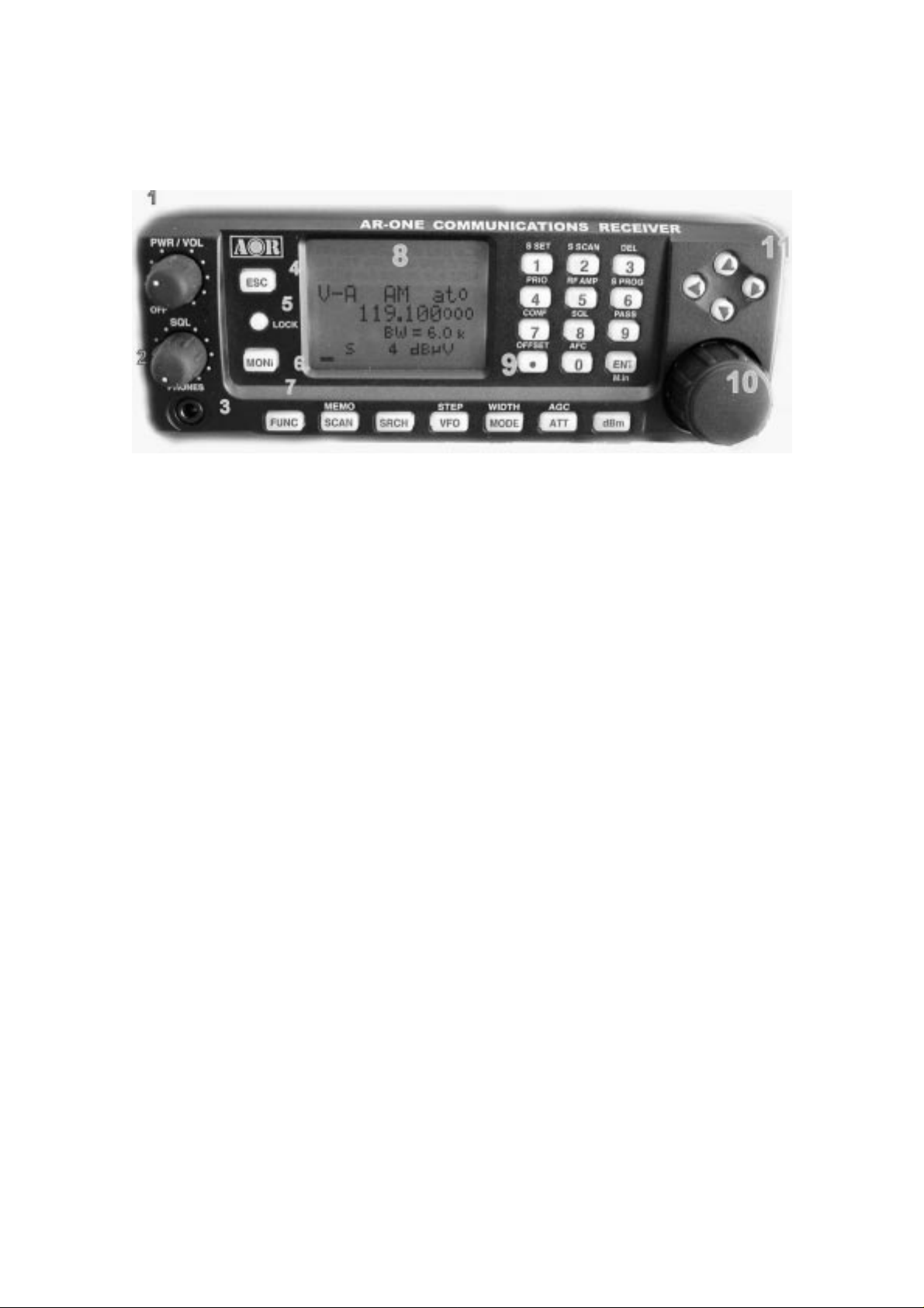
Front Panel
1. Volu me co nt rol plus isolate power On/Off
2. Squelch control
3. Phones jack (3.5 mm mono or stereo may be used)
4. Escape key
5. Key Lock key
6. Monitor key
7. Function key
8. LCD (Liquid Cryst a l Display)
9. Main keyboard (ten keys plus decimal and enter)
10. Main tuning dial (frequency change and menu manipulation)
11. Arrow keys (frequency change and menu manipulation)
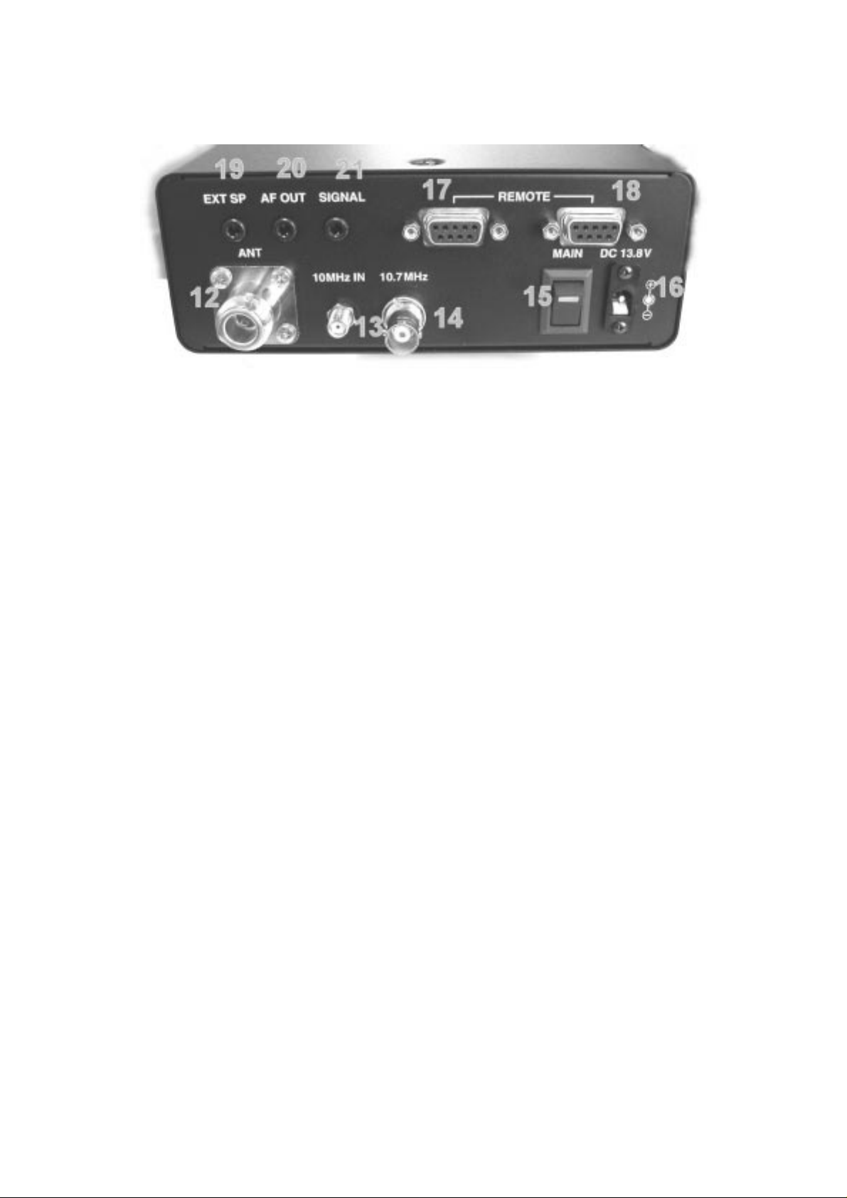
Rear Panel
Page 13
12
12. Antenna connector (N type)
13. Standard signal (10 MHz) input connector
14. IF output connector
15. Main power switch
16. DC power input connector
17. Remote control connector (RS-232C) -- 1
18. Remote control connector (RS-232C) – 2
19. External signal output connector (when used, t he internal speaker is disabled.)
20. Audio output connector (speaker output without disabling the internal
speaker.)
21. Signal output connector (0 – 4.5 V DC maximum)
RS-232C connecti on requirements:
The REMOTE RS-232C connector (16 & 17 above) is designed for connection directly to
an
RS-232C serial port of a PC. By daisy chain of the units, you can cont rol up to 99 AR-ONE
with one PC. No interface is requ ired, just a standard RS-232C straight cab le. Connections
for a PC are as follows:
AR-ONE DB-9 RS-232C cable DB-25 RS-232C cable
Pin # 2 Pin # 2 Pin # 3
Pin # 3 Pin # 3 Pin # 2
Pin # 5 Pin # 5 (Ground) Pin # 7 (Ground)
Pin # 7 Pin # 7 Pin # 4
Pin # 8 Pin # 8 Pin # 5
Page 14

13
1-5-1 Keypad
Keypad conventions
Most keys have secondary functions , their functions are printed on the panel. However,
due
the restriction of availabl e size, not all functions can be shown on t he keypad printing.
For the secondary functio ns of t he AR-ONE, they are indicated w ith w hite characters above
each key. T o access t he secondary function, push the FUNC key, and then push the
respective key.
1-5-2 Summary of keys
ESC
Push this key to cancel ent ry from the keypad.
LOCK
This key is intentio nally small to reduce the chances of accidental operation. Key lock is
useful when you do not wish an i m port ant frequency to be lost or the AR-ONE to be
incorrectly set to a diff erent frequency.
MON
The monitor key is used to force the squelch open so that you may manua l ly intervene to
ensure that no weak signals are missed.
FUNC
The function key is used to select the secondary function of keypad.
SCAN
Push this key to initiate SCAN.
MEMO
Push the [FUNC] key, and then push this key to go into the me mory read mode.
SRCH (SEARCH)
Push this key to initiate SEARCH.
Page 15

14
VFO
Push this key to select
AR-ONE.
VFO
mode. There are 10
STEP
Push the
MODE
Push this key to select the desired receive mode.
[FUNC]
key, and then push to select the desired frequency step.
WIDTH
Push the
menu.
[FUNC]
key, and then push this key to select t he desired IF band width selection
ATT
Push this key to activate the
parameter. The
AUTO
RF ATT
selection will work best for most of cases.
(Attenuator). Move the cursor to select the desired
VFO
VFO-A
s (
through
VFO-J
) with the
AGC
Push this key to select the
Move the cursor to select the desired
MEDIUM
CW,
desired parameter (betwe en 0 – 255) can be selected for manual gain co nt rol.
for AM and FM, and
AGC
(Automatic Gain Control) time constant of the receiver.
AGC
SLOW
time constant. Usually,
for SSB mode. When
FAST
MANU
is used to receive
is selected, any
dBm
Push this key to toggle a unit of the incoming signal strength in betwe en
ordinary S unit.
dBm, dBuV,
0 ~ 9 , .
Numeric key
S. SET
Push the
scan
in the
[FUNC]
SELECT SCAN
key, and then push this key to select the desired memory channels to
mode.
or
Page 16

15
S.SCAN
Push the
[FUNC]
key, and then push this key to initi a t e
DEL
Push the
and pass frequency.
PRIO
Push the
[FUNC]
[FUNC]
key, and then push this key to delete t he me mory channel, search bank,
key, and then push this key to initi a t e
RF AMP
Push the
function (
[FUNC]
ON/OFF/AUTO
key, and then push this key to activ at e/ deactivate the
S PROG
Push the
[FUNC]
key, and then push this key to set the search bank.
CONF
).
SELECT SCAN
PRIORITY CHANNEL RECEIVE
.
RF amplifier
.
Push the
setting beep sound, backlit function, etc.
[FUNC]
key, and then push this key to access
SQL
Push the
level squelch mode.
[FUNC]
key, and then push this key to select eit her t he noise squelch mode or
PASS
Push the
mode.
[FUNC]
key, and then push this key to set the pass frequency in the search
OFFSET
Push the
the duplex mode.
[FUNC]
key, and then push this key to activ at e/ deactivate the frequency offset i n
AFC
Push the
[FUNC]
key, and then push this key to activ at e/ deactivate the
CONFIGURATION
AFC
mode such as
(Automatic
Frequency Control) funct i on.
Page 17

16
ENT
Push this key to accept da ta entry .
M. in
In the manual receive mode or search mode, push the
to enter the frequency into memory.
[FUNC]
key, and then push this key
1-6 Computer control
Connect the AR-ONE to the serial port of a computer using an RS-232C serial cable
terminated in a 9-pin male connector. The RS-232C parameters may be defined using the
CONFIG
two independent RS-232C port with the AR-ONE, it is possible t o set an ‘ address’ to
facilitate connection of up to 99 AR-ONE to a single PC.
The RS-232C parameters are as follows:
menu. Baud rates (transfer speed) set t o ei t her 4800 or 9600 bps. Since there are
Baud Rate: 4800 or 9600 bps
De-limiter: CR, LF
Data bit: 8 bit
Stop bit: 2 bit
Parity: None
X parameter: ON
1-7 IF output and Spectrum Display Unit (SDU5500, SDU5600 )
The rear panel has a 10.7 MHz I F out put designed to drive the optional SDU5 500 or
SDU5600 Spectrum Disp lay Unit. The SDU5500 or SDU560 0 provides an excellent tool for
locating elusive tr ansmission with a PEAK capability to ‘freeze’ the briefest of transmissions
for later measurement of fr equency and level after the event.
(Note: The IF output frequ ency is selectable in the
CONFIG
menu. (10.7 MHz or 455KHz ) .
2 Getting started
2-1 Making the AR-ONE ready for operation
2-1-1 LCD (Liquid Crystal Display)
All relevant operational information is provided via the LCD. The LCD contrast is
adjustable.
Page 18

17
2-1-2 Connect the antenna
For reception on the all bands, connect the antenna to the N connector on the rear panel of
the AR-ONE. An option al SA7000 Super Wideband Receiver is provided for this purpose.
A receive frequency range of the SA7000 is 30 KHz ~ 2000 MHz.
2-1-3 Connect power
Connect the power to the DC pow er j ack on the rear panel of the AR-ONE. Use either a
supplied AC power adapter. Or a regulated DC power supply (12 ~ 14 V with capacity 2A)
may be used. Do not connect t o a 24 V system.
Main Power Switch ___| |___ DC Power Jack
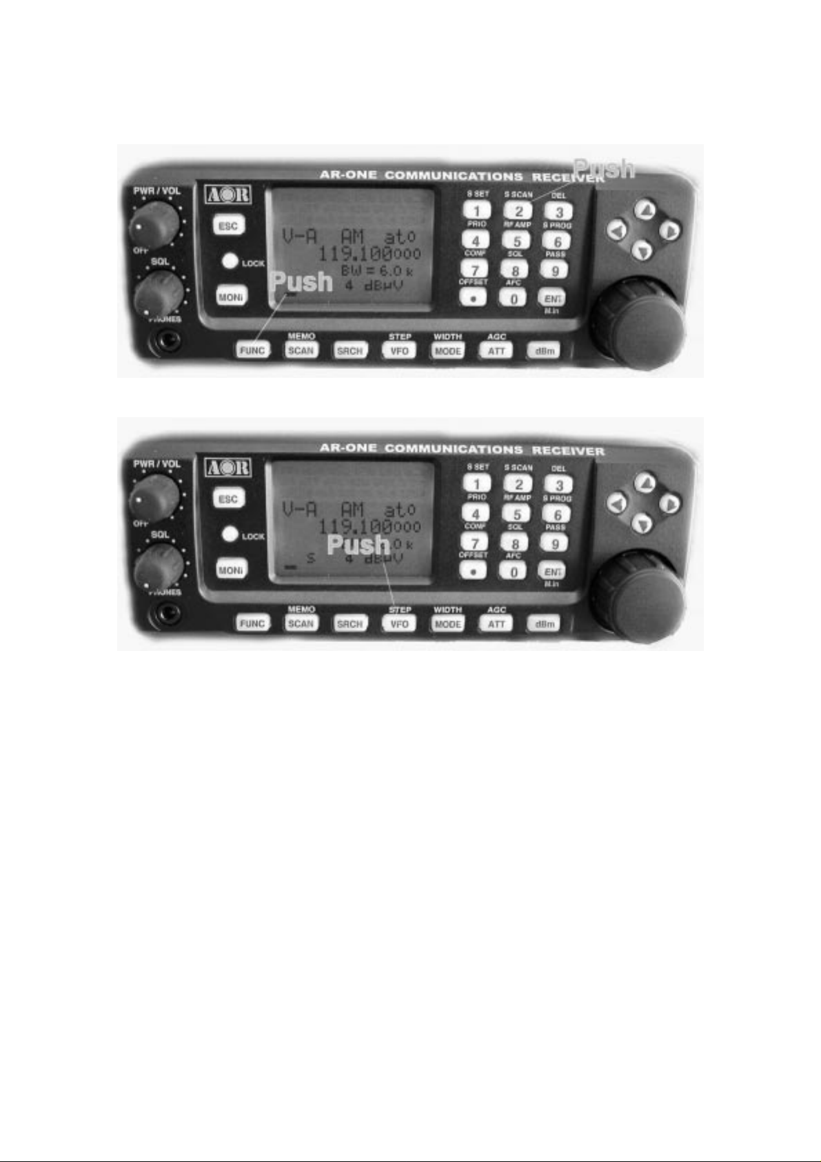
2-2 Switching On for the first time
Set the squelch control to t he ‘ mid point’ . Turn the power sw itch on the rear panel of the
AR-ONE. This is a main power switch. The Green LED lit on the switch. Then rotate the
PWR/VOL control to the ‘ m id point’, as you start to rotate the PWR/VOL control, a ‘click’ w ill
be heard as the power isolation switch contact switches on. Please be careful NOT to
switch
on any receiver with an earphone connected, there may be an audible cl ick when the unit is
switched on or the volume may be accidentally set too high.
Power/VOL control
•
•
Squelch cont r ol
The AR-ONE will take approximately 1 - 2 seconds before the information appears on the
Page 19

18
LCD. It is normal, for the micropr ocessor of the AR-ONE generates the ‘boot up data’
required to control the receiver.
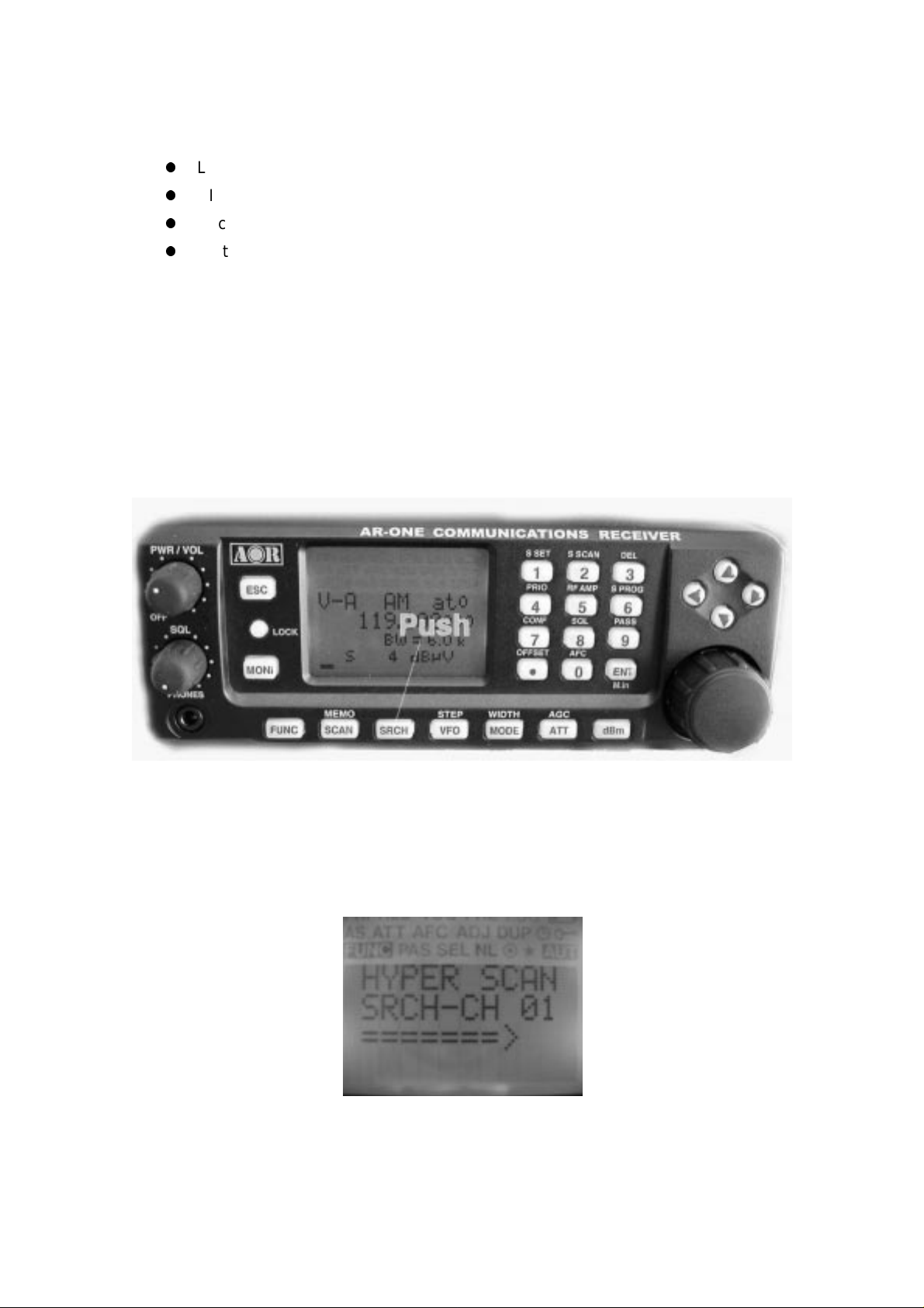
2-3 Squelch Circuit
In normal use,
search and scan operations. The
check the signal strength of
above a preset level (which is programmable).
To select
NOISE SQUELCH
LEVEL SQUELC H
1. Push the
FUNC
is used. However,
LEVEL SQUELCH
active
frequencies and to only st op when the signal strength is
, perform the following steps:
key.
LEVEL SQUEL CH
parameter causes the AR-ONE to
can be selected for
2. Push the “8” key.
3. On the bottom of the LCD, a bar will be displayed. Using the
adjust the desired signal level.
4. Push the
5. Squelch will open only when the input signal strength is ab ove this set level.
6. To select
ENT
key to confirm entry.
NOISE SQUEL CH
, repeat above steps.
SQL
control,
2-4 VFO selection
The AR-ONE has ten (10) VFOs being identified as “V-A” through “V-J” on the top left of
the
LCD. The term VFO historically means
to
a tuneable data store which cont ains frequency, step, step-adjust, attenuator etc. Pushing
VFO
the
AUTOMODE setti ng, and therefore, in most cases a proper receive mode and frequency
key each time will select the one VFO out of 10. The AR-ONE has an
‘Variable Frequency Oscilla tor’
and today refers
Page 20

19
step are automatically sel ect ed.
2-4-1 Tuning frequency
2-4-1-1 Entering a frequency usi ng the numeric keypad
While in VFO mode, enter the required frequency using MHz format followed by the ENT
key.
Example of frequency entry of 80. 8 MHz
Push the [8] key. Push the [0] key. Push the [.] key. Push the [8] key. Push the [ENT] key.
Example of frequency entry of 954 KHz (0.954 MHz)
Push the [.] key. Push the [9] key. Push the [5] key. Push the [4] key. Push the [ENT] key.
Aborting frequ ency input
If for some reason you do not wish to co mp let e t he frequency data input, push t he ESC key
before completing the input sequence with the ENT key.
2-4-1-2 Changing fr equency using the main tuning dial
While in VFO mode, the active VFO frequency may be ‘tuned’ in using the rotary main
tuning
dial which is mounted on the right side of the front panel. You may rotate the dial ‘clockwise’
to increase frequency or t urn ‘counterclockwise’ to decrease frequ ency.
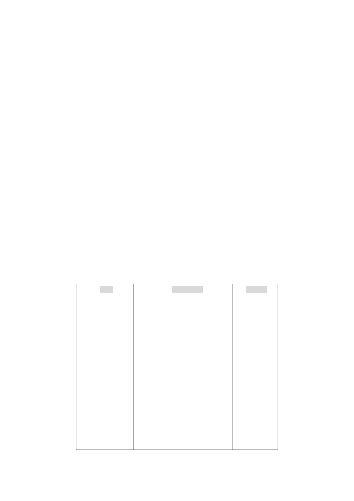
2-4-1-3 Changing fr equency using UP arrow key or DOWN arrow key
The UP arrow key and DOWN arrow key provide a convenient method of frequency
change.
Page 21

20
The speed at which the receiv er st eps up or down depends upon the STEP SIZE which is
default to AUTO. In AUTO the step size, receiver mode etc. is taken from the factory
pre-programmed band plan but may be ov erridden at any time.
Push the UP arrow key to tune the receiver upward in whichever step size is selected, use
the DOWN arrow key t o t une t he receiver downward in frequency.
2-5 Changing receive mode
Due to the necessities of signal bandwidth, channel occupancy and transmission efficiency.
Different receive modes are used by various services. I n addit ion to this specification for
tuning step and receive mode are allocated by departments of Govern ments following
international discuss ions so are not consistent throughout t he w orl d. For this reason, it is
necessary to change receiv e mode in order t o monitor various transmissions.
For your convenience, receive mode and tuning step size have been pre-prog rammed i nto
the AR-ONE auto-mode b and plan data at the factory to simplify operat ion of the receiver,
especially while you familiarize yourself with all functions. Should you wish, the defaults
may
be manually overridden at anytime so that you may select an alternat ive receive mode and
tuning step on any frequency.
AM
Amplitude Modulation – U sed by broadcast services throughout the world on long wave,
medium wave and shortwave. AM is also used by VHF airband, UHF mi litary airband and
some PMR (Private Mobil e Radio) and utility services.
FM
There are two common types of FM (Frequency Modulation, these are:
NFM – Narrow Band Frequency Modulation – this provides high quality communication for
relatively short distance operation. FM uses a greater frequency bandwidth than other
modes such as SSM so is less efficient.
NFM is the most common mode used above 30 MHz with the exception of the airbands.
NFM is widely used on the VH F bands: VHF marine band, 2m amateur ba nd, 70 cm
amateur band, PMR (Priv at e Mobi le Radio) and utilities.
Page 22

21
In the absence of signal, the background white noise may appear quite loud. For ease of
listening, the squelch control should be rotated clockwise until he background noise just
disappears, this should be carried out while no signal is present. The point where the
background noise is cancelled is known as threshold point. Do not advance the squelch
control more than necessary or the receiver will appear to be desensitized and weaker
signals will be missed.
WFM – Wide Band Frequency Modulation – used by VHF and UHF broadcast stations as
excellent audio quality is available due to the relatively wide frequency bandwidth
employed.
Used only for local services such as VHF band stereo (received as mono on the AR-ONE)
and UHF TV sound channels.
LSB – Lower Side Band – is form of SSB (Single Side Band). LSB t ends not to be used
commercially but is extensively used by Radio Amateurs on frequencies below 10 MHz.
This assists the separatio n of Commercial and Amateur users on trad it ionally shared bands
and prevents them from speaking to each other .
SSB is a very efficient method of transmission as the unwanted second sideband and
carrier
have been removed. This allow s t he f ull transmitter power to be employed in c arrying
useful information within the wanted sideband. As a result, greater distances are possible
on
SSB and a smaller frequency bandwidth is required than most other modes.
USB – Upper Side Band – The same comments apply as for LSB. By convention, Radio
Amateurs also use USB above 10 MHz.
CW - Continuous Wave – Often referred as Carrier Wave or Morse Code. Commonly
used
on the short wave bands by radio a mateurs toward the lower end of each band all ocation.
Some commercial use is still made by shipping etc although its use is being phased out
due
to the introduction of automated stations.
2-5-1 Auto-mode selection
Page 23

22
When auto-mode is in operation, receive mode and tuning step s iz e are automatically
selected for you by the AR-ON E microprocessor .
To activate auto-mode or reconfirm its selection w hi l e in VFO mode,
Push and hold the MODE key for more than 2 seconds.
The AUT icon appears on the top right portion of the LCD.
Note: Auto-mode is cancelled as soon as the receive mode, tuning step or other related
data
is changed. Remember th at aut o-STEP and auto-MODE are linked, reselect AUTO-MODE
if either have been adjust ed and you require the auto bandplan select ion.
2-5-2 Receive mode selection
Any receive mode may be selected at any frequency within the receiver’s frequency
coverage. To access the receive mode menu, push MODE, the following modes are
available: AUT O , WFM, NFM, USB, LSB, CW. Use the main tuning dial or arrow key to
make selection. To accept the selection, push the ENT key.
2-6 Changing tuning STEP size
The specification for channel occupancy, step (separation) and mode are decided by and
allocated by departments of G overnments following internat ional discussions.
Not surprisingly the allo cation of frequency bands are not the same all over the world and
channel separation (st ep) varies from band to band. As an example, the channel separation
(step) for the MW (medium wave) band in the U.S.A. is 10 KHz while in Europe and Japan
they are 9 KHz.
Page 24
23
For above reasons it is necessary t o alt er the STEP size according to local bandplan
conventions. The AR-ON E has been pre-programmed at the factory w ith al l the bandplan
data (specific to each market area) so that the AR-ONE will automatically select the
appropriate step size and mo de f or t he frequency chosen. This greatly si mp li f ies operation
of the receiver while y ou are familiarizing yourself with all functions.
The pre-programming of step size may be manually over-ridden so you may choose
alternative settings at wi ll or when band plan are updated.
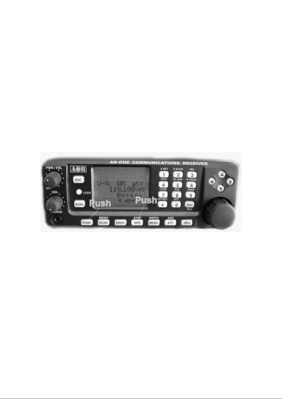
Should you wish to chang e t he def ault tuning step size, push the FUNC key and then push
the VFO key.
The third row of the LC D will display the current default size.
The bottom line of the LC D displays the icon “STEP SET” to indicate that the AR-ONE is
waiting you to change the step size.
Use the main tuning dial or arrow key to select the desired step size. To accept the
displayed
tuning step size, push the ENT key.
The tuning step size may also programmed in 1 Hz (via the keypad) so that unusual step
sizes other than stated are possible. The acceptable step size range is less than 1 MHz in
1
Hz steps.
2-7 IF Bandwidth
The IF bandwidth select s how SELECTIVE the receiver will be when monitoring signals off
Page 25

24
air. However, it is not simply a case of using the narrowest filter at all times, particular
modes
require differin g amounts of bandwidth in order to operate otherw ise the receive system
simply will not produce intelligible sound.
Correct receive mode and I F bandw i dt h must always be selected for optimu m recept ion. If
the bandwidth selection is too narrow, distortion or signal break-up may occur. If the
bandwidth selection is t oo wide, adjacent interference may be encountered.
For this reason, a selection of IF filter bandwidths are fitted as standard. Typical examples
of
receive mode and IF bandw idth are:
300 KHz -- VHF FM broadcast (220 KHz may be also be used – mono only)
200 KHz -- VHF FM broadcast (110 KHz may be also be used – mono only)
100 KHz or 30 KHz – Wireless mic, etc. (30 KHz for satellite FAX, too)
16 KHz – PMR, amateur band, etc. FM 6 KHz may also be used
8.5 KHz or 6 KHz – VHF/UHF a irband, short wave broadcast, medium & long w ave, PMR,
etc.
3 KHz – Short wave amateur band, short wave utility such as ocea nic airband etc.
0.5 KHz – Morse code used by radio amateurs and some marine traf fi c on short wave
An appropriate IF filter is aut omatically selected when auto mo de i s engaged. However any
combination of IF filter a nd receive mode is possible in the manual mode. When you have
manually selecte d an I F f il ter bandwidth, automode will be disengaged, but the receive
mode, step size, et c w ill be retained until they are chang ed manually.
2-7-1 Manually selecting I F bandwidth
Push the FUNC key, and then push the MODE key.
Selecting a new bandwidth from the list of 300, 200, 100, 30, 16, 8.5, 6, 3, and 0.5 KHz by
rotating the main tuning di al or arrow key . To accept the new bandwidth selection, push the
ENT key.
Page 26
25
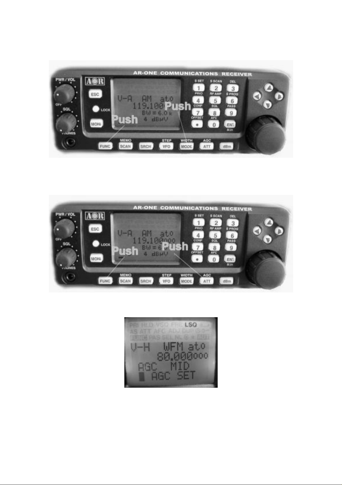
2-8 AGC (Automatic Gain Control)
To change the
Selecting a new
main tuning dial or arrow key. To accept the new
AGC
parameter setting, push the
AGC
parameter from the list of
FUNC
key and then push the
MANU, FAST, MID, SLOW
AGC
parameter, push the
ATT
key.
by rotating the
ENT
key.
When
Configuration Menu.
MANU
is selected, a desired par ameter can be entered between
2-9 ATTENUATOR
0 ~ 255
in the
Page 27

26
Activating attenuator reduces signal to the RF input stages of the AR-ONE to prevent
overloading due to conne ct ion t o an external antenna or when the receiver is used i n close
proximity to strong transmissions.
The AR-ONE has four settings for ATT (attenuator), 0 dB, 10dB, 20 dB, and AUTO.
To change the ATT parameter setting, push the ATT key.
Selecting a new ATT parameter from the list by rotating the main tuning dial or arrow key.
To
accept the new ATT parameter, push the ENT key.
When ATT is set to OFF, the ‘t0’ icon will display on the top right o f the LCD,
When ATT is set to 10 dB, the ‘t1’ icon will display on top right of the LCD,
When ATT is set to 20 dB, the ‘t2’ icon will display on top right of the LCD.
2-10 RF AMPLIFIER
The AR-ONE features a p r eamplifier. The LCD icon “a” is used to display the setting in use.
Page 28

27
To change the RF Amplifier setting, push the FUNC key and then push the 5 key.
Selecting a new AMP parameter from the list of ON, OFF, AUTO by rotating the main
tuning
dial or arrow key. To accept the new AMP parameter, push the ENT key.
2-11 OFFSET
This function enables rec eive frequency to be quickly SHI FTED by a predetermined values,
this makes it easy to track dupl ex-t ransmissions or check repeater inputs/out puts. Offset
frequencies may be factory pre-programmed into the auto-mode band pl an data for some
world market areas. Frequ ency offset may also be programme d manually.
The locations for frequency offset storage are numbered 00 to 47 with 00 acting as OFF,
this
makes 47 locations av ailable.
Frequency offset may be programmed into VFO, memory channel and search banks. It is
most convenient to set-up in VFO mode then save the data to specific me mor y channels
for quick recall at a later date. Frequency offset is primarily designed for memory channel
Page 29

28
use, it may appear rather long winged to t oggle on/off in VFO mode. H ow ever even when
programmed, frequency offset is in no way detrimental to normal operation.
The acceptable range of frequency offset is 0 MHz to 999. 999 MHz, of course if the of fset is
set to 0 MHz, the frequency will not change! Before the FREQUENCY OFFSET function
can
be used, it first needs to be configured (unless factory programmed for certain bands).
2-11 - 1 U s i ng pre-programmed frequency offset data
To access the frequency offset set-up menu, push the FUNC key, and then push the .
(decimal) key.
The third line will display DUPLEX followed by the current offset channel number.
Use the main tuning dial or arrow keys to review the offset locatio ns. The shift direction
can be changed by pushing the FUNC key. To accept the offset setti ng, push the ENT key.
2-11-2 Entering new frequency offset data
Assume that you are in VFO mode.
To access the frequency offset set-up menu, perform the following steps:
1. Push the FUNC key, and then push the . (decimal) key. The third line will display
DUPLEX followed by the current offset cha nnel number.
Use the main tuning dial or arrow keys to review the offset locatio ns.
2. Push down arrow key. The cursor will move down to the bottom line of the LCD.
3. Enter the desired offset in MHz format. The shift direction ca n be changed by pushing
the FUNC key.
Page 30

29
4. To accept the offset setting, push the ENT key.
3 Memory channels & banks
It is convenient to store commonly used frequencies into a memory cha nnel along with
mode etc, this saves havi ng t o key the data in over and over again. Memory read is v ery
straightforward and quic k w hen compared to retyping all data.
3-1 Memory channel overview
Think of memory channels as pages in a notebook each of which is numbered to identify it.
Data may be written to ea ch new page (memory channel) and each page may be
overwritten with new data, they can be used over and over again. The AR-O N E has 1,000
memory channels and a priority channel.
Each memory channel may hold:
z
One receive frequency
z
Receive mode
z
Tuning step
z
Frequency offset
z
Attenuator setting
z
Text comment of up to 12 characters
The alphanumeric comment may be used to ease identification at a later date and to
provide
text search function. The 1,000 me mory channels are divided into 10 banks, each having
100 channels. The memory banks are identified by the first BANK number 0, 1, 2, 3, 4, 5,
6.
7, 8 and 9 and the individual ch annels are numbered from 00 to 99.
Page 31

30
Examples are “000” for the first channel location in memory bank “0” and “099” for the last
memory channel in memory bank “0”.
“415” is the location: memory bank “4” chann el “15”.
The data contents of memory and search banks are held in a EEPROM so that no backup
battery is required for memory retention.
The stored data may be quic kly and easily recalled, changed or deleted using the memory
recall and delete functions.
Note:
When the receiver is switched O FF, all VFO data will be automatically st ored int o
EEPROM memory storage
.
3-2 Storing VFO frequencies & data into memory
The process to save a displayed VFO frequency to memory is as fol low s:
a) In VFO mode, select the required frequency, mode, attenuator etc
b) Push the FUNC key, and then push the ENT key to go to the memory write screen
c) Use the keypad, main tuning dial or arrow keys t o select the desired memory location
(BANK and CHANNEL)
d) Add a text co mment (opt i onal) or delete an existing comment
e) Push the ENT key to exit the menu and save the data to the specif ied memory
location
Let’s assume that y ou are going to store the frequency of 123.50 0 MHz into memory bank
Page 32

31
“3” location “25” (325) while in VFO mode with the text comment of “AIRBAND”.
If a mistake is made durin g programming, push the ESC key to abort entry and return to
VFO mode.
1) Start by selecting VFO mode then key in the frequency of 123.500 MHz, “mode and
step
size” are set to the default auto mode.
Push the VFO key to set the AR-ONE into VFO mode.
Push the 1 key.
Push the 2 key.
Push the 3 key.
Push the . (decimal) key.
Push the 5 key.
Push the ENT key.
2) Then push the FUNC key, and t hen push the ENT key to enter “memory input” mode.
Using the main tuning di al or arrow keys, enter 325 to store the frequen cy into the
location. (memory bank 3, channel number 25)
3) Push the down arrow key to add the text comment “AIRBAND”
Use the main tuning dial to select the text and t he arrow keys to move position of text
input.
A maximum of 12 characters may be added to each memory channel, it is
recommended that a minimu m of t hree (3) be used for efficient use of the text search
function ( a minimum of 2 characters are required for text search).
To erase the text comment, push the SET key twice.
Push the ENT key to complete.
Page 33
32
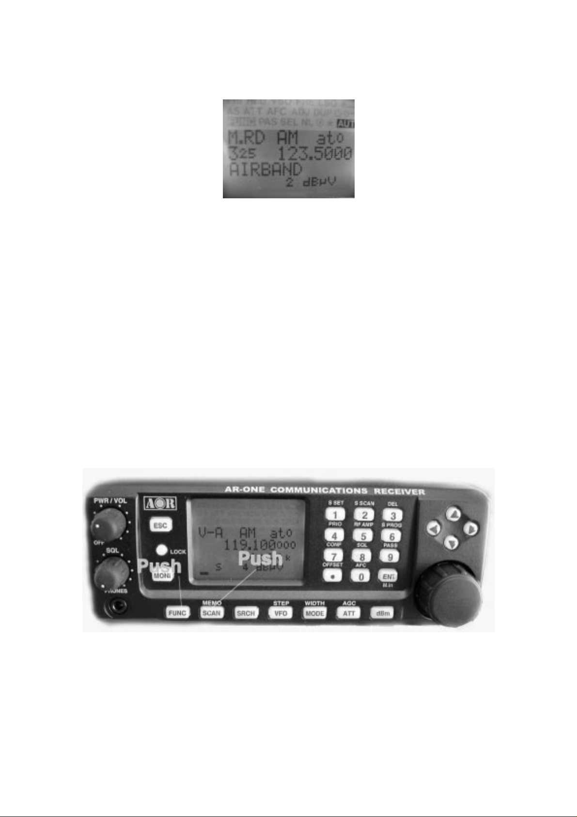
3-3 Memory read “M.RD”
Once frequency and mode data has been stored into a memory location, its retrieval is
quick
and simple.
Let’s assume that y ou are going to retrieve the frequency of 12 3. 500 MHz which has been
programmed into memory “325” during an earlier ex ampl e in t he preceding section of this
manual.
”
FUNC
key and the push the
Push the
M.RD
“
icon appears on the top left of the LCD to confirm operation. The AR-ONE will monitor
whatever memory channel you ent er memory read.
SCAN
key to go into
memory read mode
, the
The AR-ONE will display me mory channel, mode, text comment (if on e w as used). The
memory channel last used (for memory write or recall) will initially be d isplayed. If the
desired memory channel i s not i m med iat ely displayed, it may be recalled by key ing in t he
required three digit location.
Page 34

33
To recall memory channel “325”, push either the right arrow key or left arrow key to select
“3” as the memory bank. Rotate the main tuning dial or pushing either the up arrow key or
down arrow key to select “ 25”.
3-4 Deleting memory channels
It is possible to over-write a memory channel with new data or delete the chan nel entirely.
Push the FUNC key, and then push the 3 key to “MEM DELETE” menu.
Push either the right arrow key or left arrow key to select the desired memory bank.
Rotate the main tuning dial or pushing either the up arrow key or down arrow key to select
the desired memory channel t o delete.
Push the ENT key to delete it or push ESC to abort.
4 SCAN – scanning memory channels
The AR-ONE has a SCAN mode whereby the contents stored in the MEMORY
CHANNELS
ARE AUTOMATICALLY RECALLED AND MONITORED very quickly for activity –
scanned.
*** It is important that you do not confuse SCAN and SEARCH modes. ***
Page 35

34
SEARCH mode (covere d l ater in this manual) automatically TUNES THE RECEIVER
THROUGH ALL FREQUENCIES between two specifie d frequency limits looking for active
frequencies.
4-1 SCAN – outline introduction
During SCAN, the AR-ON E aut omatically recalls memory chan nel which contains data in
numeric order and monitors it looking for activity. When an ‘active’ memory channel is
located (when a signal is found and the squelch is open), the AR-ONE w i ll t emporarily stop
scanning.
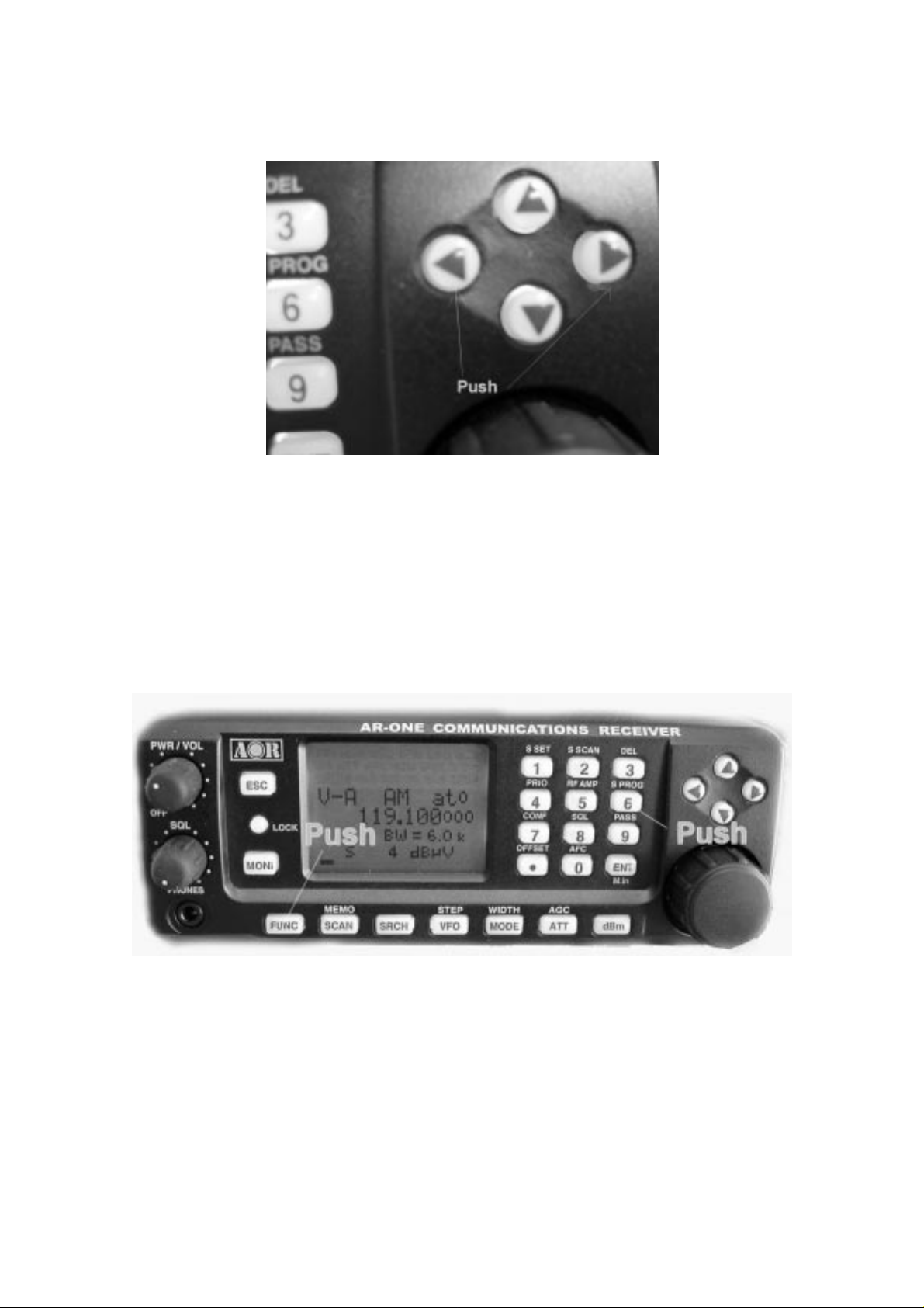
4-2 Starting SCAN
Presuming that some memory chan nels are programmed with data, to start the scan
process will take one push of the SCAN key.
The icon “HYPER CAN” is displayed on the LCD to indicate that the SCAN process has
been started, a bank number will be a lso b e displayed representing the current bank.
Ensure that the squ el c h is set to threshold point so t hat background noise is
cancelled and the squelch closes (otherwise scan will not operate).
When SCAN has been selected, only the currently displayed memory bank WHICH
CONTAINS DATA will be SCANNED, receive mode and frequency are unimport ant . Any
memory channels which cont ai n no dat a (empty) will be ignored (skipped).
4-3 Selecting a scan bank
The memory bank identifier (such as “3”) w il l be d isplayed on the middle right of the LCD.
If more than one memory channel is pro grammed into the current memory bank, and when
an ‘active’ channel ha s been located (busy, so the squelch opens), the scan process will
temporarily pause on the active channel, the memory location (such as “115”) will be
displayed along with any accompanying text (displayed underneat h t he memory location).
To select another memory bank for scanning, use the right arrow key or left arrow key .
If no data is available, t he next bank with valid data will be recalled (empty memory banks
are skipped).
Page 36
35
To exit from SCAN mode, push the VFO key.
4-4 Select scan
Select scan enables you t o ‘t ag’ memory channels to make a temporary list up to 50
channels in the same memory bank for scanning in a separate list called the SELECT
SCAN
LIST.
4-4-1 Adding select scan cha nnels in memory read
In memory read mode, push the FUNC key, and then push the 1 key to toggle the select
scan tag on/off, the icon “SEL” confirms selection.
4-4-2 Starting / stopping select sca n
To start select scan, you must first have at least two memory channels tagged for select
scan.
Push the FUNC key, and then push the 2 key to start s elect scan. The direction of s can can
be reversed using the main tunin g dial knob.
Page 37
36
To stop select scan, push the VFO key.
5 Search mode
In search mode, the AR-ONE is programmed to automatically tune between two specified
frequency limits looking for activity. Please refer to section 1-3 of thi s manual if you do not
fully understand the function of SEARCH.
5-1 Search type
The AR-ONE is equipped with PROGRAM SEARCH.
PROGRA M SEARCH = search between user preprogrammed limits
5-1-1 Program search overview
There are 40 program search banks (referre d to si mply as search banks) which can be
programmed with specific parameters:
Page 38
37
z
LO (lower) start frequency
z
HI (upper) stop frequency
z
Receive mode (or set to AUTO MODE)
z
Text comment
The program search banks are identi fi ed by numbers (01 ~ 40). To help with identification,
each bank may be labeled with an alphanumeric text comment.
5-2 Staring program search
Presuming that data is already stored into a search bank …
Push the
The LCD icon “
process will start fro m the lower frequency limit and will progress toward the u pper
frequency limit. When the program limit is reached, the search loops around and starts the
process again.
SRCH
key to start the program search process.
SRCH
” will be displayed and as long as the squelch is closed, the search
Note
: If no search banks have been programmed, the search will not operate.
Page 39

38
5-2-1 Reversing the direction of search
To reverse the direction of search, use the main tuni ng di al or the up arrow key or the down
arrow key. This is useful to enable you to search back over an interesting point of the
search
process.
5-2-2 Forcing the search to resume
If the AR-ONE stops on an unwant ed busy frequency, rotate the main tuning dial knob or
use the up arrow key or down arrow key to force the search process to resume from the
current frequency display ed.
5-2-3 Stopping the search
While the search process is in pr ogress (not stopped), push the VFO key (displaying the
data on-screen before search was started).
5-3 Selection of search bank
There are 40 search banks. While searching, use the right arrow key or left arrow key to
step
through search banks which contain data. If no data is programmed in the nominated
search
bank, the next bank containing valid data will be used.
Page 40
39
5-4 Programming a search bank
Each of the 40 search banks may be programmed with different frequency limits, receive
modes, etc. as listed in
Push the
Use the main tuning dial, or the right arrow key or the left arrow key or keypad to select the
bank you wish to program or overwrite. (The dow n arrow key is used to move through the
FUNC
key, and then push the 6 key to access the “
section 8-1-1
of this manual.
SRCH PROG
” menu.
menu.
Page 41

40
Push the down arrow key.
LO Input the lower start frequency in MHz format (don’t push the ENT key).
Page 42

41
Push the down arrow key.
HI Input the higher end (stop) frequency in M Hz format (don’t push the ENT key).
Push the down arrow key.
Page 43

42
MODE SET Use the right arrow key or left arrow key or main tuning dial to select receive
mode, the SET key is used as a short cut to “AUTO”.
Note: If the receive mod e is set t o “AU TO”, the receive mode, channel step will be
taken from the pre-programmed auto band plan data, for this reason the
detailing will not be requ ired while programming so is kipped…. The next
menu will be TEXT INPUT.
Push the down arrow key.
Page 44

43
STEP Assuming that a receive mode ot her t han “AUTO” was selected, you will be
presented with the “STEP SET” menu. Use the main tuning dial or the right arrow key or left
arrow key to select the required tuning st ep from the following:
0.001 (1Hz), 0.010 (10Hz), 0.500 (500Hz ), 1.000 K Hz , 2.000 K Hz , 5.000 KHz,
5.25KHz, 9.000 KHz, 10.000 KHz, 12.5 KHz, 25.000 KHz, 50.000 KHz,
100.000KHz
Alternatively, a step size may be entered in KHz format via the keypad in multiples of 1Hz
in
the range of 1Hz ~ 100.000KHz (do not push enter).
Push the down arrow key to access the TEXT INPUT menu.
TXT (TEXT) The cursor will be positioned in the bott om of the LCD. If an unwanted text
comment exists, push the FUNC twice to delete the character highlighted by the cursor and
remainder of the line to the right of the cursor position. Add text if desired.
Page 45

44
To accept the data input, push the ENT key.
5-5 Deleting search banks
A delete menu is provided so t hat you can delete program search data (of cou r se you may
simply overwrite the dat a, t oo) .
While in search mode, the DELETE menu is accessed using the key sequence.
Push the FUNC key and then push the 3 key.
Push the down arrow key.
Page 46

45
Using the main tuning di al, keypad, right arrow key or left arrow key, select the desired
search bank.
The “HI” and “LO” freque ncy limits will appear on the LC D along with any associated text
comment to aid the identification of the required search bank.
To delete the program search bank, push the ENT key.
5-6 Locking out unwanted active frequencies (PASS)
Page 47

46
It is possible to lock out (PASS) unwanted frequencies whi le is program search mode.
This is useful to eliminate unwanted permanent transmiss io ns. It is important to understand
the PASS function before taking act ion or transmissions may be missed.
While stopped on unwanted frequency, push the FUNC and then push the 9 key.
The search process wil l resume. It will appear that all frequencies are still searched,
however, locked out frequencies will be ‘passed over’, the search will not stop on lock ed
out
frequencies.
5-6-1 Deleting pass channels
If you are currently in search mode, push t he FUNC key and then push the 3 key.
This will access the MEMORY CHANNEL DELETE MENU.
Push the down arrow key.
Page 48

47
If pass channels have already been t agged for the current search bank, the icon “PAS”
(PASS) will be displayed on the LCD.
Push the FUNC key to delete the pass frequency.
To exit from this menu, push the ENT key.
Page 49
48
6 Configuration menu
The configuration men u is used to set fundamental operating parameters and other
variables which do not ap pear in any menu heading.
BEEP
Confirmation & error tone
LAMP
DIMM
CONTRAST
OPENING MESSAGE
AGC
IF-GAIN
RF-GAIN
BPS
RMT-ID
DELAY
FREE
SPEAKER
HPF/LPF
DE-Emphasis
PRIO-CH
LCD& keypad illumination
Backlit illumination dimmer
LCD contrast adjustment
Change the power-up message
AGC (Automatic Gain Control) adjustment
IF Gain control adjustment
RF Gain control adjustment
Communication data speed setting
RS-232C identification address setting
Scan/Search delay setting
Scan/Search free setting
Speaker/headphones setting
Audio Filter setting
De-emphasis setting
Priority channel setting
Item Parameter Default
BEEP OFF/ 01 – 09 6
LAMP AUTO/ON/OFF ON
DIMM ON/OFF OFF
CONTRA ST 00 – 32 12
OPENING MSG NORM/QUI CK/ U SE R NORM
MANUAL AGC 0 – 255 255
IF-GAIN 0 – 255 255
RF-GAIN 0 – 255 255
BPS 4800/9600 9600
RMT-ID 00 – 99 0
DELAY 00 – 99 0
FREE OFF/0.1 – 9.9 OFF
SPEAKER
(REAR)
ON/OFF
ON
Page 50

49
(FRONT) ON/OFF ON
(PHONES) ON/OFF ON
HPF AUTO/50/200/300/400Hz AUTO
LPF AUTO/3K/4K/6K/12K AUTO
De-Emphasis Auto/THRU/25uS/75uS/750uS AUTO
6-1 Configure beep
The AR-ONE emits co nf irmation ‘beeps’ while the keypad is used. A ‘HIGH’ pit ched beep
indicates correct operation while a ‘LOW’ pitched beep indicates that an error or
unexpected
entry has taken place. The volume of the beep is independent of the main volume control
and can be separately define d. It is recommended that the beep function be enabled,
especially in the early days while gaining familiarity of t he receiver.
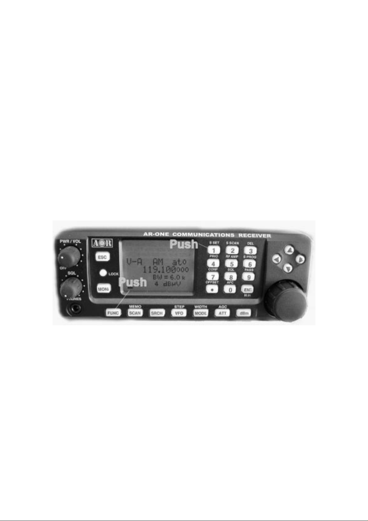
To access the configuration menu, push the FUNC key and then push the 7 key.
The first item in the co nf iguration menu is “BEEP”, the default is beep on with a volume
level of 06. Use the ma in t uni ng dial or the right arrow key or the left arrow key t o change
beep level between the ra nge of OFF and 01 to 09 being the loudest.
Push the ENT key to accept the data and return to a st andard display.
Page 51

50
Alternatively, push the ESC key to abort entry.
Or , push the down arrow key to move to the next it em o n t he configuration menu (LAMP).
6-2 Configure lamp
The AR-ONE is equipped with high intensity green LED s t o illuminate the LCD and keypad
when operating in areas of low level lighting.
The lamp may be configured in three ways:
AUTO The lamp will automatically ill uminate when the keypad or main tuning dial are
used.
The lamp will remain illu minat ed for further five second after the last key push and then
switch off. The lamp will also automatically il luminate while the squelch opens.
ON This is default setting. The lamp will continuously illu minat e the LCD and keypad.
OFF The lamp remains permanently extinguished, this is useful when used in areas of
high light levels.
To access the configuration menu, push the FUNC key and then push the 7 key.
Push the down arrow key to move the cursor to “LAMP” selection point.
Use the main tuning dial or the right arrow key or the left arrow key to toggle th e lamp
between AUTO, ON a nd OFF.
Push the ENT key to accept the data and return to a st andard display.
Alternatively, push the ESC key to abort entry.
Or , push the down arrow key to move to the next item on the configuration menu (DIMM).
6-3 Configure dimmer
A DIMM (dimmer) function is available to dim intensity of the LEDs. This function is useful
when used in areas of high light levels.
The default setting of DI MM is “OFF”.
Page 52

51
To access the configuration menu, push the FUNC key and then push the 7 key.
Push the down arrow key to move the cursor to “DIMM” selection point.
Use the main tuning dial or the right arrow key or the left arrow key to toggle th e dimmer
between ON and OFF.
Push the ENT key to accept the data and return to a st andard display.
Alternatively, push the ESC key to abort entry.
Or , push the down arrow key to move to the next it em o n t he configuration menu
(CONTRAST).
6-4 Configure contrast
The AR-ONE is equippe d w it h variable LCD contrast which is adjustable in 32 steps to
provide best visibility under different viewing angles, extremes of ambient light &
temperature (and between sets due to variat i on).
The default setting for contrast is 12. The display generally becomes too dark to read
around
20 and too feint around 02. Best result s are usually achieved within the range of 09 – 15.
To access the configuration menu, push the FUNC key and then push the 7 key.
Push the down arrow key to move the cursor to “CONTRAST” selection point.
Use the main tuning dial or the right arrow key or the left arrow key to vary the contrast
level
to achieve best visibility.
Push the ENT key to accept the data and return to a st andard display.
Alternatively, push the ESC key to abort entry.
Or , push the down arrow key to move to the next it em o n t he configuration menu
(OPENING M ESSAGE).
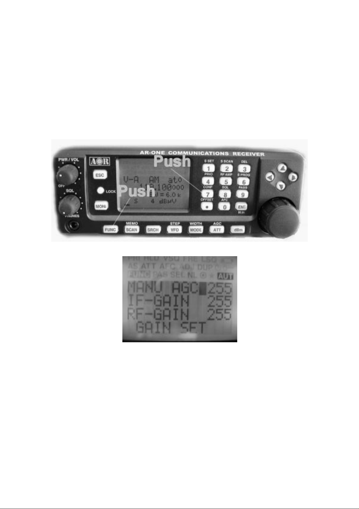
6-5 Configure Manual AGC
Page 53
52
The manual AGC funct i on is to adjust the receiver’s AGC (Automatic Gain Control) when it
is set OFF.
The default setting for Manual AGC is 255, maximum gain control value.
The value can be adjusted according to the receiving condition.
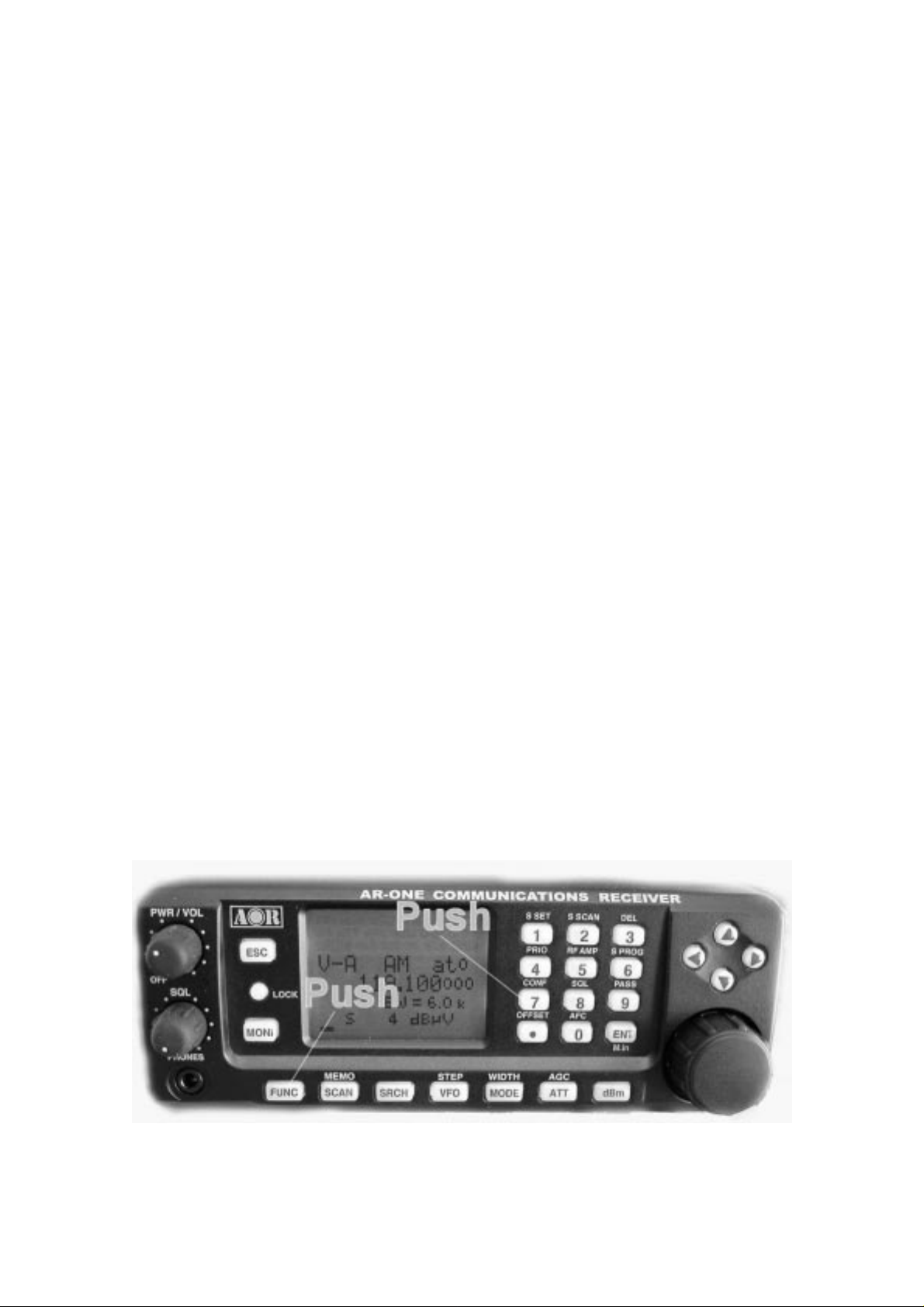
To access the configuration menu, push the FUNC key and then push the 7 key.
Push the down arrow key to move the cursor to “MANU AGC” selection point.
Use the main tuning dial or t he right arrow key or the left arrow key to vary the manua l AGC
level for best reception.
Push the ENT key to accept the data and return to a st andard display.
Alternatively, push the ESC key to abort entry.
Or , push the down arrow key to move to the next it em o n t he configuration menu
(IF-GAIN).
6-6 Configure IF-GAIN (Intermediate Frequency gain)
Page 54

53
The IF gain control reduces the amplification in the receiver’s IF circuits and has the effect
of
reducing the sensitiv ity of the receiver. Normally, this is performed by the AGC system, an d
the control is left at maximum gain, but reducing the gain can be use fu l t o li mit noise when
listening to CW or SSB signals. The IF gain control is must be used i f the AGC is turned off.
The default setting for IF-GAI N i s 255, maximum gain control value.
To access the configuration menu, push the FUNC key and then push the 7 key.
Push the down arrow key to move the cursor to “IF- GAIN” selection point.
Use the main tuning dial or the right arrow key or the left arrow key to vary t he IF-Gain
level for best reception.
Push the ENT key to accept the data and return to a st andard display.
Alternatively, push the ESC key to abort entry.
Or , push the down arrow key to move to the next it em o n t he configuration menu
(RF-GAIN).
6-7 Configure RF-GAIN (Radio Frequency gain)
The RF gain setting switches in the attenuator or preamplifier to suite the band cond it ions
and antenna in use.
The default setting for RF-GAIN is 255, maximum gain contro l value.
The value can be adjusted according to the receiving condition.
To access the configuration menu, push the FUNC key and then push the 7 key.
Push the down arrow key to move the cursor to “RF-GAIN” select ion point.
Use the main tuning dial or the right arrow key or the left arrow key to vary t he RF-Ga in
level for best reception.
Push the ENT key to accept the data and return to a st andard display.
Alternatively, push the ESC key to abort entry.
Page 55

54
Or , push the down arrow key to move to the next it em o n t he configuration menu (BPS).
6-8 Configure Remote BPS (Baud rate)
The Remote BPS Set menu is used to configure the RS-232C computer control settings as
it
is important that they exac t ly match those of an associated computer connection or another
AR-ONE (connected via a ma le 9-pin to mail 9-pin straight cable).
To access the configuration menu, push the FUNC key and then push the 7 key.
Push the down arrow key to move the cursor to “BPS SET” selection p oi nt.
Use the main tuning dial or the right arrow key or the left arrow key to select the desired
RS-232C baud rate between 4800bps and 9600bps. The default setting is 9600bps.
Push the ENT key to accept the data and return to a st andard display.
Alternatively, push the ESC key to abort entry.
Or, push the down arrow key to move to the next item on the configuration menu
(RMT-ID).
6-9 Configure RMT-ID (Remote ID)
When multiple units are connected via remote connectors, each AR-ONE must be assigned
a different ID (address).
The value is adjustable between 00 ~ 99. The default value is 00.
Important notice: It is extremely important to set the RMT-ID to 00 for normal operation
of the RS-232C connection.
Page 56
55
To access the configuration menu, push the FUNC key and then push the 7 key.
Push the down arrow key to move the cursor to “RMT-ID” selection point.
Use the main tuning dial or the right arrow key or the left arrow key to change the
AR-ONE’s
RS-232C identif ication address.
Push the ENT key to accept the data and return to a st andard display.
Alternatively, push the ESC key to abort entry.
Or, push the down arrow key to move to the next item on the configuration menu
(DELAY).
6-10 Configure DELAY (Scan delay and Search delay)
This parameter affect s t he time, the AR-ONE will remain on active frequency in scan mode
or search mode once the received signal has disappeared and the squelch has closed.
This
Is particularly useful for customizing how long the receiver w ill w ait f or a reply before
resuming scan or search. For example, w hen communications are passed back and forth
between a control tower / aircraft which may take a few seconds. The limits are OFF /
HOLD
and 0.1 to 0.9 seconds in 0.1 second increments. The default is 2. 0 seconds.
To access the configuration menu, push the FUNC key and then push the 7 key.
Push the down arrow key to move the cursor to “DELAY” selection point.
Page 57

56
Use the main tuning dial or t he right arrow key or the left arrow key to select the desired
delay parameters.
2.0s The AR-ONE will wait the specified time after the sque lch closes before
resuming scan or search.
HOLD The AR-ONE will stop indefinitely when an active frequency is located, this
is very useful when you don’t w ant to miss that once-in-a-lifeti me
transmission!
OFF The AR-ONE will resume scan or search instantaneously when the
squelch closes.
Push the ENT key to accept the data and return to a st andard display.
Alternatively, push the ESC key to abort entry.
Or , push the down arrow key to move to the next it em o n t he configuration menu (FREE).
6-11 Configure FREE (Scan free and Search free)
The scan free and search free p arameter determines how long the AR-ON E will remain on
active frequency before resuming scan or search even though the frequency is still active.
This is useful if you wis h t o gain a snap shot of activity without the AR-ONE being tied to a
busy frequency for long period s of t ime (such as when monitoring active commercial
repeaters etc). Scan free and search free time saves you having to manu ally intervene to
force the scan or search process to resume an d saves the need to lockout memory
channels or search frequencie s using the PASS function. The li mits are OFF and 0.1 to 9.9
seconds. The default setting is OFF.
To access the configuration menu, push the FUNC key and then push the 7 key.
Push the down arrow key to move the cursor to “FREE” selection p oi nt.
Use the main tuning dial or the right arrow key or the left arrow key to select the desired
free
parameters.
Push the ENT key to accept the data and return to a st andard display.
Alternatively, push the ESC key to abort entry.
Or , push the down arrow key to move to the next it em o n t he configuration menu
Page 58

57
(SPEAKER).
6-12 Configure SPEAKER
The AR-ONE is equippe d w it h 2 separate speakers, one is in the main rec eiver unit and the
another one is in the control head (Note: This function is available only when an optional
separation kit is used), and a phones jack. Each speaker / head phones output can be
configured under this menu.
6-12-1 Configure rear speaker
To access the configuration menu, push the
Push the down arrow key to move the cursor to “
This menu is to configure the rear speaker.
Use the main tuning dial or the right arrow key or the left arrow key to select the desired
rear
FUNC
key and then push the 7 key.
REAR SP
” selection point.
speaker setting (ON or OFF).
Push the
Alternatively, push the
Or , push the
SP).
6-12-2 Configure front spea ker
ENT
key to accept the data and return to a standard display.
ESC
key to abort entry.
down arrow key
to move to the next item on the configuration menu (FRONT
(Note: This function is available only when an option a l separation kit is used)
Page 59

58
To access the configuration menu, push the FUNC key and then push the 7 key.
Push the down arrow key to move the cursor to “F R ONT SP” se lection point.
This menu is to configure the front speaker.
Use the main tuning dial or the right arrow key or the left arrow key to select the desired
rear speaker setting (ON or OFF).
Push the ENT key to accept the data and return to a st andard display.
Alternatively, push the ESC key to abort entry.
Or , push the down arrow key to move to the next it em o n t he configuration menu
(PHONES).
6-12-3 Configure head phones output
Push the down arrow key to move the cursor to “PHONES” selection point.
This menu is to configure the headphones output.
Use the main tuning dial or t he right arrow key or the left arrow key to select the desired
head phones output settin g (To access the configuration menu, push the FUNC key and
then push the 7 key.
ON or OFF).
Push the ENT key to accept the data and return to a st andard display.
Alternatively, push the ESC key to abort entry.
Or, push the down arrow key to move to the next item on the configuration menu (Audio
Filter).
6-13 Configure audio filters (HPF / LPF)
The AR-ONE is equipped with an audio HPF (High Pass Filter) and a LPF (Low Pass
Filter).
6-13-1 Configure audio HPF (high pass fil t er )
The audio high pass filter is useful for limiting the audio b ass response (allowing higher
tones to pass) improving intell igibility in certain circumstances (such as low frequency
whistles on AM, SSB & CW).
Page 60

59
There are four available p ass frequencies: 50Hz, 200Hz, 300Hz, and 400Hz.
The higher the frequency the more limited the audio bandwidth. For h ighest fidelity for
listening, select 50Hz . The filter selection can be set to automode to select the proper filter
setting automatically.
The default is AUTO.
To access the configuration menu, push the FUNC key and then push the 7 key.
Push the down arrow key to move the cursor to “HPF” selectio n point.
This menu is to configure the high pass filter.
Use the main tuning dial or the right arrow key or the left arrow key to select the desired
high
Page 61

60
pass filter setting (AUTO / 50Hz / 200Hz / 300 Hz or 400Hz).
Push the ENT key to accept the data and return to a st andard display.
Alternatively, push the ESC key to abort entry.
Or , push the down arrow key to move to the next it em o n t he configuration menu (LPF).
6-13-2 Configure audio LPF (low pass filt er )
The audio low pass filter i s useful to cut off high tones (allowing l ow tones to pass) to
improve intelligibility of weak signals in clo se proximity to adjacent interference and to
remove hiss making listening for extended periods easier on the ears.
There are four available pass frequencies: 3KHz, 4KHz , 6KHz and 12KHz.
The lower the frequency the more limited the audio bandwidth. For h ighest fidelity for
listening, select 12.0KHz. The filter selection can be set t o automode to select the proper
filter setting automatically.
The default is AUTO.
To access the configuration menu, push the FUNC key and then push the 7 key.
Push the down arrow key to move the cursor to “LPF” selectio n point.
This menu is to configure the low pass filter.
Use the main tuning dial or the right arrow key or the left arrow key to select the desired
high
pass filter setting (AUTO / 3KHz / 4KHz / 6KHz or 12KHz).
Push the ENT key to accept the data and return to a st andard display.
Alternatively, push the ESC key to abort entry.
Or , push the down arrow key to move to the next it em o n t he configuration menu
(De-Emphasis).
6-14 Configure Audio De-emphasis
This is really only applicable to FM mode and affects t he sharp ness of recovered audio.
Page 62

61
The FM transmission in different world areas have been different defaults for de-emphasis.
For example, a value of 759 is selected in Europe, the recovered audi o w il l sound very
muffled.
The available range is as follows: THRU, 25uS, 50uS, 75 uS, and 750uS
The audio de-emphasis can be set t o aut omode to select the proper setting aut omat ically.
The default is AUTO.
To access the configuration menu, push the FUNC key and then push the 7 key.
Push the down arrow key to move the cursor to “De- Emphasis” selection point.
This menu is to configure the audio de-emphasis.
Use the main tuning dial or t he right arrow key or the left arrow key to select the desired
de-emphasis setting (AUTO / THRU / 25uS / 75uS or 750u S).
Push the ENT key to accept the data and return to a st andard display.
Alternatively, push the ESC key to abort entry.
Or , push the down arrow key to move to the next it em o n t he configuration menu
(PRIO-CH).
6-15 Configure PRIO-CH (Priority Channel)
The priority function enables you to carry on scanning, searching or mo nitoring while the
AR-ONE checks a selected freq uency for activity (taken from one of the 1,000 memory
channels periodically).
The priority checking is accomplished by momentarily tuning the receive circuit to the
priority
frequency to see if it is active. If the activity is found, the AR-ONE will remain on the active
frequency until the signal disappears. If no activity is detected, the receiver returns to the
VFO frequency, scan channel or search bank from where it orig inated.
The priority function has a large number of applications and is particularly useful for
Page 63

62
keeping
an eye on a distress frequency w hile scanning or searching another freque ncy band.
Note: Dependin g upon the frequency and mode stored as priority, an audible click may be
heard when the priority fu nction is in operation. This is quite normal and is caused by the
internal switching of circuitry necessary to accomplish the frequency change (as two
frequencies cannot simu ltaneously be monitored).
6-15-1 Engaging Priority channel
Once engaged, the freque ncy is checked for activity periodically by the preset period that is
set by the configuration menu.
To engage the priority function, push the FUNC key and then push t he 7 key.
Push the down arrow key to move the cursor to “PRIO-CH” select ion point.
This menu is to configure the priority channel.
Use the main tuning dial or t he right arrow key or the left arrow key to select the desired
priority channel.
Push the downward key to select the time interval.
Use the main tuning dial or the right arrow key or the left arrow key to select the desired
time
interval for the priority channel.
Push the ENT key to accept data and return to a standard display.
Alternatively, push the ESC key to abort entry.
Page 64

63
Or , push the down arrow key to move to the next it em o n t he configuration menu (IF
output).
6-16 Configure IF output frequency
The function enables you to tap the 2nd IF signal (10.7MHz) or the 3rd IF signal (455KHz)
from the BNC (marked as 10. 7MHz) type connector on the rear panel. The 10.7MHz of the
nd
2
IF signal is to be used with an opt ional SDU5500 or SDU5600 spectrum display unit for
signal analysis. The bandwidth at 10.7 MHz is +/- 5 MHz from the center frequency (10
MHz total).
6-16-1 Selecting IF output frequen cy
To engage the priority function, push the FUNC key and then p ush t he 7 key .
Push the down arrow key to move the cursor to “IF out SEL” selectio n point.
This menu is to select the I F out put frequency.
Use the main tuning dial or t he right arrow key or the left arrow key to select the desired
IF output frequency.
Push the ENT key to accept data and return to a standard display.
Alternatively, push the ESC key to abort entry.
Or, push the down arrow key to move to the next item on the configuration menu
(Reference Signal).
6-17 Configure reference signal source
Page 65

64
The function enables you to select the reference signal of the receiver.
The AR-ONE has built-in a stable reference oscil lator, however, an external high stability 10
MHz reference (such as off-air atomic coupled) can be accepted from the SMA connector
(marked as 10 MHz IN) on the rear panel of the AR-ONE.
Push the down arrow key to move the cursor to “REF SEL” select ion point.
Use the main tuning dial or t he right arrow key or the left arrow key to select the desired
reference signal source (i nt ernal or external). The default is INT.
Push the ENT key to accept data and return to a standard display.
Alternatively, push the ESC key to abort entry.
This completes the configuration settings.
7 Computer control
Connect the AR-ONE to o ne of t he serial port of a computer using an RS-232C cable
terminated in a 9-pin plug.
The RS-232C parameters may be defined using the OCNFIGURATION menu. Baud rates
(data transfer speed) may be set to 4800 or 9600 bps. It is also possible to set an ‘address’
to facilitate connection o f up to 99 AR-ONE to a single port for custom o perat ion, the
addresses may be set between t he limits of 01 to 99 with 00 representing single radio
operation.
7-1 How to send an RS-232C command
Each command comprises of tw o upper case letters (header) along with operations as
required. All command use ASCII code which MUST BE IN UPPER CASE (except for the
up
arrow key, down arrow key, right arrow key, left arrow key and re mote ID command (^A)
which are non-printable and use the control codes of ASCII). A terminal program running
on
a computer should be set to:
Baud rate: 4800 or 9600 bps (this should match the AR-ON E)
DATA BIT: 8
STOP BIT: 2
Page 66

65
PARITY: NONE
XFLOW: ONE
A multiple command entry is only valid where specified. Where a mult i ple command entry is
allowed, each command MUST be separated with a space “h20” (HEX DECIMAL). Each
command is completed and a [CR] or [CR][LF]. Although t here i s no l ocal echo, either [CR]
or specified response sho uld come back from the receiver after confirming the correct
command. If no response has been gained after a short while, the receiver ha s failed to
receive the command properly. Send a [CR] then re-send the comman d. Should problem
persist, check your connect ions a nd t r y reducing the RS-232C baud rate.
7-2 Power on the AR-ONE
Connect an RS-232C cabl e bet w een the AR-ONE and a PC, type any key to power up the
AR-ONE.
7-3 Detailed RS-232C command listing of the AR-ONE
X
QP
^Ann
EX
IDnn
7-3-1 RX MODE
Vx
MRmnn
MSm
SM
Power on
Power off
Remote ON
Remote off
Remote ID
Memory scan mode m: 0 – 9 (memory bank) (default: 000)
Memory select
Select VFO
Memory mode
x: any key to power on the AR-ONE
Power off
Hex value 0x01
Accept a value nn in the range of 00-99 for remote
connection
Remote off
To set: IDnn<CR> nn: 00-99
To read:ID<CR>
m: 0 – 9 (memory bank) n: 00 – 99 (memory
To set: Vx<CR> x:A – J (default :A)
channel)
(default: 000)
SSmm
mode
Search mode mm: 01 – 40 (search bank) (default: 01)
Page 67

66
To read: RX <CR>
Response: Memory manual mode
MR MXmnn RFnnnnnnnnnn STnnnnnn Aun MDn BWn ATn AMn TMxxxxxxxx
Memory scan mode
MS MXmnn RFnnnnnnnnnn STnnnnnn Aun MDn BWn ATn Amn
TMxxxxxxxx
Memory select mode
SM MXmnn RFnnnnnnnnnn STnnnnnn Aun MDn BWn Atn Amn
TMxxxxxxxx
Search mode
SSmm RFnnnnnnnnnn STnnnnnn Aun MDn BWn Atn Amn
TTxxxxxxxx
VFO mode
Vx RFnnnnnnnnnn STnnnnnn Aun MDn BWn Atn Amn (default:
VFO-A)
7-3-2 FREQUENCY
RF
RF
Vx Vx nnnnnnnnnn (entry in Hz format) x: A – J (VFO)
To read: RF <CR>
Response: RFnnnnnnnnnn (Hz)
7-3-3 STEP FREQUENC Y
ST
ST
ST
To read: ST <CR>
Response: STnnnnnn (Hz)
7-3-4 AUTO MODE
RFnnnnnnnnnn (entry in Hz format) (VFO mode only)
RFnn.nn (entry in MHz
format)
STnnnnnn (entry in Hz for mat) (not available in search mode)
STnn.nn (entry in KHz format) (not available in search mode)
STnn …nn (entry in KHz format ) (not available in search mode)
(VFO mode only)
AU
AUn
n: 0 Auto mode off
n: 1 Auto mode on
Page 68
67
To read: AU <CR>
Response: AUn
7-3-5 OPERATION MODE
MD
MDn (n: 0 - 6) Auto mode will be disabled by t his command
n=0 FM (BW=16KHz,HPF=50 Hz , LPF=3KHz,De-emphasis=750uS)
n=1 AM (BW=6KHz, HPF=50Hz, LPF=3KHz, De-emphasis=TH RU)
n=2 CW (BW=0.5KHz, HPF=50Hz, LPF=3KHz, De-emphasis=THRU)
n=3 USB (BW=3KHz, HPF=50Hz, LPF=3KHz, De-emphasis=THR U)
n=4 LSB (BW=3KHz, HPF=50Hz, LPF=3KHz, De-emphasis=THRU)
n=5 WFM (BW=200KHz, HPF=50Hz, LPF=12KHz, De-emphasis=75uS)
n=6 NFM (BW=8.5KHz, HPF=50Hz, LPF=3KHz, De-emph asi s=750uS)
To read: MD <CR>
Response: MDn
7-3-6 BAND WID TH
BW
BWn (n: 0 – 6) Auto mode will be disabled by this command
n=0 0.5KHz
n=1 3.0KHz
n=2 6.0KHz
n=3 8.5KHz
n=4 16KHz
n=5 30KHz
n=6 100KHz
n=7 200KHz
n=8 300KHz
n=9 5MHz
To read: BW <CR>
Response: BWn
7-3-7 HPF (High Pass Filter)
HP
HPn (n: 0 – 3 & F) Auto mode will be disabled by this command
n=0 50Hz
n=1 200Hz
n=2 300Hz
Page 69
68
n=3 400Hz
n=F AUTO
To read: HP <CR>
Response: HPn
7-3-8 LPF (Low Pass Filter)
LP
To read: LP <CR>
Response: LPn
7-3-9 AGC (Automatic Gain C ontrol)
AC
To read: AC <CR>
LPn (n: 0 – 3 & F) Auto mode will be disabled by this command
n=0 3KHz
n=1 4KHz
n=2 6KHz
n=3 12KHz
n=F AUTO
ACn (n: 0 – 2)
n=0 AGC - OFF
n=1 AGC - FAST
n=2 AGC - SLOW
n=3 AGC - MIDDLE
Response: ACn
7-3-10 DE-EMPHASI S
EN
To read: EN <CR>
Response: ENn or ENmn (m=5, AUTO)
ENn (n: 0 – 5) Auto mode will be disabled by this command
n=0 25uS
n=1 50uS
n=2 75uS
n=3 750uS
n=4 THRU
n=5 AUTO
Page 70

69
7-3-11 RF ATT (Attenuator)
AT
To read: AT <CR>
Response: ATn
7-3-12 RF AMP (Amplifier)
AM
To read: AM <CR>
Response: AMn
ATn (n: 0 –3)
n=0 0dB
n=1 10dB
n=2 20dB
n=3 AUTO
AMn (n: 0 – 2)
n=0 RF AMP OFF
n=1 RF AMP ON
n=2 RF AMP AUTO
7-3-13 BFO FREQ (Beat Frequency Oscillator Frequency)
BF
To read: BF <CR>
Response• BF +/-nnnn
7-3-14 N – SQ (Noise Squelch) THRESHOLD
RQ
To read: RQ <CR>
Response: RQ nnn
7-3-15 L – SQ (Level Squelch)
DB DBnnn (nnn: 000 – 255) Default: 000 (OFF)
BF +/-nnnn (nnnn: 0000 - +/- 3000Hz)
Available in CW, LSB, USB mode only
Default: CW +800Hz
USB +1500Hz
LSB -1500Hz
RQnnn (nnn: 000 – 255) Default: 000 (OFF)
To read: DB <CR>
Response: DB nnn
Page 71
70
7-3-16 AF GAIN
AG
To read: AG <CR>
Response: AG nnn
7-3-17 MANUAL GAIN (10.7 MHz AGC)
MG
To read: MG <CR>
Response: MG nnn
7-3-18 RF GAIN
RG
AGnnn (nnn: 000 –255) Default: 255
Note: The volum e control knob must be turned fully counterclockwis e
MGnnn (nnn: 000 – 255) Default: 255
Note: Available only when the AGC is set to OFF
RGnnn (nnn: 000 – 255) Default: 255
Note: The volume control knob must be turned fully
counterclockwise
To read: RG <CR>
Response: RG nnn
7-3-19 IF GAIN
IG
To read: IG <CR>
Response: IG nnn
7-3-20 SQUELCH SELE C T
SQ
To read: SQ <CR>
Response: SQn
7-3-21 SIGNA L LEVE L
IGnnn (nnn: 000 – 255) Default: 255
SQn (n: 0 or 1) Default: 0 (noise squelch)
n=0 Noise Squelch mode
n=1 Level Squelch mode
Page 72
71
LM To read: LM <CR>
Response
LSQm LMnnn --- When the level squelch is selected
7-3-22 AUTO SIGNAL LEVEL
LC
LCn (n: 0 or 1)
n:0 Auto Signal Level off
n:1 Auto Signal Level on
While n is set to 1, and the squelch is opened, a signal level and freque ncy data
will be sent
LSQm LMnnn --- When the level squelch is selected
NSQm LMnnn --- When the noise squelch is selected
m: 1 when the squelch is closed
(nnn: 000 – 999)
(nnn: 000 – 999)
m: 1 when the squelch is closed
m: 0 when the squelch is opened
(nnn: 000 – 999)
To read: LC <CR>
Response:
7-3-23 AUTO BA CKLI T
LA
To read: LA<CR>
Response: LAn
LCn
SQm LCnnn RFnnnnnnnnnn
m: 0 when the squelch is opened
m: 0 Noise squelch mode
m: 1 Level squelch mode
LAn (n: 0 - 2)
n: 0 LAMP OFF
n: 1 LAMP ON (Default)
n: 2 LAMP AUTO
(Will go off in 5 seconds after the squelch is closed)
7-3-24 BACKLIT ON/OFF
Page 73
72
BL
BLn (n: 0 or 1) Available when LA is set to 2 (Auto).
To read: BL<CR>
Response: BLn
7-3-25 BACKLIT DIMMER
LD
To read: LD<CR>
Response: LDn
7-3-26 LCD CONTRAST
LV
To read: L V<CR>
Response: LVnn
n: 0 BACKLIT OFF
n: 1 BACKLIT ON (Default)
LDn (n: 0 or 1)
n: 0 NORMAL (Default)
n: 1 DIMM
LVnn (nn: 00 – 31) (Default: 12)
7-3-27 BEEP LEVEL
BL
To read: BL<CR>
Response: BLn
7-3-28 SPEAKER SELECT
SO
To read: SO<CR>
Response: SOn
7-3-29 EXTERNAL SPEAKER
BLn (n: 0 – 9) (Default: 5)
SOn (n: 0 – 3) (Default: 3)
n: 0 FRONT OFF, REAR OFF
n: 1 REAR ON
n: 2 FRONT ON
n: 3 FRONT ON, REAR ON
PO
POn (n: 0 or 1)
n: 0 OFF (Default)
Page 74

73
n: 1 ON
To read: PO<CR>
Response: POn
7-3-30 DELAY TIME (SCA N DELAY AND SEA RCH DELAY)
DD
To read: DD<CR>
Response: DDn.n or DDFF
7-3-31 FREE SCAN
SP
To read: SP<CR>
Response: SPn.n
7-3-32 SIGNAL METE R DISPLAY
SF
DDn.n (n.n: 0.0 – 9.9 second) Default: 2.0 sec.
nn: FF (hold)
SPn.n (n.n: 0.0 – 9.9 second)
n.n : 0.0 FREE SCAN OFF (Default )
n.n: 0.1 – 9.9 sec.
SFn (n: 0 – 2)
n: 0 ANALOG DISPLAY
n: 1 DIGITAL DISPLAY in dBuV (Default)
n: 2 DIGITAL DISPLAY in dBm
To read: SF<CR>
Response: SFn
7-3-33 DUPLEX MODE
OF
To read: OF<CR>
Response: OF xnn
7-3-34 DUPLEX FREQU E NCY
OL
OFnnx (nn: 00 – 47) (00: OFF)
x: + or - (Offset direction)
OLmm nnnnnnnn00 (mm: 01 - 19)
nnnn…n: Offset frequency (in 100Hz step, <1GHz)
Page 75

74
To read: OL<CR>
Response: OLmm nnnnnnnnnn (10 digit)
7-3-35 SIGNA L LEVE L UNIT (in dBuV) – Read only
LU
LU nnn (-nnn – nnn) dBuV
To read: LU<CR>
Response: LU nnn
7-3-36 SIGNA L LEVE L UNIT (in dBm) – Read only
LB
LB nnn (-nnn – nnn) dBm
To read: LU<CR>
Response: LB nnn
7-3-37 SEARCH DATA SETTING – Write only
SE
SEnn (nn: 01 – 40 ) Bank number
SLnnnnnnnnnn (Lower Frequency)
SUnnnnnnnnnn (Upper Frequency)
AUn
STnnnnnn, MDn, BWn, ENn, ATn, AMn,
ACn, ,,,,
TTxxxxxxxx (Enter text as needed)
Example:
SE01, SL0124500000, SU0123900000, AU1,
ST002500,,,,,,
Note: Refer to individual command for details of each field
7-3-38 SEARCH DATA LIST – Read only
Page 76

75
SR
SR Read search data of the current search bank
SR% Search data in all search bank
SRn SLnnnnnnnnnn Sun nnnnnnnnn AUn MDn BWn ATn AMn TTxxxxxxxx
SRn --- (Blank)
7-3-39 PASS FREQUENCY – Write only
PW
7-3-40 PASS FREQUENCY LIST – Read only
PR
SRnn (nn: 01 – 40)
Search data in search bank 1 - 40
SRn (n: 1 - 10) 4
Search data in search bank 1- 10
PW Register a current freq. to Pass freq.
PWnnnnnnnnnnnn Regi st er t he freq. to Pass freq.
PRnn (nn: 01 – 40) Bank number
PR00 nnnnnnnnnn
PR01 nnnnnnnnnn
: :
PRmm --- (mm: 00 – 49)
Last channel will be 49 or blank (- - -)
7-3-41 DELETE PASS FREQUENCY – W r ite only
PD
7-3-42 DELETE SEARCH DATA WITH PASS FREQUENCY – Write only
QS
QSnn (nn: 01 – 40)
Delete search data and pass frequency on designated search
PDmmnn (mm: 01 – 40) Bank number
(nn: 00 – 49) Pass channel
PDmm%% (mm: 01- 40) Bank number
Delete all pass frequenci es on designated bank
number
bank
Page 77

76
7-3-43 TRANSF ER THE CURRENT SEARCH DATA TO VFO – Write only
QS%%
Delete all search data and pass frequencies on all search
banks
SV
7-3-44 MEMOR Y DATA SETTING – Write only
MX
[Example]: MXmnn
RFnnnnnnnnnn (Frequency)
AUn
STnnnnnn, MDn, BWn, ENn, ATn, AMn, ACn
MX -------- Write the current receiver data to the current bank and channel
MXmnn -- Write the current receiver data to the designated bank and
channel
SVn (n: 0 – 9)
n: 0 VFO – A
n: 1 VFO – B
: :
n:9 VFO – J (Default)
(m: 0 – 9) Bank number
(nn: 00 – 99) Memory channel
GAn
TMxxxxxxxx
Note: Refer to individual commands for details of each field.
7-3-45 MEMOR Y DATA LIST – Read only
MA
[Example]: MXmnn MPn GAn RFnnnnnnnnnn AUn MDn BWn ATn AMn
TMxxxxxxxx
7-3-46 SELECT MEMORY ON/OFF
MAn (n: 0 – 9) Bank number, Memory data bet w een CH00 to
CH10
MA Memory data for bank number higher than 10
GAn (n: 0 or 1) Memory select On/Off
Page 78

77
GA
n: 0 OFF
To read: GA<CR>
Response: GAn
7-3-47 SELECT MEMO RY LIST – Read only
GR
[Example]: GRnn mxx … nn (nn: channel number)
(m: memory bank)
(xx: memory channel)
7-3-48 DELETE MEMORY – Write only
MQn
GRnn (nn: 00 – 99) Memory channel on the designated ban k
GR%% All channels (100channels maximum)
GRn (n: 0 – 9 ) List of 10 channels data
GR Next 10 channels data
n: 1 ON
MQn (n:0 – 9 ) Bank number
7-3-49 TRANSFER ME MO RY DATA TO VFO – Write only
MV
7-3-50 RESET – Write only
RS
MQ%% All bank
MVn (n: 0 – 9 )
n: 0 VFO – A
n: 1 VFO – B
: :
n: 8 VFO – I (Default)
n: 9 VFO – J
RS After executing the RS command, turn off the power
and
turn back on. This initializes the flash memory.
(All Search data and memory data will be deleted)
Page 79

78
8 SPECIFICATIONS
Model: AR-ONE
Configuration: Triple conversion super heterodyne
Frequency coverage: 10 KHz ~ 3.3 GHz (no gap)
Receive mode: AM, NFM, WFM, USB, LSB, CW, DATA
Sensitivity: (AM mode – 10 dB S/N, NFM mode – 12 dB SINAD,
CW/SSB mode – 10 dB S/ N)
Page 80

79
10 ~ 40 KHz: CW 22.3 uV
40 ~ 100 KHz: AM – 4.5 uV, CW – 1.5 uV
100 KHz ~ 40 MHz: AM 2.5 uV, 2 ~ 40 MHz: AM – 1.5 uV,
SSB/CW – 0.7 uV, NFM – 0.89 uV
40 MHz ~ 1 GHz: AM – 0.89 uV, SS B/CW – 0.4 uV, NFM – 0.5 uV, WMF – 1.5 uV
1GHz ~ 2.5 GHz: AM – 0.7 uV, SSB/CW – 0.32 uV, NFM – 0.4 uV, WFM – 1.5 uV
2.5 GHz ~ 3.3 GHz: AM – 0.9 uV, SSB/CW – 0.35 uV, NFM – 0.5 uV, WFM – 1.5 uV
IF frequencies: 1
2
3
st
IF: 754 MHz / 265 MHz
nd
IF: 10.7 MHz
rd
IF: 455 KHz
Frequency steps: Standard steps: 1, 10, 50, 100, 500 Hz, 1, 2, 5, 6.25, 9, 10,
12.5,
25, 50, 100 KHz
Non standard steps: Less than 1 MHz (1Hz incremental)
Selectivity: BW - 6 dB -60 dB
0.5 KHz 0.5 KHz > < 2 KHz
3 KHz 3KHz > < 6 KHz
6 KHz 6 KHz> < 20 KHz
8.5 KHz 8.5 KHz > < 30 KHz
16 KHz 16 KHz > < 40 KHz
30 KHz 30 KHz > < 70 KHz
100 KHz 100 KHz > < 450 KHz
200 KHz 200 KHz > < 600 KHz
300 KHz 300 KHz > < 900 KHz
Spurious Sensitivity: 60 dB >
Adjacent Selectivity: 55 dB >
Dynamic Range: 90 dB >
Unwanted Spurious emission: < - 57 dBm
rd
3
IP: + 2 dBm > (- 1 dBm > above 2.5 GHz)
Frequency stability: +/- 0.1 ppm ( -10 ~ 50 C)
THD: 20 dB> ( < 10 %)
Audio Output: 2.0 w (at 8 ohms, THD < 10 %)
Power requirement: 13.5 V DC, < 2 amp. (@ 1 w audio output)
Antenna impedance: 50 ohm
Antenna Connector: N type
IF output level: -20 dBm (10.7 MHz or 455 KHz)
Page 81

80
External frequency standard input : 10 MHz (0 dBm +/- 3 dB)
Control interface: RS-232C
Operating temperature: -10 ~ 50 degree s (C) , -18 ~ 144 degrees (F)
Dimensions: 6-1/4 (w) x 2-1/4 (h) x 9-1/4 (d) (inch) (Projections excluded)
Weight: Approximately 4.5 lbs.
(Specifications are subject to change without notice or obligation.)
9 OPTIONAL ACCESSORIES
EXT-ONE
MM8600 Mobile mounting bracket (radio not included)
Separation kit (includes a control head adapter and 16 feet separation
cable)
10 LIMITED WARRANTY
AOR USA, Inc. (AOR) war r ant s its receivers as described below:
AOR will repair or exchange equipment as a result of defects in parts or workmanship for a
period of one year from th e dat e of original retail purchase fro m an authorized AOR dealer.
Page 82

81
Exclusions
The following items are n ot covered by the AOR limited warrant y:
1. Products that are damaged through accident, abuse, misuse, neglect , or user
modifications.
2. Problems that arise through failure to follow directio ns in t he owner’s manual.
3. Exposure of the product to adverse or severe weather conditions, including
temperature
extremes or water, including rainfall or i m mers ion.
4. Exposure to toxic materials, biohazards, radioactive materials or other contamination.
5. Repairs attempted by parties oth er than AOR or its authorized personne l.
6. Damage that results from impro per installation, including improper voltage and/or
reversed polarity, or exposure of a receiver to signal levels exceeding specifications.
7. Damage resulting through t he use of accessories from manufacturers other than AOR.
8. Equipment that has had serial numbers removed or altered in any way.
9. Damage that occurred as a result of sh ipment. Claims must be presented to t he carri er.
10. AOR is not responsible for any costs arisi ng from installation or reinstallat io n of the
equipment, nor for any co nsequential (such as loss of use) damage cl ai ms.
Obtaining Warranty Service
1. You are responsible for shipping the product to AOR and any related costs.
2. Warranty claim must be accompanied by a legible c opy of the original product purchase
receipt.
3. You must include a description o f t he problem(s) encountered with the product.
4. You must include your name, a valid ground shipping address (inclu di ng zip code) and
telephone contact information.
5. AOR will ship the repaired (or replaced) product by ground transport.
Limitations
Any and all implied wa rrant ies, including those pertaining to merchantability and utility for a
specific purpose are limite d t o the duration of this limited warranty.
AOR’s limits on warranty pertain only to the repair or, at its option, replacement of defective
products. AOR shall not be liable for any other damages, including consequential,
incidental
or otherwise, arising from any defect.
Page 83

82
Some states do not allow limitations on how long an implie d w arrant y lasts and may not
allow the exclusion of incidental or consequential damages. As such, the above limitations
may not apply in every case. This warranty gives you specific legal rights and you may
have
other rights that apply in your st at e.
If you have questions about this limited warranty, or the operation of your AOR product,
contact AOR at (310) 787-8615 during normal business hours (9 am ~ 5 pm Pacific Time
Zone), or write to AOR, 20655 S. Western Ave., Suite 112, Torrance, CA 90501. You may
also send a fax to AOR at (310) 787-8619. Additional information is available at the AOR
web site: www.aorusa.com
We suggest attaching your purchase receipt to this half of the warranty card and that you
keep this information in a secure location.
AOR Model Number __________________________
Serial Number ________________ ______ ___ ___ ____
Dealer Name ________________ ___ ______ ___ __ ___
Purchase Date ____________ ______ ___ ______ __ ___
Page 84

83
Manufacturer: AOR, LTD.
2-6-4, Misuji, Taito-Ku,
Tokyo, 111-0055, Japan
URL: www.aorja.com
e-mail: post@aorja.com
US distributor: AOR USA, INC.
20655 S. Western Ave. Suite 112
Torrance, CA 90501
Phone: 310-787-8615
Fax: 310-787-8619
URL: www.aorusa.com
e-mail: info@aorusa.com
 Loading...