

®
AR8600
MOBILE WIDE RANGE ALL MODE RECEIVER
530 kHz ~ 2040 MHz (MK2 = 3GHz)
OPERATING MANUAL

Section 1
(1) AR8600 Index
(1) Index .......................................................................................................................... 1
1-1 Introduction ................................................................................................................ 5
1-2 Take care of your radio .............................................................................................. 5
1-3 Attention while operating ............................................................................................ 6
1-4 Accessories supplied ................................................................................................. 7
1-5 Controls & functions .................................................................................................. 7
1-5-1 Keypad ................................................................................................................... 9
1-5-2 Summary of keys .................................................................................................... 10
1-5-3 Important controls ................................................................................................... 15
1-6 Power supply .............................................................................................................16
1-6-1 Optional internal battery (BP8600) .......................................................................... 16
1-6-2 Charging the optional BP8600 battery .................................................................... 17
1-6-3 Battery considerations ............................................................................................ 18
1-6-4 Cigar lighter lead .................................................................................................... 18
1-7 i.f. output and spectrum display ................................................................................. 19
(2) Making the AR8600 ready for operation .................................................................. 20
2-1 LCD (Liquid Crystal Display) ...................................................................................... 20
2-2 Connect the aerial (antenna) ..................................................................................... 21
2-3 Connect power .......................................................................................................... 21
2-4 Keypad and knobs... what you need to know ‘most’ .................................................. 22
2-4-1 ENTER key ............................................................................................................ 22
2-4-2 FUNCTION key ...................................................................................................... 22
2-4-3 PASS key ...............................................................................................................22
2-4-4 CLEAR key ............................................................................................................. 23
2-4-5 MONITOR key ........................................................................................................ 23
2-4-6 KEY lock ................................................................................................................ 23
2-4-7 STANDBY key ........................................................................................................ 23
(3) Basic manual operation of the receiver .................................................................. 24
3-1 Switching on for the first time .................................................................................... 24
3-2 2VFO twin VFO selection .......................................................................................... 24
3-3 Entering a frequency using the numeric keypad ........................................................ 26
3-4 Correcting frequency input ........................................................................................ 27
3-5 Changing frequency using the and keys ............................................................ 27
3-6 Changing frequency using the main dial .................................................................... 28
3-7 Changing receive mode ............................................................................................. 29
3-7-1 Auto-mode selection ............................................................................................... 29
3-7-2 Receive mode selection menu ................................................................................ 29
3-8 Changing tuning STEP size ....................................................................................... 31
3-9 STEP-adjust ..............................................................................................................33
3-9-1 Automatic calculation of step adjust ....................................................................... 33
3-9-2 Cancelling step adjust ............................................................................................ 34
3-9-3 Manual setting of step adjust .................................................................................. 34
3-10 FREQUENCY OFFSET ........................................................................................... 36
3-10-1 Using pre-programmed frequency offset data ....................................................... 36
3-10-2 Entering new frequency offset data ...................................................................... 37
3-11 Attenuator ................................................................................................................ 38
3-12 Noise limiter ............................................................................................................. 38
3-13 AFC - Automatic Frequency Control ........................................................................ 39
(4) VFO enhanced facilities ........................................................................................... 41
4-1 Quick memories ........................................................................................................ 41
4-1-1 Saving quick memory data ..................................................................................... 41
4-1-2 Recalling quick memories ...................................................................................... 42
4-2 VFO scan .................................................................................................................. 42
4-2-1 VFO SCAN sampling time ...................................................................................... 43
1

Section 1
4-3 VFO Search ...............................................................................................................43
4-3-1 Defining VFO search .............................................................................................. 43
4-3-2 Starting VFO search ............................................................................................... 43
4-3-3 Forcing VFO search to resume & changing search direction .................................. 44
4-3-4 Locking out unwanted frequencies (PASS) ............................................................ 44
4-3-5 Saving active frequencies to memory ..................................................................... 4 5
4-3-6 Exiting VFO search ................................................................................................ 46
4-4 VFO environment menu ............................................................................................ 46
4-4-1 VFO SCAN ............................................................................................................. 46
4-4-2 VFO search DELAY ................................................................................................ 46
4-4-3 VFO search LEVEL squelch .................................................................................... 47
4-4-4 VFO search VOICE squelch .................................................................................... 48
4-4-5 VFO FREE search ................................................................................................... 48
4-4-6 VFO AUTO STORE ................................................................................................. 49
4-4-7 VFO DELETE bank “J” ............................................................................................ 49
4-4-8 VFO QUICK MEMORY ............................................................................................ 50
(5) Memory channels & banks ...................................................................................... 51
5-1 Memory channel overview ......................................................................................... 51
5-2 Storing VFO frequencies & data into memory ............................................................ 52
5-2-1 Another example of memory write .......................................................................... 54
5-2-2 Automatic memory allocation ................................................................................. 55
5-3 Memory write protect ................................................................................................. 55
5-4 Memory read “M.RD” ................................................................................................. 56
5-4-1 Memory channel review / hunt ................................................................................ 57
5-5 Deleting memory channels ........................................................................................ 57
5-5-1 Memory channel editing ......................................................................................... 57
5-5-2 Adding text names to memory banks ..................................................................... 58
5-6 Transfer of memory channel to VFO .......................................................................... 58
5-7 Dynamic memory bank resizing ................................................................................. 58
(6) Priority operation ..................................................................................................... 59
6-1 Engaging PRIORITY channel .................................................................................... 60
6-2 Changing PRIORITY channel data ............................................................................ 60
6-2-1 Changing the priority channel data pickup channel ................................................ 61
6-2-2 Changing priority interval time ................................................................................ 61
(7) SCAN - scanning memory channels & banks ......................................................... 62
7-1 SCAN - outline introduction ....................................................................................... 62
7-2 SCAN considerations ................................................................................................ 62
7-3 Starting to SCAN ....................................................................................................... 63
7-3-1 Transfer of active memory to VFO .......................................................................... 64
7-4 Selecting a scan bank ............................................................................................... 64
7-5 Channel PASS ........................................................................................................... 64
7-5-1 Toggling memory channel PASS ............................................................................ 65
7-5-2 Removing ALL memory PASS tags in one go ........................................................ 65
7-6 Deleting memory channels ........................................................................................ 66
7-6-1 Deleting single memory channels ........................................................................... 6 6
7-6-2 Deleting whole memory banks in one go ................................................................ 66
7-7 Scan bank link (scan group) ...................................................................................... 66
7-8 Additional scan facilities ............................................................................................ 67
7-8-1 Scan DELAY .......................................................................................................... 68
7-8-2 Scan LEVEL ........................................................................................................... 68
7-8-3 Scan VOICE ........................................................................................................... 69
7-8-4 Scan FREE ............................................................................................................ 70
7-8-5 Scan (receive) MODE ............................................................................................ 70
7-8-6 Write protect of memory channels & banks ............................................................ 71
7-9 Select scan ................................................................................................................ 71
7-9-1 Adding select scan channels in memory read ........................................................ 71
7-9-2 Starting / stopping select scan .............................................................................. 71
2

Section 1
7-9-3 Select scan environment ........................................................................................ 72
7-9-4 Editing the contents of the select scan list .............................................................. 72
7-9-5 Deleting all select scan channels ........................................................................... 73
(8) Search mode ............................................................................................................. 74
8-1 Search types .............................................................................................................74
8-1-1 Program search overview ....................................................................................... 7 4
8-2 Starting program search ............................................................................................ 75
8-2-1 Reversing the direction of search ........................................................................... 75
8-2-2 Forcing the search to resume ................................................................................. 75
8-2-3 Stopping the search ............................................................................................... 75
8-2-4 Copying an active frequency to the VFO or memory location ................................. 7 6
8-3 Selection of search bank ........................................................................................... 76
8-4 Programming a search bank ..................................................................................... 78
8-5 Locking out unwanted active frequencies (PASS) ..................................................... 80
8-5-1 Search pass menu ................................................................................................. 80
8-6 Search bank link ........................................................................................................ 81
8-7 Additional search facilities ......................................................................................... 82
8-7-1 Search DELAY ....................................................................................................... 83
8-7-2 Search LEVEL ....................................................................................................... 84
8-7-3 Search VOICE ........................................................................................................ 84
8-7-4 Search FREE ......................................................................................................... 85
8-7-5 AUTO STORE ........................................................................................................ 86
8-7-6 DELETE bank “J” ................................................................................................... 86
8-7-7 Deleting search banks ............................................................................................ 87
8-7-8 Write protect and copying search banks ................................................................ 87
(9) EDIT menu ................................................................................................................88
9-1 EDIT COPY memory channel .................................................................................... 88
9-2 EDIT COPY memory bank ......................................................................................... 89
9-3 EDIT COPY search bank ........................................................................................... 90
9-4 EDIT MOVE memory channel .................................................................................... 90
9-5 EDIT SWAP memory channel ................................................................................... 91
9-6 EDIT memory channel ............................................................................................... 92
9-7 EDIT Search protect .................................................................................................. 93
(10) DELETE menu facilities ......................................................................................... 94
10-1 DELETE search banks and search PASS frequencies ............................................ 94
10-2 DELETE VFO PASS ................................................................................................ 95
10-3 DELETE memory bank ............................................................................................ 95
10-4 DELETE select scan channels ................................................................................. 96
10-5 DELETE memory channel protect ........................................................................... 96
10-6 DELETE memory channel pass ............................................................................... 9 7
(11) Write protect ...........................................................................................................98
11-1 Memory CHANNEL write protect ............................................................................. 98
11-2 Write protect during memory input ........................................................................... 9 8
11-3 Channel protect status for existing memory channels .............................................. 98
11-4 Channel protect delete ............................................................................................ 99
11-5 Memory BANK write protect .................................................................................... 99
11-6 Search bank write protect ........................................................................................ 100
11-7 Global write protect ................................................................................................. 100
(12) TEXT search and input ........................................................................................... 101
12-1 Text input menus ..................................................................................................... 101
12-2 Text search ............................................................................................................. 102
(13) SHORT CUT keys ................................................................................................... 103
13-1 Short cut menu access ............................................................................................ 103
13-2 Short cut text entry .................................................................................................. 104
13-3 Short cut text entry, keypad with keys ........................................................ 105
3

Section 1
(14) Configuration menu ................................................................................................ 106
14-1 CONFIG BEEP ........................................................................................................ 106
14-2 CONFIG LAMP ........................................................................................................ 106
14-3 CONFIG CONTRAST .............................................................................................. 107
14-4 CONFIG Auto power off ........................................................................................... 107
14-5 CONFIG Remote RS232 ......................................................................................... 108
14-6 CONFIG FREQ DISP .............................................................................................. 108
14-7 CONFIG GLOBAL write protect ............................................................................... 109
14-8 CONFIG Opening message ..................................................................................... 109
(15) Band scope ............................................................................................................. 110
15-1 Starting the band scope .......................................................................................... 110
15-2 Exit from band scope ............................................................................................... 111
15-3 Setting frequency span width (waveform enlargement) ........................................... 111
15-4 Moving the marker ................................................................................................... 112
15-5 Marker to strongest signal (peak search) ................................................................. 112
15-6 Entering a new centre frequency ............................................................................. 11 2
15-7 Transfer of marker frequency to VFO ...................................................................... 112
15-8 Peak hold ................................................................................................................ 113
15-9 Saving active trace to memory ................................................................................ 113
15-10 Loading stored band scope traces from memory ................................................... 113
(16) Sleep ....................................................................................................................... 114
(17) Computer control RS232 ........................................................................................ 114
17-1 How to send an RS232 command ........................................................................... 114
17-2 Brief command index (RS232) ................................................................................. 115
17-3 Detailed RS232 command listing ............................................................................. 116
17-4 Clone of data via the RS232 socket ......................................................................... 122
17-4-1 How to clone data ................................................................................................. 123
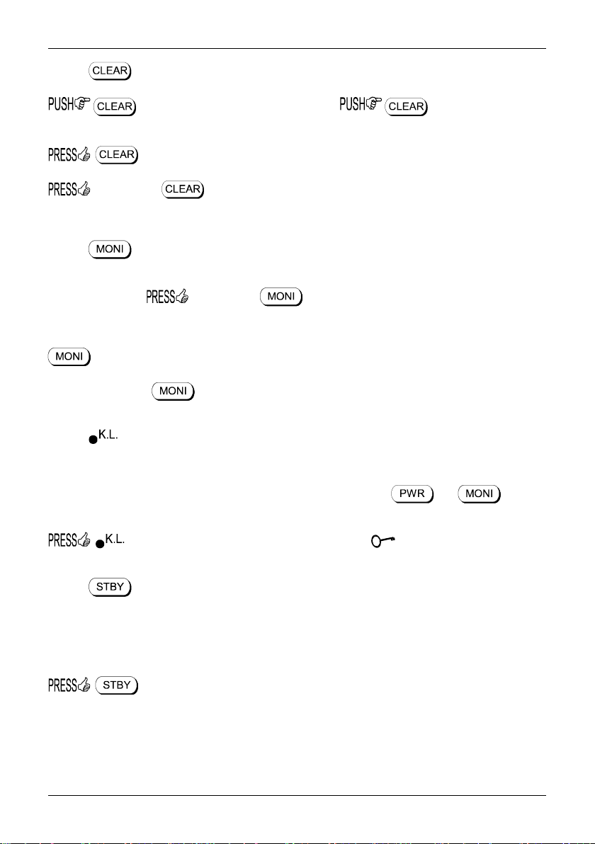
(18) Slot card socket ...................................................................................................... 124
18-1 Optional slot cards ................................................................................................... 124
18-1-1 Fitting the slot card ............................................................................................... 125
18-1-2 Removing the slot card ......................................................................................... 125
18-2 Slot card option menu - registering cards ................................................................ 125
18-3 TE8200 optional tone eliminator slot card ................................................................ 12 6
18-4 CT8200 optional CTCSS slot card ........................................................................... 127
18-4-1 CTCSS tone squelch ............................................................................................ 128
18-4-2 CTCSS search ..................................................................................................... 129
18-5 VI8200 optional voice invertor slot card ................................................................... 129
18-6 RU8200 optional record & playback slot card .......................................................... 130
18-6-1 Recording ............................................................................................................. 130
18-6-2 Playback .............................................................................................................. 131
18-7 EM8200 optional external extended memory slot card ............................................ 132
18-7-1 Initialising (formatting) the EM8200 before use .................................................... 132
18-7-2 EM8200 ALL-DATA save and load ....................................................................... 133
18-7-3 EM8200 ALL-MEM save and load ........................................................................ 134
18-7-4 EM8200 MEMORY BANK save and load ............................................................. 135
18-7-5 EM8200 ALL-SRCH save and load ...................................................................... 135
18-7-6 EM8200 SEARCH BANK save and load .............................................................. 136
18-7-7 EM8200 internally stored band scope save and load ............................................ 13 7
(19) Trouble shooting .................................................................................................... 139
19-1 Soft reset of microprocessor .................................................................................... 139
19-2 Other trouble shooting suggestions ......................................................................... 13 9
19-3 Trouble shooting - Take note of the following .......................................................... 140
(20) Optional accessories ............................................................................................. 141
(21) Aerial (antenna), earths & propagation ................................................................. 142
(22) Specification ........................................................................................................... 143
4

Section 1-1, 1-2
1-1 Introduction
Thank you for purchasing the AR8600 transportable wide band all mode receiver. The AR8600 is
designed using the very latest technology to ensure the highest levels of performance and reliability.
To get the best possible results from your AR8600 we recommend that you read this manual and
familiarise yourself with the receiver. Although carefully designed, this receiver (like all receivers)
suffers from a degree of internal noises known as spurii. They are a product of the receiver’s circuitry
and do not represent a fault. Apparent faults may be due to accidental misoperation of the receiver, if
you think there is a problem, carefully read all of the manual before deciding to contact your equipment
supplier for advice.
It is acknowledged that sections of this manual are repetitive, this is to enable the manual to be used as
a reference book (you don’t have to read it all from cover to cover in one go). Due to the international
nature of the product, some graphics contain Japanese characters.
Every effort has been made to make this manual correct and up to date. Due to continuous
development of the receiver and by error or omission anomalies may be found and this is
acknowledged.
© This manual is protected by copyright AOR Ltd 2000. No information contained in this manual may be
copied or transferred by any means without the prior written consent of AOR Ltd. AOR and the AOR
logo are trade marks of AOR Ltd. All other trade marks and names are acknowledged. E&OE
1-2 Take care of your radio
There are no internal operator adjustments. In the unlikely event of servicing being required, please
contact your dealer for technical assistance.
Do not use or leave the receiver in direct sunlight (especially the LCD). It is best to avoid locations
where excessive heat, humidity, dust and vibration are expected. Always keep the AR8600 free from
dust and moisture. Use a soft, dry cloth to gently wipe the set clean, never use abrasive cleaners or
organic solvents which may damage certain parts. Treat the AR8600 with care, avoid spillage or
leakage of liquids into the receiver and associated power supply. Special care should be taken to
avoid liquid entering around the controls, through the speaker grille or via the connection jacks.
The AR8600 is designed for operation from a good quality regulated d.c. supply of 12 to 14V, which
should be capable of supplying 1Ampre. Never connect the AR8600 directly to the a.c. supply.
The AR8600 also has the provision of the optional BP8600 NiCad battery pack, see section 1-6-1.
The d.c. input socket uses a 2.1mm power connector. This connector is configured CENTRE
POSITIVE, the chassis of the receiver is at negative ground. Where provided (depending upon world
market location), the power supply is pre-wired and provides a nominal 12V d.c. output with suitable
connectors being fitted as standard for the a.c. power input and connection to the AR8600.
SAFETY NOTICE - Always disconnect the power supply from the a.c. socket when not in use.
If using the AR8600 in a base station situation, the best short wave reception is usually achieved by the
fitting of a separate external earth rod, however consider the implications carefully if your a.c. building
supply uses a Protective Multiple Earth (PME) system. If in doubt consult an expert electrician. Never
earth to a gas pipe!
The AR8600 has a single BNC aerial socket for all frequencies. This is intended for connection to its
supplied whip aerial or preferably a 50 OHM (unbalanced) coaxial fed aerial such as a discone, dipole,
unipole, yagi etc. When sighting the aerial, avoid power cables. Ensure that you do not confuse the
aerial and i.f. output sockets as they both employ BNC sockets.
If used mobile, it should be noted that the AR8600 has not been manufactured
or tested to meet any specific mobile safely requirements. The AR8600 has no internally
user adjustable parts, refer any technical work such as the fitting of the optional
BP8600 internal NiCad battery pack to an authorised service engineer.
5

Section 1-2, 1-3
Operating anomalies
Should the AR8600 appear to behave strangely, normal operation may be easily achieved by resetting
the microprocessor. Two scenarios may be encountered due to power transients etc:
1. Symptom: LCD remains on, no control of the keypad.
Action: Remove any connection to external power such as the power supply or cigar
2. Symptom: The AR8600 fails to power up.
Action: Try the suggestion given in (1) then hold the key while powering up the
lead (remove the optional BP8600 internal NiCad battery pack if fitted) and
count to thirty! Reconnect power (or refit the battery) and switch on again.
Normal operation should be restored but the last used frequency will be lost, the
AR8600 will restore the last but one frequency to display.
AR8600 to ‘Soft reset’ the microprocessor.
1-3 Attention while operating
1. Certain key operations are acted upon when the key is RELEASED, not while it is pressed.
Allow time for the AR8600 to register such actions before pressing another key.
2. The keylock is intentionally made to be difficult to operate to prevent accidental operation.
To release keylock, the key has to be held for more than one second, the key legend on the
LCD confirms operation. The key is disabled during keying sequences (such as when
entering frequencies).
3. If a key sequence is not completed, the microprocessor will automatically abort most operations
after about 90 seconds of keypad inactivity.
4. Currently displayed VFO data is saved at power down (to increase speed of operation and to
reduce write cycles). For this reason, if the AR8600 is powered down using the PWR/VOL control or
external power is removed (without the optional internal BP8600 battery fitted or becomes
exhausted), the last displayed frequency will be lost and the frequency used prior to this will be
displayed when next powered up.
Terminology - Search & Scan
If you have not used a wide range monitor before or are not familiar with the terminology used, it is very
important to understand the difference between SEARCH and SCAN modes.
SEARCH: The AR8600 provides several operations where transmissions (active frequencies) may
be automatically located by sweeping the receiver over a wide frequency range, either from the
currently displayed frequency travelling upwards (or downwards) in a specified tuning increment
(step) or by sweeping over-and-over between two specified frequency limits. This process is known
as SEARCHING, as the title implies, it can take a long time to find transmissions due to their ‘often
intermittent’ and brief nature. For this reason it is best to slice large frequency ranges into smaller,
more manageable pieces where they may be intensively studied.
When examining large frequency bands, it is common to find that 90% of frequencies are inactive
and only a small number of the remaining constitute what you really want. Searching still remains
the best way to initially locate active and interesting transmissions (in conjunction with a good
frequency listing and band plan).
SCAN: Once active transmissions have been identified (either by searching or by using a good
frequency guide), it is more efficient to store the data into memories which can be rapidly and
automatically monitored in succession stopping when activity is encountered. This forms a much
more efficient means of monitoring the most wanted frequencies as you have targeted 100% what
you most want to hear, by contrast searching is very inefficient for day-to-day monitoring.
6
Section 1-3, 1-4, 1-5
Note: It is very important that the squelch is advanced to cancel background noise for the
search & scan facilities to operate. This is because the AR8600 believes that it has found an
active frequency when the squelch opens and “S” ‘squelch open’ legend is displayed to the left
of the signal meter. Advance the squelch control clockwise until the background noise is just
cancelled, this is known as the threshold position. If the squelch control is advanced too far,
weaker signals may be missed.
No noise and no “S” legend displayed (with squelch advanced clockwise passed
threshold) = squelch closed.
Signal received or ‘noise’ emanating from speaker (squelch fully anti-clockwise, below
threshold) with “S” legend displayed = squelch open.
1-4 Accessories supplied
The following items are provided in the carton box:
1 x AR8600 receiver
1 x Whip aerial on a right-angle BNC connector (RA8600)
1 x Medium Wave (MW) bar aerial
1 x Power supply (may be supplied in some world market areas and in a separate carton)
1 x Operating manual (this booklet)
1-5 Controls & functions
Controls are located on the front with most connection sockets on the rear of the AR8600, a brief
identification is given here:
See over for a further description...
7
Section 1-5
Front cabinet
1. Rotary volume control plus isolate power On/Off
2. Rotary squelch control
3. Phones socket 3.5mm (mono or stereo may be used)
4. Standby key, for daily use as On/Off
5. Key Lock key
6. Monitor key
7. Function key
8. Clear / option key
9. LCD (Liquid Crystal Display)
10. Main keyboard (ten keys plus decimal and enter)
11. Arrow keys (frequency change and menu manipulation)
12. Main rotary dial (frequency change and menu manipulation)
Rear cabinet
13. IF output (10.7MHz) for connection to the SDU5500
Spectrum Display Unit (requires internal activation in a workshop)
14. Serial number plate
15. BC ANT, medium wave bar aerial connection
16. ANT BNC aerial socket (all frequencies)
17. REMOTE RS232 socket (9-pin D-type)
18. ACC socket, 8-pin mini-DIN, tape record etc
19. EXT.SP speaker socket 3.5mm mono 8 OHMS
20. DC 12V d.c. input nominal 12V @ 1A (centre positive)
21. RU8200 socket for record / playback slot card
22. EM8200 socket for external memory slot card
23. VI8200 socket for analogue voice inverter slot card
24. CT8200 socket for CTCSS slot card
25. TE8200 socket for audio tone eliminator slot card
RS232 connection requirements:
The REMOTE RS232 socket (17 above) is designed for connection directly to an RS232 serial port of a
computer such as a PC. No interface is required, just a standard RS232 lead... avoid nul-modem leads
as they are not suitable. Connections for a PC are as follows:
AR8600 PC 9 way RS232
22
33
5 5 GROUND
77
88
AR8600 PC 25 way RS232
23
32
5 7 GROUND
74
85
ACC connections
1 12V d.c. output max
current 30mA
2 Detector output (without audio
filtering). 180mV RMS @
100k OHMS or greater
3 N/C
4 & 5 Tape motor switching contact for low voltage 12V d.c.,
max current 350mA with insulating voltage of 40V
Switch on impedance is 1.2 OHMS
6 High level audio output 15mV RMS @ 10k OHMS
7 Low level audio output 0.7mV @ 10k OHMS
8 Ground
8

Section 1-5-1
1-5-1 Keypad
Keypad conventions
Most keys have multiple functions, their functions are printed on the cabinet. However due the
restriction of available size, not all facilities can be shown on the keypad printing. To ease access to
the many facilities, two formats are employed:-
Push and release the key quickly to access the required facility. This applies to
primary facilities of keys such as numeric 1, 2, 3 etc. Also for example, quickly the
key while in 2VFO mode to toggle between the two VFOs VFO-A and VFO-B.
Press and HOLD the key for more than one second to access the second
function, sometimes this is in conjunction with the key.
Function key manipulation
The key also may be used by PUSH and PRESS depending upon the specific
requirement, in most cases however the key will require a simple PUSH.
“FUNC” LCD legend solid =
“FUNC” LCD legend flashing =
9
Section 1-5-2
1-5-2 Summary of keys
The keypad is split into four areas of the front cabinet of the AR8600, the ‘ten keys’ for frequency
access, the bottom row for VFO, SCAN, SEARCH operations, three on the left for standby, key lock,
monitor and a group of four arrow keys on the right for frequency control and manipulation of menus.
When initially powered, the lamp is configured to AUTO, the lamp will be permanently illuminated when
connected to external power and when running from the optional BP8600 internal battery pack, the lamp
will automatically illuminate when keys are pressed and will stay illuminated for five seconds after the
last key press. It is possible to configure the lamp to OFF and CONTINUOUS in addition to AUTO.
An RS232 lead is required for computer control, various optional SLOT CARDS are available which
further extend the AR8600 facilities (and menus).
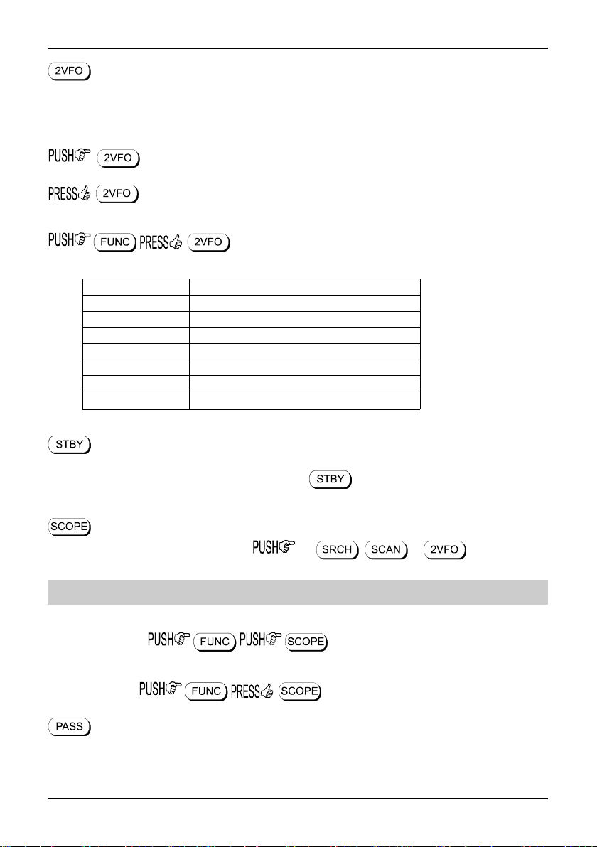
PUSH this key to place the AR8600 into SEARCH mode, the LCD “SRCH” legend confirms operation.
to access the bank link menu where up to ten different selections
of linked search banks may be grouped, this is useful where a large frequency band has been split up
into smaller more manageable sizes for close scrutiny.
Additional search related parameters may be set up to optimise each search group independently using
this menu:-
DELAY OFF / HOLD / 0.1s to 9.9s (default = OFF)
LEVEL OFF / 1 to 255 (default = OFF)
VOICE OFF / 1 to 255 (default = OFF)
FREE OFF / 1s to 60s (default = OFF)
AUTOSTORE ON / OFF (default = OFF)
DELETE J (deletes the current data from bank J)
PUSH this key to place the AR8600 into MEMORY READ mode, the LCD legend “M.RD” confirms
selection. again to initiate SCAN, the LCD legend “SCAN” confirms selection
to access the bank link menu where up to ten groups of memories
may be selected to be scanned in succession, effectively forming one large scan bank. Additional scan
related parameters may be set up to optimise each scan group independently using this menu:-
DELAY OFF / HOLD / 0.1s to 9.9s (default = OFF)
LEVEL OFF / 1 to 255 (default = OFF)
VOICE OFF / 1 to 255 (default = OFF)
FREE OFF / 1s to 60s (default = OFF)
MODE SCAN ALL / WFM / NFM / SFM / WAM / AM
/ NAM / USB / LSB / CW (default = ALL)
to set the ratio of bank size between memory channels sharing a
common letter in upper and lower case.
10
Section 1-5-2
PUSH this key to place the AR8600 into 2VFO mode where you may receive spot frequencies and
‘generally monitor activity’. The LCD displays two lines of frequency readout, the upper (larger) being
the current receive frequency. The LCD legend “2VFO” confirms selection with each VFO being
identified as “V-A” and “V-B”.
again to toggle between VFO-A “V-A” and VFO-B “V-B”.
to initiate VFO search between the two displayed frequency limits set by VFO-A and
VFO-B, the legend “V-SR” confirms selection of VFO SEARCH.
to access the VFO MODE select menu where the following
parameters may be configured:-
VFO SCAN ON / OFF (default = OFF)
DELAY OFF / HOLD / 0.1s to 9.9s (default = OFF)
LEVEL OFF / 1 to 255 (default = OFF)
VOICE OFF / 1 to 255 (default = OFF)
FREE OFF / 1s to 60s (default = OFF)
AUTOSTORE ON / OFF (default = OFF)
DELETE J (deletes the current data from bank J)
QUICK MEMORY OFF / 10s to 990s (default = OFF)
PRESS this key to switch the AR8600 on and off as a toggle. The main PWR/VOL control must be ‘on’
in order for the STANDBY switch to operate. Hold the key for more than one second for the
press to be registered.
PUSH this key to activate the band scope, the , or key to return to
normal operation.
Note: Priority operation is disabled when the band scope facility is in use.
Traces will be overwritten as the band scope is written from left to right on the LCD. To build up a long
term activity display, to toggle the PEAK HOLD facility on / off, the
LCD legend “HLD” confirms operation.
The key sequence recalls a previously saved band scope trace.
PUSH this key to PASS (lockout) memory channels during memory read & scan mode and to PASS
(skip) unwanted frequencies in search mode. Also acts as select ON/OFF/DEFAULT toggle in various
menus.
11
Section 1-5-2
in 2VFO mode to access the VFO PASS menu which extends to include the
SEARCH bank pass edit menu.
in 2VFO, SEARCH or SCAN mode to access the SELECT SCAN
edit menu.
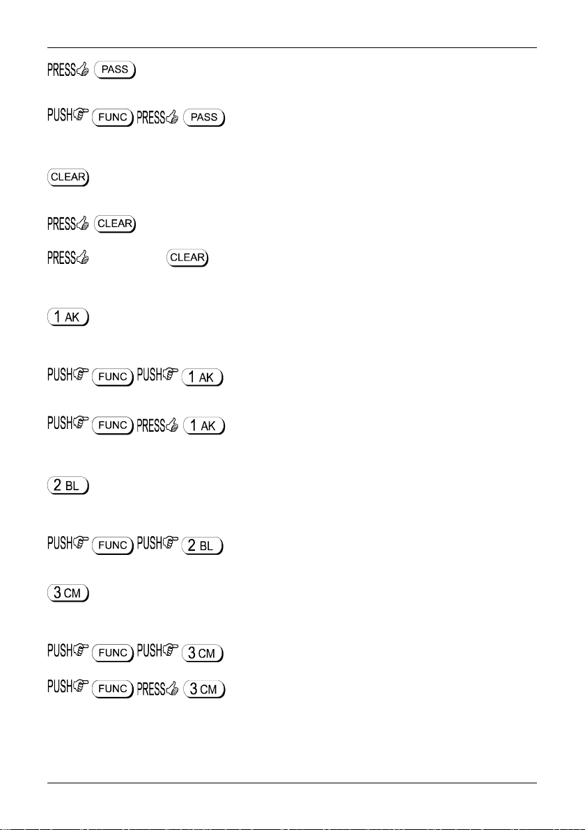
PUSH to abort entry via the keypad.
to select the optional SLOT CARD when fitted.
and HOLD the key while powering On the AR8600 to soft reset the microprocessor
should the AR8600 appear to behave strangely... no memory contents will be lost.
Numeric figure one during frequency input. Selection of memory/scan bank “A” or “a” and search bank
“A” or “a” or “K” or “k”.
to toggle the attenuator on / off, the LCD legend “ATT” confirms
operation.
to toggle the noise limiter on / off, the LCD legend “NL” confirms
operation.
Numeric figure two during frequency input. Selection of memory/scan bank “B” or “b” and search bank
“B” or “b” or “L” or “l”.
to access the tuning STEP size (increment) menu.
Numeric figure three during frequency input. Selection of memory/scan bank “C” or “c” and search bank
“C” or “c” or “M” or “m”.
to access the receive mode selection menu.
to select AUTO-MODE where the receiver mode and tuning step
are automatically selected by the AR8600 microprocessor from the pre-programmed band plan data
(this is a short cut to save using the receive mode menu). The LCD legend “AUT” confirms that
auto-mode is in operation.
12

Section 1-5-2
Numeric figure four during frequency input. Selection of memory/scan bank “D” or “d” and search bank
“D” or “d” or “N” or “n”.
toggles the priority facility on/off (assuming that one has already
been assigned using the priority menu). The LCD legend “PRI” confirms when priority has been
selected.
to access the priority menu where the data from a memory
channel may be assigned for priority use. The interval sampling time may also be specified.
Numeric figure five during frequency input. Selection of memory/scan bank “E” or “e” and search bank
“E” or “e” or “O” or “o”.
to initiate select scan (assuming that more than one memory
channel has already been tagged for select scan). The LCD legend “SEL” indicates when select scan is
active. or or to exit select scan.
Numeric figure six during frequency input. Selection of memory/scan bank “F” or “f” and search bank
“F” or “f” or “P” or “p”.
to access the program search menu where upper / lower
frequency limits etc for search mode may be entered.
Numeric figure seven during frequency input. Selection of memory/scan bank “G” or “g” and search
bank “G” or “g” or “Q” or “q”.
to access the configuration menu where the beep, lamp, LCD
contrast, RS232 etc. may be configured.
Numeric figure eight during frequency input. Selection of memory/scan bank “H” or “h” and search bank
“H” or “h” or “R” or “r”.
to access the edit menu when memory channels and search
banks may be amended and copy protection configured.
13
Section 1-5-2
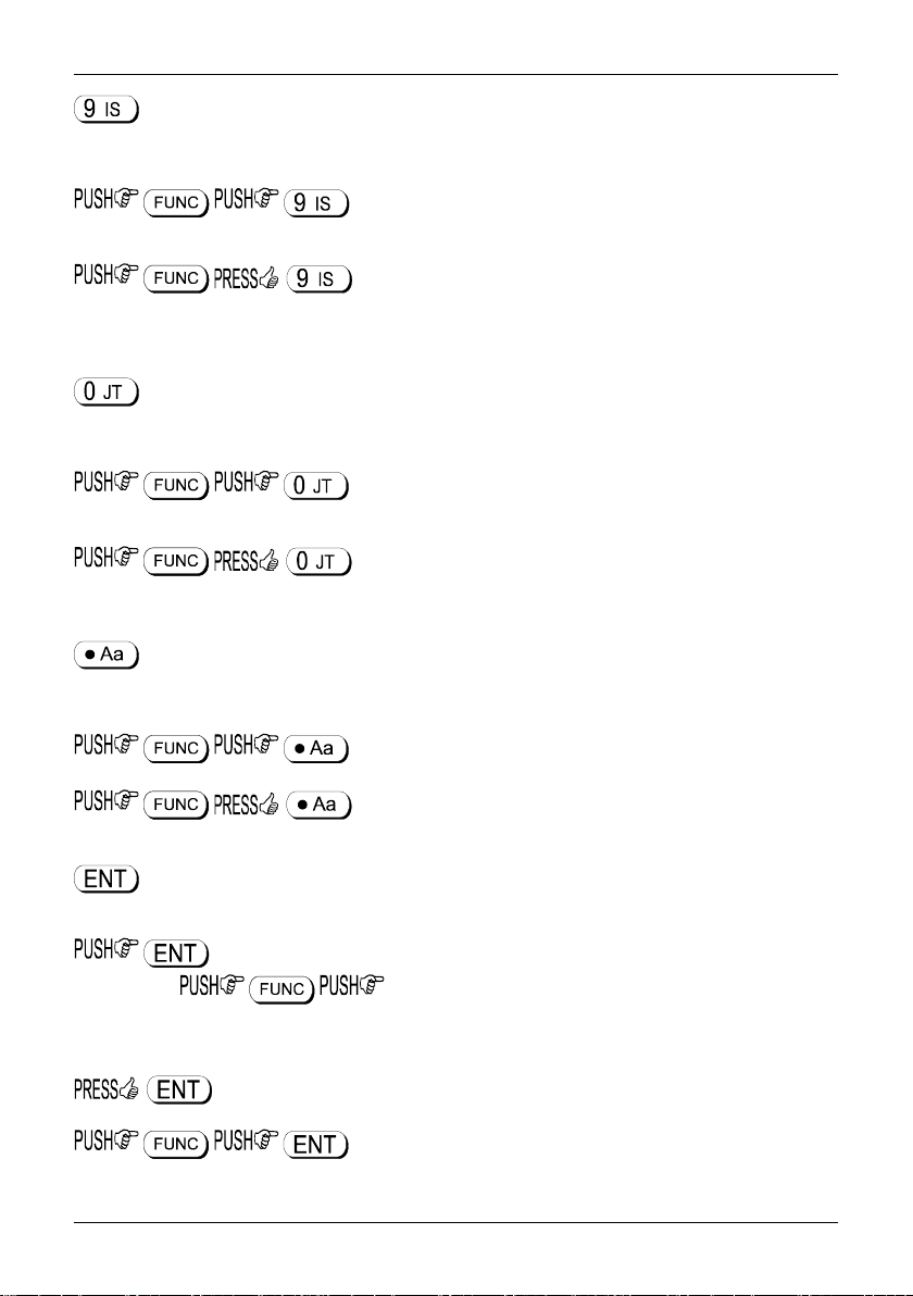
Numeric figure nine during frequency input. Selection of memory/scan bank “I” or “i” and search bank “I”
or “i” or “S” or “s”.
will delete the currently displayed memory channel during memory
read or scan.
accesses the delete menu where search banks, VFO pass
frequencies, memory banks, select channel tags, channel protect status & memory pass tags may be
deleted.
Numeric figure zero during frequency input. Selection of memory/scan bank “J” or “j” and search bank
“J” or “j” or “T” or “t”.
to toggle the AFC (Automatic Frequency Control) facility on/off,
the LCD legend “AFC” confirms selection.
to access the clone (copy between radio) menu. A special
RS232 male-male, pin-pin lead will be required.
Numeric decimal during MHz format frequency input. Used in memory and search as a CASE SHIFT
key to toggle between UPPER and LOWER case banks.
to access the frequency offset menu.
to access the sleep timer menu.
Used as an ENTER key to accept data entry.
during VFO operation to write the current frequency to QUICK MEMORY where the
key sequence recalls quick memory. The keys may be used to
cycle through the quick memories, the LCD legend “” indicates when a quick memory has been
recalled.
to enter the current frequency in to one of the 1,000 memory channels.
to access the text search menu.
14
Section 1-5-3
1-5-3 Important controls
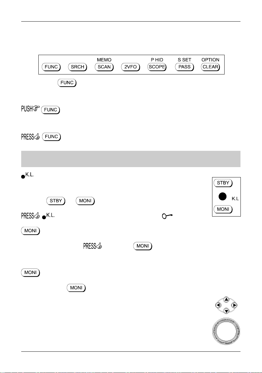
The bottom row of seven keys are fundamental in the operation of the AR8600. The SCAN, SEARCH
and VFO functions are actioned via this set of keys along with the FUNC and CLEAR operations.
FUNCTION KEY
The function (shift) key (located on the left hand side) is used to select the second function of keypad
facilities.
to toggle the function status on/off. A solid reverse legend LCD “FUNC” indicates
when function shift is in operation. The function status is terminated automatically in the normal course
of entry.
to initiate double-shift which is used in certain menus as a short-cut. The reverse
“FUNC” legend flashes when double-shift is engaged.
Note: When the “FUNC” legend is displayed in VFO mode, the tuning speed will be
increased to assist rapid frequency change using the arrow keys and main dial.
The KEY LOCK is intentionally small to reduce the chances of accidental operation. Key
lock is useful when you do not wish an important frequency to be lost or the AR8600 to be
incorrectly set to a different frequency. The key lock status is not deactivated by switch
off / on, the and keys are not affected by key lock.
to toggle the key lock on /off, an LCD key symbol “ ” indicates status.
The MONITOR key is used to force the squelch open so that you may manually intervene to ensure that
no weak signals are missed. and hold the key to defeat the squelch control (saves
turning the squelch control fully anti-clockwise then back to threshold position).
When the “DUP” legend is displayed during frequency offset or VFO SCAN (DUPLEX) operation, the
key forces the AR8600 to switch to the alternative frequency.
In SCOPE mode, the key enables the reception of the marker frequency.
MAIN DIAL
This large rotary control is intended to be rotated using your fingers and thumb or by
placing your thumb on the edge and rotating using a circular movement. Primarily this is
the tuning control, clockwise rotation tunes the AR8600 upward in frequency and anticlockwise rotation tunes downward in frequency using the selected tuning step size.
When the “FUNC” legend is displayed, the tuning speed will be increased. The main dial
is also used to move between menus and manipulate input through menus (generally
mimicking the arrow keys).
15
Section 1-5-3, 1-6, 1-6-1
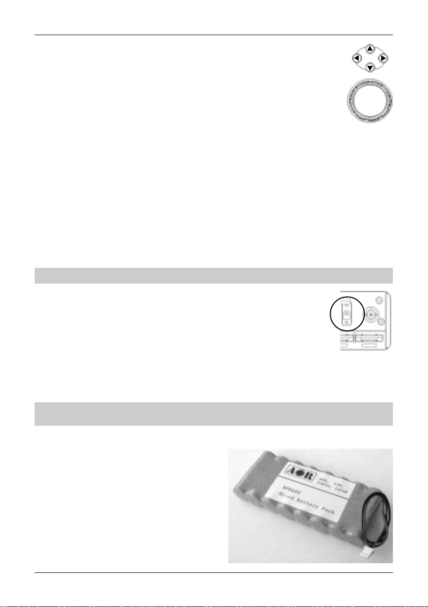
ARROW KEYS
The arrow keys are laid out as a group of four keys (up, down, left and right).
This format is particularly convenient being placed directly above the main dial.
The right arrow key is used as a backspace when entering frequency via the keypad.
Also selects bank in memory read mode, moves the cursor position (especially during
text input), tunes the receiver and changes values in menus.
The left arrow key selects bank in memory read mode, moves the cursor position (especially during text
input), tunes the receiver and changes values in menus.
The up arrow key increments to next memory channel in memory read mode, tunes the receiver in VFO
mode, selects menu items, changes values in on-screen menus and forces scan & search to resume
when stopped on a busy channel.
The down arrow key increments memory channel in memory read mode, tunes the receiver in VFO
mode, selects menu items, changes values in on-screen menus and forces scan & search to resume
when stopped on a busy channel.
Note: Ensure that the arrow keys are operated cleanly and one at a time.
1-6 Power supply
The AR8600 is designed for operation using a good quality regulated d.c. supply of 12
to 14V, which should be capable of supplying 1A. Never connect the AR8600 directly
to the a.c. supply.
The d.c. input socket uses a mini 2.1mm power connector. This connector is configured CENTRE
POSITIVE, the chassis of the receiver is at negative ground. If a power supply has been provided with
the AR8600 (depending upon world market area), it is pre-wired and provides a nominal 12V d.c. output
with suitable connectors being fitted as standard for the a.c. power input and connection to the AR8600.
SAFETY NOTICE - Always disconnect the power supply from the a.c. socket when
not in use.
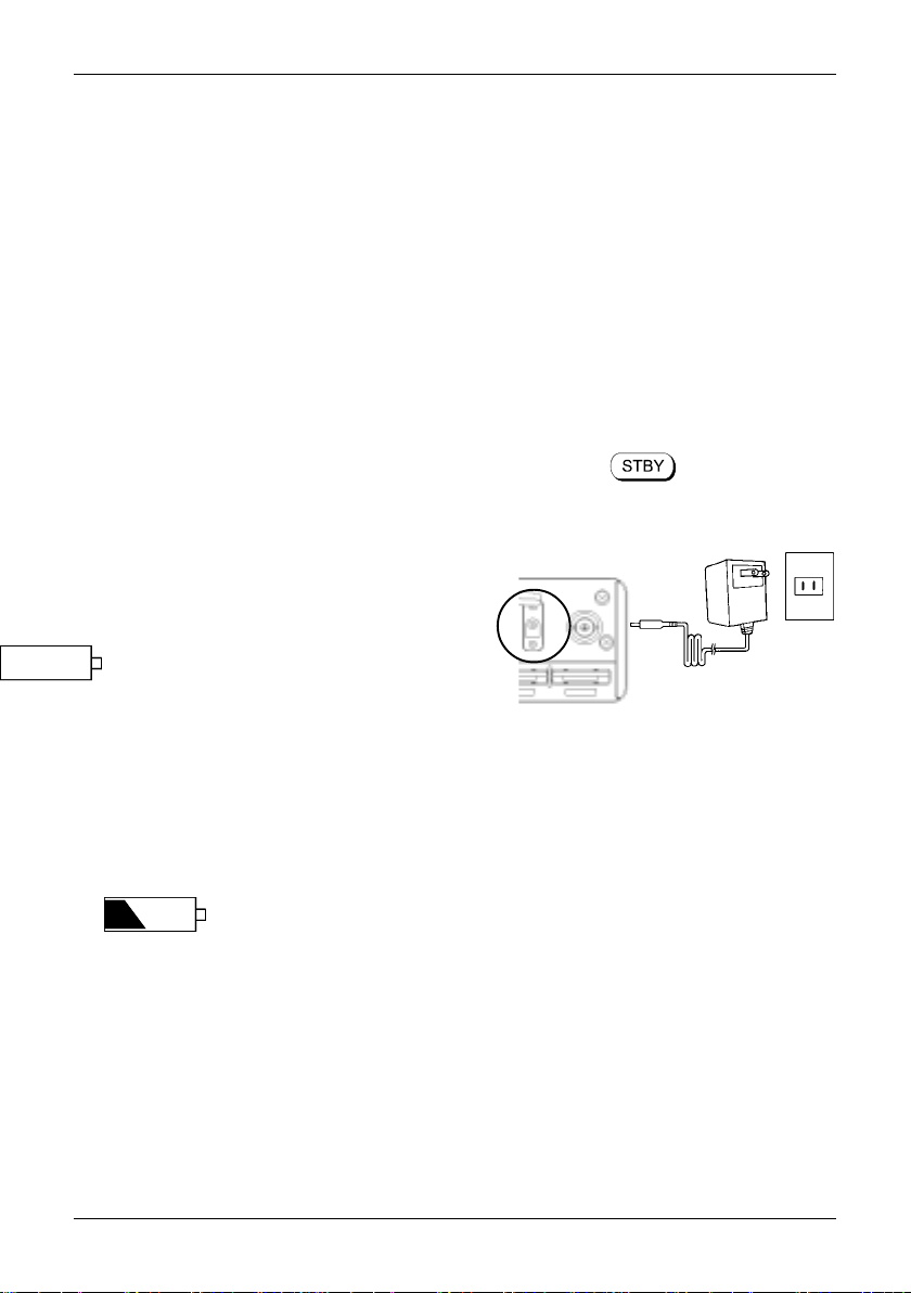
1-6-1 Optional internal battery
(BP8600)
The AR8600 has the provision for fitting a dedicated
internal NiCad rechargeable battery pack BP8600.
This pack comprises of 8 x AA NiCad high capacity
700mAhr sealed in a shroud with suitable connecting
cable and plug. The BP8600 is primarily intended for
emergency use or for applications away from an
alternative power supply. Fitting and removal of the
optional BP8600 is recommended to be carried out in
a workshop... once fitted, the batteries must be used
16
Section 1-6-1, 1-6-2
on a regular basis, if you are not going to use the AR8600 with the BP8600 for extended periods
(several months), it may be worth considering removing the batteries from the radio (to prevent the cells
deteriorating). It is most important that they are charged before placing them into storage and reusing
them within at least three months, ideally NiCads should be fully cycled not less than once every month
after they have been placed into use, always charge NiCads before placing them into storage.
These BP8600 is not charged at the factory before shipping, so you will need to charge it for 48 hours
before use. Dry cells such as Alkaline or Zinc / Manganese cannot be used, the AR8600 charging
circuit is not designed to recharge dry cells or NiMHi batteries.
Fitting batteries
The optional BP8600 battery pack must be fitted in a workshop.
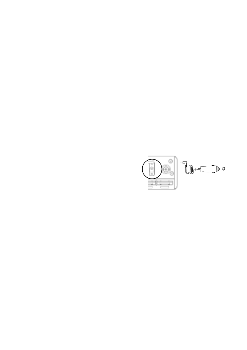
1-6-2 Charging the optional BP8600 battery
The optional BP8600 is intended to be charged while inside the AR8600 while connected to an external
12V d.c. power supply. Switch the AR8600 to STANDBY by pressing the key for more than
one second (or switching off the AR8600 using the PWR/VOL control). It will take 48 hours for the
BP8600 to fully charge, the BP8600 will not successfully charge when the AR8600 is in operation.
The AR8600 will provide around 2 hours of continuous
operation with one third volume and constant reception
with the backlight switched off. The operational time
between charges will be dependant upon volume level
and operating parameters, the power save facility will
also extend operating time.
If connected to an external power supply, the AR8600
many be used for continuous operation regardless of
the charge status of the NiCad battery (the charge
current being at a very low level).
When the NiCads near discharge, three states will be encountered:-
1. A battery symbol will appear in the extreme top right of the LCD a couple of minutes before the
NiCads completely discharge. The operational cut-off point is difficult to determine making advance
warning brief. The legend will have one diagonal bar representing minimal charge left.
2. The LCD battery legend will become an empty outline... operation will cease almost immediately.
3. The NiCads will expire and the set will power off (the VFO frequencies and last stored memory
may be lost). Connect a 12V d.c. power supply to continue operation or recharge the battery.
17
Section 1-6-3, 1-6-4
1-6-3 Battery considerations
The optional BP8600 battery is not factory charged. When the BP8600 has been fitted, charge the
battery for 48 hours. After this time the NiCads should never be left in a flat condition or internal
filaments will form (inside the NiCads) shorting its terminals rendering it useless. If you are not going
to use the NiCads for a few months, charge them before placing them into storage. NiCads have a
memory effect, for longevity, once a month flatten them completely then fully charge them again.
Avoid excessive ‘topping up’, when possible, it is best to charge NiCads when they are totally flat.
If you have not used the cells for a long time, it may be difficult the battery to accept a charge, to help
‘bring them back to life’, first ensure they are COMPLETELY discharged then charge for a longer period
of time, perhaps 72 hours. It is common practice to force complete exhaustion by leaving the squelch
open and volume set to half until the AR8600 stops working, carry this out once a month to ensure best
battery longevity.
Do not continuously charge (forever) without some use of the radio, this may shorten the life span of the
NiCads. Although the charge current is of a very low level, where batteries are concerned, permanent
charging leads to a small chance of explosion due to the build up of heat. If you intend permanently
using the AR8600 from an external power supply, remove the BP8600 battery. Do not short NiCads as
they can provide high current levels. The BP8600 will typically provide around 300 charge / discharge
cycles.
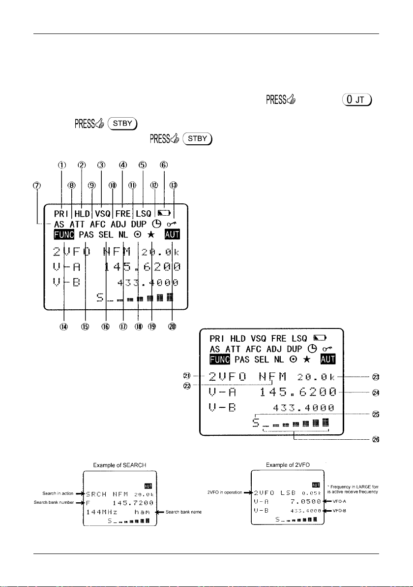
1-6-4 Cigar lighter lead
It is possible to power the AR8600 from a vehicle using the
optional DC8600 cigar lead, this will power the AR8600 in
exactly the same manner as the a.c. power supply (except
that it is connected to a vehicle 12V d.c. supply). Ensure
that the vehicle has a 12V d.c. battery, do not connect to a
truck / H.G.V. 24V battery.
The tip on the cigar plug must be positive (+), the vehicle must be negative ground. A 1A fuse should be
fitted inside the cigar lead, should this fuse blow for some reason, ensure it is replaced with the correct
type. Avoid short circuits.
Switch off the AR8600, connect the cigar lead to the AR8600 12V d.c. input socket THEN connect the
cigar plug to the vehicle and switch the AR8600 on. It is advisable to switch the AR8600 off when
starting the vehicle as the starter motor often causes power surges. Some vehicles require their ignition
to be ON for the cigar socket to operate.
18

Section 1-7
1-7 IF output and Spectrum Display Unit (SDU5500)
The rear panel has a 10.7MHz i.f. output designed to drive the SDU5500 optional Spectrum Display Unit.
The AR8600 must be enabled in order to provide the i.f. output, this operation should be carried out in a
workshop. The WFM circuit of the AR8600 becomes permanently active to achieve a wide bandwidth
(irrespective of receive mode employed), however the usable bandwidth remains smaller than the total
10MHz provided by the SDU5500. The i.f. output varies depending upon receive frequency and receive
mode.
The SDU5500 provides an excellent tool
for locating elusive transmission with a PEAK
capability to ‘freeze’ the briefest of transmissions
for later measurement of frequency and level after
the event. A free supporting PC software
package provides a virtual on-screen display of
the SDU5500 with AVI video recording to disk so
that events may be replaced at varying speeds for
historic analysis.
The firmware of the SDU5500 is FLASH upgradable. It may be necessary to upgrade the SDU5500
firmware to support for the AR8600, other models and new features may be added to the SDU5500
in the same manner. Details are published on the AOR web site including the HEX data and full
instructions (plus computer control), no workshop equipment is required for firmware update and you
do not need to remove the case of the SDU5500, all data is sent via the RS232 connection via a
terminal program.
19
Section 2, 2-1
(2) Making the AR8600 ready for operation
2-1 LCD (Liquid Crystal Display)
All relevant operational information is provided via the central LCD. To see all the available LCD
legends, and to test the LCD, an LCD test routine has been provided. and hold the
key then switch the AR8600 on, (then turn the PWR/VOL control clockwise to provide power or if already
switched on . When the sign-on message has been displayed all LCD graphics will
be displayed. To exit the LCD test . The LCD contrast is adjustable using the
configuration menu as is the rear LCD & keypad illumination.
1 Priority
2 Search hold / band scope peak hold
3 Voice squelch
4 Free search / scan
5 Level squelch
6 Low battery (if optional BP8600 is fitted)
7 Auto store
8 Attenuator
9 Automatic Frequency Control
10 Step-adjust
11 Duplex
12 Sleep
13 Key lock
14 Function
15 Pass (lockout)
16 Select scan
17 Noise limiter
18 RS232 remote
19 Band scope peak
search / quick memory
20 Auto-mode
21 Operating mode
(2VFO, SRCH, SCAN etc)
22 Receive mode
23 Tuning step size
24 Active receive frequency
25 Squelch open legend
26 Signal meter
Typical examples of LCD:-
20
Section 2-1, 2-2, 2-3
2-2 Connect the aerial (antenna)
Two aerials are supplied with the AR8600:
BNC mounted whip aerial with swivel
BC ANT - MW bar aerial
For general reception on the VHF/UHF bands, connect the
supplied whip aerial to the BNC socket on the rear panel of
AR8600. This is a bayonet connector, line up the slots, press
down firmly and twist clockwise, the guides will position, then let go.
Position the right-angle and swivel for the most convenient position with the whip
generally pointing upward. A different (external) aerial can easily be fitted once you have
established that the AR8600 is operating correctly and you are familiar with operation.
If you wish to monitor MW (Medium Wave bands), plug in the BC ANT - MW bar aerial. The BC ANT
If you really press very hard, it is
possible to force the connector in
backwards... the BC ANT will not operate
if connected backwards!
slot is located centrally on the
rear panel. With the ‘AOR’
logo of the BC ANT facing
upward, insert the aerial into
the slot, no force
is required... if you feel
resistance, you are probably
trying to insert it upside-down!
The BC ANT is asymmetrical.
With the longer arm of the bar facing
to the right (grooves to the bottom).
2-3 Connect power
Connect the power to the AR8600 d.c.
socket as detailed in section 1-6 of this
manual. Either a regulated d.c. power
supply 12 - 14V with capacity of 1A may be
used or a suitable connection to a vehicle
cigar lighter plug, do not connect to a 24V
system such as a HGV. If the optional
BP8600 battery is fitted, refer to section
1-6-1 of this manual.
21
Section 2-4, 2-4-1, 2-4-2, 2-4-3
2-4 Keypad and knobs... what you need to know ‘most’
Several of the keys have special characteristics, a summary was given in section 1-5-1 of this manual
where it was explained that several keys have two of three functions associated with them.
IMPORTANT Note: Make sure you understand the PASS (LOCKOUT / SKIP) operation
before using the PASS facility, this applies to the PROTECT facility too, make sure both
facilities are understood before you attempt to use them.
The list presented here represents ‘what you need to remember most’ ! Refer to section 1-5-1 of this
manual for the definition of and should you not understand the syntax shown here.
2-4-1 ENTER key
Used as an ENTER key to accept data entry.
to enter the current frequency in to memory (a quick memory facility is also available,
explained section 4-1 of this manual).
to access the text search menu.
2-4-2 FUNCTION key
The function (shift) key is used to select the second function of keypad facilities.
to toggle the FUNCTION (shift) on/off. An solid reverse legend LCD “FUNC”
indicates when function shift is in operation. The function status is terminated automatically in the
normal course of entry.
to initiate double-shift which is used in certain menus as a short-cut. The reverse
“FUNC” legend flashes when double-shift is engaged.
2-4-3 PASS key
This key needs special attention as it acts as select ON/OFF/DEFAULT toggle in various menus.
key to PASS (lockout) memory channels during memory read & scan mode and to
PASS (lockout / skip) unwanted frequencies in search mode.
in 2VFO mode to access the VFO PASS menu which extends to include the
SEARCH bank pass edit menu.
PRESS in 2VFO, SEARCH or SCAN mode to access the SELECT SCAN
edit menu.
22
Section 2-4-4, 2-4-5, 2-4-6, 2-4-7
2-4-4 CLEAR key
to abort entry via the keypad... if in doubt, to return to the previous
display menu or operating mode.
to select an option when an optional SLOT CARD is used.
and hold the key while powering on the AR8600 to soft reset the
microprocessor should the AR8600 appear to behave strangely... no memory contents will be lost.
2-4-5 MONITOR key
The MONITOR key is used to force the squelch open to manually intervene ensuring that no weak
signals are missed. and hold the key to defeat the squelch control (saves turning
the squelch control fully anti-clockwise then back to threshold position).
When the “DUP” legend is displayed during frequency offset or VFO SCAN (DUPLEX) operation, the
key forces the AR8600 to switch to the alternative frequency.
In SCOPE mode, the key enables the reception of the marker frequency.
2-4-6 KEY LOCK
The KEY LOCK is intentionally small to reduce the chances of accidental operation. Key lock is useful
when you do not wish an important frequency to be lost or the AR8600 to be incorrectly set to a different
frequency. The key lock status is not deactivated by switch off / on, the and keys are
not affected by key lock.
to toggle the key lock on / off, an LCD key symbol “ ” indicates status.
2-4-7 Standby key
The STANDBY key is used for every day switching on and off the AR8600. It is recommended
that the PWR/VOL on/off switch be used only to isolate power from the receiver prior to connection
and disconnection of the power lead... if the AR8600 is switched off using the PWR/VOL switch, the
current VFO data may be lost.
to switch the AR8600 on and off.
23
Section 3, 3-1, 3-2
(3) Basic manual operation of the receiver
The following information explains how to tune to a specific frequency, change receive mode etc.
Note: When the AR8600 is switched OFF USING THE STANDBY KEY, all VFO
data will be automatically stored into flash-ROM memory storage. No battery or capacitor is
required for memory backup. If the AR8600 is switched off using the PWR/VOL control prior to
use of the key, the VFO data may be lost. If the optional BP8600 battery is fitted and
becomes completely exhausted, the last stored memory channel or last VFO data ‘may’
be lost.
CURSOR
The CURSOR may apparently ‘go to sleep’ at times when menus are called. This is because of the
many tasks called by the microprocessor, it is simply doing something else at the time you call it. This
is particularly noticeable when recalling memory banks when only a few channels have been stored.
3-1 Switching On for the first time
Set the squelch control to the ‘mid point’ and rotate the PWR/VOL control to the ‘mid
point’, as you start to rotate the PWR/VOL control a ‘click’ will be heard as the power
isolation switch contact switches on. For future switching on and off, the
key. It is never a good idea to switch on any receiver with an earphone connected, there may be an
audible click when the unit is switched on or the volume may be accidentally set uncomfortably high.
In the default state, the LCD will show the opening message “WELCOME TO THE NEW
WORLD OF AR8600” across the first four lines, at the same time the microprocessor
generates the ‘boot up data’ required to control the receiver. When the key is
used, the opening message is bypassed.
In normal use, the squelch control should be rotated clockwise until the background noise
is just cancelled, this is known as ‘threshold’ and is the most sensitive setting for the
squelch control. Do not rotate the control too far clockwise or only the stronger local
signals will be heard. If you find setting the squelch control difficult, try removing the aerial
from the receiver.
Should you encounter problems in setting the volume level, the key to
momentarily defeat (open) the squelch so that a comfortable volume level may be set.
It is best to the key at this time to place the AR8600 in a known state of operation.
The condition of “VFO” (1VFO) or “2VFO” is generally referred to as manual mode. The “2VFO” legend
will be displayed in the upper left of the LCD to confirm selection.
Note: If the AR8600 has no data input via the keypad or other controls for 90 seconds,
some menus will time out and the AR8600 will return to its previous task just as if the
key had been operated.
3-2 2VFO twin VFO selection
The AR8600 receiver has a twin VFO system being identified as “V-A” and “V-B” on the LCD to the left
of the frequency readout. The term VFO historically means ‘Variable Frequency Oscillator’ and today
refers to a tuneable data store which contains frequency, mode, step, step-adjust, attenuator etc.
24
Section 3-2
In 2VFO mode both VFO frequencies are displayed in parallel format on the LCD, one above the other.
The ‘active’ VFO (the one which is currently receiving) is displayed using a large font centrally on the
LCD, the ‘standby’ VFO is shown on a lower line using a smaller font size (when using VFO SCAN it is
possible for the lower line frequency to be active, in this case a larger text size is employed for clarity).
the key to first select ‘VFO mode’ (should the receiver be scanning or searching etc).
Each time the key is pushed VFO “V-A” and VFO “V-B” alternate between active and standby.
The first time you enter a frequency via the numeric keypad, it is best to the key to
place the receiver in a known state of operation. the key so the “V-A” becomes the
active VFO (upper and largest of the two frequency readouts). This condition is referred to as ‘2VFO’
mode with VFO-A active and VFO-B as standby. If you find the twin frequency display confusing,
or use the key sequence
(while no signal is present) so that only a single frequency readout is displayed, this is referred to as
‘1VFO’ mode. Both 1VFO and 2VFO modes may be referred to simply as VFO mode or manual mode.
25
Section 3-2, 3-3
Transfer to active VFO
When the AR8600 has stopped on an active frequency in memory read, scan or search mode, use the
key sequence to transfer the frequency to the active (upper VFO).
The AR8600 will revert to 2VFO mode where the frequency may be monitored.
3-3 Entering a frequency using the numeric keypad
While in VFO mode, enter the required frequency using MHz format followed by .
Example of frequency entry 80.8 MHz
There is no need to key in the trailing zeros to the right of the decimal point as they are automatically
added by the microprocessor.
If keying in a whole MHz such as 118.000 MHz there is no need to key in either the decimal point or
trailing zeros, they are all added by the AR8600 microprocessor.
Example of ‘MHz round number’ frequency entry for 808.000 MHz
While keying in frequency data, the bottom line of the LCD displays “FREQ SET” to indicate what sort of
data input the AR8600 is expecting. Similar helpful messages are displayed at other times during data
input.
Example of frequency entry 954 kHz (0.954 MHz)
The frequency of 954 kHz is equivalent to 0.954 MHz. When entering frequencies below 1 MHz, there
is no need to proceed the decimal point with a zero as this is added by the microprocessor during
frequency entry then removed when the key is pushed to ensure the display appears neat
and tidy.
You will note that frequencies below 3.0 MHz (3000 kHz) will be automatically displayed in kiloHertz
format (the letter “k” will be displayed to the right of the frequency readout) and the decimal point
26
Section 3-3, 3-4, 3-5
displayed to the right of the kHz position. This is to ensure easy recognition of short wave frequencies
which are often listed as ‘kHz’ in frequency guides.
If an attempt is made to enter an ‘out of range’ or invalid frequency (such as 2345 MHz or 0.09 MHz) the
error beep will sound (if beep is enabled) and the LCD returns to the previous frequency prior to
frequency input. Acceptable input range is 0.1 MHz to 2040 MHz.
Note: If you pause during frequency input for more than 90 seconds, the menu will time out
and the AR8600 will return to its previous task just as if the key had been operated.
Aborting frequency input
If for some reason you do not wish to complete the frequency data input, before
completing the input sequence with
3-4 Correcting frequency input
Should an error be made while entering frequency data (by pressing the wrong numeric key), it may be
corrected using the BACKSPACE facility. This facility enables rapid correction of errors prior to the
completion of entry by the enter key.
Example of frequency data correction while keying 433.250 MHz
then (as if you have made a mistake)
, the number “7” clears from the LCD
to finalise the correct entry.
3-5 Changing frequency using the and keys
The and keys provide a convenient method of frequency change.
The speed at which the receiver steps up or down depends upon the STEP SIZE which is default to
AUTO. In AUTO the step size, receiver mode etc is taken from the factory pre-programmed band plan
but may be overridden at any time.
Examples of tuning step include: 0.05 kHz (50 Hz), 0.1 kHz (100 Hz), 0.2 kHz (200 Hz), 0.5 kHz (500
Hz), 1.00 kHz, 2.00 kHz, 5.00 kHz, 6.25 kHz, 8.33 kHz, 9.00 kHz, 10.00 kHz, 12.50 kHz, 20 kHz, 25.00
kHz, 30 kHz, 50 kHz, 100.00 kHz. The tuning step size may also be programmed in multiples of 50
Hz (via the keypad) so that unusual step sizes other than stated are possible.
the key to tune the receiver upward in whichever step size is selected, use the to tune the
receiver downward in frequency. You may and hold either key to continuously tune the
receiver in whichever direction is desired, tuning will stop when the key is released.
27

Section 3-5, 3-6
Note: When tuning, reception may occasionally be momentarily
interrupted while tuning and the “S” squelch legend will flash as tuning
progresses, some noise may accompany tuning, this is normal.
Fast tuning
The and keys may be used to tune the receiver at a rate TEN TIMES
FASTER than the selected step size. This means that when a step size
of 25 kHz is selected, tuning will be in 250 kHz steps, this provides a
convenient method to quickly tune up and down frequency bands.
Note: Be aware that when auto-mode is selected and a tuning
step change has automatically taken place, one PUSH up or down
may take several pushes to arrive back to the starting place again.
1 MHz tuning
While the “FUNC” legend is displayed (achieved by a of the key, again to
deactivate as a toggle), the tuning rate for the and keys is 1 MHz per increment.
3-6 Changing frequency using the main dial
While in VFO mode, the active VFO frequency may be ‘tuned’ in a similar way to a domestic receiver or
other specialist receivers using the rotary tuning main dial which is mounted on the right hand side of
the front panel. You may rotate the control between your fingers or place your thumb near the edge and
rotate using a circular motion... use whatever is most comfortable.
This method of frequency selection is the most traditional approach to locating signals particularly on
the short wave and medium wave bands. It provides an easy method to locate new or previously
unknown frequencies or to check activity within certain frequency bands such as amateur or short wave
broadcast. The rotary tuning main dial provides the very best ‘user interface’ with the AR8600 especially
for USB, LSB and CW listening.
Rotating the main dial ‘clockwise’ increases frequency while
rotation ‘anti-clockwise’ decreases receive frequency.
The speed at which the main dial tunes the receiver depends upon the STEP SIZE which is default to
AUTO. Examples of tuning step include: 0.05 kHz (50 Hz), 0.1 kHz (100 Hz), 0.2 kHz (200 Hz), 0.5 kHz
(500 Hz), 1.00 kHz, 2.00 kHz, 5.00 kHz, 6.25 kHz, 8.33 kHz, 9.00 kHz, 10.00 kHz, 12.50 kHz, 20 kHz,
25.00 kHz, 30 kHz, 50 kHz, 100.00 kHz. The tuning step size may also be programmed in multiples of
50 Hz (via the keypad) so that unusual step sizes other than stated are possible.
While the “FUNC” legend is displayed (achieved by a of the key, again to
deactivate as a toggle), the tuning rate for the main dial is TEN TIMES FASTER than the selected step
size. This means that when a step size of 10 kHz is selected, tuning will be in 100 kHz steps, this
provides a convenient method to quickly tune up and down frequency bands.
28
Section 3-7, 3-7-1, 3-7-2
3-7 Changing receive mode
Due to the necessities of signal bandwidth, channel occupancy and transmission efficiency, different
receive modes are used by various services. In addition to this the specification for tuning step and
receive mode are allocated by departments of Governments following International discussions so are
not consistent throughout the world. For this reason, it is necessary to change receive mode in order to
monitor various transmissions.
For your convenience, receive mode and tuning step size have been pre-programmed into the AR8600
auto-mode bandplan data at the factory to simplify operation of the receiver, especially while you
familiarise yourself with all the facilities. Should you wish, the defaults may be manually overridden at
any time so that you may select an alternative receive mode and tuning step on any frequency.
3-7-1 Auto-mode selection
When auto-mode is in operation (so that receive mode and tuning
step size are automatically selected for you by the AR8600
microprocessor), the reverse legend “AUT” is displayed toward
the top right of the LCD.
To activate auto-mode or reconfirm its selection while in VFO
mode,
Alternatively “AUTO” may be selected from the “MODE SET”
menu accessed with the key sequence
The key acts as a short cut to “AUTO”, alternatively use
the main dial or keys. When the reverse “AUTO” legend has
been selected, to accept the data input. The
LCD will revert to VFO mode with the “AUT” legend confirming selection.
Note: Auto-mode is cancelled as soon as the receive mode, tuning step or other
related data is changed. Remember that auto-STEP and auto-MODE are linked, reselect
AUTO-MODE if either have been adjusted and you require the auto bandplan selection.
3-7-2 Receive mode selection menu
Any receive mode may be selected at any frequency within the receiver’s frequency coverage.
To access the receive mode menu , the following modes are
available: AUTO, WFM, NFM, SFM, WAM, AM, SAM, USB, LSB, CW. Use the main dial or
keys to make selection, the key acts as a short cut to “AUTO”. To accept the selection
As a further short cut to AUTO MODE, . The reverse LCD legend
“AUT” confirms selection.
29

Section 3-7-2
With regard to receive mode, generally speaking the following modes will apply:
AUTO
Receive mode and tuning step will be selected automatically using the pre-programmed auto
bandplan data.
WFM
Wide band Frequency Modulation - used by VHF and UHF broadcast stations as excellent audio quality
is available due to the relatively wide frequency bandwidth employed. Used only for local services such
as VHF Band-II stereo (received as mono on the AR8600) and UHF TV sound channels.
When listening in VERY strong signal locations especially when using an external aerial, adjacent
channel interference may be observed due to the wide nature of the IF filters. Should interference
be encountered, use the attenuator to reduce signal strength or swap to the standard telescopic whip
aerial.
NFM
Narrow band Frequency Modulation - this provides high quality communication for relatively short
distance operation. NFM uses a greater frequency bandwidth than other point-to-point modes such as
SSB so is less efficient.
NFM is the most common mode used above 30 MHz with the exception of the airbands (which use AM).
NFM is widely used on the VHF bands: VHF Marine band, 2m amateur Band (145MHz), 70cm amateur
band (433 MHz), PMR (Private Mobile Radio) and utilities.
In the absence of a signal, the background white noise may appear quite loud. For ease of listening the
squelch control should be rotated clockwise until the background noise just disappears, this should be
carried out when no signal is present. The point where the background noise is cancelled is known as
‘threshold point’. Do not advance the squelch control more than necessary or the receiver will appear to
be desensitised and weaker signals will be missed.
SFM
Super Narrow band Frequency Modulation - this mode is specific to the AR8600. Essentially this is the
same mode as NFM but uses a narrower IF filter for added selectivity when monitoring crowded bands
such as PMR utilities.
WAM
Wide Amplitude Modulation - this mode is specific to the AR8600. It is essentially the same as AM but
uses a wider IF filter, particularly useful for monitoring parasitic airband transmissions when ‘repeater
transmissions’ are employed. Provides good broadcast quality for MW (medium wave band) listening to
strong local signals when adjacent channel transmissions are not encountered.
AM
Amplitude Modulation - Used by broadcast services throughout the world on medium wave and short
wave. AM is also used by VHF civil airband, UHF military airband and some PMR (Private Mobile
Radio) and utility services.
NAM
Narrow Amplitude Modulation - this mode is specific to the AR8600. It is essentially the same as AM
but uses a narrower IF filter for added selectivity when monitoring crowded bands such as short wave.
Due to the narrower bandwidth employed, the audio quality will be compromised.
USB
Upper Side Band - is a form of Single Side Band (SSB). USB is used commercially and by radio
amateurs on frequencies above 10 MHz (below 10 MHz radio amateurs tend to use LSB to assist the
separation of commercial and amateur users on traditionally shared bands, this prevents them from
attempting to communicate with each other… which is prohibited).
30

Section 3-7-2, 3-8
All long range shipping and oceanic air traffic (as well as long range military aircraft) use USB. DATA
modes such as RTTY, SITOR, PACKET, FAX etc may be resolved using USB.
SSB is a very efficient method of transmission as the unwanted second sideband and carrier have been
removed. This allows the full transmitter power to be employed in conveying useful information within
the wanted sideband. As a result, greater distances are possible on SSB with a smaller frequency
bandwidth being required than most other receive modes.
The AR8600 uses true carrier re-insertion and a dedicated SSB i.f. filter so that voice becomes
intelligible. However due to the complexities of SSB, audio never sounds 100% natural, like all SSBequipped receivers, the AR8600 may sound a little ‘robotic’ but you soon get used to SSB receivers.
Small tuning steps of 50 Hz or 100 Hz should be used for tuning in USB and the other similar modes
LSB & CW.
The AR8600 is a wide band receiver and as such cannot offer the receive performance of a
dedicated short wave receiver such as the AOR AR7030, this is mainly due to the limitation of
size. The AR8600 will however provide adequate results for oceanic, ship to shore, amateur band
and general broadcast listening etc.
The SSB frequency display is not offset (like some other units), this is good for referencing to frequency
booklets and data bases. However being such a compact wide band receiver, it will not be unusual for
the SSB display to be a few hundred Hz off frequency when listening to known frequencies such as
VOLMET (airband weather forecast service)... this is considered normal.
LSB
Lower Side Band - The same comments apply as for USB. By convention, radio amateurs use LSB
below 10 MHz.
CW
Continuous Wave - Often referred to a Carrier Wave or Morse code ‘dots and dashes’. Commonly
used on the short wave bands by radio amateurs toward the lower end of each band allocation. Some
commercial use is still made by shipping etc although its use is being phased out due to the introduction
of automated stations.
3-8 Changing tuning STEP size
The specification for channel occupancy, step (separation) and mode are decided by and allocated by
departments of Governments following International discussions.
Not surprisingly the allocation of frequency bands are not the same all over the world and channel
separation (step) varies from band to band. As an example, the channel separation (step) for the
medium wave band in Europe is 9 kHz while in the U.S.A. it is 10 kHz.
For the above reasons it is necessary to alter the STEP size according to local bandplan conventions.
The AR8600 has been pre-programmed at the factory with all the bandplan data (specific to each market
area) so that the AR8600 will automatically select the appropriate step size and mode for the frequency
chosen. This greatly simplifies operation of the receiver while you are familiarising yourself with all the
facilities.
The pre-programming of step size may be manually over-ridden so you may choose alternative settings
at will or when band plans are updated.
31

Section 3-8
Should you wish to change the default tuning step size .
The third main text line of the LCD will display the current default
size (perhaps “25.00” kHz). If the reverse LCD legend “AUT”
displayed in the upper right corner of the LCD, this indicates that
AUTO MODE / STEP is currently selected.
The bottom line of the LCD displays the legend “STEP SET” to
indicate that the AR8600 is inviting you to change the step size.
Use the main dial or and keys to select the required step size.
The list is as follows: 0.05 kHz (50 Hz), 0.1 kHz (100 Hz), 0.2 kHz
(200 Hz), 0.5 kHz (500 Hz), 1.00 kHz, 2.00 kHz, 5.00 kHz, 6.25
kHz, 8.33 kHz, 9.00 kHz, 10.00 kHz, 12.50 kHz, 20 kHz, 25.00 kHz,
30 kHz, 50 kHz, 100.00 kHz.
To accept the displayed tuning step size ,
the LCD will revert to its previous display.
Note: The frequency step of 8.33 kHz has been included
for compliance with the new VHF airband allocation, it has
been correctly implemented as eight-and-one-third kHz so that
no compound error arises (i.e. the last digits display 33, 66, 00).
The tuning step size may also be programmed in multiples of 50 Hz (via the keypad) so that unusual
step sizes other than stated are possible. The acceptable step size range is 0.05 kHz (50 Hz) to
999.95 kHz in 50 Hz steps.
When the desired step size has been entered,
to accept the new step size. If you attempt to input an invalid step
size, the error beep will sound (presuming that the beep facility is
enabled) and the incorrect input will be ignored.
* Active frequency must be divisible by step size *
There is just one small point to bare in mind, the active frequency
must be divisible by the step size... in 99% of cases they will be.
However, should you start experimenting with different step sizes
you may notice the active frequency change automatically to
the nearest multiple of step size as the AR8600 calculates
automatically for you, there is no need to carry a calculator!
For example, select 118.000 MHz then select a 9 kHz step size:
choose “9.00” using the main dial then
The receive frequency will currently be displayed as 118.000 MHz but once the main dial has been
used, the displayed frequency will be corrected to 117.9990 or 118.0080 MHz (depending upon the
direction of tuning) both of which are the closest multiple of 9 kHz to 118 MHz.
32

Section 3-8, 3-9, 3-9-1
The display doesn’t correct immediately upon frequency entry to allow you to enter the ‘STEP-ADJUST’
menu to change the step size and step-adjust in order to help track unusual band plans.
Note: AUTO-STEP, STEP-ADJUST and AUTO-MODE are linked to the pre-programmed
bandplan data. When one of the parameters is changed from the default “AUTO” the bandplan
will be ignored.
To reinstate AUTO step size, the receive MODE must be returned to “AUTO” using the “MODE SET”
menu or by using the key sequence
3-9 STEP-adjust
The AR8600 provides a powerful feature to enable accurate
following of unusual band plans. When active, the “ADJ” legend is
displayed top-centre of the LCD.
Step-adjust is used when the receiving frequency is not divisible
by the step size in use (It is possible that step-adjust has been
programmed into the auto-mode bandplan data for some world
market areas). Therefore step-adjust is useful for certain band
plans such as cellular which in some areas starts as 917.0125 MHz then increments in 25 kHz steps.
Another example is the CB allocation in certain areas which starts at 27.60125 MHz then increments in
10 kHz steps. Often just a HALF STEP is required but more exotic band plans can be tracked.
Step-adjust may be factory pre-programmed into the bandplan data (you may override this). It is also
possible to store the step-adjust data into memory channels and search banks.
3-9-1 Automatic calculation of step adjust
The AR8600 can calculate the required step-adjust, simplifying its use.
Example 1: Assume that you wish to tune from 148.010 MHz in 20 kHz steps (i.e. 148.010, 148.030,
148,050, 148.070, 148.090 etc). When manually tuning, the AR8600 would normally correct the
frequency display to read 148.020 then step upward in 20 kHz steps. Tuning back downward will skip
148.010 MHz (the starting point) as the original frequency was not divisible by step size… it was
offset by +10 kHz. Usually the frequency must be divisible by the tuning step size. However, the
STEP-ADJUST facility is used to address this situation.
With the above example of 148.010 MHz with 20 kHz steps in mind, while in VFO mode, key in the start
frequency of 148.010 MHz
33

Section 3-9-1, 3-9-2, 3-9-3
Access the STEP menu using the key sequence
. Use the main dial to
select a step size of 20 kHz (do NOT press enter!).
to access the STEP-ADJUST menu.
Accessing this menu will activate the step-adjust facility,
the “ADJ” legend will be displayed on the LCD
to confirm selection. You will note that the
calculated step adjust value is displayed on the
bottom of the LCD as “ADJ+ 10.00” representing
a positive offset of +10 kHz with a step size of
20 kHz. to accept the
displayed data.
The display will return to VFO mode with 148.010
MHz displayed. The main dial will now correctly
follow the required bandplan.
3-9-2 Cancelling step-adjust
There are two ways to cancel step-adjust
1. Access the STEP menu. , the step-adjust data will be
immediately displayed along with step size. to remove the step-adjust data
from the display, the “ADJ” legend will be removed from the LCD. to accept
the changes. Step-adjust will be cancelled.
2. Presuming that you have manually selected step-adjust (step-adjust has not been set by the
auto-mode bandplan), reselect AUTO-MODE which will reinstate the auto-mode step size, step-
adjust, frequency offset and receive mode. . The “ADJ”
legend will be removed from the LCD and the auto-mode “AUT” legend will be displayed.
3-9-3 Manual setting of step-adjust
The AR8600 usually correctly ‘guesses’ what step-adjust you require, often this is a half step but manual
intervention is possible!
Example 2: Assume that you wish to tune from 58.445 MHz in 15 kHz steps (i.e. 58.445, 58.460,
58.475, 58.490, 58.505 etc). When manually tuning, the AR8600 would normally correct the frequency
display to read 58.455 then step upward in 15 kHz steps. Tuning back downward will skip 58.445 MHz
(the starting point) as the original frequency was not divisible by step size… it was offset by +5 kHz.
Usually the frequency must be divisible by the tuning step size.
34

Section 3-9-3
However, the STEP-ADJUST facility is used to address this situation.
With the above in mind, 58.445 MHz with 15 kHz steps in mind, while in VFO mode, key in the start
frequency of 58.445 MHz
Access the STEP menu using the key sequence . 15 kHz is not a
standard size provided by rotating the main dial so key in the required 15 kHz step size.
(do NOT press enter!). to access the
STEP-ADJUST menu. Accessing this menu will activate the step-adjust facility, the “ADJ” legend will be
displayed on the LCD to confirm selection. You will note that a calculated step-adjust value is displayed
on the bottom of the LCD as “ADJ+ 7.50” representing a positive offset of +7.5 kHz with a step size of
15 kHz… the AR8600 often assumes that you require a half step. However when looking at the
requirement the required offset is actually 5 kHz. to move the cursor to the step-adjust
(bottom) line. Use the main dial to select 5.00 kHz (or key in 5 kHz ).
to accept the displayed data. The display will return to VFO mode with 58.445 MHz
displayed. The main dial will now correctly follow the required bandplan.
Manual intervention is not always required
Note: The AR8600 is not dumb, in the above example, as soon as you pressed the
key the CPU realised that a half step was not appropriate so would have selected an offset of
5 kHz automatically! Try it and see, just while it displays 7.50 kHz - yes,
it works! Access the step menu to review the figures, they will show a step size of 15 kHz and
step-adjust of 5 kHz… clever!
Example 3: This example shows just how bizarre the bandplan can be. Assume that you wish to tune
from 145.210 MHz in 14 kHz steps (i.e. 145.210, 145.224, 145.238, 145.252, 145.266 etc). When
manually tuning, the AR8600 would normally correct the frequency display to read 145.236 then step
upward in 14 kHz steps. Tuning back downward will skip 145.210 MHz (the starting point) as the original
frequency was not divisible by step size.
35

Section 3-9-3, 3-10, 3-10-1
With this example of 145.210 MHz with 14 kHz steps in mind, while in VFO mode, key in the start
frequency of 145.210 MHz
Access the STEP menu using the key sequence . 14 kHz is not a
standard size provided by rotating the main dial so key in the required 15 kHz step size.
(do NOT press enter!).
to access the STEP-ADJUST menu. Ignore the step-adjust value displayed (10 kHz),
to let the AR8600 automatically calculate the requirement, you will need to
a second time to exit the menu and return to frequency display.
The frequency of 145.210 MHz will be displayed and the main dial will now correctly follow the required
bandplan, 14 kHz steps 145.224, 145.238 MHz etc. For your information, the required step-adjust was
2 kHz. If you wish, access the step menu to review the figures, they will show a step size of 14 kHz and
step-adjust of 2 kHz… right again!
3-10 FREQUENCY OFFSET
This facility enables receive frequency to be quickly SHIFTED (two key presses) by a predetermined
value, this makes it easy to track duplex-transmissions or check repeater inputs / outputs. Offset
frequencies may be factory pre-programmed into the auto-mode bandplan data for some world market
areas. Frequency offset may also be programmed manually.
The locations for frequency offset storage are numbered 00 to 47 with 00 acting as OFF, this makes 47
locations available. Locations 01 to 19 may be programmed by the operator while locations 20 to 47 are
reserved for factory programming (used by the auto bandplan data). Look at locations 20 to 47 for
common offsets, they may already be stored.
Frequency offset may be programmed into VFO, memory channel and search banks. It is most
convenient to set-up in VFO mode then save the data to specific memory channels for quick recall at a
later date. Frequency offset is primarily designed for memory channel use, it may appear rather long
winded to toggle on/off in VFO mode. However even when programmed, frequency offset is in no way
detrimental to normal operation.
The acceptable range of frequency offset is 0 MHz to 999.99 MHz, of course if the offset is set to 0 MHz,
the frequency will not change! Before the FREQUENCY OFFSET facility can be used, it first needs to
be configured (unless factory programmed for certain bands).
3-10-1 Using pre-programmed frequency offset data
To access the frequency offset set-up menu
36

The third line will display “OFFSET 00” with “00”
indicating that frequency offset is currently off,
there will be no “DUP” legend displayed when the
frequency offset is OFF. The bottom line of LCD
will display “- - - . - - - -“ indicating that no offset
is stored. Use the main dial or keys to
review the offset locations, particularly numbers
20 to 47 where useful factory
programmed offsets may be stored.
As soon as you shift from location
00, the “DUP” duplex legend is
displayed on the LCD to indicate that frequency offset is in use.
Presuming that data is already programmed into an offset location,
the key to toggle offset between “+” positive and
“-“ negative offset, this is a global toggle and affects ALL
frequency offset channels (but not those already stored into
memory or search banks). To accept the offset setting,
. The LCD will revert to its operation prior to the
frequency offset menu being called. The LCD legend “DUP” will
be displayed to indicate that frequency offset has been activated.
To use the frequency offset , the LCD frequency
will alter to take account of the offset ‘value & direction’ and the
squelch will be defeated. When you release the key, the
AR8600 will revert to the original frequency (and squelch will close
if no signal is present).
Section 3-10-1, 3-10-2
Note: Each VFO, memory channel and search bank can be programmed with a different
frequency offset. If different channels and offsets have been programmed to VFOs etc, the
key sequence will recall the specific offset location
originally used during programming, this is particularly useful when you simply wish to toggle
the + / - offset.
To cancel the frequency offset, access the frequency offset menu and select location “00”, the “DUP”
legend will be removed from the LCD.
3-10-2 Entering new frequency offset data
Assume that you are in VFO mode with a frequency of 433.000 MHz
To access the frequency offset set-up menu
The third line will display “OFFSET 00” with “00” if the frequency offset is currently off, there will be no
“DUP” legend displayed when the frequency offset is OFF.
Use the main dial or keys to select an unused frequency offset location between the numbers of
01 and 19 inclusive (00 being interpreted as off and 20 - 47 reserved for pre-programmed data).
37

Section 3-10-2, 3-11, 3-12
For example, use the main dial until the LCD displays “OFFSET 01”, the bottom line of LCD will display
“- - - . - - - -“ indicating that no offset has been previously stored. If data is stored, the offset value will be
displayed on the bottom line of the LCD and may be overridden.
Key in the desired offset in MHz format, the key may be used as a backspace should an error be
made. i.e. for an offset of +1.600 MHz (don’t
push enter!) the key to toggle the frequency offset direction between “+” and “-“ until
the LCD shown “+” for positive offset. You may use the key to accept the frequency but stay in the
menu (in case you haven’t yet decided on the direction of offset), to accept the data
input.
The LCD will revert to its operation prior to the frequency offset menu being called. The LCD legend
“DUP” will be displayed to indicate that frequency offset has been activated.
To use the frequency offset , the LCD frequency of 433.000 MHz will alter to take
account of the offset value and direction and the squelch will be defeated, the duplex frequency of
434.600 MHz (which is 1.600 MHz above the original frequency) will be displayed. When you release
the key, the AR8600 will revert to the original frequency of 433.000 MHz (and squelch will
close if no signal is present). You can access the frequency offset menu simply to change the direction
of offset from “+” to “-“ or vice-versa.
3-11 Attenuator
The attenuator adds 10dB of signal reduction to the RF input stages of the AR8600 to reduce the
possible effects of strong signal overloading due to connection to an external aerial or when the receiver
is used in close proximity to strong transmissions.
The AR8600 has two settings for ATT (attenuator), on and off.
When the attenuator is ON, the legend “ATT” appears on upper left
of the LCD.
To toggle the attenuator on/off
The legend “ATT” confirms selection and incoming
signals will be reduced in strength. To toggle on/off again just
repeat the sequence , the
legend “ATT” is extinguished when the attenuator is OFF.
The selection of attenuator is held separately in each VFO, each memory channel and may also be
toggled during search (in scan mode, the scanning process must be stopped in order to see which
memory channel you are applying the attenuator to!).
3-12 Noise limiter
The noise limiter can help to reduce the effects of noise spikes and pulses while listening in AM and
SSB modes (WAM, AM, NAM, USB, LSB, CW). The noise limiter may be toggled on/off in all receive
modes but will only be operational in the AM and SSB modes, it will have no effect on WFM, NFM or
SFM.
38

Section 3-12, 3-13
The noise limiter has two settings, on and off. When the noise
limiter is ON, the legend “NL” appears on LCD.
To toggle the noise limiter on/off
The legend “NL” confirms selection and the noise limiter
will be active in AM and SSB modes. To toggle on/off again just
repeat the sequence , the
legend “NL” is extinguished when the noise limiter is OFF.
The selection of noise limiter is held separately in each VFO, each memory channel and may also be
toggled during search (in scan mode, the scanning process must be stopped in order to see which
memory channel you are applying the noise limiter to!).
3-13 AFC - Automatic Frequency Control
The AR8600 is equipped with AFC, this is useful when tracking unusual band plans or when the exact
frequency is unknown… it ensures that the AR8600 is tuned to ‘centre frequency’ for best reception.
AFC is operational only in NFM, SFM, WAM, AM, NAM… AFC is not operational in WFM, USB,
LSB, CW. If AFC has been activated and you select a mode not supported by AFC, the “AFC” legend
will be extinguished from the LCD. Once AFC has been activated (say when you are monitoring NFM),
it will temporarily be deactivated should you select WFM, USB, LSB, CW but will automatically be
reactivated when NFM or other supported modes are again selected.
VALID = NFM, SFM, WAM, AM, NAM
INVALID = WFM, USB, LSB, CW
AFC has two settings, on and off. When AFC is ON, the legend
“AFC” appears on LCD during reception using a supported receive
mode.
Note: Attempted operation while using an unsupported
receive mode will result in the input being ignored, however the
on/off toggle status will be incremented and implemented once
a supported receive mode is selected (i.e. you can always
toggle the AFC status on/off regardless of displayed mode).
To toggle AFC on/off , the legend “AFC” confirms selection when a
supported receive mode is in use. To toggle on/off again just repeat the sequence
, the legend “AFC” is extinguished when AFC is OFF and using a supported receive
mode.
The selection of AFC is held separately in each VFO, each memory channel and may also be toggled
during search (in scan mode, the scanning process must be stopped in order to see which memory
channel you are applying the AFC to!).
AFC characteristics
When the AFC is active while monitoring a transmission using a supported receive mode, AFC will
attempt to automatically ‘pull’ the AR8600 onto centre frequency for best reception.
39

Section 3-13
The distance in kHz which the AR8600 can ‘pull’ depends upon receive mode, IF bandwidth and signal
strength… the wider the filter and stronger the signal then the further AFC can pull.
Typically AFC will pull in the region of ± 5 kHz to ± 15 kHz, the maximum value for AFC is set to
± 25 kHz so that the receiver does not continually tune across the frequency spectrum looking for
‘anything’ to centre tune.
The AFC process usually takes a few seconds to ‘settle down’ after which time it is normal for the
frequency display last couple of digits to flicker up and down in frequency... this looks like ‘frequency
drift’ but fear not, the frequency tracking is under strict control! Typical accuracy of centre tuning is
around 1.5 kHz. If no signal is present and the squelch is open, the last two digits will randomly flicker
around. When the squelch closes in the absence of a signal, the last two digits will stop flickering but
may display a frequency which does not strictly adhere to the bandplan. If you toggle AFC off, the
frequency display will jump to the nearest increment for the frequency band (appropriate to the tuning
step selected).
40

Section 4, 4-1, 4-1-1
(4) VFO enhanced facilities
As well as providing a tuning data storage, the two VFOs offer additional features including quick
memory, VFO scan, VFO search and VFO environment.
4-1 Quick memories
While monitoring in 2VFO mode, 10 ‘quick memories’ are provided for easy saving of current VFO data
and simple recall at a later time. When all 10 quick memories have been used and further data is
stored, the oldest quick memory will be overwritten. Quick memory channels are not numbered, they
simply form a chronological list which you may recall and scroll through.
Quick memories may also be written to automatically when using VFO SEARCH MODE. To activate
AUTO QUICK MEMORY, the VFO environment parameters need to be first set up
The AR8600 provides 1,000 memory channels in addition to the 10 ‘quick memory’ channels and a
priority channel. Each ‘quick memory’ channel may hold all the data for the current VFO: frequency,
mode, step, step-adjust, frequency offset, attenuator setting, noise limiter status & AFC status.
4-1-1 Saving quick memory data
If you are not already in 2VFO mode so that the “2VFO” legend is displayed toward
the upper left of the LCD. While in 2VFO mode, the key to save the current active
VFO (upper of the two frequency displays with larger characters) into quick memory.
If the beep facility is active, a BEEP will be heard, if the beep facility is not active there will be no
indication that quick memory storage has taken place (until you recall the data!).
Change the displayed frequency and save two or three further quick memory channels.
Note: Frequencies must be more than ± 10 kHz from of a frequency already stored in
quick memory or the new frequency will be ignored, this prevents all 10 quick memory
channels needlessly containing the same frequency.
Saving quick memories while in VFO search
The quick memory facility is available in VFO SEARCH mode in addition to 2VFO mode. The procedure
is just the same, the key while the receiver is monitoring a transmission to save the
receive frequency and accompanying data to quick memory. This quick memory data may later be
recalled for monitoring or as the starting point to tune from. Refer to section 4-3 of this manual for
further information relating to VFO search.
During VFO search, quick memories may also be written to automatically when the receiver has stopped
on an active channel for more than a specified period of time between 10s and 990s, this facility is
default off. Refer to section 4-4-8 of this manual for further information relating to VFO search quick
memory.
41

Section 4-1-2, 4-2
4-1-2 Recalling quick memories
Once a few quick memory channels have been stored, key a different frequency into the VFO to assist
identification of recalled data (until you fully understand the process).
While in 2VFO mode
The LCD will display one of the quick memory channels which have been stored, use the keys to
scroll through the list which contains up to ten frequencies. The star legend “” is displayed toward the
upper right of the LCD to indicate that quick memory recall is in operation.
Note: You will note that a maximum of 9 channels can be saved, this is because the
VFO frequency displayed when quick memory recall is executed is automatically stored
into one of the 10 locations… this allows you to return to the previous VFO display at a later
date without the data being lost and saves having to remember what the frequency / data
settings were.
To revert to the VFO frequency displayed prior to the execution of quick memory recall
, the “” legend will be removed from the LCD to confirm exit from quick memory recall.
Alternatively you may tune away from any displayed quick memory frequency using the main dial and
keys, the “” legend will be removed from the LCD to confirm exit from quick memory recall. The
effect (with careful use) is similar to adding a further 10 VFOs to the AR8600 !
4-2 VFO scan
You will be aware that the AR8600 displays two VFOs with the top VFO being the ‘active’ VFO which
monitors activity. At present you have to manually intervene by a of the key to
change between VFOs when monitoring duplex and semi-duplex channels (split frequency working when
a base station transmits on one frequency and a mobile on another such as VHF marine and public
service PMR… as opposed to simplex which is single frequency operation), this swaps the active VFO
between “V-A” and “V-B”.
VFO SCAN causes the AR8600 to monitor the top VFO as PRIMARY and intermittently ‘flicks over’ to
check for activity on the SECONDARY frequency when the primary frequency becomes inactive.
If the active frequency remains busy then the secondary remains unchecked, if however the primary
becomes inactive (squelch closes) then the secondary is checked every few seconds for activity. If the
secondary frequency becomes active (during the time it is checked) the AR8600 will remain on the
active second frequency for a few seconds, the active secondary VFO lower font size increases to
indicate that the secondary VFO is being ‘actively‘ monitored.
The AR8600 will then return to the primary frequency to check
for activity where it remains for a few seconds… so the process
continues over and over.
To toggle the VFO SCAN facility on, use the VFO
environment menu which is accessed with the key
sequence .
The LCD will display “VFO MODE” with “VFO
SCAN” on the next line.
42

Section 4-2, 4-2-1, 4-3, 4-3-1, 4-3-2
The third line displays “ON” and “OFF” with the “OFF” legend
displayed in reverse contrast to show that it is currently selected
(default). To toggle the VFO SCAN on/off the
key or use the main dial or keys.
To accept the changes .
While VFO SCAN is active, the “2VFO” legend is replaced with
the legend “V-SC” representing VFO SCAN. To toggle VFO scan
off, use the same key sequence and menu.
Note: While the primary VFO remains active, VFO scan will not check the secondary
VFO… VFO scan will not start! While VFO SCAN is active, the priority facility is disabled.
4-2-1 VFO SCAN sampling time
The time elapsed between samples and for remaining on the secondary VFO is set by PRIORITY
INTERVAL time. Please refer to the section 6-2-2 detailing priority operation. The default is time is
5 seconds.
4-3 VFO Search
It is possible to quickly assign two frequency limits to VFO-A and VFO-B then instruct the AR8600 to
automatically tune the receiver from one frequency limit to the other in the specified receive mode and
tuning step looking for active frequencies. This process is called VFO SEARCH.
4-3-1 Defining VFO search
1. Place the AR8600 into VFO mode - .
2. Enter a frequency into VFO-A, i.e. to display “V-A” as the active
‘top’ VFO. Enter a frequency such as 145.200 MHz
3. to display “V-B” as the active ‘top’ VFO. Enter a different frequency such
as 145.775 MHz.
Note: When the receive mode is set to AUTO, the AR8600 will take the receive mode,
tuning step size and other data variables from the pre-programmed auto-mode bandplan.
4-3-2 Starting VFO search
to start VFO search, the legend “V-SR” indicates when VFO search is in operation.
Ensure that the squelch is closed in the absence of a signal (or VFO search will not work), the
search process will start from the lowest frequency and will advance in the mode and tuning step as
defined in the active ‘top’ VFO. Data other than frequency stored in the secondary VFO will be ignored,
the data being taken from the active VFO. to cancel VFO search and return to 2VFO
mode.
43

Section 4-3-2, 4-3-3, 4-3-4
Note: While in VFO mode, if the keypad or key is used, the current status of the
audio with respect to the squelch control will be maintained. If the squelch is closed before
you PUSH a key, the audio will remain muted until the key sequence is completed even if the
frequency becomes active (and vice-versa… if the squelch is open, audio remains even when
the squelch closes).
4-3-3 Forcing VFO search to resume & changing search direction
Should VFO search stop on a busy frequency, you can force the search process to resume by rotating
the main dial or by pushing any of the arrow keys . The direction of rotation of main dial or
arrow keys used dictates the direction of search… this is useful to backtrack over an interesting
frequency.
4-3-4 Locking out unwanted frequencies (PASS)
It is possible to lock out (PASS) unwanted frequencies while in VFO search mode, this is useful to
eliminate unwanted permanent transmissions. It is important to understand the PASS facility before
using the key or transmissions may be missed.
While stopped on an unwanted frequency , the search process will resume. It will
appear that all frequencies are still searched, however locked out frequencies will be ‘passed over’, the
search will not stop on locked out frequencies but the squelch may momentarily open causing a short
burst of audio before the frequency is passed… if several consecutive active frequencies are locked out,
an audio ‘chuff… chuff… chuff…’ may be encountered.
Locked out PASS frequencies are assigned PASS CHANNEL NUMBERS, there are a total of 50 PASS
channels for VFO search. Frequencies ± 10 kHz from the assigned pass frequency will be skipped,
carefully consider the consequences of skipping ± 10 kHz when monitoring in USB, LSB and CW.
VFO pass menu
It is possible to review, delete and add pass channels using the VFO PASS menu.
If you are currently using VFO mode or VFO SEARCH, , the “VFO PASS” menu will
be displayed.
44

Section 4-3-4, 4-3-5
If PASS channels have already been tagged for VFO SEARCH the legend “PASS xx” will be displayed
where “xx” indicates that data is present. If no pass frequencies have been tagged, the legend
“PASS 00 ----.----” will be displayed.
The frequency pass contents may be reviewed using the keys or main dial.
To delete the current VFO pass frequency, key in a nul value (zero) .
The frequency pass channel will be deleted and the list will reshuffle. The frequency is once again
available in search mode.
To delete the entire contents of the VFO pass list , the legend “PASS 00 ----.----”
confirms deletion. The VFO search pass list may also be deleted using the DELETE menu, refer to
section 10-2 of this manual.
Adding new pass frequencies
While in the VFO PASS menu the key to wrap around to the end of the frequency pass list,
the legend “PASS xx ----.----” will be displayed where “xx” is the next available frequency pass channel.
The ‘dashes’ indicate that the channel is currently unused. Key in a frequency which you wish to skip
during VFO search using MHz format and ending with . if you wish to add further frequencies
to be skipped and repeat the process. To accept the data entry and exit the menu
. This facility is particularly useful if you know what frequencies are unwanted prior to
searching, such as constant carriers etc.
Note: You may add frequencies in the range of 100 kHz to 2040 MHz via this menu but only
those within the current search limits will be acted upon.
4-3-5 Saving active frequencies to memory
When you encounter interesting busy frequencies, you may save them to the quick memories or
memory banks where they may be monitored at a later date (and scanned).
1. Quick memory
While paused on a busy frequency , if the keypad beep is active a confirmation
tone will be audible. Quick memories may be recalled for later monitoring or to tune from in VFO
mode. Please refer to section 4-1 of this manual regarding use of the quick memories.
2. Main memory storage
While paused on a busy frequency , the memory input menu will be displayed
with the first available blank memory channel offered. Enter the desired memory location
(optionally, use the key to select additional menu items of text comment and write protect),
to save the data.
Please refer to section 5-2 of this manual regarding memory channel writing.
45

Section 4-3-6, 4-4, 4-4-1, 4-4-2
4-3-6 Exiting VFO search
To exit VFO search, to return to the VFO mode (the frequencies in use before VFO
search was initiated will be displayed). Alternatively use the or keys to exit VFO
search.
4-4 VFO environment menu
The VFO has a special menu to enable VFO scan to be toggled, VFO search to be customised, VFO
auto store to be toggled on/off, memory bank “J” (which is used as the target for auto store) to be
deleted and quick memory auto write to be configured.
Use the key sequence to access the VFO environment menu.
The following options are available:
1. VFO SCAN ON / OFF (default off)
2. DELAY OFF / HOLD / 0.1 - 9.9 seconds (default 2.0s)
3. LEVEL OFF / 1 - 255 (default OFF)
4. VOICE OFF / 1 - 255 (default OFF)
5. FREE OFF / 1 - 60 seconds (default OFF)
6. AUTO STORE OFF / ON (default OFF)
7. DELETE J Delete bank J
8. QUICK MEMORY OFF / 1- - 990 seconds (default OFF)
You may abort the menu at any time by pushing .
4-4-1 VFO SCAN
This facility is used while monitoring in 2VFO mode, the secondary VFO will be checked for activity at
specified intervals. VFO scan is toggled on/off via the VFO environment menu, use the key sequence
to access the VFO environment menu. Use the key to
toggle the status on/off, the default is off. Please refer to section 4-2 of this manual for further details of
VFO scan.
4-4-2 VFO search DELAY
The VFO search DELAY parameter affects the time the AR8600 will remain on an active frequency in
VFO search mode once the received signal has disappeared and the squelch has closed. This is
particularly useful for customising how long the receiver will wait for a reply before resuming VFO
search. For example, when communications are passed back and forth between a control tower
/ aircraft which may take a few seconds. The limits are OFF / HOLD and 0.1 to 9.9 seconds in 0.1s
increments (default 2.0 seconds).
46

Section 4-4-2, 4-4-3
VFO search DELAY is configured via the VFO environment menu, use the key sequence
to access the VFO environment menu. the key once
to move to the DELAY parameter. to toggle the status between 2.0s / HOLD / OFF,
the default is 2.0s. Use the main dial to increment in 0.1s or the keys to increment in 1.0s.
2.0s The AR8600 will wait the specified time after the squelch closes
HOLD Once a busy frequency has been detected, the search process will
OFF The AR8600 will resume VFO search instantaneously when the
to accept the changes and return to the display prior to accessing the VFO
environment menu. Alternatively you may move to the next option (VFO search LEVEL squelch) by
pressing the key.
before resuming VFO search.
be paused indefinitely.
squelch closes.
4-4-3 VFO search LEVEL squelch
The VFO LEVEL squelch parameter causes the AR8600 to check the signal strength and to only open
the squelch when the signal strength is above the stated level (which is programmable in 256 steps).
The limits are OFF and 1 to 255 (default off).
Note: VFO LEVEL squelch affects both VFOs and VFO search.
VFO LEVEL squelch is configured via the VFO environment menu, use the key sequence
to access the VFO environment menu. the key twice
to move to the LEVEL parameter. as a short cut to off (which is the default). Use the
main dial to increment value in by 1 or use the keys to increment by 10.
While adjusting level squelch, the “” legend will be displayed to the left of the value “LEVEL 3”
indicating that the current value will not cause the squelch to close. Increase the value until the “”
legend is just extinguished (this may typically be around a value of 5 - 60), the current transmission and
signals below this level will be skipped. There will be no audio produced when a transmission is
encountered below the level configured even though the “S” squelch legend is displayed. This is a
useful alternative to regular squelch on noisy bands such as short wave.
The approximate relationship between signal meter segments and ‘level value’ is as follows:
1 2 3 4 5 6 7 8 9 10 11 12 13 14
8 13 18 24 29 35 39 44 50 55 58 62 71 77
Note: When level squelch is in operation, the rotary squelch control is usually best
rotated to the fully anti-clockwise position.
47

Section 4-4-3, 4-4-4, 4-4-5
to accept the changes and return to the display prior to accessing the VFO
environment menu. Alternatively you may move to the next option (VFO VOICE squelch) by
pressing the key.
While in VFO or VFO search, the LCD legend “LSQ” is displayed to indicate that VFO level squelch is in
operation.
4-4-4 VFO search VOICE squelch
The VFO VOICE squelch parameter causes the AR8600 to check the current frequency for valid audio
and to only open the squelch when audio above a specified level (which is programmable in 256 steps)
is detected. The limits are OFF and 1 to 255 (default off).
Note: VFO VOICE squelch affects both VFOs and VFO search.
VFO VOICE squelch is configured via the VFO environment menu, use the key sequence
to access the VFO environment menu. the key three
times to move to the VOICE parameter. as a short cut to off (which is the default).
Use the main dial to increment value in by 1 or use the keys to increment by 10.
While adjusting voice squelch, the “” legend will be displayed to the left of the value “VOICE 12”
indicating that the current value will not cause the squelch to close. Increase the value until the “”
legend is just extinguished (this may typically be typically around a value of 1 to 100), the current
transmission and signals with audio below this level will be skipped. There will be no audio produced
when a transmission is encountered with audio below the level configured even though the “S” squelch
legend is displayed.
Note: When voice squelch is in operation, the rotary squelch control is usually best rotated
to the fully anti-clockwise position.
to accept the changes and return to the display prior to accessing the VFO
environment menu. Alternatively you may move to the next option (VFO FREE search) by pressing the
key. While in VFO or VFO search, the LCD legend “VSQ” is displayed to indicate that VFO voice
squelch is in operation.
4-4-5 VFO FREE search
The VFO FREE search parameter determines how long the AR8600 will remain on an active frequency
before resuming VFO search even though the frequency is still active. This is useful if you wish to gain
a picture of what is happening on a band without the AR8600 being tied to a busy frequency for long
periods of time (such as when monitoring active amateur band repeaters etc). VFO FREE search saves
you having to manually intervene to force the VFO search process to resume and saves the need to
lockout frequencies using the FREQUENCY PASS facility. The limits are OFF and 01 to 60 seconds
(default is off).
VFO FREE search is configured via the VFO environment menu, use the key sequence
48

Section 4-4-5, 4-4-6, 4-4-7
to access the VFO environment menu. the key four
times to move to the FREE parameter. to toggle between OFF and 5 seconds
(the default is off). Use the main dial to increment value by 1s or use the keys to increment by 5s.
to accept the changes and return to the display prior to accessing the VFO
environment menu. Alternatively you may move to the next option (VFO AUTO STORE) by pressing
the key.
While in VFO search, the LCD legend “FRE” is displayed to indicate that VFO free search is in operation
and the search process will only pause on active frequencies for the specified time.
4-4-6 VFO AUTO STORE
The VFO auto store causes the first 50 active frequencies located during VFO search to be
automatically written into memory bank “J” (channels J00 to J49). If bank “J” is full, VFO auto store will
not function.
Note: Memory banks are dynamically configurable so that bank “J” has 50 channels at
default but may be configured to provide 10, 20, 30, 40, 50, 60, 70, 80, or 90 channels.
Refer to section 5-7 of this manual regarding dynamic memory bank resizing.
VFO auto store is configured via the VFO environment menu, use the key sequence
to access the VFO environment menu. the key five times to move to the
AUTO STORE parameter. or use the keys to toggle VFO auto store on/off
(default is off).
to accept the changes and return to the display prior to accessing the VFO
environment menu. Alternatively you may move to the next option (DELETE J) by pressing the key
(which is useful before exiting the environment menu).
While in VFO search, the LCD legend “AS” is displayed to indicate that VFO auto store is in operation.
Frequencies closer than ± 10 kHz to a frequency already stored in bank “J” will be ignored, this prevents
the same frequency being stored over and over again.
4-4-7 DELETE bank “J”
To simplify the results of VFO auto store, it is possible to delete the contents of memory bank “J” using
this menu… this allows you to quickly ‘dump’ the unwanted contents of the auto store memory bank “J”
before starting a new VFO search with the auto store feature enabled.
DELETE BANK “J” may be executed via the VFO environment menu, this is best carried out
immediately after the auto store facility has been activated. Alternatively you can ‘dump’ the contents of
the auto store bank “J” at any time. Use the key sequence to access
the VFO environment menu. the key six times to move to the “DELETE J” parameter.
49

Section 4-4-7, 4-4-8
If bank “J” contains data, the legend “J00” will be displayed (the number indicating the presence of
data), if no data is held in bank “J” the legend “J--“ will be displayed. to delete the
contents of bank “J”, this will take a few seconds to action by the CPU. The legend “J--“ will be
displayed to confirm deletion.
to return to the display prior to accessing the VFO environment menu. Alternatively
you may move to the next option (QUICK MEMORY) by pressing the key.
4-4-8 VFO QUICK MEMORY
It is possible to automatically save the current VFO frequency or frequencies found during VFO search
(as an alternative to VFO search auto store) to the 10 quick memories for rapid recall. To automatically
distinguish between ‘interesting’ and ‘uninteresting’ frequencies, you may set the length of time you
need to monitor the frequency before the automatic save takes place. The available range is
OFF / 10s - 990s in 10 second increments (default is off).
VFO quick memory is configured via the VFO environment menu, use the key sequence
to access the VFO environment menu. the key
seven times to move to the QUICK MEMORY parameter. to toggle between off and
60s or use the main dial to increment in 10s and the keys to increment in 100s.
to accept the changes and return to the display prior to accessing the VFO
environment menu. Alternatively you may move to the top of the VFO environment option list by
pressing the key.
While in VFO or VFO search mode, frequencies monitored for longer than the specified quick memory
period will be automatically saved to the 10 quick memories. To prevent duplication, frequencies closer
than ± 10 kHz to a frequency already held in quick memory will be ignored. While in VFO mode, you
may still manually write to quick memories by pushing . Once all 10 quick memories have been
used, the oldest will be overwritten in sequence.
To recall quick memories while in VFO mode, , to cycle through the quick
memories use the keys.
For further information regarding quick memories, refer to section 4-1 of this manual.
50

Section 5, 5-1
(5) Memory channels & banks
It is convenient to store commonly used frequencies into a memory channel along with mode etc, this
saves having to key the data in over and over again. Memory read is very straightforward and quick
when compared to retyping all data.
5-1 Memory channel overview
Think of memory channels as pages in a notebook each of which is numbered to identify it. Data may
be written to each new page (memory channel) and each page may be overwritten with new data, they
can be used over and over again. The AR8600 has 1,000 memory channels in addition to 10 ‘quick
memory’ channels and a priority channel.
Each memory channel may hold:
z one frequency
z receive mode
z tuning step
z step-adjust
z frequency offset
z attenuator setting
z noise limiter status
z AFC status
z pass status
z write protect
z text comment of up to 12 characters
The alphanumeric comment may be used to ease identification at a later date and to provide text search
facilities.
The 1,000 memory channels are divided into 20 banks, each initially having 50 channels. The memory
banks are identified by letters A, B, C, D, E, F, G, H, I, J (upper case letters) and a, b, c, d, e, f, g, h, i, j
(lower case letters) and initially numbered from 00 to 49.
Examples are “A00” for the first channel location in memory bank “A” and “A49” for the last memory
channel in memory bank “A”. “e15” is the location of memory bank “e” (lower case) channel “15”.
During the manufacture and testing of the receiver, various test frequencies may be entered into the
receiver’s memory banks so the memory locations may not be completely blank.
Note: Where memory channels and banks are empty the indication “- - -” is often displayed.
The stored data may be quickly and easily recalled, changed or deleted using the memory recall, edit
and delete facilities.
Note: It is suggested that one or two frequencies be held in each memory bank
to make the recalling and scrolling of memory banks fluent, if no data is stored, the
AR8600 may take up to 5 or 6 seconds to respond when attempting to change memory
bank while the CPU checks for data.
51

Section 5-1, 5-2
Auto-store
When shipped from the factory, memory bank “J” is reserved for auto-store of memory channels
from search mode. This is a useful facility to quickly build a list of active frequencies. Please refer
to section 8-7-5 of this manual for further information regarding AUTO-STORE.
Dynamic memory bank resizing
The lettered memory banks are regarded as a ‘pair’ making a total of 100 memory channels per bank,
initially equally divided between the upper and lower case letters. It is however possible to reallocate
the 100 channels in blocks of 10 channels between the same letters A/a, B/b, C,c etc This means that
the initial 50/50 may be reallocated as 60/40, 70/30, 80/20, 90/10, or 10/90, 20/80, 30/70, 40/60. This
‘dynamic’ memory reallocation can be useful to optimise the memory layout where a large or small
collection of frequencies need to be monitored without unnecessarily wasting memory banks with just a
few channels occupied.
Write protect
It is possible to write protect individual memory channels to prevent accidental deletion, whole memory
banks and a ‘global’ write protect facility are also available.
Memory backup
The data contents of memory and search banks are held in an flash-ROM so that no backup battery or
capacitor is required for memory retention.
Note: When the AR8600 is switched OFF, all VFO data will be automatically stored.
Should the NiCads (or dry batteries if in use) become completely exhausted, the last stored
memory channel or last VFO data ‘may’ be lost if the AR8600 is not powered-down using the
key and insufficient power is available to save the data.
5-2 Storing VFO frequencies & data into memory
It is possible to save frequencies to the ten quick memories for simple recalling but for longer-term
storage, the 1,000 main memory channels offer a better and more flexible system.
The process to save a displayed VFO frequency to memory is as follows:
a) In VFO mode, select the required frequency, mode, attenuator etc
b) to initiate memory write
c) Use the keypad, main dial or ÕÖ×Ø keys to select the desired memory location
(BANK and CHANNEL)
d) Add a text comment (optional) or delete an existing comment
e) Add memory channel write protect (optional)
f) Exit the menu to save the data to the specified memory location
Lets assume that you wish to store the frequency of 123.500 MHz
(with the attenuator off, noise limiter off, AFC off) into memory bank
“E” location “25” (E25) while in VFO mode with the text comment of
“AIRBAND”. If a mistake is made during programming,
the key to abort entry and return to 2VFO mode.
a) Start by selecting VFO mode then key in the frequency of
123.500 MHz, “mode and step size” are set to the default auto
“AUT” - if not use the key sequence
52

to place the AR8600 into VFO mode.
to select the desired frequency, the mode and step size will be automatically set by
the AR8600 microprocessor.
b) the key for more than one second to enter ‘memory input’ mode.
One line up from the bottom of the LCD will be the legend
“M-WRITE” with the highlight cursor positioned to the left of the
bank identification letter such as “j”. The microprocessor will
automatically select the youngest free memory location.
c) You may change the bank identifier at this time by pushing the
Õ Ö keys or by typing in a three digit memory location using the
numeric keypad.
You will notice that to the right of the keypad numbers, there are
small orange letters which are bank identifiers, available memory
locations are A - J and a - j. Key 1 is “A”, key 2 is “B” etc, ignore
the letters K - T as these are used in search mode only. The lower
case bank identifiers may be accessed pushing the CASE SHIFT
key
Remember, if you take too long entering data (90 seconds)
the display will revert to it’s original condition of 2VFO mode,
if you are selecting the memory location via a three digit
key sequence, you only have 2 seconds before the keypad
times-out!
Section 5-2
Assuming that you wish to store 123.500 MHz into “E25”
to select bank “E” then select the channel,
for “25”. If any data is already stored
in location “E25”, the bottom line of the LCD will flash with the
stored frequency. You may accept & store the data (by pushing
or add a text comment at this point (see below).
d) To add the text comment “AIRBAND”, Ø then use the
main dial to select the text and the Õ Ö keys to move position of
text input.
A maximum of 12 characters may be added to each memory
channel, it is recommended that a minimum of three be used for
efficient use of the text search feature (a minimum of 2 characters
are required for text search). Refer to section 12 of this manual for
details of text search and section 13-2 for short cut text input).
53

Section 5-2, 5-2-1
If the memory location has been used previously and a text comment is displayed, to
delete the existing comment.
Note: It is possible to use keypad short cuts to select text characters, please refer to
section 13-2 of this manual for further details.
You may accept the new frequency and text comment “AIRBAND” by pushing or you may add
memory channel write protect (see below).
e) To add the memory channel write protect, Ø to access the “PROTECT” menu, the default is
off. to toggle the status to “ON”.
To accept the input and store the data to the specified location, . The display will
revert to 2VFO mode.
Important note: It is suggested that you do not use the write protect facility until you are
familiar with the operation of the AR8600 as it will prevent certain functions being carried out
at a future time.
5-2-1 Another example of memory write
Let’s assume that you wish to store the frequency of 433.000 MHz auto-mode into memory location
“d10” with the text comment of “70cm”.
a) to place the AR8600 into VFO mode
to select the desired
frequency.
b) to initiate ‘memory input’ mode.
c) Select the bank by pushing the Õ Ö keys and using the main dial for channel number, or by typing
in a three character memory address using the numeric keypad.
Assuming that you wish to store 433.000 MHz into “d10” which acts as the CASE
SHIFT key to select the lower case banks then to select bank lower case “d”. Next
select the channel for “10”. If any data is already stored in
location “d10”, the bottom line of the LCD will flash with the stored frequency.
You need to carry out this key sequence fluently within 2 seconds or the bank location will time out.
The 2 second time out does not apply when the bank and channel are selected using the main dial
and Õ Ö keys.
54

Section 5-2-1, 5-2-2, 5-3
To recap:
Once the three digit memory location has been selected, the 2 second keypad time-out does not apply
to the rest of the sequence.
d) To add the text comment “70cm”, Ø then use the main dial to select the text and the
Õ Ö keys to move position of text input. To accept the new frequency and text comment “70cm”,
, if you wish to add write protect Ø to access the PROTECT menu.
Note: If the memory location has been previously used and a text comment is displayed,
to delete the existing comment.
e) In the write protect menu, to toggle the status
to “ON”, the default is off.
To accept the input and store the data to the specified location,
. The display will revert to 2VFO mode.
5-2-2 Automatic memory allocation
When you to start the memory write sequence, the AR8600 will initially offer the first
available empty memory location which has no data stored in it. to accept the
channel offered or choose another location as described in the previous sections. Alternatively you may
the Ø key to add a text comment then complete memory write by pushing . If the
AR8600 has to look through many full memory channels before an empty channel is located, the
message “MEM WRITE SEARCH BLANK CH” may be briefly displayed.
5-3 Memory write protect
As indicated in section 5-2, it is possible to write protect memory contents to ensure that important
memory channels are not accidentally overwritten. It is important to remember that by write protecting a
memory channel, it may prevent certain facilities from being used (such as over-writing the memory
channel or copying / swapping memory data to it).
The memory protect status may be assigned as the last stage of memory write (as per section 5-2 of
this manual) or toggled on/off using the memory channel EDIT facility, refer to section 9-6 of this manual
regarding memory channel EDIT facilities, in particular MEMORY PROTECT.
It is also possible to write protect a whole memory bank, this prevents accidental deletion of data when
resizing memory banks.
55

Section 5-3, 5-4
The memory bank write protect may be toggled on/off using the SCAN environment menu accessed by
the key sequence followed by four pushes of the Ø key.
the to toggle bank select on/off and to accept the changes and
exit the menu. Please refer to section 7-8-6 of this manual for details on MEMORY BANK write
PROTECT.
Note: Memory channel write protect prevents accidental over-writing and deletion of specific
memory channels but does not prevent loss of data due to memory resizing or when using the
optional external memory slot card.
5-4 Memory read “M.RD”
Once frequency and mode data has been stored into a memory location, its retrieval is quick and simple.
Let’s assume that you wish to retrieve the frequency of 123.500 MHz which has been programmed into
to memory “E25” during an earlier example in the preceding section 5-2 of this manual.
to place the receiver into memory read mode, the legend “M.RD” appears toward
the top left of the LCD to confirm operation. The AR8600 will monitor whatever memory channel first
appears when you enter memory read.
The AR8600 will display memory channel, mode, frequency, tuning step, text comment (if one was
used), attenuator status, noise limiter status and AFC status. The memory channel last used (for
memory write or recall) will initially be displayed, If the desired memory channel is not immediately
displayed it may be recalled by keying in the required three digit location.
To recall memory channel “E25”
(there is no need to push enter).
The “BANK/CH SEL” legend automatically appears
when the first key is pushed to remind you that you
are recalling memory channels in memory read
mode. Keypad memory recall requires a three digit
location, one letter for the bank and two numbers for
the channel. If you hesitate for more that 2 seconds
while recalling memory channels via the keypad the
sequence will time out, for more leisurely memory
recall use the Õ Ö × Ø keys.
To recall memory “b06” the CASE SHIFT key needs to be used to access the lower case bank,
(there is no need to push
enter). If you attempt to recall a memory which has no valid data (because it is blank) the next valid
memory channel will be displayed instead. Blank memory channels are ignored.
56

Section 5-4-1, 5-5, 5-5-1
5-4-1 Memory channel review / hunt
From VFO mode to enter memory read “M.RD” mode.
The main dial may be rotated or the × Ø keys pushed to review, hunt for and select memory channels
one by one, channels with no data stored will be skipped. the Õ Ö keys to move between
memory banks one by one.
Important note: It is suggested that each memory bank be
programmed with at least one memory channel otherwise the
AR8600 may appear slow or sluggish when recalling banks
as the CPU has to check all memory channels for valid data, this is
particularly noticeable if jumping between bank “A” and “j”
(opposite ends of the AR8600 memory map).
Memory read using the main dial and Õ Ö × Ø keys is useful for reviewing
memory contents and hunting for a specific channel if you forget where you
stored it! Should you know the number of the required memory channel, the
keypad method of memory recall will be much faster. The AR8600 will
monitor whichever memory channel is displayed in memory read “M.RD”
mode.
It is also possible to hunt for memory channels using the TEXT SEARCH
facility, please refer to section 12-2 of this manual for further details.
5-5 Deleting memory channels
It is possible to over-write a memory channel with new data, edit the contents of a memory channel or
delete the channel entirely. When in memory read mode, use the key sequence
to access the “MEM DELETE” menu. The LCD menu invites you to “PUSH ENTER”
to delete the current memory channel, to delete it or to abort.
When deleted, the AR8600 increments to the next memory channel which contains data. It is also
possible to delete whole memory banks in one go using the DELETE menu. Please refer to the
section 10-3 of this manual relating to memory bank DELETE options.
5-5-1 Memory channel editing
It is possible to copy, move, swap and edit memory channels to assist the management of data.
Please refer to section 9 of this manual regarding the EDIT menu.
57

Section 5-5-2, 5-6, 5-7
5-5-2 Adding text names to memory banks
To assist with memory management and identification, memory banks can be named. The SCAN BANK
menu is used to add or edit memory bank names.
To access the SCAN BANK menu . The LCD will initially display
the legend “M-BANK”, the currently selected memory bank ‘pair’ (i.e. D/d or A/a or C/c etc) and the
current size allocation for the bank displayed i.e. B:50 b:50 for memory bank “B/b” with the allocation
of 50 channels for “B” and 50 channels for “b”, this split of 50/50 being the default.
Use the main dial, Õ Ö keys or numeric keypad to select the required bank you
wish to add a name to. the Ø key to move to the “BANK TEXT” menu.
Use the × Ø keys to move between upper and lower bank identifiers, add text
using the main dial and Õ Ö keys or use the keypad. To save the data and exit the
menu .
5-6 Transfer of memory channel to VFO
While in memory read, should you wish to tune away from the memory channel and benefit from not
having to re-enter the frequency, mode etc, the data may be quickly transferred from memory to ‘VFO’
mode.
To transfer memory channel data to VFO simply . The LCD will display the legend
“VFO” along with receive frequency, receive mode, tuning step size and other relevant information such
as attenuator, noise limiter and AFC status. You may monitor the frequency or tune away from it using
the main dial or Õ Ö × Ø keys.
5-7 Dynamic memory bank resizing
The lettered memory banks are regarded as a ‘pair’ making a total of 100 memory channels per bank,
initially equally divided between the upper and lower case letters. For example memory bank “A” will
have 50 channels numbered from 00 to 49 (A00 - A49) and memory bank “a” will also have 50 channels
numbered from 00 to 49 (a00 - a49) making a total of 100 channels.
It is possible to reallocate the 100 channels in blocks of 10 channels between the same letters A/a, B/b,
C,c etc This means that the initial 50/50 may be reallocated as 60/40, 70/30, 80/20, 90/10, or 10/90,
20/80, 30/70, 40/60. This ‘dynamic’ memory reallocation can be useful to optimise the memory layout
where a large or small collection of frequencies need to be monitored without unnecessarily wasting
memory banks with just a few channels occupied.
The SCAN BANK menu is used to customise many features including memory bank resizing.
To access the SCAN BANK menu .
58

Section 5-7, 6
The LCD will initially display the legend “M-BANK” , the currently
selected memory bank ‘pair’ (i.e. D/d or A/a or C/c etc) and the
current size allocation for the bank displayed i.e. A:50 a:50 for
memory bank “A/a” with the allocation of 50 channels for “A” and
50 channels for “a”, this split of 50/50 being the default. Use the
main dial, Õ Ö keys or numeric keypad to select the required
bank for resizing. the Ø key to move to the
“BANK TEXT” menu where a text comment may be added
(optionally) to ease identification of each bank (use the × Ø keys
to move between upper and lower bank identifiers).
the Ø key to move on to the resizing menu. The LCD will display the upper and lower case
identifiers on the same line with the current default allocation of 50/50 channels per bank. Use the main
dial or Õ Ö keys to reallocate the channels in increments of 10 channels (60/40, 70/30, 80/20, 90/10, or
10/90, 20/80, 30/70, 40/60).
Note: If you resize a memory which currently contains 50 channels to a new size of 10
channels, the last 40 channels will be deleted and data will be lost! Potentially when you resize
memory banks, programmed data may be lost so it is suggested that you carefully organise
your memory data before resizing memory channels. Individual memory channel protect will be
ignored but if a whole memory bank is protected, resizing will be inhibited.
After selecting the resizing value Ø to display the memory sorting menu, the legend
“MEM SORTING” will be displayed, the following lines confirm the current and proposed memory bank
sizes. to initiate the resizing process. The LCD will clear except for the words
“MEM SORTING !!” with the exclamation marks flashing to indicate that the sorting process is in
operation… this can take several minutes depending upon the amount of data held in memory.
After sorting, the display returns to its previous condition (before the SCAN BANK menu was accessed).
Important note: Memory sorting can take several minutes, do not switch the AR8600 off,
disconnect power, remove batteries or allow the batteries to fail during memory sorting or data
corruption may occur.
(6) Priority operation
The PRIORITY feature enables you to carry on scanning, searching or monitoring while the AR8600
checks a frequency taken from one of the 1,000 memory channels (A00 default) every 5 seconds
(default) for activity.
The priority checking is accomplished by momentarily moving to the priority frequency to see if it is
‘active’. If activity is found, the receiver remains on the frequency until the signal disappears. If no
activity is detected, the receiver returns to the VFO frequency, scan channel or search bank from where
it originated. The priority facility has a large number of applications and is particularly useful for keeping
an eye on a distress frequency while scanning or searching another frequency band.
Note: Depending upon the frequency and mode stored as priority, an audible
‘click’ may be heard when the priority facility is in operation. This is quite normal and
is caused by the internal switching of circuitry necessary to accomplish the frequency
change as two frequencies cannot simultaneously be monitored by the receiver.
59

Section 6, 6-1, 6-2
Note: The priority mode is automatically suspended during entry of frequencies via the
keypad, this prevents the receiver from changing frequency while you are busy programming.
Priority operation is disabled when the band scope is in operation.
6-1 Engaging PRIORITY channel
Once engaged, the default channel used for PRIORITY is “A00” and the frequency contained is checked
for activity every 5 seconds.
First ensure that there is data stored in memory channel “A00”.
To engage the priority facility , this may be carried out while in
SCAN, SEARCH or VFO modes. The legend “PRI” is displayed in the top left hand corner of the LCD to
indicate that PRIORITY IS ENGAGED (switched on).
If activity is encountered on the priority channel, the AR8600 will stay on the priority frequency until the
transmission ends (and the squelch closes) after which time the priority frequency will be checked for
activity every few seconds.
Note: Once priority has been activated, the data contents of the memory channel used
(default A00) may be altered without affecting the data used for PRIORITY operation which is
stored separately and assumes an identity of its own irrespective of the data contents of
memory A00.
Should you subsequently wish to alter the priority data, you
will have to use the “PRIO SET” menu detailed in section 6-2-1
of this manual.
To cancel priority operation
(which acts as a toggle), the legend “PRI” will be removed from
the LCD.
6-2 Changing PRIORITY channel data
The default channel used for PRIORITY is “A00” and the frequency copied from this channel is checked
for activity every 5 seconds. You may select a different memory channel from which the data will be
copied or may vary the sampling time for priority activity checking.
60

Section 6-2, 6-2-1, 6-2-2
This is accomplished by using the “PRIO SET” menu accessed by
the key sequence .
The legend “PRIO SET” appears on the top line of the LCD to
confirm selection.
6-2-1 Changing the priority channel data pickup channel
Should you wish the priority channel to use data contained in another memory location, access the
“PRIO SET” menu using the key sequence , the legend
“PRIO SET” appears on the top line of the LCD to confirm selection.
Select the new location for data pickup by the priority channel, use the main dial to move through the
memory locations one at a time or use the Õ Ö keys to move between banks, alternatively quickly key
in a three digit memory location via the keypad.
For example, select memory location “A23” using the key sequence
.
The priority interval time menu may be accessed using the Ø key or to exit the menu.
The newly nominated channel data will be used for priority monitoring.
Note: If you attempt to nominate a channel which contains no data, the input will be
ignored and the previously used data will continue to be employed.
6-2-2 Changing priority interval time
Should you wish to check the priority frequency more or less often, the sampling time (interval) may be
set using the “PRIO SET” menu. Use the key sequence to
access the “PRIO SET” menu. the Ø key to move the cursor to the “INTERVAL” input line.
Use the main dial to vary the interval time in increments of 1 second, the Õ Ö keys may be used to
vary the interval time in increment of 10 seconds. Priority time may be varied between the range of
1s to 99s. the key to act as a short cut to 5 seconds (default).
The more often you check the priority channel, the greater chance you have of ‘catching’ activity,
however the greater the interruption to normal monitoring.
to accept the input and exit the menu.
Note: Priority interval time is also used for VFO SCAN timings.
61

Section 7, 7-1, 7-2
(7) SCAN - scanning memory channels & banks
The AR8600 has a SCAN mode whereby the contents stored in the MEMORY CHANNELS ARE
AUTOMATICALLY RECALLED AND MONITORED very quickly for activity - scanned.
* It is important that you do not confuse SCAN and SEARCH modes. *
SEARCH mode (covered later in this manual) automatically TUNES THE RECEIVER
THROUGH ALL FREQUENCIES between two specified frequency limits
looking for active frequencies.
7-1 SCAN - outline introduction
During SCAN, the AR8600 automatically recalls each memory channel which contains data in numeric
order and monitors it looking for activity. When an ‘active’ memory channel is located (when a signal is
found and the squelch is open) the AR8600 will temporarily stop scanning.
At default when shipped from the factory, the AR8600 will remain on the active memory channel until
the received signal disappears and the squelch closes. The CPU will then wait a further 2 seconds in
case a reply is audible (such as aircraft and air traffic communications) and will then resume scanning
the memory channels again.
If the × Ø keys are pushed or the main dial rotated (while scanning or when stopped on an active
channel), the receiver resumes scanning in the direction of the arrow key or rotation. This is particularly
useful for taking a second look a channels which have just been scanned.
Additional facilities available in SCAN
Memory banks may be “LINKED” and “UNLINKED” to effectively make larger or smaller groups of
memories which may be scanned together.
“PASS” may be used whereby memory channels can be skipped when not required (such as when
permanently busy), they may be easily reinstated at a later time.
“AUTO STORE” reserves memory bank “J” so that active frequencies found while conducting a
SEARCH may be automatically written to memory. This is a useful tool for compiling an activity list of
rarely used frequencies especially when unattended. Refer to section 8-7-5 of this manual for further
information relating to auto store.
It is possible to alter the sequence of scanning events using the SCAN ENVIRONMENT menu. There
are several scanning parameters which may be changed to suit your preferences and requirements
DELAY, LEVEL, VOICE, FREE & MODE, it is possible to mix combinations of all parameters.
7-2 SCAN considerations
It is presumed that you have already stored your favourite and commonly used frequencies into the
memory banks (as per section 5-2 of this manual).
A total of 1,000 memory channels are provided which are divided into 20 banks, each (at default) having
50 channels. The memory banks are identified by letters A, B, C, D, E, F, G, H, I, J (upper case letters)
and a, b, c, d, e, f, g, h, i, j (lower case letters) and numbered from 00 to 49.
62

Section 7-2, 7-3
When in SCAN MODE, the memory banks are referred to as “SCAN BANK A”, “SCAN BANK B”,
“SCAN BANK f” etc rather than using the full title “SCAN MEMORY BANK A”, “SCAN MEMORY BANK
B” etc. This terminology has been employed to make the explanation of and referral to SCAN MEMORY
BANKS (SCAN BANKS) less long-winded.
When shipped from the factory, memory bank “J” is reserved for auto-store of memory channels from
search mode so may already have frequencies stored.
Keep your memory banks tidy - for best scan speed
In order to achieve the maximum scanning speed, it is advisable to keep all similar frequencies and
modes grouped together within the memory banks. The greater the frequency change between memory
channels, then the further the receiver’s VCO (Voltage Controlled Oscillator) has to travel and the
slower the scan rates. Similarly, when many changes of mode are called, more switching has to be
accomplished and the scan speed may be reduced.
Memory channel data may be entered in duplicate into several channels. This will ensure the
channel data is scanned more frequently to increase the chances of activity being detected.
Limitations of SCAN mode
Should a number of different modes and wide range of frequencies be used, then the SCAN process
may be affected by noise or differences in squelch characteristic on some frequencies and modes.
To help provide the best operation of SCAN, additional facilities have been provided (configurable via
the SCAN ENVIRONMENT menu). Should you listen to noisy frequencies or bands containing carriers,
make liberal use of the AUDIO, LEVEL and FREE scan facilities.
7-3 Starting to SCAN
Presuming that some memory channels are programmed with
data, to start the scan process will take one or two pushes of the
key depending upon which operating mode is currently
employed (in VFO and search mode the first press accessed memory read):-
Memory read mode “M.RD”
VFO mode “VFO” or “2VFO”
Search mode “SRCH”
The legend “SCAN” is displayed toward the top left of the LCD to indicate that the SCAN process has
been started, a bank letter will also be displayed representing the current bank. Ensure that the
squelch control is advanced clockwise to threshold point so that background noise is cancelled
and the squelch closes (otherwise scan will not operate).
63

Section 7-3, 7-3-1, 7-4, 7-5
When SCAN has been selected, only the currently displayed memory bank WHICH CONTAINS DATA
will be SCANNED (as bank link is default off), receive mode and frequency are unimportant. Any
memory channels which contain no data (empty) will be ignored (skipped).
7-3-1 Transfer of active memory to VFO
When the scan process is paused on a busy channel, to transfer the current memory
frequency to VFO where it may be monitored.
7-4 Selecting a scan bank
The memory bank identifier (such as “A”) will be
displayed on the left of the LCD under the legend
“SCAN”. If more than one memory channel is
programmed into the current memory bank the
channel numbers will be changing.
When an ‘active’ channel has been located
(busy, so the squelch opens) the scan process will
temporarily pause on the active channel, the memory
location (such as “A03”) will be displayed along with
any accompanying text (displayed underneath
the memory location).
To select another
memory bank for
scanning, use the
Õ Ö keys or
the
corresponding
letter on
the keypad from A to J,
for lower case banks
the
CASE SHIFT key first.
If no data is available, the next bank with valid data will be recalled (empty memory banks are skipped).
To scan more that one memory bank at a time, please refer to the scan bank linking section 7-7 of this
manual.
7-5 Channel PASS
When scanning, you may encounter active memory channels which you do not wish to currently monitor.
It is possible to manually force the scan process to continue by pressing the key or × Ø keys
but this manual intervention can be an annoyance. For this reason it is possible to temporarily PASS
unwanted channels so that they are skipped when scanning. PASS does not delete the memory
contents but simply ‘tags’ the channel to be skipped. In memory read, the PASS tag may toggled on/off
and the tags removed in one operation using the delete pass channel facility of the DELETE menu.
64

Section 7-5, 7-5-1, 7-5-2
While paused (during scan) on a busy channel which you do not
currently wish to monitor, to skip it. The scan
process will immediately move on to the next memory channel of
the current bank in the direction (up or down) which has been
previously used for tuning or memory read. This tagged memory
channel will be skipped during subsequent scans until the tag is
removed. The legend “PAS” will have been assigned to the
skipped memory channel which may be reviewed in memory read
mode.
7-5-1 Toggling memory channel PASS
The key may also be used to tag (skip) unwanted channels when in memory read.
To cancel channel pass tag on a particular memory channel, recall it in memory read mode then
. The LCD legend “PAS” indicates when the channel is locked out, the key
toggles “PAS” on/off.
7-5-2 Removing ALL memory PASS tags in one go
It is possible to remove the memory PASS tags of ALL memory channels in all banks in one operation
using the DELETE menu.
to access the DELETE menu. the Ø key six times to
display the menu option “DEL MEM PASS”.
Note: It will take a little while for the AR8600 to look for PROTECT channels and PASS
channels as you work through the menus.
If at least one memory channel has been tagged PASS, the third line from the bottom of the LCD will
display a memory location such as “PASS-CH A17” with the “A17” simply confirming that at least one
memory channel is tagged PASS. If no memory channels have been tagged PASS, the LCD will display
“PASS-CH ---”.
To remove all memory PASS tags in one go , the legend “
will be displayed to show that removal of pass tags is in process followed by “
as the AR8600 checks that all tags have been removed. The LCD will then display “PASS-CH ---” to
confirm that no channels are now tagged as PASS. To exit the menu and return to the standard display
.
MEM PASS CH ALL OFF!!
MEM PASS CH SEARCH !!
”
65
”

Section 7-6, 7-6-1, 7-6-2, 7-7
7-6 Deleting memory channels
Although it is possible to over-write memory channels with new data, edit memory channels, swap, copy,
move and to PASS (skip) them, there will be occasions when you want to delete memory channels
completely.
7-6-1 Deleting single memory channels
While in memory read mode, to delete the currently
displayed memory channel. As a safe guard against accidental deletion you will be instructed to
to execute the deletion, alternatively to abort delete.
Once memory channels have been deleted, the data is destroyed and cannot be recalled again.
7-6-2 Deleting whole memory banks in one go
Should you wish to delete the entire contents of a memory bank, the DELETE menu may be used, this is
quicker than recalling each memory in memory read mode and deleting them individually, especially if
there are more than about five or six channels involved.
to access the DELETE menu. the Ø key three times to
display the menu item “DELETE MEM-BANK B00”. The LCD will display a memory bank location such
as “MEM-BANK B00” with the “B00” being the last memory bank used. Use the Õ Ö × Ø keys to select
the desired memory bank for deletion, alternatively type in the required bank letter via the keypad (the
CASE SHIFT key will be required to access the lower case memory banks). If there are no
channels which contain data in the selected memory bank, the LCD legend “B --“ will be displayed with
“B” being the current bank and “--“ indicating that no channels are available for recall or scan (as they
are empty).
To delete all memory channels from the displayed bank . After a few seconds the
LCD will display “DELETE MEM-BANK B--“ indicating that the selected bank no longer contains memory
data. To exit the menu and return to the standard display .
7-7 Scan bank link (scan group)
It is possible to custom define scan parameters for a single bank or group of memory banks.
Use the key sequence to
access the “SCAN GROUP” menu. Bank “SCAN GROUP 0”
contains a default listing and cannot be overwritten (so displays
“LINK OFF” on the bottom line of the LCD), banks 1 to 9 are
available for custom programming.
Use the main dial or Õ Ö keys to select the SCAN GROUP
number, for SCAN-GROUP numbers 1 to 9 the legend
“BANK LINK” will be displayed on the bottom line of the LCD
indicating that programming is possible.
66

Section 7-7, 7-8
Ø to move to the memory bank letters, then
reverse highlight the letters you wish to link together
as a group of memory channels to scan using the
Õ Ö × Ø keys, to mark desired
memory banks, both upper and lower case letters
may be highlighted in the same group. The selected
banks (which will form a large scan group) will be
displayed in REVERSE contrast on the LCD.
It is also possible to use the keypad to quickly select the required banks for inclusion as a group, this
saves having to use to toggle selection, The CASE SHIFT key is used to toggle
between the upper and lower case memory bank listings.
to accept the data input. (one or twice) to start scanning if the
AR8600 is not already in scan mode. The memory banks grouped together in the SCAN GROUP will
form a large group during scan. The SCAN GROUP number (and associated data) will be used to define
current scan parameters.
For example: If you group banks “B, E, F, a, h” as SCAN GROUP number “1”, then when any one of
these banks is scanned, all other banks in the group will be scanned in sequence over and over…
B > E > F > a > h > B > E > F > a > h etc (providing each of the banks contains stored memory
channels).
It is possible to scan ANY memory bank, even if it is not contained in the current SCAN GROUP list by
manually selecting the bank using the Õ Ö keys or keypad while in scan mode.
You can individually configure each of the nine SCAN GROUPS
1 to 9 with a different collection of banks. SCAN GROUP 0
cannot be changed as it contains the default of LINK OFF so
that you can quickly disable bank link when individual memory
scan is required. SCAN GROUP 0 also contains default
settings for DELAY, LEVEL, VOICE, FREE and MODE
parameters.
To change the active SCAN GROUP, access the SCAN GROUP
menu using the key sequence
, select the desired SCAN GROUP (0 to 9) using the main dial or Õ Ö keys then
to accept the change and exit the menu.
7-8 Additional scan facilities
(Scan group environment - DELA Y, LEVEL, VOICE, FREE, MODE)
It is possible to further customise the scan parameters for
each of the nine SCAN GROUPS (group 0 cannot be altered
as it contains the default information).
67

Section 7-8, 7-8-1, 7-8-2
Use the key sequence to access the “SCAN-GROUP” menu.
Use the Õ Ö keys to select the SCAN-GROUP number between 1 and 9. Ø three times to
move down beyond the bank link facility and onto the additional scan environment facilities: delay, level,
voice, free, mode scan.
1. DELAY OFF / 0.1 - 9.9 seconds (default 2.0s)
2. LEVEL OFF / 1 - 255 (default OFF)
3. VOICE OFF / 1 - 255 (default OFF)
4. FREE OFF / 1 - 60 seconds (default OFF)
5. MODE ALL, WFM, NFM, SFM, WAM, AM, NAM, USB, LSB, CW
7-8-1 Scan DELAY
The scan DELAY parameter affects the time the AR8600 will remain on an active frequency in scan
mode once the received signal has disappeared and the squelch has closed. This is particularly useful
for customising how long the receiver will wait for a reply before resuming scan. For example, when
communications are passed back and forth between a control tower / aircraft which may take a few
seconds. The limits are OFF and 0.1 to 9.9 seconds in 0.1s increments (default 2.0 seconds).
Scan DELAY is configured via the SCAN-GROUP menu. Use the key sequence
to access the “SCAN-GROUP” menu. Use the Õ Ö keys to select the SCAN-
GROUP number between 1 and 9. Ø three times to display the scan environment parameters
starting with the DELAY.
to toggle the status between 2.0s and OFF,
the default is 2.0s. Use the main dial to increment delay time in
0.1s or the Õ Ö keys to increment in 1.0s.
2.0s The AR8600 will wait the specified time after the
squelch closes before scan.
OFF The AR8600 will resume scan instantaneously
when the squelch closes.
to accept the changes and return to the display prior to accessing the SCAN
environment menu. Alternatively you may move to the next option (scan LEVEL squelch) by pressing
the Ø key.
7-8-2 Scan LEVEL
The scan LEVEL squelch parameter causes the AR8600 to check the signal strength and to only open
the squelch when the signal strength is above the stated level (which is programmable in 256 steps).
The limits are OFF and 1 to 255 (default off).
Scan LEVEL is configured via the SCAN-GROUP menu. Use the key sequence
to access the “SCAN-GROUP” menu.
68

Section 7-8-2, 7-8-3
Use the Õ Ö keys to select the SCAN-GROUP number between 1 and 9. Ø four times to
display the scan environment parameter of LEVEL.
as a short cut to off (which is the default). Use the main dial to increment value by
1 or use the Õ Ö keys to increment by 10.
While adjusting level squelch, the “” legend will be displayed to the left of the value “LEVEL 3”
indicating that the current value will not cause the squelch to close. Increase the value until the “”
legend is just extinguished (this may typically be around a value of 5 - 60), the current transmission and
signals below this level will be skipped. There will be no audio produced when a transmission is
encountered below the level configured even though the “S” squelch legend is displayed. This is a
useful alternative to regular squelch on noisy bands such as short wave.
The approximate relationship between signal meter segments and level value is as follows:
1 2 3 4 5 6 7 8 9 10 11 12 13 14
8 13 18 24 29 35 39 44 50 55 58 62 71 77
Note: When level squelch is in operation, the rotary squelch control is usually best
rotated to the fully anti-clockwise position.
to accept the changes and return to the display prior to accessing the scan
environment menu. Alternatively you may move to the next option (scan VOICE squelch) by pressing
the Ø key.
While scanning, the LCD legend “LSQ” is displayed to indicate that scan LEVEL squelch is in operation.
7-8-3 Scan VOICE
The scan VOICE squelch parameter causes the AR8600 to check the current frequency for valid audio
and to only open the squelch when audio above a specified level (which is programmable in 256 steps)
is detected. The limits are OFF and 1 to 255 (default off).
Scan VOICE is configured via the SCAN-GROUP menu. Use the key sequence
to access the “SCAN-GROUP” menu. Use the Õ Ö keys to select the SCAN-
GROUP number between 1 and 9. Ø five times to display the scan environment parameter
of VOICE.
as a short cut to off (which is the default). Use the main dial to increment value by
1 or use the Õ Ö keys to increment by 10.
While adjusting voice squelch, the “” legend will be displayed to the left of the value “VOICE 12”
indicating that the current value will not cause the squelch to close. Increase the value until the “”
legend is just extinguished (this may typically be around a value of 1 to 100), the current transmission
and signals with audio below this level will be skipped. There will be no audio produced when a
transmission is encountered with audio below the level configured even though the “S” squelch legend is
displayed.
69

Section 7-8-3, 7-8-4, 7-8-5
Note: When voice squelch is in operation, the rotary squelch control is usually best rotated
to the fully anti-clockwise position.
to accept the changes and return to the display prior to accessing the scan
environment menu. Alternatively you may move to the next option (scan FREE time) by pressing
the Ø key.
While scanning, the LCD legend “VSQ” is displayed to indicate that scan VOICE squelch is in operation.
7-8-4 Scan FREE
The scan FREE time parameter determines how long the AR8600 will remain on an active frequency
before resuming scan even though the frequency is still active. This is useful if you wish to gain a snap
shot of activity without the AR8600 being tied to a busy frequency for long periods of time (such as when
monitoring active amateur band repeaters etc). Scan FREE time saves you having to manually
intervene to force the scan process to resume and saves the need to lockout memory channels using
the channel PASS facility. The limits are OFF and 01 to 60 seconds (default OFF).
Scan FREE time is configured via the SCAN-GROUP menu. Use the key sequence
to access the “SCAN-GROUP” menu. Use the Õ Ö keys to select the
SCAN-GROUP number between 1 and 9. Ø six times to display the scan environment
parameter of FREE.
to toggle between OFF and 5 seconds (the default is off). Use the main dial to
increment value by 1s or use the Õ Ö keys to increment by 5s.
to accept the changes and return to the display prior to accessing the scan
environment menu. Alternatively you may move to the next option (scan receive MODE) by pressing
the Ø key.
While scanning, the LCD legend “FRE” is displayed to indicate that scan FREE time is in operation and
the scan process will only pause on active frequencies for the specified time.
7-8-5 Scan (receive) MODE
The scan receive MODE parameter enables selected receive modes to be scanned in isolation even
though memory banks may contain many different receive modes. This saves the need to lockout
memory channels using the channel PASS facility when only a certain receive mode is desired
(such as AM for airband monitoring etc).
Scan receive MODE is configured via the SCAN-GROUP menu. Use the key sequence
to access the “SCAN-GROUP” menu. Use the Õ Ö keys to select the
SCAN-GROUP number between 1 and 9. Ø seven times to display the scan environment
parameter of MODE.
70

Section 7-8-5, 7-8-6, 7-9, 7-9-1, 7-9-2
as a short cut to ALL (which is the default) which will cause all receive modes to be
scanned in the specified scan group. Use the main dial or Õ Ö keys to select the receive mode:
ALL, WFM, NFM, SFM, WAM, AM, NAM, USB, LSB, CW.
to accept the changes and return to the display
prior to accessing the scan environment menu. The Ø key loops
back to the top of the SCAN-GROUP menu.
While scanning, only memory channels with the corresponding
receive mode will be scanned. The legend “SCAN NFM” or
“SCAN AM” etc will be displayed indicating that only specific
modes will be scanned, the modes are displayed in REVERSE
CONTRAST highlighting. If no channel contained within the bank
group matches the specified receive mode, the scan will be
aborted and the display will return to 2VFO mode with an error
beep sounding (if the beep is enabled).
7-8-6 Write protect of memory channels & banks
It is possible to write protect memory channels, whole memory banks, search banks and ‘globally
protect’ memory to prevent data being accidentally over-written. Refer to section 11 of this manual
regarding the write protect options.
7-9 Select scan
Select scan enables you to ‘tag’ memory channels to make a temporary list of up to 100 channels for
scanning in a separate list called the SELECT SCAN LIST. Memory channels from any of the 20
memory banks may be mixed together in any order and added to the select scan list.
7-9-1 Adding select scan channels in memory read
In memory read mode or when paused on an active channel in scan mode use the key sequence
to toggle the select scan tag on/off, the legend “SEL” confirms
selection. Even memories marked as channel pass may be added to the select scan list, the pass
status will be ignored by select scan.
7-9-2 Starting / stopping select scan
To start select scan you must first have at least two memory
channels tagged for select scan.
to start select scan. The legend “SEL” will be displayed on the left
hand side of the LCD to indicate that select scan is in progress.
The memory channels will be displayed as select scan progresses
and each memory channel will display the legend “SEL”. The
direction of scan can be reversed using the main dial or × Ø keys.
To stop select scan, or or
71

Section 7-9-3, 7-9-4
7-9-3 Select scan environment
The select scan environment may be customised in respect of DELAY, LEVEL, VOICE, FREE and
MODE. The current SCAN-GROUP selection is used by select scan. To access the scan group
environment menu . For further information regarding the scan
group environment please refer to section 7-8 of this manual.
7-9-4 Editing the contents of the select scan list
Although it is possible to review all 1,000 memory channels using
memory read to assess which memory channels are tagged for
select scan, a quicker method is available via the select scan
menu.
to access the “SEL-SCAN”
menu.
One hundred select scan channels are available and numbered
from 00 to 99. Use the main dial or Õ Ö keys to scroll through the
select scan list contents. The select scan numbers are allocated in the order in which they were tagged
in memory read mode, the memory bank/channel number, frequency and any text comment is displayed.
Deleting singe select scan channels
To remove the displayed channel from the select scan list . The frequency is
removed from display (“SEL” tag is removed from the memory channel) and the position in the select
scan list will be filled with the next highest select scan channel number. For example, if you have five
select channels listed and delete number “03”, channel number “04” will slide down to take its place
(any gap is filled) so that “04” will be renumbered as “03”, “05” will become “04” and so on.
Adding new select scan channels
It is possible to tag select scan memories in memory read mode, it is also possible to add additional
select scan channels using the select scan menu.
to access the select scan
menu.
the Õ key to wrap around to the end of the select scan
list, the legend “SEL-SCAN xx --- ----.---- ------------“ will be
displayed where “xx” is the next available select scan channel.
The ‘dashes’ indicate that the channel is currently unused.
Ø to display the legend “BANK/CH SEL” inviting you to
select a memory channel to add to the select scan list.
Select the desired memory channel by keying a three digit location via the keypad or scroll through the
memory banks using the Õ Ö keys and main dial to scroll through the memory channels.
to accept the displayed memory location to be added to the select scan list.
The memory data will appear alongside the select scan number.
72

Section 7-9-4, 7-9-5
If you wish to add more select scan channels Ö once to move upward to the new end of the
list and repeat the process. or to exit the select scan menu.
It is possible to delete the entire select scan list in one go using the DELETE menu, this is very useful to
enable rapid changes to the select scan list content.
7-9-5 Deleting all select scan channels
Although it is possible to review and delete select scan channels in memory read and by using the
select scan menu, a quicker method is available should you wish to delete all select scan tags in one go.
This is particularly useful when you wish to start a new select scan list (making the select scan list
almost like a note pad).
The DELETE menu is used to delete all select scan channels in one go. To access the delete menu
. the Ø key four times to display the “DELETE SEL-CH”
menu. If at least one select scan channel exists, a channel location will be displayed to the right of the
legend “SEL-CH Xxx” where “Xxx” represents the channel location, if no select scan channels exist the
legend “SEL-CH --” will be displayed.
to delete the select scan list, the “SEL-CH --“ legend confirms deletion.
or or or or to exit the delete menu.
Note: Only the select scan ‘tags’ are deleted using this procedure, the memory channel
contents are not erased or altered in any other way.
73

Section 8, 8-1, 8-1-1
(8) Search mode
In search mode, the AR8600 is programmed to automatically tune between two specified frequency
limits looking for activity. Please refer to section 1-3 of this manual if you do not fully understand the
terminology of SEARCH.
8-1 Search types
The AR8600 is equipped with two types of search:-
VFO SEARCH = search from the current frequency in VFO mode.
Please refer to section 4-3 of this manual for further information.
PROGRAM SEARCH = search between user programmed limits.
8-1-1 Program search overview
There are 40 program search banks (referred to simply as search banks) which can be programmed with
specific parameters:
z LO (lower) start frequency
z HI (upper) stop frequency
z Receive mode (or set to AUTO MODE)
z Receive tuning step (or set to AUTO MODE)
z Step adjust
z Frequency offset
z Attenuator status
z Noise limiter status
z Text comment
z Write protect
z CTCSS tone (if the CT8200 SLOT CARD option is used)
The program search banks are identified by upper case letters A - T and lower case letters a - t.
To help with identification, each bank may be labelled with an alphanumeric text comment.
74

Section 8-1-1, 8-2, 8-2-1, 8-2-2, 8-2-3
To assist testing in the factory, several search banks may be programmed with data (which can be easy
deleted or overwritten). This pre-programming is useful to ease familiarisation during the early days of
operation… so that when you push a key there is something already programmed to work!
8-2 Starting program search
Presuming that data is already stored into a search bank…
the key to start the program search
process. The LCD legend “SRCH” will be displayed and as
long as the squelch is closed, the search process will start
from the lower frequency limit and will progress toward the
upper frequency limit. When the program limit is reached,
the search loops around and starts the process again.
Note: If no search banks have been
programmed, the search process will not operate.
8-2-1 Reversing the direction of search
To reverse the direction of search use the main dial or × Ø keys, this is useful to
enable you to search back over and over an interesting point of the search process.
8-2-2 Forcing the search to resume
If the AR8600 stops on an unwanted busy frequency, the key
or use the × Ø keys or main dial to force the search process to resume from the
current frequency displayed.
8-2-3 Stopping the search
While the search process is in progress (not stopped), to stop searching and transfer
the current frequency to the single VFO for monitoring or tuning from. To exit the search process
the key for memory read mode or the key for 2VFO mode (displaying the
data on-screen before search was started).
75

Section 8-2-4, 8-3
8-2-4 Copying an active frequency to the VFO or memory location
It is convenient to transfer an active frequency from search to VFO or memory for periods of extended
listening.
Copy to VFO
When the search process is stopped on an active frequency, the key to transfer the
current receive frequency to the single VFO where it may be monitored.
Write to memory
When the search process is stopped on an active frequency, the key to write the
current receive frequency into the first available empty memory location (or you may select a specific
location from the 1,000 memory channels available).
8-3 Selection of search bank
There are 40 search banks, while searching use the Õ Ö keys to step through search banks which
contain data, alternatively you may use the numeric keys (with assigned letters and shifts). If no data is
programmed in the nominated search bank, the next bank containing valid data will be used.
Recalling search banks A - J is very simple involving only one key push, for this reason it is suggested
that these banks are used for primary search tasks.
While searching, the numeric key corresponding to the required search bank:
A *
B
C
D
E
F
G
H
I
J
Note: When bank “A” is selected via the keypad, a delay of around two seconds will be
encountered before the key is acted upon, this is because the key also
has a special ‘SHIFT’ command status when selecting banks K - T and k - t.
Tip: to search “A” instantly,
76

Section 8-3
Recalling banks K - T requires use of the ‘SHIFT’
command before the letter key, this ‘shift’
command is the use of the key before a
second numeric key is pushed. You must key
quickly or bank “A” will be selected, the timeout
while using the ‘shift’ key is around two seconds:
K
L
M
N
O
P
Q
R
S
T
Recalling banks a - j requires use of the ‘CASE’
command before the letter key, this ‘case’
command (selecting upper or lower case bank
letters) is the use of the key before a
second numeric key is pushed.
Recalling banks k - t requires use of the ‘case’
and ‘shift’ command before the letter key:
k
l
m
n
o
p
q
r
s
t
a
b
c
d
e
f
g
h
I
j
77

Section 8-4
8-4 Programming a search bank
Each of the 40 search banks may be programmed with
different frequency limits, receive modes, step size etc as
listed in section 8-1-1 of this manual.
to access the
“SRCH-PROG” menu.
Use the main dial or Õ Ö keys or keypad to select the
bank you wish to program or over write. (The Ø key is
used to move through the menu).
Ø
LO Input the lower start
frequency in MHz format
(don’t push enter)
Ø
HI Input the higher end frequency in MHz format
(don’t push enter)
Ø
MODE SET Use the Õ Ö keys or main dial to select
receive mode, the key is used as a short cut to “AUTO”.
Note: If the receive mode is set to “AUTO”, the receive mode,
channel step, step-adjust, frequency offset will be taken from the
pre-programmed auto band plan data, for this reason the
detailing will not be required while programming so is skipped…
the next menu will be TEXT INPUT.
Ø
STEP Assuming that a receive mode other than “AUTO” was selected, you will be presented
with the “SET STEP” menu. Use the main dial or Õ Ö keys to select the required tuning step
from the following: 0.05 kHz (50 Hz), 0.1 kHz (100 Hz), 0.2 kHz (200 Hz), 0.5 kHz (500 Hz),
1.00 kHz, 2.00 kHz, 5.00 kHz, 6.25 kHz, 8.33 kHz, 9.00 kHz, 10.00 kHz, 12.50 kHz, 20 kHz,
25.00 kHz, 30 kHz, 50 kHz, 100.00 kHz. Alternatively a step size may be entered in kHz format
via the keypad in multiples of 50 Hz in the range of 50 Hz to 999.95 kHz (do not push enter).
78

Section 8-4
Note: If a step-adjust value is already programmed into the search bank, the step-adjust
menu will be automatically displayed when accessing the step input menu.
STEP ADJ+ If you with to manually enter a step-adjust value for tracking unusual band plans
, the “STEP ADJ+” legend will be displayed. Ø to move the cursor
to the “ADJ+” line and enter a step-adjust value using kHz format (do not push enter). You can
use the × key in this menu to move back to STEP size selection.
Note: Step-adjust value will be calculated automatically by the AR8600 if a manual entry is
not made. The CPU calculates if the selected tuning step size is divisible into the search bank
start and end frequency limits and sets step-adjust accordingly.
Ø to access the TEXT INPUT menu.
TEXT The cursor will be positioned in the bottom left corner of the
LCD. If an unwanted text comment exists to
delete the character
highlighted by the cursor
and the remainder of the
line to the right of the cursor
position. Add text if you
wish.
Ø to access the PROTECT menu.
PROTECT It is possible to protect a search bank to prevent
accidental over-writing of data. to toggle the
write protect status on/off (default is off).
To accept the data input .
Alternatively Ø to return to the top of the menu or to abort. The
LCD will revert to its previous display (VFO, search or scan mode).
To start SEARCH , use the Õ Ö
keys or keypad to select search bank.
The attenuator, noise limiter or AFC can be toggled
on/off during the search process.
79

Section 8-5, 8-5-1
8-5 Locking out unwanted active frequencies (PASS)
It is possible to lock out (PASS) unwanted frequencies while in program search mode, this is useful to
eliminate unwanted permanent transmissions. It is important to understand the PASS facility before
using the key or transmissions may be missed.
While stopped on an unwanted frequency , the search process will resume. It will
appear that all frequencies are still searched, however locked out frequencies will be ‘passed over’, the
search will not stop on locked out frequencies but the squelch may momentarily open causing a short
burst of audio before the frequency is passed… if several consecutive active frequencies are locked out,
an audio ‘chuff… chuff… chuff…’ may be encountered.
Locked out PASS frequencies are assigned PASS CHANNEL NUMBERS, there are a total of 50 PASS
channels for each search bank. Frequencies ± 10 kHz from the assigned pass frequency will be
skipped, carefully consider the implications of locking out ± 10 kHz when using USB, LSB and CW.
When you attempt to exceed the limit of 50 pass channels per bank an error beep will be emitted (if
beep is enabled). The locked out frequency will be relevant to the current search bank only… i.e. if you
lock out 124.500 MHz in search bank “A”, this frequency will not be locked out of any other search bank
and may be searched as usual in any other bank.
8-5-1 Search pass menu
It is possible to review, delete and add pass channels using the SEARCH PASS menu.
If you are currently searching , the “SRCH PASS” menu will be displayed along with
current bank letter. From any other point , the VFO-PASS menu will be displayed,
Ø to access the “SRCH PASS” menu, use the
Õ Ö keys at display the desired search bank letter.
If pass channels have already been tagged for the current search
bank the legend “PASS xx” will be displayed where “xx”
indicates that data is present. If no pass frequencies have been
tagged, the legend “PASS 00 ----.----” will be displayed.
The Õ Ö keys, main dial or keypad may be used to change
search bank. the Ø key to access the review section
of the menu, the frequency pass contents of the displayed bank
may be reviewed using the Õ Ö keys or main dial.
To delete the displayed pass frequency key in a nul value
(0 = zero) . The frequency pass
channel will be deleted and the list will reshuffle. The frequency
is once again available in search mode.
80

Section 8-5-1, 8-6
To delete the entire contents of the current search pass list , the legend
“PASS 00 ----.----” confirms deletion. The search pass list may also be deleted using the DELETE
menu, refer to section 10-1 of this manual.
Adding new pass frequencies
Access the search pass list, If you are currently searching
, the “SRCH PASS” menu will be displayed
along with current bank letter. From any other point
, the VFO-PASS menu will be displayed,
Ø to access the “SRCH PASS” menu, use the
Õ Ö keys at display the desired search bank letter.
the Ö key to wrap around to the end of the pass
frequency list, the legend “PASS xx ----.----” will be displayed
where “xx” is the next available frequency pass channel. The
‘dashes’ indicate that the channel is currently unused.
Key in a frequency which you wish to skip during search of the
current bank using MHz format and ending with .
the Ö key and repeat the process if you wish to add
further frequencies to be skipped. To accept the data entry and
exit the menu . This facility is particularly useful if you know what frequencies are
unwanted prior to searching, such as constant carriers etc.
Note: You may add frequencies in the range of 100 kHz to 2040 MHz via this menu but
only those within the current search limits will be acted upon.
It is also possible to delete the entire frequency pass list using the DELETE menu, refer to section 10-1
of this manual.
8-6 Search bank link
It is possible to custom define search parameters for a single bank or group of search banks.
Use the key sequence to access the “SRCH GROUP” menu. Bank
“SRCH GROUP 0” contains a default listing and cannot be overwritten (so displays “LINK OFF” on the
bottom line of the LCD), banks 1 to 9 are available for custom programming.
Use the main dial or Õ Ö keys to select the SEARCH GROUP number, for SEARCH GROUP numbers
1 to 9 the legend “BANK LINK” will be displayed on the bottom line of the LCD indicating that
programming is possible.
Ø to move to the search bank letters A - T and a - t, use the × Ø keys to move between upper
and lower case letters.
81

Section 8-6, 8-7
Next reverse highlight the letters you wish to link together as a group using the Õ Ö × Ø keys,
to mark the desired search banks, both upper and lower case letters may be
highlighted in the same group. The selected banks (which will form a large group) will be displayed in
REVERSE contrast on the LCD.
It is also possible to use the keypad to quickly select the required banks for inclusion as a group, this
saves having to use to toggle selection, The CASE SHIFT key is used to toggle
between the upper and lower case and the SHIFT key is used to access letters between
K - T and k - t.
to accept the data input.
to start searching (if the AR8600 is not already in search mode). The banks grouped
together in the SEARCH GROUP will form a large group during search. The SEARCH GROUP number
(and associated data) will be used to define current program search parameters.
For example: If you group banks “A, B, E” as SCAN GROUP number “1”, then when any one bank is
searched, all other banks in the group will be searched in sequence over and over… A > B > E > A > B
> E > A > B > E etc (providing each of the banks contains search program data).
It is possible to search ANY bank, even if it is not contained in the current SEARCH GROUP list by
manually selecting the bank using the Õ Ö keys or keypad while in search mode.
You can individually configure each of the nine SEARCH GROUPS 1 to 9 with a different collection of
banks. SEARCH GROUP 0 cannot be changed as it contains the default of LINK OFF so that you
can quickly disable bank link when you wish to search only one bank. SEARCH GROUP 0 also contains
default settings for DELAY, LEVEL, VOICE and FREE parameters.
To change the active SEARCH GROUP, access the SEARCH GROUP menu using the key sequence
, select the desired SEARCH GROUP (0 to 9) using the main dial
or Õ Ö keys then to accept the change and exit the menu.
8-7 Additional search facilities
(Search group environment - DELAY, LEVEL, VOICE, FREE, AUTO STORE, DELETE J).
It is possible to further customise the search parameters for each of the nine SEARCH GROUPS
(group 0 cannot be altered as it contains the default information).
Use the key sequence to access the “SRCH-GROUP” menu. Use
the Õ Ö keys to select a SRCH-GROUP number between 1 and 9. Ø five times to move
down beyond the bank link facility and onto the additional search environment facilities: delay, level,
voice, free, auto store and delete J.
82

Section 8-7, 8-7-1
1. DELAY OFF / HOLD / 0.1 - 9.9 seconds (default 2.0s)
2. LEVEL OFF / 1 - 255 (default OFF)
3. VOICE OFF / 1 - 255 (default OFF)
4. FREE OFF / 1 - 60 seconds (default OFF)
5. AUTO STORE ON / OFF (default OFF)
6. DELETE J Yes / No (using key)
8-7-1 Search DELAY
The search DELAY parameter affects the time the AR8600 will remain on an active frequency in search
mode once the received signal has disappeared and the squelch has closed. This is particularly useful
for customising how long the receiver will wait for a reply before resuming search. For example, when
communications are passed back and forth between a control tower / aircraft which may take a few
seconds. The limits are OFF / HOLD and 0.1 to 9.9 seconds in 0.1s increments (default 2.0 seconds).
Search DELAY is configured via the SRCH-GROUP menu. Use the key sequence
to access the “SRCH-GROUP” menu. Use the Õ Ö keys to select the
SRCH-GROUP number between 1 and 9. Ø five times to display the search environment
parameters starting with the DELAY.
to toggle the status between 2.0s / HOLD / OFF, the default is 2.0s. Use the main
dial to increment delay time in 0.1s or the Õ Ö keys to increment in 1.0s.
2.0s The AR8600 will wait the specified time after the squelch closes before
HOLD The AR8600 will stop indefinitely when an active frequency is located, this is
OFF The AR8600 will resume search instantaneously when the squelch closes.
to accept the changes and return to the display prior to accessing the SEARCH
environment menu. Alternatively you may move to the next option (search LEVEL squelch) by pressing
the Ø key.
resuming search.
very useful when you don’t want to miss that once-in-a-lifetime transmission!
83

Section 8-7-2, 8-7-3
8-7-2 Search LEVEL
The search LEVEL squelch parameter causes the AR8600 to check the signal strength and to only open
the squelch when the signal strength is above the stated level (which is programmable in 256 steps).
The limits are OFF and 1 to 255 (default off).
Search LEVEL is configured via the SRCH-GROUP menu. Use the key sequence
to access the “SRCH-GROUP” menu. Use the Õ Ö keys to select the
SRCH-GROUP number between 1 and 9. Ø six times to display the search environment
parameter of LEVEL.
as a short cut to off (which is the default). Use the main dial to increment value
by 1 or use the Õ Ö keys to increment by 10.
While adjusting level squelch, the “” legend will be displayed to the left of the value “LEVEL 3”
indicating that the current value will not cause the squelch to close. Increase the value until the “”
legend is just extinguished (this may typically be around a value of 5 - 60), the current transmission and
signals below this level will be skipped. There will be no audio produced when a transmission is
encountered below the level configured even though the “S” squelch legend is displayed. This is a
useful alternative to regular squelch on noisy bands such as short wave.
The approximate relationship between signal meter segments and level value is as follows:
1 2 3 4 5 6 7 8 9 10 11 12 13 14
8 13 18 24 29 35 39 44 50 55 58 62 71 77
Note: When level squelch is in operation, the rotary squelch control is usually best rotated
to the fully anti-clockwise position.
to accept the changes and return to the display prior to accessing the search
environment menu. Alternatively you may move to the next option (search VOICE squelch) by pressing
the Ø key.
While searching, the LCD legend “LSQ” is displayed to indicate that search LEVEL squelch is in
operation.
8-7-3 Search VOICE
The search VOICE squelch parameter causes the AR8600 to check the current frequency for valid audio
and to only open the squelch when audio above a specified level (which is programmable in 256 steps)
is detected. The limits are OFF and 1 to 255 (default off).
Search VOICE is configured via the SRCH-GROUP menu. Use the key sequence
to access the “SRCH-GROUP” menu. Use the Õ Ö keys to select the
SRCH-GROUP number between 1 and 9. Ø seven times to display the search environment
parameter of VOICE.
84

Section 8-7-3, 8-7-4
as a short cut to off (which is the default). Use the main dial to increment value
by 1 or use the Õ Ö keys to increment by 10.
While adjusting voice squelch, the “” legend will be displayed to the left of the value “VOICE 12”
indicating that the current value will not cause the squelch to close. Increase the value until the “”
legend is just extinguished (this may typically be around a value of 1 to 100), the current transmission
and signals with audio below this level will be skipped. There will be no audio produced when a
transmission is encountered with audio below the level configured even though the “S” squelch legend
is displayed.
Note: When voice squelch is in operation, the rotary squelch control is usually best rotated
to the fully anti-clockwise position.
to accept the changes and return to the display prior to accessing the search
environment menu. Alternatively you may move to the next option (search FREE time) by pressing
the Ø key.
While searching, the LCD legend “VSQ” is displayed to indicate that search VOICE squelch is in
operation.
8-7-4 Search FREE
The search FREE time parameter determines how long the AR8600 will remain on an active frequency
before resuming search even though the frequency is still active. This is useful if you wish to gain a
snap shot of activity without the AR8600 being tied to a busy frequency for long periods of time
(such as when monitoring active amateur band repeaters etc). Search FREE time saves you having
to manually intervene to force the search process to resume and saves the need to lockout (PASS)
busy frequencies. The limits are OFF and 01 to 60 seconds (default OFF).
Search FREE time is configured via the SRCH-GROUP menu. Use the key sequence
to access the “SRCH-GROUP” menu. Use the Õ Ö keys to select the
SRCH-GROUP number between 1 and 9. Ø eight times to display the search environment
parameter of FREE.
to toggle between OFF and 5 seconds (the default is off). Use the main dial to
increment value in by 1s or use the Õ Ö keys to increment by 5s.
to accept the changes and return to the display prior to accessing the search
environment menu. Alternatively you may move to the next option (AUTO STORE) by pressing
the Ø key.
While searching, the LCD legend “FRE” is displayed to indicate that search FREE time is in operation
and the search process will only pause on active frequencies for the specified time.
85

Section 8-7-5, 8-7-6
8-7-5 AUTO STORE
Auto store causes the first 50 active frequencies located during search to be automatically written to
memory bank “J” (channels J00 to J49). If bank “J” is full, auto store will not function.
Note: Memory banks are dynamically configurable so that bank “J” has 50 channels at
default buy may be configured to provide 10, 20, 30, 40, 50, 60, 70, 80, or 90 channels.
Refer to section 5-7 of this manual regarding dynamic memory bank resizing.
Search auto store is configured via the SRCH-GROUP menu. Use the key sequence
to access the “SRCH-GROUP” menu. Use the Õ Ö keys to select the
SRCH-GROUP number between 1 and 9. Ø nine times to display the search environment
parameter of AUTO STORE.
to toggle between OFF and ON (the default is off).
to accept the changes and return to the display prior to accessing the search
environment menu. Alternatively you may move to the next option (DELETE J) by pressing the Ø key.
While searching, the LCD legend “AS” is displayed to indicate that auto store is in operation.
Frequencies closer than ± 10 kHz to a frequency already stored in bank “J” will be ignored, this prevents
the same frequency being stored over and over again. As busy frequencies are located and entered
automatically into memory bank “J”, any associated search bank text comment will also be stored into
memory to help identify from which search bank the frequencies originated.
8-7-6 DELETE bank “J”
To simplify the VFO auto store feature, it is possible to delete the contents of memory bank “J” using this
menu… this allows you to quickly ‘dump’ the unwanted contents of the auto store memory bank “J”
before starting a new search with the auto store feature enabled.
‘DELETE J’ is configured via the SRCH-GROUP menu. Use the key sequence
to access the “SRCH-GROUP” menu. Use the Õ Ö keys to select the
SRCH-GROUP number between 1 and 9. Ø ten times to display the search environment
parameter of DELETE J.
If bank “J” contains data, the legend “J00” will be displayed, if no data is held in bank “J” the legend
“J --” will be displayed. to delete the contents of bank “J”, this will take a few
sections to action by the CPU. The legend “J --” will be displayed to confirm deletion.
to return to the display prior to accessing the VFO environment menu.
86

Section 8-7-7, 8-7-8
8-7-7 Deleting search banks
A delete menu is provided so that you can delete program search data (of course you may simply
over-write the data too) and frequency pass channels. You cannot delete search banks which have
been write protected.
While in search mode, the DELETE menu is accessed using the key sequence
. (While in SCAN or VFO mode use the key sequence
and use Õ Ö to select the required search bank).
The “HI” and “LO” frequency limits will flash on the LCD along
with any associated text comment to aid the identification of the
required search bank. To delete the program search data
, the legend “----.----” confirms data deletion.
to exit the menu returning to the standard
display, alternatively Ø to move to the “DEL PASS”
selection point.
When deleting program search data, the associated FREQUENCY PASS channels are not deleted
just in case you wish to go back to the same programming at a later data, after all they will be ignored if
a different frequency range is programmed into program search for this bank. With this in mind, you
may leave regularly used pass frequencies relating to several frequency ranges in the bank to save
reprogramming at a later date when different program search ranges are used (there are a total of 50
pass frequencies per bank and are only acted when searching the current bank).
If frequency pass channels exist for the current bank, the legend “DEL PASS xx” will be displayed
with the “xx” number (00 to 49) indicating that data is present. If no data is present the legend
“DEL PASS --” will be displayed. To delete the frequency pass data , the
legend “DEL PASS --” confirms deletion.
to exit the menu returning to the standard display.
8-7-8 Write protect and copying search banks
It is possible to write protect search banks to prevent accidental
deletion of stored data, this is accomplished using the EDIT menu.
It is also possible to copy search data from one bank to another
using the same menu. Refer to sections 9-7 & 9-3 of this manual
regarding the write protect and copy options.
87

Section 9, 9-1
(9) EDIT menu
The EDIT menu is a powerful feature which simplifies the management of data and provides the
following operations:
COPY MEM-CH loads one memory channel to save to another location
COPY MEM-BNK loads one whole memory bank to save to another location
COPY SEARCH loads one search bank to save to another location
MOVE MEM-CH loads one memory channel to save to another location
SWAP MEM-CH swaps the data of two memory channels with each other
EDIT MEM-CH enables the contents of a memory channel to be changed
MEM PROTECT enables you to toggle the write protect status of memory
SRCH PROT enables you to toggle the write protect status of search
The edit menu is called with the key sequence
leaving the original memory location blank
including mode, step, frequency, text comment and write
protect
channels
banks
9-1 EDIT COPY memory channel
The COPY MEMORY CHANNEL menu enables you to make an exact copy of one memory bank into
another bank location, the original memory bank is left intact and completely unaffected. Due to
dynamic memory bank resizing, it is possible that the highest channel number in any memory bank
could be in the range of 09 to 89 (default is 49).
The “COPY MEM-CH” menu is accessed using the key sequence .
Two data input lines are presented LOAD and SAVE.
The cursor will be positioned on the LOAD line. “LOAD”
represents the memory channel which you would like to make a
copy of (this is the data you want). Use the main dial to select
channel number and the Õ Ö keys to select bank, alternatively
type in a three digit memory location via the keypad.
Ø to move to the SAVE line. “SAVE” is the target
memory location where data is to be written. Use the main dial
to select channel number and the Õ Ö keys to select bank,
alternatively type in a three digit memory location via the keypad.
to copy the memory channel data to the target location. Both LOAD and SAVE
displayed memory channel locations revert to LOAD location.
The process may be repeated for other locations.
88

Section 9-1, 9-2
Note: If the SAVE location is write protected, the legend “PROTECT” will be displayed.
You must remove write protect from the SAVE memory location before you can copy new
data to that location. You may remove the write protection for one or all memory channels,
refer to sections 11-1 & 11-5 of this manual.
to exit the menu returning to the standard display, alternatively Ø to move
to the “COPY MEM-BNK” selection point.
9-2 EDIT COPY memory bank
The COPY MEMORY BANK menu enables you to make an exact copy of one memory bank into another
location, the original memory bank is left intact and completely unaffected.
Due to dynamic bank resizing, it is possible to write a large memory bank into a small memory bank
location, in this case an exact copy of bank is not possible and data will be lost from the target bank.
For example, if BANK “A” has 80 channels and the target BANK “e” has only 20 channels available, the
last 60 channels will be lost. If banks are the same size (at default all banks are 50 channels in size)
then no data will be lost and exact copies of memory banks will be made.
The “COPY MEM-BNK” menu is accessed using the key sequence
. the Ø key twice to move the cursor to the “COPY MEM-BNK”
selection point. Two data input lines are presented LOAD and SAVE.
The cursor will be positioned on the LOAD line. “LOAD” represents the memory bank which you would
like to make a copy of (this is the data you want). Use the main dial or Õ Ö keys to select bank,
alternatively type in the required bank via the keypad.
Ø to move to the SAVE line. “SAVE” is the target bank location where data is to be written.
Use the main dial or Õ Ö keys to select bank, alternatively type in the required bank via the keypad (the
load and save bank locations must be different).
to copy the memory bank data to the target location, the legend “
will be displayed, after a few seconds both LOAD and SAVE displayed memory bank locations revert to
LOAD location.
The process may be repeated for other locations.
MEM BANK COPY !!
89
”

Section 9-2, 9-3, 9-4
Note: If the SAVE bank location is write protected, the legend “PROTECT” will be displayed.
You must remove write protect from the SAVE memory bank before you can copy new data to
that location, individual memory channel write protect is ignored. Refer to the write protect
section 11 of this manual.
to exit the menu returning to the standard display, alternatively Ø to move to
the “COPY SEARCH” selection point.
9-3 EDIT COPY search bank
The COPY SEARCH BANK menu enables you to make an exact copy of one search bank into another
location, the original search bank is left intact and completely unaffected.
The “COPY SEARCH” menu is accessed using the key sequence .
the Ø key four times to move the cursor to the “COPY SEARCH” selection point. Two data
input lines are presented LOAD-BNK and SAVE-BNK.
The cursor will be positioned on the LOAD-BNK line. “LOAD” represents the search bank which you
would like to make a copy of (this is the data you want). Use the main dial or Õ Ö keys to select bank,
alternatively type in the required bank via the keypad.
Ø to move to the SAVE-BNK line. “SAVE” is the target bank location where data is to be
written. Use the main dial or Õ Ö keys to select bank, alternatively type in the required bank via the
keypad (the load and save locations must be different).
to copy the search bank data to the target location, both LOAD and SAVE displayed
search bank locations revert to LOAD location.
The process may be repeated for other locations.
Note: If the SAVE location is write protected, the legend “PROTECT” will be displayed.
You must remove write protect from the SAVE search bank before you can copy new data to
that location. Refer to the write protect section 11 of this manual.
to exit the menu returning to the standard display, alternatively Ø to move
to the “MOVE MEM-CH” selection point.
9-4 EDIT MOVE memory channel
The MOVE MEMORY CHANNEL menu enables you to make an exact copy of one memory bank into
another bank location while leaving the original memory empty (data is erased). Due to dynamic
memory bank resizing, it is possible that the highest channel number in any memory bank could be in
the range of 09 to 89 (default is 49).
The “MOVE MEM-CH” menu is accessed using the key sequence .
the Ø key six times to move the cursor to the “MOVE MEM-CH” selection point.
90

Section 9-4, 9-5
Two data input lines are presented LOAD and SAVE.
The cursor will be positioned on the LOAD line. “LOAD” represents the
memory channel which you would like to move (this is the data you
want). Use the main dial to select channel number and the Õ Ö keys to
select bank, alternatively type in a three digit memory location via the
keypad.
Ø to move to the SAVE line. “SAVE” is the target memory
location where data is to be written. Use the main dial to select channel
number and the Õ Ö keys to select bank, alternatively type in a three
digit memory location via the keypad.
to move the memory channel data to the target location. Both LOAD and SAVE
displayed memory channel locations revert to LOAD location. The memory channel data will have
moved from the LOAD to SAVE locations and the original LOAD location will be empty (contents
deleted). It is even possible to move empty memory locations!
The process may be repeated for other locations.
Note: If the SAVE location is write protected, the legend “PROTECT” will be displayed.
You must remove write protect from the SAVE memory location before you can move new
data to that location. You may remove the write protection for all memory channels in one go,
refer to section 11 of this manual.
to exit the menu returning to the standard display, alternatively Ø to move
to the “SWAP MEM-BNK” selection point.
9-5 EDIT SWAP memory channel
The SWAP MEMORY CHANNEL menu enables you to make an exact copy of one memory bank into
another bank location while simultaneously copying the data from the target location back to the original
memory location…. This means in effect that both channels are load and both are save. For this reason
the legends “CH-A” and “CH-B” are used, both having equal status. Due to dynamic memory bank
resizing, it is possible that the highest channel number in any memory bank could be in the range of
09 to 89 (default is 49).
The “SWAP MEM-CH” menu is accessed using the key sequence .
the Ø key eight times to move the cursor to the “SWAP MEM-CH” selection point. Two data
input lines are presented CH-A and CH-B.
The cursor will be positioned on the CH-A line. Use the main dial to
select channel number and the Õ Ö keys to select bank, alternatively
type in a three digit memory location via the keypad.
Ø to move to the CH-B line. Use the main dial to select
channel number and the Õ Ö keys to select bank, alternatively type in a
three digit memory location via the keypad.
91

Section 9-5, 9-6
to swap the memory channel data between CH-A and CH-B. Both CH-A and CH-B
display the memory channel location of CH-A.
The process may be repeated for other locations.
Note: If either location is write protected, the legend “PROTECT” will be displayed. You
must remove write protect from the memory location before you can swap new data to that
location. You may remove the write protection for all memory channels in one go, refer to
section 11 of this manual.
to exit the menu returning to the standard display, alternatively Ø to move
to the “EDIT MEM-CH” selection point.
9-6 EDIT memory channel
The EDIT MEMORY CHANNEL menu enables you to make the following changes to memory channel
data:
z Receive mode
z Tuning step including step-adjust
z Receive frequency
z Text comment
z Write protect
The “EDIT MEM-CH” menu is accessed using the key sequence
. the Ø key ten
times to move the cursor to the “EDIT MEM-CH” selection point.
A memory channel will be displayed, this will usually be the last channel accessed in memory read
mode. If you desire a different memory channel location, use the main dial to select channel number
and the Õ Ö keys to select bank, alternatively type in a three digit memory location via the keypad.
If the memory channel is write protected, the legend “PROTECT” will be displayed.
You must remove write protect from the memory location before you can edit the memory
channel data. A short cut to the memory channel “PROTECT” menu is provided when you
first access the edit memory channel menu. Ø to move to the “EDIT MEM-CH
PROTECT” selection point, toggle the protect OFF using the key then
× to return to the “EDIT MEM-CH” menu from where you started. The write
protect menu is also available as you progress through the “EDIT MEM-CH” menu so that
you may protect the new data as the last step of memory channel editing.
Important note: You MUST reconfirm the required channel location even if the correct
channel is displayed when the menu is assessed as the Ø key will otherwise act as a short cut
to the “MEM PROTECT” menu. The easiest way to reconfirm memory location is to rotate the
main dial one click then back again.
92

Section 9-6, 9-7
Ø to move to the “MODE SET” line. Use the main dial or Õ Ö keys to select receive mode.
The key may be used as a short cut to “AUTO”. In auto, receive mode & tuning step will be
read from the pre-programmed auto band plan data.
Ø to move to the “SET STEP” line. Use the main dial or Õ Ö keys to select the tuning step
size or via the keypad in kHz format (don’t push enter). The key may be used to access the
STEP-ADJUST menu.
Ø to move to the “FREQ SET” line. The receive
frequency may be overwritten in MHz format using the keypad
(don’t push enter).
Ø to move to the “TEXT SET” line. Use the main dial,
Õ Ö keys and keypad to select new text (remember that the
key can be used to delete existing text from the cursor
position to the end of the line to the right).
Ø to move to the “PROTECT” line. Use the main dial
or Õ Ö keys or key to toggle write protect status on/off
(default is off).
to accept the data and exit the menu returning
to the standard display, alternatively Ø twice to move
to the “SRCH PROT” selection point.
9-7 EDIT Search protect
The SEARCH PROTECT menu enables you to toggle write protect for each search bank to prevent
accidental deletion of data. The search protect menu is the last entry of the EDIT menu.
to access the edit menu then the Ø key twelve times to
move the cursor to the “SRCH PROT” selection point.
The cursor will be positioned on the upper line of the display. Use the main dial or Õ Ö keys to select
the required search bank, alternatively type in the required bank via the keypad. to
toggle the write protect status on/off (default off). The process
may be repeated for other locations.
to exit the menu returning to the standard
display, alternatively Ø to loop to the top of the edit
menu displaying “COPY MEM-CH”.
93

Section 10, 10-1
(10) DELETE menu facilities
It is often desirable to delete many data entries in one go such as memory channels and pass
frequencies. To assist with data management a DELETE menu is provided which offers the following:-
DEL SRCH delete a search bank
DEL SRCH PASS delete the search pass frequencies
DELETE VFO PASS delete the VFO pass frequencies
MEM-BANK delete complete memory banks
SEL-CH delete all select scan channels
PRO-CH delete the write protect status of memory channels
MEM PASS delete the pass status of all memory channels
The delete menu is accessed using the key sequence .
10-1 DELETE search banks and search PASS frequencies
The DELETE SEARCH menu enables complete search banks to be deleted in one simple operation.
This makes the new entry of program search information straight forward rather than overwriting existing
program search data (especially if step-adjust etc has been employed).
While in search mode, the DELETE menu is accessed using the key sequence
, (while in SCAN or VFO mode use the key sequence
) with “DEL SRCH” being the first item. Use the main dial, Õ Ö keys or keypad to
select the desired search bank from the 40 available A - T and a - t. Search banks which are write
protected cannot be deleted, you must remove the protection first.
The “HI” and “LO” frequency limits will flash on the LCD along
with any associated text comment to aid identification of bank.
To delete the program search data , the legend
“----.----” confirms data deletion.
to exit the menu returning to the standard
display, alternatively Ø to move to the “DEL PASS”
selection point.
When deleting program search data, the associated FREQUENCY PASS channels are not deleted
just in case you wish to go back to the same programming at a later date, after all they will be ignored
if a different frequency range is programmed into program search for this bank. With this in mind, you
may leave regularly used pass frequencies relating to several frequency ranges in the bank to save
reprogramming at a later date when different program search ranges are used (there are a total of 50
pass frequencies per bank and are only acted upon when searching the associated bank).
If frequency pass channels exist for the current bank, the legend “DEL PASS xx” will be displayed
with the “xx” number (00 to 49) indicating that data is present.
94

Section 10-1, 10-2, 10-3
If no data is present the legend “DEL PASS --” will be displayed. To delete the frequency pass data
, the legend “DEL PASS --” confirms deletion.
Note: When searching, an empty search bank will cause the next search bank containing
valid data to be recalled.
to exit the menu returning to the standard display, alternatively Ø to move
to the next item in the menu “DELETE VFO PASS”.
10-2 DELETE VFO PASS
It is possible to delete all VFO frequency pass channels using the DELETE menu (also possible in the
VFO PASS menu accessed by , refer to section 4-3-4 of this manual).
While in search mode, the DELETE menu is accessed using the key sequence
, (while in SCAN or VFO mode use the key sequence
). the Ø key twice to move the cursor to the “DELETE VFO-PASS”
selection point.
If VFO-PASS channels exist, the legend “VFO-PASS xx” will be displayed with the “xx” number
(00 to 49) indicating that data is present. If no data is present the legend “VFO-PASS --” will be
displayed. To delete VFO-PASS data , the legend “VFO-PASS --” confirms deletion.
to exit the menu returning to the standard display, alternatively the Ø key
to move to the next item in the menu “DELETE MEM-BANK”.
10-3 DELETE memory bank
The DELETE MEMORY BANK menu enables complete memory banks to be deleted in one simple
operation.
While in search mode, the DELETE menu is accessed using the key sequence
, (while in SCAN or VFO mode use the key sequence
). the Ø key three times to move the cursor to the “DELETE MEM-BANK”
selection point.
Use the main dial, Õ Ö keys or keypad to select the desired memory bank from the 20 available A - J
and a - j. Memory banks which are write protected cannot be deleted, you must remove the protection
first, even a single protected memory channel in the displayed memory bank will prevent deletion. You
may remove the write protection for all memory channels in one go, refer to section 11 of this manual.
If no memory data exists in the selected memory bank, the legend “MEM-BANK X--” will be displayed.
If memory data does exist, the legend “MEM-BANK Xxx” will be displayed with the “xx” number
(00 to 89) indicating that data is present.
95

Section 10-3, 10-4, 10-5
To delete MEM-BANK data , the legend “MEM-BANK Xxx“ confirms deletion.
to exit the menu returning to the standard display, alternatively the Ø key
to move to the next item in the menu “DELETE SEL-CH”.
10-4 DELETE select scan channels
It is possible to delete all SELECT SCAN channel ‘tags’ using the DELETE menu.
While in search mode, the DELETE menu is accessed using the key sequence
, (while in scan or VFO mode use the key sequence
). the Ø key four times to move the cursor to the “DELETE SEL-CH”
selection point.
If SELECT SCAN channels exist, the legend “SEL-CH xx” will be displayed with the “xx” number
(00 to 99) indicating that data is present. If no select scan channels exist the legend “SEL-CH --” will be
displayed. To delete all select scan channels , the legend “SEL-CH --” confirms
deletion.
If even a single select scan channel is write protected, the select scan bank cannot be deleted, you must
remove the protection first. You may remove the write protection for all memory channels in one go,
refer to section 11 of this manual.
to exit the menu returning to the standard display, alternatively the Ø key to
move to the next item in the menu “CH PROTECT”.
10-5 DELETE memory channel protect
It is possible to remove the write protection from all memory channels in one go using the DELETE
menu.
While in search mode, the DELETE menu is accessed using the key sequence
, (while in SCAN or VFO mode use the key sequence
). the Ø key five times, the LCD will temporarily display
“MEM PROTECT CH SEARCH !!” as the AR8600 checks to see which memory channels are write
protected (if any). The menu selection “CH PROTECT” will be displayed after a few seconds.
If any memory channels are write protected, the legend “PRO-CH xx” will be displayed with the “xx”
number (00 to 89) indicating that data is present. If no memory channels are write protected, the legend
“PRO-CH --” will be displayed. To remove all memory channel write protection , the
legend “PRO-CH --” confirms deletion. The memory channels are not affected other than the protect
status being switched off.
96

Section 10-5, 10-6
to exit the menu returning to the standard display, alternatively the Ø key
to move to the next item in the menu “DEL MEM PASS”.
10-6 DELETE memory channel pass
It is possible to remove the channel pass ‘tags’ from all memory channels in one go using the DELETE
menu.
While in search mode, the DELETE menu is accessed using the key sequence
, (while in SCAN or VFO mode use the key sequence
). the Ø key six times.
Note: The LCD will temporarily display “MEM PROTECT CH SEARCH !!” after the fifth
push (this takes a few seconds to clear) then push Ø for the sixth time the LCD will
temporarily display “MEM PASS CH SEARCH !!” as the AR8600 checks to see which
memory channels have PASS tags (if any).
The menu selection “DEL MEM PASS” will be displayed after a few seconds.
If any memory channels are tagged PASS, the legend “PASS-CH xx” will be displayed with the “xx”
number (00 to 99) indicating that data is present. If no memory channels are tagged PASS, the legend
“PASS-CH --” will be displayed. To delete all memory channel PASS tags , the
legend “PASS-CH --” confirms deletion.
If even a single memory channel is write protected, the PASS tags cannot be deleted, you must remove
the protection first. You may remove the write protection for all memory channels in one go, refer to
sections 10-5 & 11 of this manual.
to exit the menu returning to the standard display.
97

Section 11, 11-1, 11-2, 11-3
(11) Write protect
It is possible to write protect memory channels, whole memory banks, search banks and ‘globally
protect’ memory to prevent data being accidentally overwritten.
11-1 Memory CHANNEL write protect
It is possible to protect memories while writing new data, toggle the protect status of previously stored
memory channels and to delete all memory channel protect tags in one go.
11-2 Write protect during memory input
While in VFO mode, select a frequency then to
access the memory input menu. Key in a three digit location for
memory storage or use the Õ Ö keys to select bank and main dial
to select channel number. Ø to move to the text input
menu, add text as desired using the Õ Ö keys to move the
position left and right, blanks the line from the current
character to the right. Ø to move on to CHANNEL
PROTECT. The key or the Õ Ö keys may be used toggle write protect status on/off
(default is off). When protect is ON, the memory channel cannot be overwritten while entering new
memories or when copying, swapping and moving specific memory channels.
11-3 Channel protect status for existing memory channels
Existing memory channel write protect status may also be toggled on/off via the EDIT menu.
to access the edit menu. the Ø key ten times to display
the “EDIT MEM-CH” menu. Key in a three digit location to recall the desired memory channel or use
the Õ Ö keys to select bank and main dial to select channel number. the Ø key four times
(passing through MODE SET, FREQ SET, TEXT SET and on to PROTECT. The key or the
Õ Ö keys may be used toggle write protect status on/off (default is off). to save the
changes and exit the menu.
PROTECT - Quick method for several channels
If the required memory channel is recalled in memory read mode, you may move directly to the
PROTECT menu using the following key strokes: to access the
edit menu. the Ø key eleven times to display the “MEM PROTECT” menu (the memory
channel just recalled will be displayed). The key is used toggle write protect status on/off.
It is still possible to select other memory channels by keying in a three digit location to recall the desired
memory channel or use the Õ Ö keys to select bank and main dial to select channel number.
98

Section 11-3, 11-4, 11-5
Again use the key to toggle write protect status on/off… in this manner you may quickly
change the protect status of several memory channels. to save the changes and exit
the menu.
Note: Channel write protect is ignored when copying complete memory banks or when
copying ALL data.
11-4 Channel protect delete
It is possible to remove all channel protect tags in one go, this allows you to return the AR8600 to a
known state of operation if you have mixed many facilities together and unexpected results have been
encountered. The DELETE menu is used to delete all memory channel protect tags.
to access the DELETE menu. the Ø key five times to
access the “CH PROTECT” menu used to delete all channel protect tags in one go. If protected
channels exist the legend “PRO-CH A00” will be displayed with “A00” being an example to illustrate that
channel protect tags have been located. to delete channel protect tags in one go, the
legend “MEM PROTECT CH ALL OFF !!” indicates that deletion of tags is in progress followed by
“MEM PROTECT SEARCH !!” indicating that the CPU is checking that all tags have been removed.
The legend “CH PROTECT ---“ indicates that there are no memory channels tagged as write protect.
Note: No memory channels are deleted, only the write protect tags are removed from all
channels in one go.
11-5 Memory BANK write protect
It is also possible to write protect a whole memory bank, this prevents accidental deletion of data when
resizing memory banks. The memory bank write protect may be toggled on/off using the SCAN
environment menu accessed by the key sequence , the legend
“M-BANK” is displayed.
Both upper and lower case letters are displayed as memory banks are treated as a ‘pair’. Use the
keypad, main dial or Õ Ö keys to select the memory bank for which you wish to amend protect status.
the Ø key four times to access the “BANK PROTECT” menu. Use the × Ø keys to toggle
between upper and lower case banks. to toggle bank protect on/off (or use the main
dial or Õ Ö keys). to accept the changes and exit the menu (alternatively
to abort).
Note: Memory bank write protect is ignored when loading ALL DATA using the optional
EM8200 slot card.
99
 Loading...