

Page 1

Instruction Manual
for
Model
AR1OOO
Wide Range Portable Monitar Receiver
2-6-4
Misuji, Taito-Ku, Misuji, Tokyo, Japan
~fione:
(03)
865 1681,
a.eD.fR.
Ptb.
Fax:
(03)
865 1697
Page 2

Controls and function
1.
Antenna Connector.
mounted on the top face of receiver.
2.
VOL
concentric controls on the top face of the receiver, and is used to
set the desired level of audio from the receiver. In its fully
anti-clockwise position, it turns off the power to the receiver.
3.
the squelch control is provided to eliminate the background noise on
unoccupied frequencies, and also to enable the receiver to decide
whether or not to stop on a frequency when searching or scanning. Turn
the
background noise just disappears. This is the most sensitive setting
for the
little way further clockwise than the most sensitive setting to avoid
inadvertent stopping on noise or very weak signals.
4.
setting is used for most sensitive condition for the receiver.
However, when operating the
signals such as those from TV stations or FM broadcast transmitters,
some interference effects may be apparent. This can take the form of
increase levels of background noise, or spitting noises occasionally
heard on peaks of modulation from the interfering source, or strange
spurious signals generated by intermodulation between the strong
signals. The cure of most of these effects is the use of the
switch in the
5.
the use of the knob.
6.
of either the earphone supplied, or an external headset or
loudspeaker. When a plug is inserted into this jack, the internal
speaker of the
the external load should be
(volume) control.
8QL
(squelch) control.
SQL
control from the fully anti-clockwise position until the
It is usually preferable to advance the squelch control
SQL.
ATT (attenuator) switch.
LOCAL
UP/DOWN
knob.
EAR (earphone or external speaker).
ARlOOO
This is a standard
BNC
high frequency connector
This is the inner knob of the
The outer knob of the concentric controls,
position.
For most uses, the
ARlOOO
in the presence of very strong
DX
or long distance
ATT
This is-the tuning knob. For a full description of
This is used for connection
is automatically disconnected. The impedance of
8
ohms or greater.
6
\
4,
5
Top view of
AR-1000
control panel.
MANUAL
WFM AM
SCAN
LOUT
Display Panel showing
SEARCH
HOLD
PROO
DEIAY
all
legends.
BATT
Page 3

7.
DISPLAY.
easy to understand form.
CHG.
is used for connection of the mains charger supplied, or the
cord supplied, or any suitable
This provides comprehensive information for the user in
This concentric socket is mounted on the side of the case and
11
to
14
volt
DC
supply.
DC
power
Xeyboard controls
1.
First of all we have the numerical keys from 0 to 9, plus the
decimal point
step size, memory channel number, bank number, and so on. The same
keys are used in the bank select mode, in which case the numbers
9 correspond to the frequency bands listed in the operating paragraph
of this handbook. The bank designations are show on the lower side of
each number key.
2.
CLEAR.(.)
frequency information. Press twice to clear an incorrect entry.
3.
ENTER
or to complete many memory changes or operations.
SEARCH
4.
receiver; also used to manually advance frequency after the search has
stopped.
5.
SCAN
also used to manually advance the memory channels when the scan has
stopped.
6.
at
to the receiver, or directly select any memory channel.
'9
7.
8.
band limits.
Ls , from 5KHz to 995KHz.
10.
from
key.
MANUAL
is when the user wishes to directly enter a frequency of interest
PROG
key.
LIMIT
INC
key.
Bank key.
0
to 9 when scanning or searching.
(.).
These are used for entering frequency, frequency
Press once to enter a decimal point when entering
key.
Used to enter frequency after selection by the keypad,
key.
Used to start the frequency search action of the
Used to start the memory scanning system of the receiver;
key.
Used to engage the manual mode of receiver control,
Used in programming search frequency limits.
key.
Used in conjunction with the PROG key in fixing search
Used when entering the desired frequency increments or
Used to select the desired memory bank or search bank
0
to
Page
2
Page 4

11.
AM/FM key.
12.
W-FM key.
13.
LOCKOUT key.
on the display.
14.
DELAY/HOLD key.
sequentially in both search and scan mode. When
display, the scan or search stops on a busy channel and remains there
even after the signal has gone off. When
display, the scan or each stops on a busy channel, but then
automatically resumes the search or scan approximately
the signal has gone off.
15.
Down arrow key
lower frequencies to hiqher, or lower memory channels to higher. If
when searching or scanning, the down arrow key is pressed, the search
or scan stops, and the down arrow mark is shown on the display.
Subsequent short press of the down arrow key will step the scan or
search downwards. If the down arrow key is held pressed for more than
about one seconds, the scan or search will re-start, but in the
downwards direction.
16.
KEY LOCK key.
Press again to restore all function to normal. This key is used to
prevent accidental mis-operating or changes of frequency when the
receiver is being carried around but still in use, for example at air
Selects either mode as required.
Selects either W(wide)FM or narrow FM as required.
Press once to lockout the channel or frequency show
Press to change from
DELAY
I1DELAY"
to
HOLD
"HOLD"
and back again
is shown on the
is shown on the
2
seconds aft
Initially, the search or scan action is always from
Press this key to disable all keyboard function.
displays.
17.
LIGHT key.
for approximately six seconds, after which the lamp will automatically
be extinguished.
Pressed momentarily, this will illuminate the display
Manual O~eration
1.
To enter frequenc
MANUAL - (frequency xn
2.-
To enter tuning steps
INC - (tuning step in
To enter receiving mode
AM (or FM, or W.FM) - ENTER
3.
To tune receiver
Use main tuning knob. Display will show up arrow or down arrow mark as
you tune up or down in steps previously entered.
MHz)
KHz)
-
ENTER
-
ENTER
Page
3
Page 5

1.
To enter a frequency into memory from display.
PROG
-
(memory bank and channel)
Example. Enter frequency on display into memory bank
~OG
-
152 - ENTER
2.
To enter a new frequency and mode into memory.
MANUAL
(memory bank and channel number)
Example: Enter
AfANUAL - 144.025 - ENTER
5.
MANUAL - BANK
Example: Recall contents of bank 3 channel
MANUAL - BANK - 326
4.
MANUAL - CLEAR - ENTER - PROG
Example: Clear contents of bank 1 channel
MANUAL - CLEAR - ENTER - PROG - 120
1.
PRESS SCAN.
2.
SCAN - BANK
3.
SCAN - BANK - PROG
4
~xam~le\ To scan between bank 1 and bank
SCAN - BANK - PROG
4.
MANUAL - BANK
(.lockout confirmed by flashing 'IL.OUTl1 in display.
-
(frequency in
144.025
To recall the contents of any memory.
To clear a memory.
Scan all memories
Start scan at a particular bank
Programmed bank scan
ENTER
Memory channel lockout
-
(having set
-
(bank number)
-
(bank and ahannel number)
MHz)
MHz,
-
FM
(bank and channel number)
Scannins Operation
SQUELCH
-
(start bank number
-
1
LIMIT - 5 - ENTER
-
ENTER
-
ENTER
FM mode, into memory bank 0 channel
-
-
-
(mode)
PROG - 055
(bank and channel number)
control to cut off background
20.
)
-
5.
-
-
PROG
26.
LIMIT
LOCKOUT
)
1,
channel
52.
-
55.
noise)
-
(end bank number)
Page
4
Page 6

5.
Memory group lockout.
Choose the bottom channel of the group you wish to lockout, and
proceed as for memory channel lockout, then press:
for each channel you wish to lockout.
Each channel lockout will be confirmed by flashing
display.
6.
Memory bank lockout (all
MANUAL - BANK
Example: Lockout bank
MANUAL - BANK - 700 - BANK - LOCKOUT
7.
Releasing memory channel lockout.
MANUAL - BANK
Lockout release will be confirmed by the disappearance of the flashing
llL.OUT1l from the display.
1.
Bank search
SEARCH - BANK
2. Programmed bank search
SEARCH - BANK - PROG
-
EWER
Example: To search banks
SEARCH - BANK - PROG
Example: To search a single bank (bank 2) continuously.
SEARCH
3.
PRESS DELAY/HOLD
(bank and channel number)
4.
Simply press
frequency, and the search will continue, automatically ignoring the
locked out frequency on the next search.
5.
SEARCH - BANK - PROG - LOCKOUT
6.
SEARCH - BANK
-
Store search frequency into memory.
Search lockout
Releasing search lockout
Search bank lockout
-
(bottom channel in bank)
7
-
(bottom channel in locked out bank)
-
(any bank number from
-
- 5 -
BANK - PROG - 2 - LIMIT - 2 - ENTER
so that
LOCKOUT
(bank number)
if the search stops on a continuously occupied
100
channels)
(
i.e. channels
Search Overation
(start bank number)
5
to 8 inclusive
LIMIT - 8 - EWER
lnHOLDll
shows in display, then
(or
ENTER)
-
BANK - LOCKOUT
0
-
700
-
BANK - LOCKOUT
to
9)
-
LIMIT
MANUAL - LOCKOUT
wL.OUT1l in the
799
inclusive)
-
LOCKOUT
-
(end bank number)
ENTER
-
Page
5
Page 7
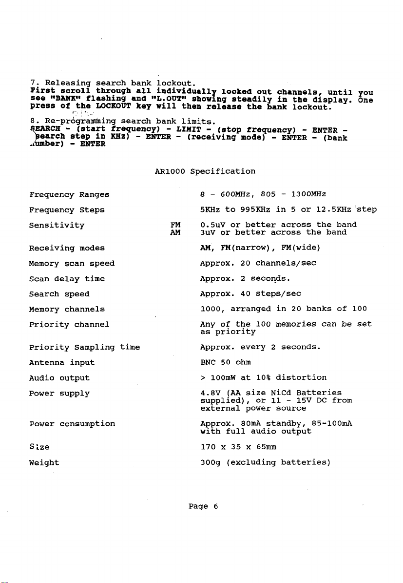
7. Releasing search bank
First scroll through all
B BANK*
see
press
8. ~e-programming search bank limits.
Frequency Ranges
Frequency Steps
Sensitivity
Receiving modes
Memory scan speed
Scan delay time
Search speed
Memory channels
Priority channel
Priority Sampling time
Antenna input
Audio output
Power supply
Power consumption
S ;ze
Weight
flashing and g*I.OUT1l
of the LOCKOUT key
C1
frequency)
KHz) - ENTER
lockout.
individual1
will
ARlOOO Specification
shoring
then release the bank lockout.
-
LIMIT - (stop frequency)
-
(receiving mode)
5KHz to 995KIiz in 5 or 12.5KHz step
FM
AM
0.5uV or better across the band
3uV or better across the band
AM,
Approx. 20 channels/sec
Approx. 2 seconds.
Approx. 40
1000, arranged in 20 banks of 100
Any of the 100 memories can be set
as priority
Approx. every 2 seconds.
BNC 50 ohm
>
4.8V
supplied), or 11
external power source
Approx.
with full audio output
170 x 35 x
300g (excluding batteries)
locked out channels, until you
steadily in the display. One
-
-
ENTER
FM(narrow) , FM(wide)
steps/sec
lOOmW at 10% distortion
(AA
size NiCd Batteries
80mA standby, 85-100mA
65mm
ENTER
-
-
15V DC from
-
(bank
Page
6
 Loading...