

Page 1
INSTALLATION
1. Cautions During Installation
Caution: Dismantling the drive to attempt repairs or for other
reasons is dangerous because the laser may radiate outside
the unit. Do not disassemble the drive.
Caution:
q Install the drive in accordance with the specifications. Be
careful to avoid locations likely to cause vibration or
shock.
q Avoid locations where there is high humidity, much dust,
or poor ventilation.
q Avoid locations in direct sunlight, with severe changes in
humidity, or places where there are extremely high or
low temperatures.
q Don' t use the drive near radio or television receivers. It
may interfere with their reception.
2. Cautions During Use
Caution:
q Don’t suddenly move the drive from a cold place to a
warm one, or suddenly raise the room temperature.
Condensation may occur, causing abnormal operation.
q Make sure to remove the disc before moving the drive.
The disc may be damaged, causing data loss.
q Be careful to prevent foreign objects such as liquids or
metal from entering the drive. Should by chance a
foreign object enter the drive, please consult the dealer
where the drive was purchased.
q Don' t use benzene or thinner to clean dirt from the
drive. Don't allow chemicals such as insecticides to
contact the drive. Use a soft cloth to wipe the drive, or
1
Page 2

moisten a cloth with neutral detergent diluted with water
and use it to clean particularly dirty areas.
q Don' t cutoff the electric power while the drive is
operating.
q When connecting the SCSI cable, observe the following
points.
q If two different devices with the same SCSI ID are
connected to the SCSI bus, the system may fail to
function. Be careful that none of the SCSI Ids are the
same when installing the equipment.
q Keep the total length of the SCSI cable within 6 meters.
q When connecting the SCSI cable to the drive, make sure
the power is OFF.
q Never insert a damaged disc into the drive.
q In wintertime, don' t use a disc soon after bringing in
from outdoors. Use it only after it has reached room
temperature.
3. Cautions Concerning Disc Cleaning
q Remove the disc by pressing the eject button.
q Use compressed air to clear dust from the drive. (Spray the
compressed air for about 5 seconds).
q Check to see if there is dirt on the surface of the disc. Be careful not to
touch the disc with the fingers when doing this.
q After cleaning the disc with compressed air, place it on the disc tray
and load in the drive.
*We suggest using Perfect Duster II (50z.) as compressed air for cleaning.
2
Page 3

4. Other Cautions
Caution:
q When moving the equipment, make sure that the disc
has been removed from the drive.
q When not using the drive for a long period, dust may
adhere to the disc tray. Before using the drive again, use
dry air cleaner to remove the dust from the tray.
q When connecting connectors, make sure that the power
is OFF. If the power is ON, there is a possibility of short
circuit.
5. How to Use the Discs
Caution:
q When using CD-ROM discs, CD-R discs or CD-RW
discs, don' t attach any stickers or labels to the discs.
Using discs with them attached not only causes read
and write errors, but data on the disc may be lost due to
damage to the disc itself.
Load the disc
1 Press the eject button.
2 place the disc on the disc tray.
Caution:
q When using a 120 mm CD, place it in the large round
depression. When using 80 mm CD, place it in the small
round depression. The face with the label on it should be
up. Never place both discs in the tray at the same time.
q Be careful not to touch the recording surface of the disc.
3
Page 4
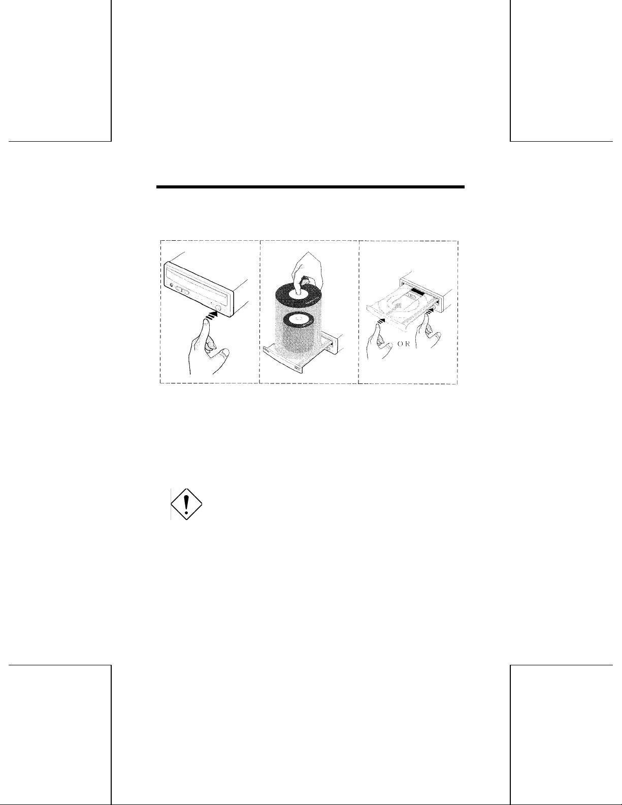
Load the disc by pressing the eject button or by lightly pushing in the disc
tray.
Fig. 1-1 Load the disc
Disc ejection
1. Press the eject button.
2. Slowly take the disc out of the disc tray.
3. Press the eject button or push the disc tray and the tray will be brought
back into the drive.
Caution:
q After ejecting the disc, return the tray inside the unit
quickly. When the tray is in the ejected position, dust
and other debris will enter, possibly causing read errors,
write errors, or drive failure.
4
Page 5

6. Emergency Eject
This drive has a function that allows the CD to be ejected manually if this
becomes necessary in an emergency such as failure of the drive or a
power outage. Follow the following procedures in such a case.
1. Turn the power to OFF.
2. Pinch the disc tray door between the fingers, and slowly pull it straight
out.
5
Page 6

Caution:
q Don' t use this feature except in an emergency. This
feature is a last measure to be used only in an
emergency. Using it excessively will cause
malfunction.
Fig. 1-2 Emergency Eject
6
Page 7

CONSTRUCTION AND INSTALLATION
1. Basic Construction
The Compact Disc Rewriter Drive: The Rewriter consists of following parts.
The Compact Disc Rewriter Drive's configuration, and Connector are
shown below.
Fig. 2-1 Compact Disc Rewriter Drive configuration
7
Page 8

2. Appearance
Dimensions: 146.0 mm x 203.0 mm x 41.5 mm
(Width) (Depth) (Height)
Weight: 1.5 kg or less
3. Connector
The Connectors are located as shown below. The function of each parts
are also described below.
Fig. 2-2 Front
Fig. 2-3 Back
8
Page 9

3.1 Disc Tray
This is the tray for the disc. Place the disc on the ejected disc tray, then
lightly push the tray (or push the eject button) and the CD will be loaded.
Caution: Don' t use force to pull out or push in the disc tray.
This might cause damage to the loading section of the drive.
3.2 Eject Button
This is the button used to eject or bring in the disc tray.
3.3 PowerI Busy Indicator
This indicator light shines green when power is on. When the disc tray or
disc is being accessed, the light shines or flashes orange. Even when a
disc is loaded or a disc is not being accessed, the light shines green. When
an illegal disc is loaded or some hardware trouble occurs, the indicator
blinks.
3.4 Headphone Jack
This jack is for connecting headphones or mini-speakers.
3.5 Volume Control
This is used to adjust the output volume of the headphone jack. It can't be
used to adjust the output volume for the audio output connectors on the
rear panel.
3.6 Power Connector
Used to connect to the host computer' s power supply (DC 5V)
9
Page 10

Caution: Be careful not to reverse the poser connector when
attaching it. A reversed connection may cause damage to
the equipment (not covered by the warranty).
3.7 SCSI connector
Use a 50 pin double-end flat SCSI cable to connect to the SCSI interface.
Caution: Connecting or disconnecting connectors while
power is on may result in a short circuit, causing damage to
the equipment. When connecting or disconnecting
connectors, make sure to turn off the power beforehand.
3.8 Audio Output Connector
Used to connect to the sound card.
3.9 SCSI ID Jumper
Used when selecting the SCSI ID number. Don't use jumpers to change
anything besides the SCSI ID, but keep the drive as initially set (no jumper
pins: ID 0). SCSI ID changes become valid after power is turned off, then
on again.
Caution: Installing jumper pins besides the ones for SCSI ID
settings may be the cuse of damage or abnormal drive
operation.
10
Page 11

Reserved
Reserved
Reserved
Reserved
SCSI ID
Reserved
Fig. 2-4 SCSI ID Jumper
The SCSI ID Jumper will be set to all OFF (Open) as factory setting.
Table 2-1 SCSI ID Jumper setting
Jumper pin Function Factory setting
1 Reserved 0 (OFF/Open)
2 SCSI ID(0) 0 (OFF/Open)
3 SCSI ID(1) 0 (OFF/Open)
4 SCSI ID(2) 0 (OFF/Open)
5 Reserved 0 (OFF/Open)
6 Reserved 0 (OFF/Open)
7 Reserved 0 (OFF/Open)
8 Reserved 0 (OFF/Open)
No 1, 5, 6, 7, 8: Reserved
No 2, 3, 4: SCSI ID
11
Page 12

Table 2-2 SCSI ID
SCSI ID Pin No. 2 Pin No. 3 Pin No. 4 Remark
0 OFF OFF OFF Factory setting
1 ON OFF OFF
2 OFF ON OFF
3 ON ON OFF
4 OFF OFF ON
5 ON OFF ON
6 OFF ON ON
7 ON ON ON *1
Note ON : Jumper Pin is attached
OFF: Jumper Pin is not attached
*1: Don' t use this setting. It is located as the setting for SCSI Adapter Card
usually.
4. Installation
This drive is for setting horizontally. Also, for the angle of the setting
position, make sure it is based on the specification.
By setting the unit out of the specification, the function may operate
incorrectly.
Installation Conditions:
Mounting direction Horizontal
Installation Angle ± 15°or less
12
Page 13

Horizontal
Fig. 2-5 Installation
13
 Loading...