


AX6BC
User's Guide
Printed in Taiwan
PART NO.: 49.87822.081
DOC. NO.: AX6BC-1-E9904E

AX6BC
Mainboard
User's Guide
Document Number |
: AX6BC-1-E9811D |
Model and revision |
: For AX6BC rev 1.xx |
Manual version |
: English, rev D |
Release Date |
: Nov 23, 1998 |
More help for latest information:
Taiwan http://www.aopen.com.tw USA http://www.aopen-usa.com
http://www.aopenusa.om
http://www.aopenamerica.com Europe http://www.aopen.nl

Copyright
Copyright © 1998 by this company. All rights reserved. No part of this publication may be reproduced, transmitted, transcribed, stored in a retrieval system, or translated into any language or computer language, in any form or by any means, electronic, mechanical, magnetic, optical, manual or otherwise, without the prior written permission of this company.
ii

Disclaimer
This company makes no representations or warranties, either expressed or implied, with respect to the contents hereof and specifically disclaims any warranties, merchantability or fitness for any particular purpose. Any software described in this manual is sold or licensed "as is". Should the programs prove defective following their purchase, the buyer (and not this company, its distributor, or its dealer) assumes the entire cost of all necessary servicing, repair, and any incidental or consequential damages resulting from any defect in the software. Further, this company reserves the right to revise this publication and to make changes from time to time in the contents hereof without obligation to notify any person of such revision or changes.
Intel and Pentium are registered trademarks of Intel Corporation.
XT/AT is a registered trademark of International Business Machines Corporation. AMI is a registered trademark of American Megatrends Inc.
AWARD is a registered trademark of Award Software Inc.
Sound Blaster is a registered trademark of Creative Technology Ltd in the United States and certain other countries. Sound Blaster-LINK and SB-LINK are trademarks of Creative Technology Ltd.
Other brand and product names are trademarks and/or registered trademarks of their respective holders.
iii

FCC Class B Radio Frequency
Declaration of Conformity
This equipment has been tested and found to comply with the limits for a Class B Subassembly -CPU Board device, pursuant to Part 15 of FCC Rules. Operation is subject to the following two conditions: 1. This device may not cause harmful interference, and 2. This device must accept any interference received, including interference that may cause undesired operation.
Equipment Classification |
: FCC Class B Subassembly - CPU Board |
Type of Product |
: Intel Pentium II Micro ATX Motherboard |
Chipset(s) |
: Intel 82440BX |
AX6BC
Test To Comply
With FCC Standards
FOR HOME OR OFFICE USE
The limits of FCC Part 15 Class B are designed to provide reasonable protection against harmful interference in a residential installation. This equipment generates, uses, and can radiate radio frequency energy and, if not installed and used in accordance with the instructions, may cause harmful interference to radio communications. However, there is no guarantee that interference will not occur in a particular installation. If this equipment does cause harmful interference to radio or television reception, which can be determined by turning the equipment off and on, the user is encouraged to try to correct the interference by one or more of the following measures:
1.Reorient or relocate the receiving antenna.
2.Increase the separation between the equipment and receiver.
3.Connect the equipment into an outlet on a circuit different from that to which the receiver is connected.
4.Consult the dealer or an experienced radio/television technician for help.
Notice 1:
The changes or modifications not expressly approved by the party responsible for compliance could void the user's authority to operate the equipment.
Notice 2:
Shielded interface cables, if any, must be used in order to comply with emission limits.
iv

Organization
Chapter 1, Overview, covers the introduction and specifications of the system board and special features.
Chapter 2, Hardware Installation, describes hardware jumpers, connectors and memory configuration. There are user friendly drawings to locate jumper and connector.
Chapter 3, AWARD BIOS, explains the system BIOS and tells how to configure the system by setting the BIOS parameters.
Appendix A, Frequently Asked Question, collects most frequently asked question of this product.
Appendix B, Troubleshooting Guide, includes first aid information you need if you meet trouble, the WWW address and worldwide service telephone/fax are also included.
Appendix C, Jumper Table Summary, gives you a tabular summary of the jumper settings discussed in Chapter 2.
v

Conventions
The following conventions are used in this manual:
Text entered by user, default settings, recommended selections
<Enter>, <Tab>,<Ctl>, <Alt>, <Ins>, <Del>, etc
Represent text input by the user, default settings and recommended selections
Represent the actual keys that you have to press on the keyboard.
Note:
Gives bits and pieces of additional information related to the current topic.
Warning:
Alerts you to any damage that might result from doing or not doing specific actions.
Caution:
Suggests precautionary measures to avoid potential hardware or software problems.
Important:
Reminds you to take specific action relevant to the accomplishment of the procedure at hand.
Tip:
Tells how to accomplish a procedure with minimum steps through little shortcuts.
vi

CONTENTS
CHAPTER 1 OVERVIEW |
|
||
1.1 |
SPECIFICATIONS .................................................................. |
4 |
|
1.2 |
OVERCLOCKING .................................................................. |
6 |
|
1.3 |
SUSPEND TO HARD DRIVE................................................. |
9 |
|
1.4 |
ZERO VOLTAGE MODEM WAKE UP............................. |
12 |
|
1.5 |
SYSTEM VOLTAGE MONITORING ................................ |
14 |
|
1.6 |
FAN MONITORING ............................................................. |
14 |
|
1.7 |
CPU THERMAL PROTECTION......................................... |
15 |
|
1.8 |
MULTI-LANGUAGE BIOS.................................................. |
15 |
|
1.9 |
BATTERY-LESS DESIGN.................................................... |
16 |
|
1.10 SOUND BLASTER LINK ................................................... |
16 |
||
CHAPTER 2 HARDWARE INSTALLATION |
|
||
2.1 |
JUMPER AND CONNECTOR LOCATIONS ...................... |
2 |
|
2.2 |
JUMPERS ................................................................................. |
4 |
|
|
2.2.1 |
Selecting the CPU Frequency .................................. |
4 |
|
2.2.2 Setting the CPU Voltage........................................... |
5 |
|
|
2.2.3 |
Clearing the CMOS .................................................. |
5 |
|
2.2.4 |
AGP Ratio................................................................. |
6 |
|
2.2.5 APAR ........................................................................ |
7 |
|
2.3 |
CONNECTORS........................................................................ |
8 |
|
|
2.3.1 |
Power Cable ............................................................. |
8 |
|
2.3.2 |
ATX Soft-Power Switch Connector .......................... |
8 |
|
2.3.3 Fan……………………………………………………….9 |
||
|
2.3.4 |
PS/2 Mouse .............................................................. |
9 |
|
2.3.5 |
Keyboard ................................................................ |
10 |
|
2.3.6 |
Serial Devices (COM1/COM2) ............................... |
10 |
|
2.3.7 |
Printer ..................................................................... |
11 |
|
2.3.8 |
USB Device ............................................................ |
11 |
|
2.3.9 |
Floppy Drive............................................................ |
12 |
|
2.3.10 IDE Hard Disk and CD ROM ................................ |
12 |
|
|
2.3.11 Hard Disk LED ...................................................... |
13 |
|
vii

|
2.3.12 Panel Connector ................................................... |
14 |
|
|
2.3.13 IrDA Connector ..................................................... |
15 |
|
|
2.3.14 Modem Wake-up Connector................................. |
16 |
|
|
2.3.15 LAN Wake-up Connector...................................... |
16 |
|
|
2.3.16 Sound Blaster LINK .............................................. |
17 |
|
2.4 |
|
CONFIGURING THE SYSTEM MEMORY ...................... |
18 |
CHAPTER 3 AWARD BIOS |
|
||
3.1 |
|
ENTERING THE AWARD BIOS SETUP MENU ............... |
2 |
3.2 |
|
STANDARD CMOS SETUP ................................................... |
3 |
3.3 |
|
BIOS FEATURES SETUP....................................................... |
6 |
3.4 |
|
CHIPSET FEATURES SETUP............................................. |
11 |
3.5 |
|
POWER MANAGEMENT SETUP ...................................... |
16 |
3.6 |
|
PNP/PCI CONFIGURATION SETUP................................. |
22 |
3.7 |
|
LOAD SETUP DEFAULTS................................................... |
27 |
3.8 |
|
LOAD TURBO DEFAULTS ................................................. |
27 |
3.9 |
|
INTEGRATED PERIPHERALS .......................................... |
28 |
3.10 |
PASSWORD SETTING....................................................... |
32 |
|
3.11 |
IDE HDD AUTO DETECTION.......................................... |
32 |
|
3.12 |
SAVE & EXIT SETUP......................................................... |
32 |
|
3.13 |
LOAD EEPROM DEFAULT .............................................. |
33 |
|
3.14 |
SAVE EEPROM DEFAULT............................................... |
33 |
|
3.15 |
EXIT WITHOUT SAVING................................................. |
33 |
|
3.16 |
NCR SCSI BIOS AND DRIVERS ...................................... |
33 |
|
3.17 |
BIOS FLASH UTILITY....................................................... |
34 |
|
APPENDIX A FREQUENTLY ASKED QUESTION
APPENDIX B TROUBLESHOOTING
APPENDIX C JUMPER TABLE SUMMARY
viii

Chapter 1
Overview
AX6BC is a new generation Pentium II based system board that utilizes Intel 82440BX AGPset on ATX PCI/ISA platform. This AGPset is designed for Pentium II CPU, and supports new architectures such as high speed AGP graphic port, SDRAM, Ultra DMA/33, Bus master IDE and USB port. It has three Dual in-line Memory Module (DIMM) that allow to install SDRAM memory and expand up to a maximum of 768MB. Since the cache is on the
Pentium II CPU card (connector SLOT1), there is no second level cache onboard Also, AX6BC uses 2M bit Flash ROM BIOS to reserve for future new functions.
Not only above features, AX6BC also implements many special features as following.
Jumper-less Design Pentium II VID signal and SMbus clock generator provide CPU voltage auto-detection and allows user to set CPU frequency through CMOS setup, no jumper or switch is needed. The correct CPU information is saved into EEPROM, with these technologies, the disadvantages of Pentium base jumper-less design are eliminated. There will be no worry of wrong CPU voltage detection and no need to re-open the housing if CMOS battery loss. The only jumper left is to clear CMOS, which is a safety hook if you forget the password.
Battery-less Motherboard AX6BC implements EEPROM and special circuit (patent applied) that allows you to save your current CPU and CMOS Setup configurations without the need of battery. The RTC (real time clock) can also keep running as long as power cord is plugged. If you lose your CMOS data by accident, you can just reload the CMOS configurations from EEPROM and the system will recover as usual.
Suspend To Hard Drive "Immediately" turns on system and goes back to the original screen before power down. You can resume your original work directly from hard disk without go through the Win95 booting process and run your application again. Suspend to Hard Drive saves your current work (system status, memory image) into hard disk. Note that you have to use VESA
1-1
Overview
compatible PCI VGA, Sound Blaster compatible sound card with APM driver, for Suspend to Hard Drive to work properly.
Zero Voltage Modem Wake Up In conjunction with ATX soft power On/Off, it is possible to have system totally power off and wakeup to automatically answer a phone call such as answering machine or to send/receive fax. The most important break through is not only external box modem but also internal modem card can be used to support Modem Wake Up. The AX6BC and MP56 internal modem card implement special circuit (patent applied) to make sure the modem card work properly without any power.
LAN Wake Up This feature is very similar as Modem Wake Up, but it is through local area network. To use LAN Wake Up function, you must have a network card that supports this feature and also need to install a network management software.
RTC Wake Up Timer The Wake Up Timer is more like an alarm, which wakes up and power on your system at a pre-defined time for specific application. It can be set to wake up everyday or on specific date within a month. The date/time accurate is second.
High Efficient Synchronous Switching Regulator Most of the current switching designs are Asynchronous mode, which from the technical point of view, still consumes very high power as well as heat. AX6BC implements high efficient synchronous switching design that the temperature of MOS FET is far less than Schottky diode of asynchronous design.
Over Current Protection Circuit The Over Current Protection was very popular implemented on the Baby AT or ATX 3.3V/5V/12V switching power supply. But unfortunately, the new generation Pentium II CPU uses different voltage that have regulator to transfer 5V to CPU voltage (for example, 2.8V), and make 5V over current protection useless. AX6BC with switching regulator onboard support CPU over current protection, in conjunction with 3.3V/5V/12V power supply provide the full line over current protection.
CPU and Housing Fan Monitoring AX6BC has one more "fan monitoring" function to prevent system overheat. There are two fan connectors, one is for CPU and the other can be an extra housing fan. The system will report and alarm fan malfunction though utility software such as Hardware Monitor utility (Small Icon for Hardware Monitoring).
CPU Thermal Protection AX6BC has a special thermal detection circuit to have warning through application software when the temperature is higher than a predefined value.
System Voltage Monitoring Further more, AX6BC implements a voltage monitoring system, As you turn on your system, this smart design will continue to monitor your system working voltage. If any of the system voltage is over the component's standard. There will be alarm though utility software such as
1-2

Overview
Hardware Monitor utility (Small Icon for Hardware Monitoring) for a warning to user.
Full-range CPU core voltage This motherboard supports the CPU core voltage from 1.3V to 3.5V, that can be applied to various CPU type in future.
FCC DoC certificate AX6BC has passed FCC DoC test. The radiation is very low, you can use any kind of housing.
Powerful utility software supported AOpen Bonus Pack bundled CD contains many useful utilities, such as AOchip, Hardware Monitoring Utility, Suspend to Hard Drive utility, and BIOS flash utility.
Sound Blaster Link The SB-LINK connector can be used to link Creative PCI sound card. If you have a Creative PCI sound card installed, it is necessary to link the card to this connector for compatibility issue under DOS environment.
Multi-language BIOS This breakthrough will help you set BIOS items without the language barrier.
Note: This motherboard is battery-less, that means the RTC (real time clock) can keep running without battery as long as the power cord is plugged. But in case of power failure or the power cord unplugged, you need to reset date and time from "Standard CMOS Setup" section of BIOS Setup. For more information, please see "Chapter 3 BIOS Setup".
1-3

Overview
1.1Specifications
Form Factor |
ATX |
Board Size |
305 mm x 202 mm |
CPU |
Intel Pentium II Processor |
System Memory |
SDRAM or Registered SDRAM, 168-pin DIMM x3, |
|
maximum 768MB. |
Second-level Cache |
On the CPU card (Slot1 connector) |
Chipset |
Intel 82440BX AGPset |
Expansion Slots |
ISA x2, PCI x5 and AGP x1 |
Serial Port |
Two serial ports UART 16C550 compatible, and the |
|
3rd UART for IR function. |
Parallel Port |
One parallel port supports standard parallel port (SPP), |
|
enhanced parallel port (EPP) or extended capabilities |
|
port (ECP). |
Floppy Interface |
Floppy interface supports 3.5 inches drives with |
|
720KB, 1.44MB or 2.88MB format or 5.25 inches |
|
drives with 360KB, 1.2MB format |
IDE Interface |
Dual-channel IDE interface support maximum 4 IDE |
|
hard disks or CDROM, mode 4 , bus master hard disk |
|
drives and Ultra DMA/33 mode hard drives are also |
|
supported. |
USB Interface |
Two USB ports supported by USB bracket, the BIOS |
|
also supports USB driver to simulate legacy keyboard. |
PS/2 Mouse |
Mini-Din PS/2 mouse connector onboard. |
Keyboard |
Mini-Din PS/2 keyboard connector onboard. |
RTC and Battery |
RTC within Intel PIIX4E chipset. Lithium (CR-2032) |
|
battery is an option, no battery is needed if power cord |
|
is plugged. |
BIOS |
AWARD Plug-and-Play, 2M bit Flash ROM BIOS. |
|
Multi-language versions supported. |
1-4

|
Overview |
|
|
Suspend to Hard Drive |
Supported by BIOS, save your work to hard disk and |
|
resume within a very short time. VESA compatible |
|
VGA and Sound Blaster compatible sound card |
|
required. |
Zero Voltage Modem |
Special circuit (patent applied) to support modem ring |
Wake Up |
wake up by external box modem or internal AOpen |
|
F56/MP56 modem card. |
LAN Wake Up |
By using a network card that supports this feature and a |
|
network management software, you can wake up a |
|
system through a local area network. |
RTC Wake Up Timer |
Program the date/time to wake up your system. |
Synchronous Switching |
High efficient synchronous switching regulator. |
Regulator |
|
Over-current Protection |
CPU core voltage over-current protection to prevent |
|
any accident short circuit. |
CPU Thermal |
Warning when CPU temperature is overheat. Option |
Protection |
for OEM to have sensor at CPU heatsink. |
Fan Monitoring |
Two 3-pin fan connectors, warning when CPU or |
|
housing fan is malfunction. |
System Voltage |
Warning when system voltage (5V,12V,3.3V and CPU |
Monitoring |
core) are abnormal |
Sound Blaster Link |
The SB-LINK connector can be used to link Creative |
|
PCI sound card. |
1-5

Overview
1.2Overclocking
As a leading manufacturer in motherboard industry, AOpen always listens to what customers want and develop products to fit different user's requirements. Reliability, compatibility, leading technology and friendly features are our basic goals when designing motherboards. Other than above mentioned design criteria, there are power users who are always seeking to push the limitation of the system performance by overclocking which we call them "Overclocker".
This section is dedicated to Overclockers.
This high performance AX6BC motherboard is designed for maximum 100MHz CPU bus clock. But it comes with clock generator of 153MHz when we design it to accommodate future CPU bus clock. Our lab test results shown that 133.3MHz is achievable when proper setting and quality components were presented, we feel quite comfortable overclocking to 133.3MHz. Not only that, AX6BC has full-range (CPU core voltage) settings and up to 8x CPU ratio, that supports almost all of Pentium II CPUs in the future and provides flexibility for overclockers. For your reference, the following configurations are what we feel comfortable at 112 MHz bus clock. But not guaranty.☺
Warning: The design of this product follows CPU and chipset vendor's design guideline. Any attempts to push beyond product specification are not recommended and you are taking your own risk to damage your system or important data. Before doing overclocking, you must make sure your components are able to tolerate such abnormal setting, especially CPU, DRAMs, hard disks, and AGP VGA cards.
Warning: Note that overclocking may Please make sure that the cooling adequate to dissipate excessive overclocking the CPU.
also cause thermal problem. fan and the heatsink were heat that's generated by
VGA and HDD are key components for overclocking, for your reference, the following list are what have been successful overclocked in our lab. Please note that AOpen can not guaranty they can be successful overclocked again.
1-6

|
|
|
|
|
|
Overview |
||
|
VGA Card |
|
|
|
|
|
|
|
|
|
|
|
|
|
|
|
|
|
VGA model/ Vendor |
Chipset model |
|
|
Driver |
|
||
|
|
|
|
|
|
|
|
|
|
Asus |
|
S3 –Virge/dx(86c375) |
|
|
Asus |
|
|
|
|
|
|
|
|
|
|
|
|
VENUS T-775 |
|
S3 Trio 64V2(86C775) |
|
|
Venus |
|
|
|
|
|
|
|
|
|
|
|
|
VENUS 67TV |
|
Trident 9685 |
|
|
Venus |
|
|
|
|
|
|
|
|
|
|
|
|
GALAXIE |
|
Trident 9685 (PS-68) |
|
|
Venus |
|
|
|
ATI |
|
MACH 64 210888GX00 |
|
|
Win95 default |
|
|
|
|
|
|
|
|
|
|
|
|
MATROX |
|
MY220P/4+ |
|
|
MGA |
|
|
|
|
|
|
|
|
|
|
|
|
MATROX |
|
MGA-MIL/4+ |
|
|
MGA |
|
|
|
|
|
|
|
|
|
|
|
|
MATROX |
|
MIL2P/4+ |
|
|
MGA |
|
|
|
|
|
|
|
|
|
|
|
|
Hard Disk: |
|
|
|
|
|
|
|
|
|
|
|
|
|
|||
|
Vender |
Model |
|
Size |
|
|||
|
Maxtor |
90680D4 |
|
6.8G |
|
|
||
|
|
|
|
|
|
|||
|
Maxtor |
90845D5 |
|
8.4G |
|
|
||
|
|
|
|
|
||||
|
Maxtor |
72004AP |
2.0G |
|
|
|||
|
|
|
|
|
|
|||
|
Maxtor |
82560A4 |
|
2.5G |
|
|
||
|
|
|
|
|
|
|||
|
Seagate |
ST36530A |
|
6.5G |
|
|
||
|
|
|
|
|
|
|||
|
Seagate |
ST31277A |
|
1.2G |
|
|
||
|
|
|
|
|
||||
|
Quantum |
FireballST4320AT |
4.3G |
|
|
|||
|
|
|
|
|
||||
|
Quantum |
T-Rex Bigfoot TX6.0AT |
6.0G |
|
|
|||
|
|
|
|
|
||||
|
Quantum |
T-Rex Bigfoot TX8.0AT |
8.0G |
|
|
|||
|
|
|
|
|
|
|||
|
Quantum |
T-Rex Bigfoot TX12.0AT |
|
12.0G |
|
|
||
|
|
|
|
|
|
|||
|
IBM |
DHEA-34330 |
|
4.3G |
|
|
||
|
|
|
|
|
|
|||
|
IBM |
DTTA-351010 |
|
10.1G |
|
|
||
|
|
|
|
|
||||
|
IBM |
DTTA-350840 |
8.4G |
|
|
|||
|
|
|
|
|
||||
|
IBM |
DTTA-350640 |
6.4G |
|
|
|||
|
|
|
|
|
|
|||
|
IBM |
DAQA-32160 |
|
2.1G |
|
|
||
|
|
|
|
|
|
|
|
|
1-7

Overview
AX6BC Overclocking Settings
The following table lists the overclocking settings in AOpen’s lab for your reference.
CPU Pentium II 350
DRAM ISEC KOREA 752
KM48S8030BT-GH 32MB
HDD IBM DHEA-34330
VGA ATI 3D RAGE PRO AGP 2X
OS Windows 95 OSR2
BIOS Load BIOS Turbo Default
100 MHz * 4 = 400 MHz (OK)
112 MHz * 3.5 = 392 MHz (OK)
133.3MHz * 3 = 400 MHz (OK)
1-8

Overview
1.3Suspend to Hard Drive
Suspend to Hard Drive saves your current work (system status, memory and screen image) into hard disk, and then the system can be totally power off. Next time, when power is on, you can resume your original work directly from hard disk within few second without go through the Win95 booting process and run your application again. If your memory is 16MB, normally, you need to reserve at least 16MB HDD space to save your memory image. Note that you have to use VESA compatible PCI VGA (AOpen PV70/PT70), Sound Blaster compatible sound card and sound driver that supports APM (AOpen AW32/AW35) for Suspend to Hard Drive to work properly. Of course, we recommend to use AOpen products for best compatibility.
To use Suspend to Hard Drive:
1. |
Go into BIOS setup, Power Management Suspend Mode Option, select |
|
"Suspend to Disk". |
2. |
Go into BIOS setup, PNP/PCI Configuration PnP OS Installed, select |
|
"No". This can give BIOS the capability to allocate system resources for |
|
Suspend to Hard Drive. |
3.Boot up your system into DOS command prompt. If you are Win'95 user, Please restart your Windows 95 under "Command Prompt" by pressing "F8" while system shows "Windows 95 Starting ...". Choose "Safe Mode Command Prompt Only" from selection so that system will start in DOS command prompt.
4.Copy AOZVHDD.EXE to the root directory of your C: drive.
5.Option 1: Use /file switch (applied to FAT16 file system):
Please use following command to create a hidden file in the root directory of your hard disk for Suspend to Hard Drive to save the system status and memory image.
C:>AOZVHDD /c /file
Please make sure that you have enough continuous HDD space for creating this hidden file. For example, if you have 32MB of system memory and 4MB of VGA memory, you need at least 36MB (32MB + 4MB) of continuous HDD space. If AOZVHDD failed to allocate the HDD space, you may run "DEFRAG" Utility or "Disk Defragmenter" which come with MSDOS or Win'95 to free HDD space.
1-9

Overview
Option2: Use /partition switch (applied to FAT16/FAT32 file system):
To create a separate partition for Suspend to Hard Drive, please make sure you have reserved a free partition. We suggest you reserve the free partition which space is appropriate for your future memory expansion. For example, if you have 32MB of system memory and 4MB of VGA memory currently, but you plan to upgrade system memory to 64MB in the near future, then you may reserve a 68MB (64MB+4MB) space by using a disk utility (such as fdisk). Next, use following command to create a suspend partition:
C:>AOZVHDD /c /partition
If there is no extra free partition and you don't want your data lost, please do not use this partition method.
6.After creating above partition or hidden file, please reboot your system.
7.Push suspend switch (momentary mode) or use Win95 Suspend icon to force system goes into Suspend to Hard Drive mode and then turn system power off by power switch of your power supply.
8.Next time when you turn on your system, it will resume to your original work automatically.
Warning: Note that Intel Bus Master and Ultra DMA/33 IDE driver are not fully compatible with Suspend to Hard Drive function, installing these drivers may cause the system unstable. Under this situation, please uninstall the drivers.
Warning: This function does not support SCSI hard disks.
1-10

Overview
Tip: The following VGA cards have been tested & recognized as VESA compatible VGA device.
AOpen PV90 (Trident 9680)
AOpen PT60 (S3 Virge/BIOS R1.00-01) AOpen PV60 (S3 Tiro64V+)
AOpen PT70 (S3 Virge/DX) ProLink Trident GD-5440 ProLink Cirrus GD-5430 ProLink Cirrus GD-5446 ATI Mach 64 GX
ATI 3D RAGE II
Diamond Stealth64D (S3 868)
Diamond Stealth64V (S3 968) KuoWei ET-6000
ATI 3D RAGE PRO 2x (AGP) PLOTECH 3D IMAGE 9850 (AGP) CARDEX S3 Virge/GX (AGP)
Tip: The following sound cards have been tested OK for Suspend to Hard Drive.
AOpen AW32
AOpen AW35
AOpen MP32
Creative SB 16 Value PnP
Creative SB AWE32 PnP ESS 1868 PnP
If your sound card can not work after resume from Suspend to Hard Drive, check your sound card vendor see if there is driver to support APM, and install it again.
Note: The USB function has not been tested for Suspend to Hard Drive. If you find any unstable problem, please go into BIOS, Integrated Peripherals USB Legacy Support. Disable the USB Legacy
function.
1-11
Overview
1.4 Zero Voltage Modem Wake Up
The Modem Wake Up discussed here is to wakeup from true power off (identified by fan of power supply is off), This motherboard still supports traditional green PC suspend mode but it is not discussed here.
With the help ATX soft power On/Off, it is possible to have system totally power off (The traditional suspend mode of power management function does not really turn off the system power supply), and wakeup to automatically answer a phone call such as answering machine or to send/receive fax. You may identify the true power off by checking fan of your power supply. Both external box modem and internal modem card can be used to support Modem Wake Up, but if you use external modem, you have to keep the box modem always power-on. AOpen AX6BC and internal modem card implement special circuit (patent applied) and make sure the modem card works properly without any power. We recommend you choose AOpen modem card (MP56) for Modem Wake Up applications.
TEL Line
COM port |
External Box Modem |
External Modem Wake Up
TEL Line
Internal Modem Card Wake Up (such as MP56)
1-12

Overview
For Internal Modem Card (AOpen MP56):
1. Go into BIOS setup , Power Management Modem Wake Up, select Enable.
2.Setup your application, put into Windows 95 StartUp or use Suspend to Hard Drive function.
3.Turn system power off by soft power switch.
4.Connect 4-pin Modem Ring-On cable from MP56 RING connector to AX6BC MODEM-WKUP connector.
5.Connect telephone line to MP56. You are now ready to use Modem RingOn.
For External Box Modem:
1. Go into BIOS setup , Power Management Modem Wake Up, select Enable.
2.Setup your application, put into Windows 95 StartUp or use Suspend to Hard Drive function.
3.Turn system power off by soft power switch.
4.Connect RS232 cable of external box Modem to COM1 or COM2.
5.Connect telephone line to external box Modem. Turn on Modem power (you must keep Modem power always on). You are now ready to use Modem Ring
Tip: External modem wake up signal is detected through COM1 or COM2. Internal modem card wake up signal is detected through cable from connector RING (on modem card) to WKUP (on mainboard).
Tip: You can combine Suspend to Hard Drive, Modem Wake Up and the software Acephone for the best solution of answering machine or to send/receive fax.
Note: If you use external modem, the power of external modem must be kept on to receive signal from telephone line. Internal modem card has no such limitation.
1-13
Overview
1.5System Voltage Monitoring
This motherboard implements a voltage monitoring system. As you turn on your system, this smart design will continue to monitor your system working voltage. If any of the system voltage is over the component's standard. There will be alarm through application software such as Hardware Monitor utility for a warning to user. System voltage monitoring function monitors CPU core voltage. It is automatically implemented by BIOS and Hardware Monitor utility (the file name is like aohw100.exe, where 100 means the version number), no hardware installation is needed.
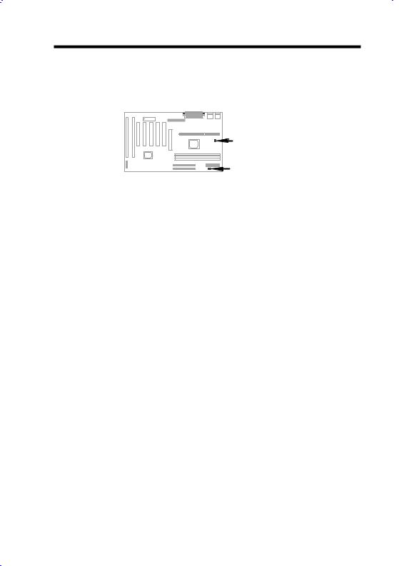
1.6Fan Monitoring
There are two fan connectors, one is for CPU, the other can be a housing fan. The fan monitoring function is implemented by connecting fan to 3-pin fan connector CPUFAN or FAN and installing Hardware Monitor utility.
Note: You need 3-pin fan that supports SENSE signal for fan monitoring function to work properly.
1-14
Overview
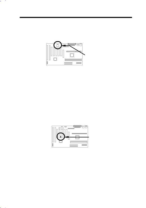
1.7CPU Thermal Protection
Thermistor |
Monitor IC |
This mainboard implements special thermal protection circuits. When temperature is higher than a predefined value, there will be warning through application software such as Hardware Monitor utility to notify user. It is automatically implemented by BIOS and Hardware Monitor utility, no hardware installation is needed.
1.8Multi-language BIOS
For giving AOpen's worldwide users the best support, AOpen software team made every effort to overcome all difficulties and successfully develop a method to provide multi-language BIOS.
You may download and reflash a specified BIOS version from AOpen 's web site (For example, Chinese). After entering BIOS Setup, you can switch to another language by pressing F9. Then pressing F9 again will let you return to English screen.
This breakthrough will help you set BIOS items without the language barrier.
1-15
Overview
1.9Battery-less Design
Battery |
To preserve the earth, AOpen AX6BC implements the world first battery-less motherboard design. There is no need to have battery for RTC (real time clock) and CMOS Setup as long as ATX power cable is plugged. In case of the AC power is shutdown or power cord is removed by accident, the CMOS Setup and system configuration can be restored from EEPROM, only the system clock needed to be re-set to current date/time.
For the convenience of end user, AX6BC still shipped with one Lithium (CR2032) battery. If you prefer to use battery, you can still Insert it into battery socket. The RTC will still keep running even power cord is removed.
1.10 Sound Blaster Link
AX6BC implements a SB-LINK connector to support Creative-compatible PCI sound card. If you have a Creative-compatible PCI sound card installed, it is necessary to link the card to SB-LINK connector for compatibility issue under DOS environment.
1-16

Chapter 2
Hardware Installation
This chapter gives you a step-by-step procedure on how to install your system. Follow each section accordingly.
Caution: Electrostatic discharge (ESD) can damage your processor, disk drives, expansion boards, and other components. Always observe the following precautions before you install a system component.
1.Do not remove a component from its protective packaging until you are ready to install it.
2.Wear a wrist ground strap and attach it to a metal part of the system unit before handling a component. If a wrist strap is not available, maintain contact with the system unit throughout any procedure requiring ESD protection.
2-1

Hardware Installation
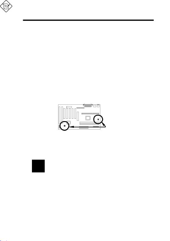
2.1 Jumper and Connector Locations
The following figure shows the locations of the jumpers and connectors on the system board:
|
|
|
|
|
|
IrDA |
|
|
|
|
|
|
Modem-WKUP |
JP14 |
|
LAN Wakeup |
|
|
|
|
|
|
|
|
|
|
|
|
|
|
|
|
|
|
|
BIOS |
|
COM2 |
|
COM1 |
USB |
KB |
|
I |
I |
|
|
|
|
PRINTER |
||||
S |
S |
P |
P |
P |
P |
FDC |
|
|
|
PS/2 |
P |
|
|
|
|
||||||
A |
A |
C |
C |
C |
C |
C |
|
|
|
|
2 |
1 |
I |
I |
I |
I |
I |
CPU SLOT 1 |
|
|
|
|
|
5 |
4 |
3 |
2 |
1 |
|
|
||
|
|
|
|
|
|
A |
|
|
|
|
|
|
|
|
|
|
G |
|
|
|
|
|
|
|
|
|
|
P |
|
|
|
|
|
|
|
|
|
|
|
|
|
|
CPU FAN |
|
|
|
|
SB-Link |
|
|
|
|
|
|
|
|
|
|
|
|
|
|
|
DIMM1 |
|
|
|
|
|
|
|
|
|
|
DIMM2 |
|
|
|
|
|
|
|
|
|
|
DIMM3 |
|
HDD |
|
|
|
|
JP23 |
|
|
|
|
|
LED |
|
|
|
|
|
|
|
|
||
JP25 |
|
FAN |
|
|
|
|
IDE2 |
|
|
|
|
|
SPWR |
|
|
|
|
IDE1 |
|
PWR2 |
|
PANEL |
|
|
|
|
|
|
|
|
||
|
|
|
|
|
|
|
|
|
||
|
|
|
|
|
|
|
|
|
|
|
2-2

Hardware Installation
Jumpers:
JP14: |
Clear CMOS |
JP23: |
AGP Turbo |
JP25: |
APAR |
Connectors:
PS2: |
PS/2 mouse connector |
KB: |
PS/2 keyboard connector |
COM1: |
COM1 connector |
COM2: |
COM2 connector |
PRINTER: |
Printer connector |
PWR2: |
ATX power connector |
USB: |
USB connector |
FDC: |
Floppy drive connector |
IDE1: |
IDE1 primary channel |
IDE2: |
IDE2 secondary channel |
CPUFAN: |
CPU Fan connector |
FAN: |
Housing Fan Connector |
IrDA: |
IrDA (Infrared) connector |
HDD LED: |
HDD LED connector |
PANEL: |
Front panel (Multifunction) connector |
SPWR: |
ATX Soft-Power Switch Connector |
MODEM-WKUP: Modem Wake Up Connector |
|
LAN-WKUP: |
Lan Wake Up Connector |
SB-LINK: |
Creative PCI sound card connector |
2-3

Hardware Installation
2.2 Jumpers
With the help of Pentium II VID signal and SMbus, this motherboard is jumperless design.
2.2.1 Selecting the CPU Frequency
Pentium II VID signal and SMbus clock generator provide CPU voltage autodetection and allow user to set CPU frequency through CMOS setup, no jumper or switch is needed. The correct CPU information is saved into EEPROM, with these technologies, the disadvantages of Pentium base jumper-less design are eliminated. There will be no worry of wrong CPU voltage detection and no need to re-open the housing if CMOS battery loss.
The CPU frequency selection is set by going into:
BOIS Setup Chipset Features Setup CPU Clock Frequency
(The possible setting is 66.8, 68.5, 75, 83.3, 100, 103, 112, 117, 124, 129, 133.3, 138, 143, 148 and 153 MHz)
BOIS Setup Chipset Features Setup CPU Clock Ratio
(The possible setting is 1.5x, 2x, 2.5x, 3x, 3.5x, 4x, 4.5x, 5x, 5.5x, 6x, 6.5x, 7x, 7.5x, and 8x)
Core frequency = Ratio * External bus clock
INTEL Pentium II |
CPU Core Frequency |
Ratio |
External Bus Clock |
Pentium II - 233 |
233MHz = |
3.5x |
66MHz |
Pentium II - 266 |
266MHz = |
4x |
66MHz |
Pentium II - 300 |
300MHz = |
4.5x |
66MHz |
Pentium II - 333 |
333MHz = |
5x |
66MHz |
Pentium II - 350 |
350MHz= |
3.5x |
100MHz |
Pentium II - 400 |
400MHz= |
4x |
100MHz |
Pentium II - 450 |
450MHz= |
4.5x |
100MHz |
Warning: INTEL 440BX chipset supports maximum 100MHz external CPU bus clock, the higher clock settings are for internal test only. These settings exceed the specification of BX chipset, which may cause serious system damage.
2-4
Hardware Installation
2.2.2 Setting the CPU Voltage
This motherboard supports Pentium II VID function, the CPU core voltage is automatically detected, the range is from 1.3V to 3.5V.
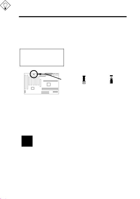
2.2.3 Clearing the CMOS
JP14 Clear CMOS
1-2 Normal operation (default)
2-3 Clear CMOS
You need to clear the CMOS if you forget your system password. To clear the CMOS, follow the procedures listed below:
JP14 |
JP14 |
1 |
1 |
2 |
2 |
3 |
3 |
Normal Operation |
Clear CMOS |
(default) |
|
The procedure to clear CMOS:
1.Turn off the system and unplug the AC power.
2.Remove ATX power cable from connector PWR2.
3.Locate JP14 and short pins 2-3 for a few seconds.
4.Return JP14 to its normal setting by shorting pins 1-2.
5.Connect ATX power cable back to connector PWR2.
6.Turn on the system power.
7.Press  during bootup to enter the BIOS Setup Utility and specify a new password, if needed.
Tip: If your system hangs or fails to boot because of overclocking, please clear CMOS and the system will go back to default setting (233MHz).
Tip: If your system hangs or fails to boot because of overclocking, simply use <Home> key to restore to the default setting (233MHz). By this smart design, it would be more convenient to clear CPU frequency setting. For using this function, you just need to press <Home> key first and then press Power button at the same time. Note that do not release <Home> key until POST sreen appearing.
2-5
 Loading...