

Page 1

High-speed
CD-ROM Drive
User’s Guide
CLASS 1 LASER PRODUCT
CAUTION: INVISIBLE LASER RADIA-
TION WHEN OPEN. AVOID EXPOSURE
TO BEAM.
APPAREIL A LASER CLASSE 1 PRODUIT LASER
ATTENTION: RADIATION DU FAISCEAU LASER INVISIBLE EN CAS
D’OUVERTURE. EVITTER TOUTE EXPOSITION AUX RAYONS.
LUOKAN 1 LASERLAITE LASER
KLASSE 1
VORSICHT: UNSICHTBARE LASERSTRAHLUNG, WENN ABDECKUNG
GEÖFFNET NICHT DEM STRAHLL
AUSSETZEN.
PRODUCTO LÁSER DE LA CLASE 1
ADVERTENCIA: RADIACIÓN LASER
INVISIBLE AL SER ABIERTO. EVITE
EXPONERSE A LOS RAYOS.
ADVARSEL: LASERSTRÅLING VED
ÅBNING SE IKKE IND I STRÅLEN.
VARO! AVATTAESSA OLET ALTTINA
LASERSÄTEILYLLE
VARNING: LASERSTRÅLNING NÄR
DENNA DEL ÄR ÖPPNAD
ÄLÄ TUIJOTA SÄTEESEEN
STIRRA EJ IN I STRÅLEN
VARNING: LASERSTRÅLNING NÄR
DENNA DEL ÄR ÖPPNAD
STIRRA EJ IN I STRÅLEN
ADVARSEL: LASERSTRÅLING NÅR
DEKSEL ÅPNES
STIRR IKKE INN I STRÅLEN
Page 2

Copyright
Copyright 1997 by this company. All rights reserved. No part of this publication may
be reproduced, transmitted, transcribed, stored in a retrieval system, or translated into
any language or computer language, in any form or by any means, electronic,
mechanical, magnetic, optical, chemical, manual or otherwise, without the prior written
permission of this company.
Disclaimer
This company makes no representations or warranties, either expressed or implied, with
respect to the contents hereof and specifically disclaims any warranties, merchantability
or fitness for any particular purpose. Any software described in this manual is sold or
licensed "as is". Should the programs prove defective following their purchase, the buyer
(and not this company, its distributor, or its dealer) assumes the entire cost of all
necessary servicing, repair, and any incidental or consequential damages resulting from
any defect in the software. Further, this company reserves the right to revise this
publication and to make changes from time to time in the contents hereof without
obligation to notify any person of such revision or changes.
MTRP is a trademark of AOpen Incorporated.
MS-DOS is a registered trademark of Microsoft Corporation.
Other brand and product names are trademarks and/or registered trademarks of their
respective holders.
Page 3
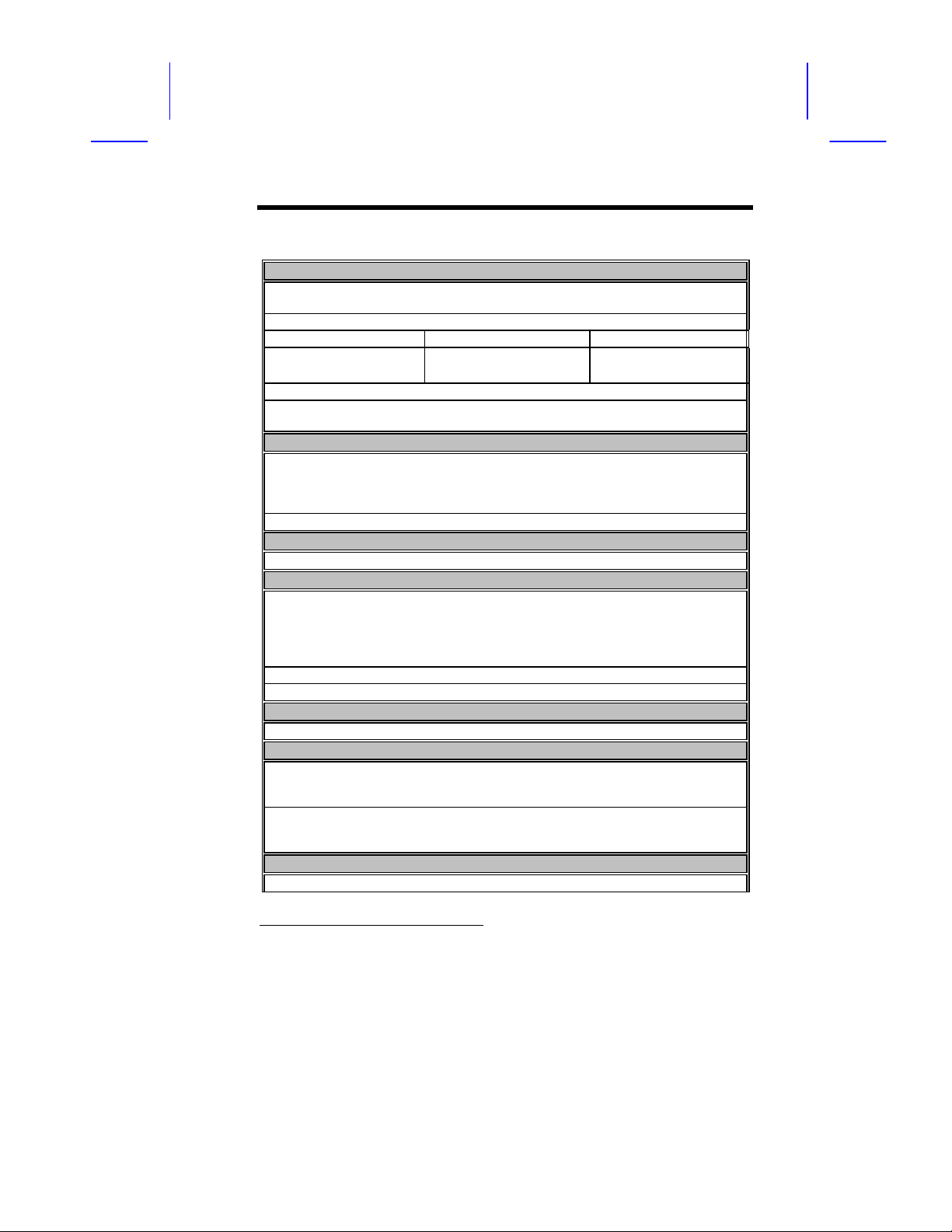
Table of Contents
Specifications
DRIVE PERFORMANCE
Disc Data Capacity: Mode 1
Mode 2
Maximum Playing Time 74 minutes and 42 seconds
Data Transfer Rate (KB/s) Mode 1 Mode 2
Normal speed
Data Buffer Size 128 KB
Drive Reliability (MTBF) 50,000 POH (25% duty cycle at room
COMPACT DISC
Disc Type (data format) CD-Audio, CD-ROM (modes 1 and 2),
Disc Size 80-mm and 120-mm discs
INTERFACE
Drive Interface Type E-IDE (conforms to SFF8020 v1.2)
AUDIO
Analog Audio Output Ports
Digital Audio Output Port
Audio Sampling Frequency 44.1 KHz
Audio Quantization 16 bits
POWER REQUIREMENTS
Voltage +5V, +12V
PHYSICAL CHARACTERISTICS
Front Panel Load/Eject button, Play/Skip button,
Rear Panel Power-supply connector, IDE interface connector,
PHYSICAL CHARACTERISTICS
Mount Both vertical and horizontal
MTRP
1
656 MB
748 MB
150
150 * X
temperature)
CD-ROM/XA (mode 2, form 1 and form 2),
CD-EXTRA, CD-I, Photo-CD (single and multiple
sessions), CD-WO, I-Trax CD, CD-RW
Headphone jack on front panel
Line-out connector on the rear end of the drive
(two stereo channels for each output port)
Two-pin line out connector on the rear end of the
drive
Power-on/Busy LED indicator, 3.5-mm stereo
headphone jack, rotary volume control knob
master/slave jumper, analog audio output
connector, digital audio output connector
171
171 * X
1
MTRP (Maximum Transfer Rate Performance) = normal speed * CD-ROM drive
speed. (Tolerance 10%) Example: 32X CD-ROM MTRP = 150*32 = 4800 KB/sec.
iii
Page 4

Dimensions 149 mm x 42 mm x 196.5 mm (5.9”x1.7”x7.7”)
Weight
≤ 1.0 kg (2.2 lbs)
ENVIRONMENTAL REQUIREMENTS
Temperature: Operating
Non-operating
Humidity: Operating
Non-operating
+5ºC ~ +45ºC
-20ºC ~ +55ºC
20% ~ 80% RH
20% ~ 80% RH
LASER COMPONENT RADIATION DATA
Wavelength
285 ± 25nm
Emission light output power Less than 0.3 mW
Pulse times The time base is using 100s by requirement of IEC
825-1
-1993
clause 9.3 (e)
Page 5

Table of Contents
1 Installing the CD-ROM Drive
Before you begin, turn off the system power. Follow the steps below to install
the CD-ROM drive:
1. Remove the cover from your system. Refer to your system user’s manual.
2. Adjust the Master/Slave jumpers on the back of the CD-ROM drive as
necessary. (The factory default of the slave mode normally should not be
changed. Please refer to Section 4 for more information)
3. Insert the CD-ROM drive unit into a free 5.25-inch drive bay. Secure the
CD-ROM drive to the drive bay rails with the mounting screws (included in
the CD-ROM package). Refer to your system manual for instructions on
how to install a drive.
4. Plug a free power connector inside your PC into the Power socket on the
back of the CD-ROM drive.
5. Plug a free IDE connector inside your PC into the drive’s IDE interface
socket.
Audio Cable
Red Strip
IDE Cable
Red Strip
NOTE: The red edge of the IDE cable corresponds to pin 1 of the IDE
interface on the CD-ROM drive.
If you have a sound card, you can also connect a 4-pin analog audio
cable to the analog audio-out connector of your CD-ROM drive and the
audio-in connector of the sound card.
If you have a digital audio device, you can also connect a 2-pin digital
audio cable to the digital audio-out connector of your CD-ROM drive and
the audio-in connector of your digital audio device.
6. Replace the cover and turn on the power.
Power Cable
v
Page 6

2 Installing the CD-ROM Drivers
The CD-ROM package comes with an installation utility. This utility installs the
CD-ROM drivers needed by your CD-ROM drive to interact with your PC. The
driver installation diskette includes the following files:
• AOATAPI.SYS
• INSTALL.EXE
• README.TXT
• READMEJ.TXT
NOTE: The INSTALL.EXE file automatically detects the system language
environment.
For DOS and Windows 3.1
To install the driver in DOS or Windows 3.1:
1. Insert the installation diskette in your 3.5-inch diskette drive and make it
the active drive.
2. At the DOS prompt, type:
INSTALL
3. Follow the screen instructions to complete the installation.
The installation program creates a directory (C:\CDROM) containing the
CD-ROM drivers. It also updates your AUTOEXEC.BAT and
CONFIG.SYS files as follows:
CONFIG.SYS
DEVICE=C:\CDROM\AOATAPI.SYS /D:IDECD000
LASTDRIVE=N
AUTOEXEC.BAT
C:\DOS\MSCDEX.EXE /D:IDECD000
Changing the Settings After Installation
To reconfigure the settings of the CD-ROM driver, use a text editor (such as
EDIT.COM) to modify the DEVICE= and LASTDRIVE= command lines in the
CONFIG.SYS and AUTOEXEC.BAT files. Then restart your computer.
Page 7

Table of Contents
Changing the CONFIG.SYS File and Enabling the DMA Function
Add the following line to your CONFIG.SYS:
DEVICE = <PATH>\AOATAPI.SYS /D:<DEVICE_NAME> [/zzzz]
[/P:xxx,yy]
The <DEVICE_NAME> is the name of the MSCDEX file that will be used to find
the device driver. The maximum length of the <DEVICE_NAME> string is eight
characters.
The option [/zzzz] in character form specifies the DMA function, the Ultra-DMA
33 function or Bus Master DMA function. Please refer to the README.TXT file
for more details.
For example:
DEVICE=C:\CDROM\AOATAPI.SYS /D:IDECD000 /DMA /P:1F0,14
If your system board supports the Bus Master DMA function, the option /DMA
enables the Bus Master DMA function.
The option /P: specifies the I/O port address and IRQ level. The number xxx
in hexadecimal form specifies the I/O port address (such as 1F0, 170, 1E8, or
168), and yy specifies the IRQ level (such as 14, 15, 11, or 10 in decimal).
NOTE: If you are not familiar with I/O Port or IRQ level settings, do
not implement/P: option.
After changing the CONFIG.SYS, reboot the system.
Refer to the README.TXT file for the latest driver installation
updates.
For Windows 95 and Windows NT Environment
Windows 95 and Windows NT will automatically detect the new CD-ROM drive
and load the appropriate device driver. However, there are times when
Windows can not detect the CD-ROM drive. You will have to load the drivers
manually.
To install the drivers manually:
1. Click the Control Panel Icon in My Computer and then click Add
New Hardware. The Add New Hardware window appears.
2. The program will automatically search for your new CD-ROM Drive and
load the appropriate driver.
vii
Page 8

For OS/2 Warp
Under OS/2 Warp, select the non-listed CD-ROM option. This option supports
the standard ATAPI CD-ROM drives. After selecting this option, OS/2 will autodetect the CD-ROM drive.
3 Using the CD-ROM Drive
In most cases, software applications that utilize CD-ROM drives control the CDROM drive operations directly. However, you can control the drive manually
using the front-panel controls.
1. Headphone Jack
The 3.5-mm stereo headphone jack allows you to listen to audio CDs via
stereo headphones.
2. Volume Control
The volume control is a rotary knob that allows you to control the sound
level from the headphone jack.
3. Power-on/Busy LED
The Power-on/Busy LED indicator lights up when the CD-ROM drive is
being accessed. The LED blinks during a seek operation.
4. Play/Skip Button
The Play/Skip button allows you to play and skip tracks on an audio CD.
5. Load/Eject Button
The Load/Eject button opens the motorized CD tray for loading and
removing CDs. When an audio CD is being played, pressing this button
stops the playing of the CD.
6. Emergency-eject Hole
The emergency-eject hole allows the user to open the CD tray when the
system has no power. (This function is only available with 32x speed CDROM and up)
7. Disc Tray
The disc tray opens and closes for the loading and removal of CDs.
Page 9

Table of Contents
4 Emergency-eject Option
The Emergency-eject option allows the user to manually open the CD tray
during a power malfunction.
Follow these steps to manually open the disc tray:
1. Locate the tiny hole at the bottom of the disc tray. Gently poke the hole
three times with a sharp needle or a clip.
2. When the disc tray opens, pull out the tray and remove the disc from the
CD-ROM drive.
If your CD-ROM does not have an emergency-eject hole follow these steps:
1. Locate the bottom edge of the disc tray. Gently pry the disk tray open
with a screwdriver.
2. When the disc tray opens, simply remove the disc from the CD-ROM
drive.
NOTE: Do not do this unless absolutely necessary. This procedure
may damage the CD tray.
ix
Page 10

5 Jumper Settings
This appendix explains the jumper settings on the drive and lists the pin
configurations of each connector on the rear panel.
There is one jumper at the rear of the CD-ROM drive. This jumper determines
how your CD-ROM drive functions. The figure and table below show the four
possible jumper settings and their functions.
Jumper Setting Function
C Use CSEL
M Master
S Slave
None Slave
The drive comes preset with the jumper at the S pin. This means that the drive
is set as a slave. In this case, your hard disk drive would be the master drive.
To change the jumper setting, remove the jumper cap and insert the pin for the
desired function.
6 FAQ
If you have any questions about the CD-ROM please refer to this website:
http://www.aopen.com.tw
This website provide answers to frequently asked questions about our product.
 Loading...