

Page 1

AAXX66C
L
L
OOnnlliinne
e
MMaannuuaal
A
C--
AX6C-L
DOC. NO. : AX6CL-OL-E0010B
1
l
Open
Page 2

O
X66CC--LL
AAX
Onnlliinnee MMaannuuaall
BBeeffoorree YYoouu SSttaarrtt
This Online Manual is in PDF forma
viewing, it is included in B onus CD disc
Although this Online Manual is optimized for sc reen viewing, it is still capable for hardcopy printing,
you can print it by A4 paper size and s et 2 pages per A4 sheet on your printer. To do so, choose
File > Page Setup
Thanks for the help of saving our eart h.
and follow the instruction of your pri nter driver.
t, we recommend using A dobe A crobat Reader 4.0 for online
or you can get free download from Adobe web site.
2
A
Open
Page 3

O
X66CC--LL
AAX
Onnlliinnee MMaannuuaall
QQuuiicckk IInnssttaallllaattiioonn PPrroocceedduurree
This page gives you a quick procedure on how to ins tall your system. Follow each s tep accordingly.
Installing CPU and Fan
1111
Installing System Memory (RIMM)
2
2
2 2
Connecting Front Panel Cable
3
3
3 3
Connecting IDE and Floppy Cable
4
4
4 4
Connecting ATX Power Cable
5
5
5 5
Connecting Back Panel Cable
6
6
6 6
Power-on and Load BIOS Setup Default
7
7
7 7
Setting CPU Frequency
8
8
8 8
Reboot
9
9
9 9
Installing Operating Syst em (such as Windows 98)
10
10
10 10
Installing Driver and Utility
11
11
11 11
3
A
Open
Page 4
O
p
r
p
R
X66CC--LL
AAX
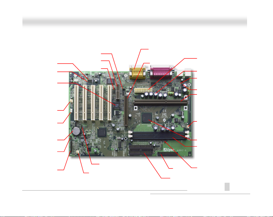
JP29 Onboard Sound
CD Audio
Modem Audio
4Mb Flash BIOS
Virus Protection
Wake on Time
Multi-Languare BIOS
Wakeu
Housing Fan
WOL
Wakeup on LAN
Battery-less
WOM
on Modem
Panel Connector
AM
IrDA
Housing Fan
Motherboard Map
PC99 Back Panel
4X AGP
4
Onnlliinnee MMaannuuaall
ATX Power Connector
AC Power Auto Recovery
Low ESR capacitor
Resettable Fuse
JP28 KB/MS Wakeu
Jumper-less Design
Over-current Protection
Thermal Protection
CPU Fan Connector
System Voltage & Fan
Monitoring
Intel 820 Chipset
PC800 RIMM
Full-range RDRAM Speed
FDC
ATA/66 IDE
Suspend to HDD
RAM Power LED
A
Open
Page 5
O
X66CC--LL
AAX
Onnlliinnee MMaannuuaall
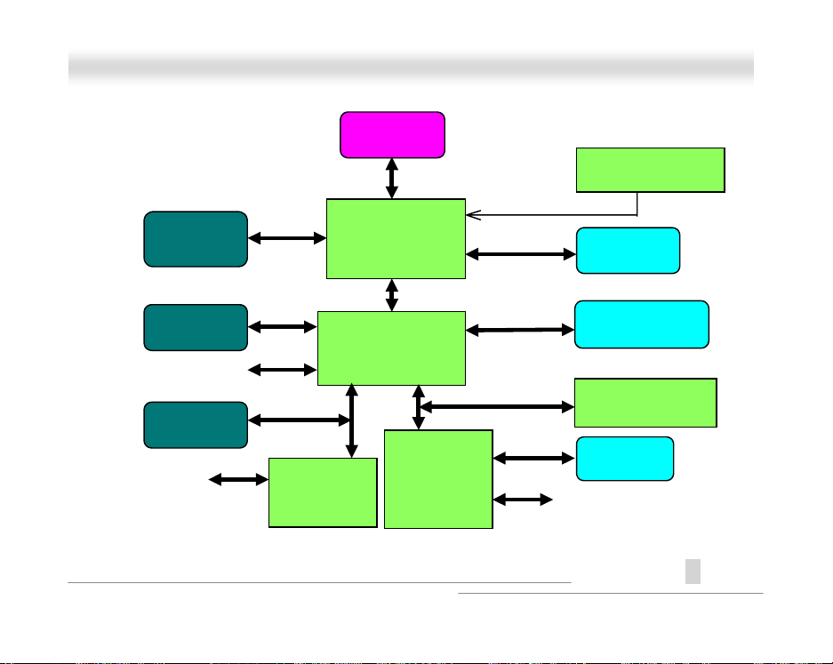
BBlloocckk DDiiaaggrraamm
AGP Card
PCI Card
USB
AMR Card
MIC, Line-in and
Speaker
4X AGP
PCI Bus
AC97 Link
Bus
CODEC
Memory Control
Hub (MCH)
I/O Control Hub
Audio
CPU
100/133MHz FSB
Hub Link
(ICH)
Low Pin
Count
Super I/O
5
Clock Generator
Rambus
ATA/66
IDE Bus
LPC I/F
RIMM
HDD/CDROM
4Mb BIOS ROM
Floppy
Serial port, Printer and
PS/2 KB/Mouse
A
Open
Page 6

O
k
e
u
m
X66CC--LL
AAX
Onnlliinnee MMaannuuaall
HHaarrddwwaarree
This chapter describes j umpers, connectors and hardware devices of this motherboard.
Note: Electrostatic discharge (ESD) can damage your processor, dis
drives, expansion boards, and other components. Always observe th
following precautions before you install a system component.
1.Do not remove a component from its protective packaging until yo
are ready to install it.
2.Wear a wrist ground strap and attach it to a metal part of the syste
unit before handling a component. If a wrist strap is not available,
maintain contact with the system unit throughout any procedure
requiring ESD protection.
6
A
Open
Page 7
O
X66CC--LL
AAX
Onnlliinnee MMaannuuaall
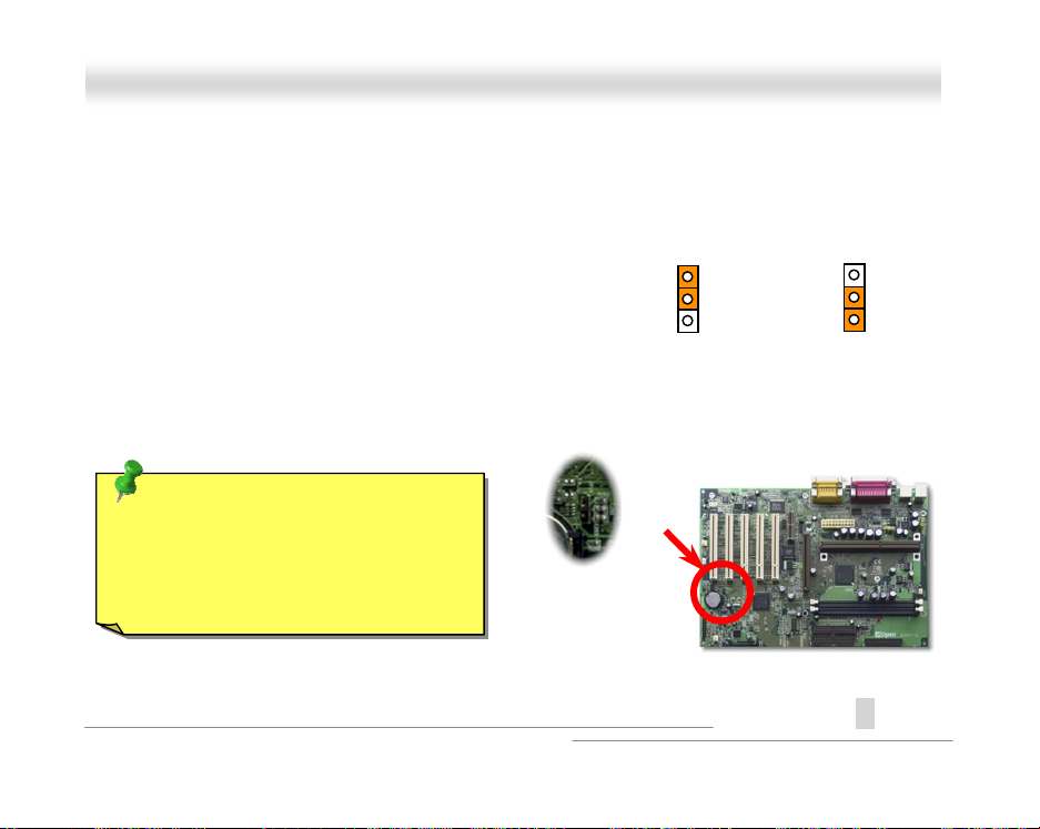
JJPP1144 CClleeaarr CCMMOOSS
You can clear CMOS to restore system default sett i ng. To clear the CMOS, follow the procedure
below.
1. Turn off the system and unplug the AC power.
2. Remove ATX power cable from ATX power connector.
3. Locate JP14 and short pins 2-3 for a few seconds.
4. Return JP14 to its normal setting by shorting pi ns 1-2.
5. Connect ATX power cable back to ATX power connector.
Tip: When should I Clear CMOS?
1. Boot fail because of overclocking…
2. Forget password…
3. Troubleshooting…
1
2
3
Normal Operation
(default)
Clear CMOS
A
7
1
2
3
Open
Page 8
O
X66CC--LL
AAX
Onnlliinnee MMaannuuaall
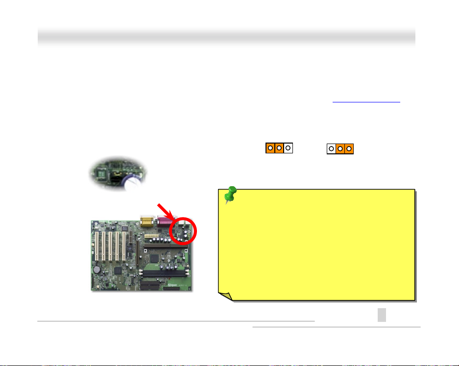
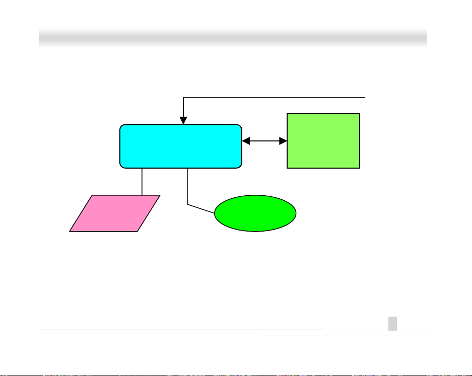
JJPP2288 KKeeyybbooaarrdd//MMoouussee WWaakkeeuupp
This jumper is used to enable or disable Keyboard/Mouse Wake Up function. If you select Enable,
you can decide the wake up mode from BIOS Setup > Integrated Peripherals > Power On Function
To implement this function, the power supply 5V standby current must be greater than 800mA. Note
that only PS/2 mous e supports Wake on Mouse funct i on.
8
1 2 3
Disable
Tip: You have to wait for system to
successfully boot from operation system
(such as Windows or DOS) before the
Wake-On-Keyboard/Mouse can take effect.
This is because the information of how to
support this function must be stored into
Super I/O Controller and then you can use it
for next power on.
1 2 3
Enable
A
Open
.
Page 9
O
X66CC--LL
AAX
Keyboard
Super I/O Controller
PS2 Mouse
9
ATX standby power
Onnlliinnee MMaannuuaall
BIOS
A
Open
Page 10
O
X66CC--LL
AAX
Onnlliinnee MMaannuuaall
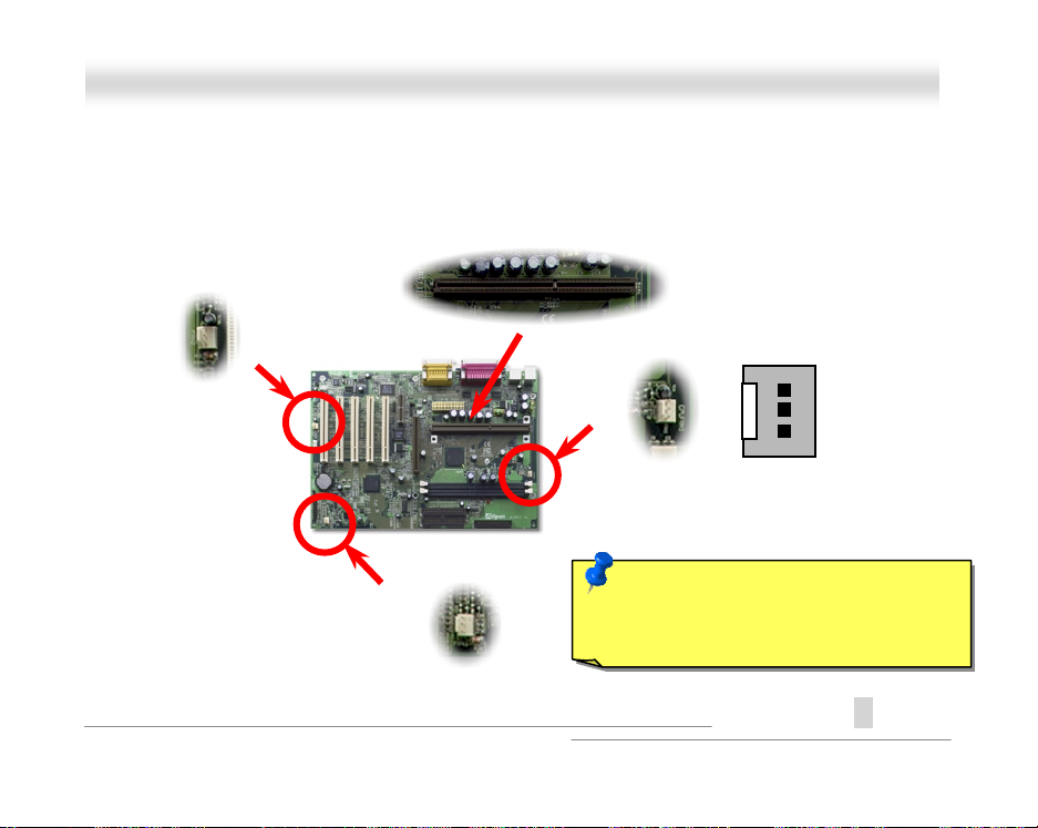
CCPPUU SSlloott aanndd FFaann CCoonnnneeccttoorr
Plug CPU to slot1 connec tor. Be careful of CPU orientation. Plug in the fan cable to the 3-pin
or
CPUFAN
connector.
FAN
GND
+12V
SENSE
Note: Some CPU fans do not have
sense pin, so that cannot support fan
monitoring.
A
10
Open
Page 11
O
X66CC--LL
AAX
Onnlliinnee MMaannuuaall
CCPPUU JJuummppeerr--lleessss DDeessiiggnn
CPU VID signal and SMbus cl ock generator provide CPU voltage auto-detec tion and allows the
user to set the CPU frequenc y through the BIOS setup
The correct CPU information is saved into the EEPROM
disadvantages of the Pentium based jumper-less designs are eliminated. There will be no worry of
wrong CPU voltage detection and no need to re-open the housing in case of CMOS battery loss.
Pentium II/III &
Celeron CPU
, therefore no jumpers or switches are used.
. With these technologies, the
Clock
Generator
CPU Freq. Ratio
BIOS
Controlled
Circuit
CPU VID Signal
(Automatically generates CPU voltage)
Power Regulator
CPU voltage
11
A
Open
Page 12

O
X66CC--LL
AAX
Onnlliinnee MMaannuuaall
Setting CPU Core Voltage
This motherboard supports CPU V I D function. The CPU core voltage will be automatic ally det ec ted
and the range is from 1.3V t o 3.5V..
A
12
Open
Page 13
O
X66CC--LL
AAX
Onnlliinnee MMaannuuaall
Setting CPU Frequency
This motherboard is CPU jumper-less design, you can set CPU frequency through the BIOS setup,
no jumpers or switches are needed.
BIOS Setup > Frequency Control > CPU Speed Setting
CPU Ratio
CPU FSB
3.5x, 4x, 4.5x, 5x, 5.5x, 6x, 6.5x, 7x, 7.5x, and 8x
100.2, 105, 114, 120, 124, 128.5, 133.3, 133.9, 138, 143, 148, 150, 152.5,
155, and 160 MHz.
Warning: INTEL 820 chipset supports maximum
133MHz FSB and 66MHz AGP clock, higher clock
setting may cause serious system damage.
Tip: If your system hangs or fails to boot because of
overclocking, simply use JP14 to clear CMOS and restore to
the default setting (350MHz when FSB=100MHz; 267MHz
when FSB=133.3MHz ).
A
13
Open
Page 14
O
X66CC--LL
AAX
Core Frequency = CPU FSB Clock * CPU Ratio
CPU CPU Core Frequency FSB Clock Ratio
Celeron 300A 300MHz = 66MHz 4.5x
Celeron 366 366MHz= 66MHz 5.5x
Celeron 366 366MHz= 66MHz 5.5x
Celeron 400 400MHz= 66MHz 6x
Pentium II 233 233MHz = 66MHz 3.5x
Pentium II 333 333MHz = 66MHz 5x
Pentium II 350 350MHz= 100MHz 3.5x
Pentium II 400 400MHz = 100MHz 4x
Penti um III 450 450MHz= 100MHz 4.5x
Penti um III 500 500MHz = 100MHz 5x
Penti um III 533EB 533MHz = 133MHz 4x
Penti um III 550E 550MHz = 100MHz 5.5x
14
Onnlliinnee MMaannuuaall
A
Open
Page 15

O
X66CC--LL
AAX
Penti um III 600E 600MHz = 100MHz 6x
Penti um III 600EB 600MHz = 133MHz 4.5x
Penti um III 650E 650MHz = 100MHz 6.5x
Penti um III 667EB 667MHz = 133MHz 5x
Penti um III 700E 700MHz = 100MHz 7x
Penti um III 733EB 733MHz = 133MHz 5.5x
15
Onnlliinnee MMaannuuaall
A
Open
Page 16
O
X66CC--LL
AAX
Onnlliinnee MMaannuuaall
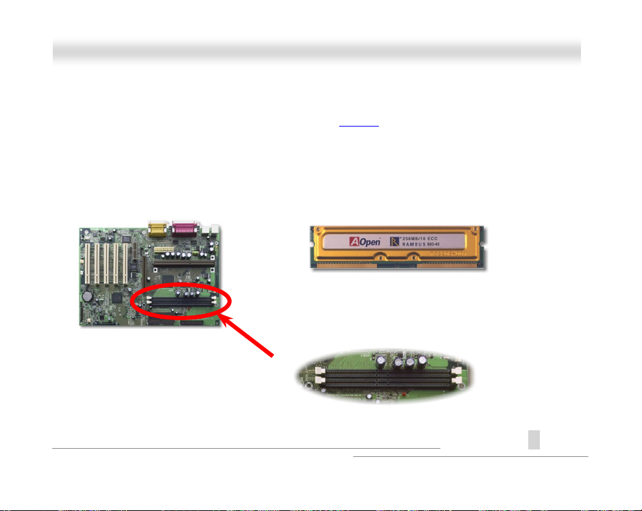
RRIIMMMM SSoocckkeett
Intel 820 chipset supports 16/18 bit Direct RAMBUS (RDRAM) configurations and supports a
maximum of 32 devices on a RDRAM channel. A channel can be populated with mix of 64Mbit,
128Mbit, and 256Mbit RDRAM devices. Hence, the maxim um system memory will be various
depends on the number of RDRAM devices and t he RDRAM device technology. This motherboard
has two 184-pin RIMM sockets that al l ow you to install system memory up to
.
1GB
Example Picture of RIMM
Pin 1
RIMM1
RIMM2
A
Open
16
Page 17
O
X66CC--LL
AAX
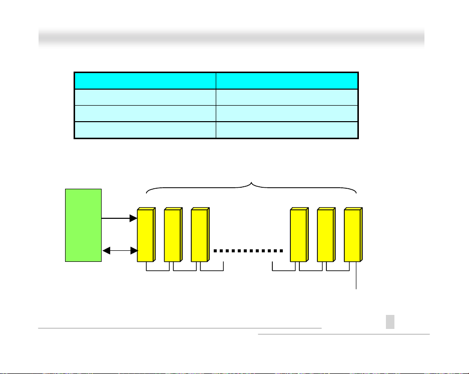
MCH
Onnlliinnee MMaannuuaall
RDRAM Technology Maximum Memory on Channel
64 or 72Mbit with parity 256MB
128 or 144Mbit with parity 512MB
256 or 288Mbit with parity 1GB
RDRAM Devices
#1
#2
Control
Data 16/18 bit
17
#32
Terminator
A
Open
Page 18
O
X66CC--LL
AAX
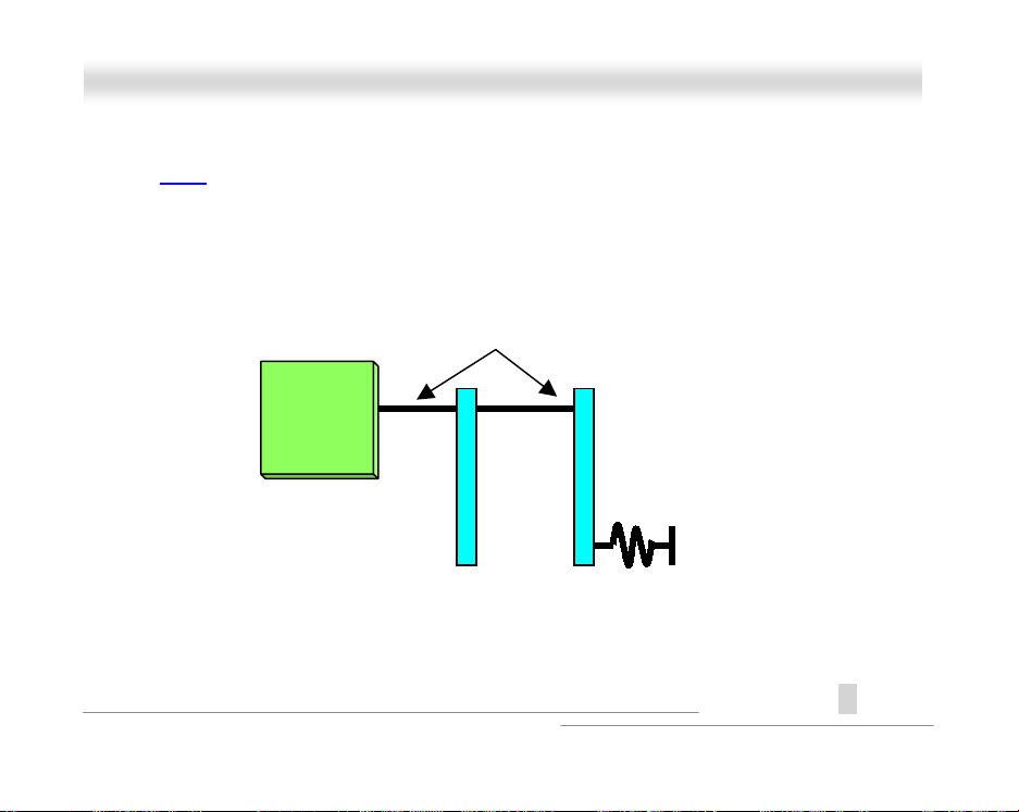
The RIMM
contain up to a maximum of 16 RDRAM devices. All RDRA M devices on a RIMM must have the
same timing characteristics. Therefore, empty RIMM sockets
RIMM modules, ( CRIMM )
modules have Rambus c hannel signals as their memory interface. A RIMM modul e may
MUST
which will be provided with motherboard.
Rambus Channel
MCH
RIMM1 RIMM2
18
Onnlliinnee MMaannuuaall
be populated with
Terminator
Continuity
A
Open
Page 19
O
X66CC--LL
AAX
Onnlliinnee MMaannuuaall
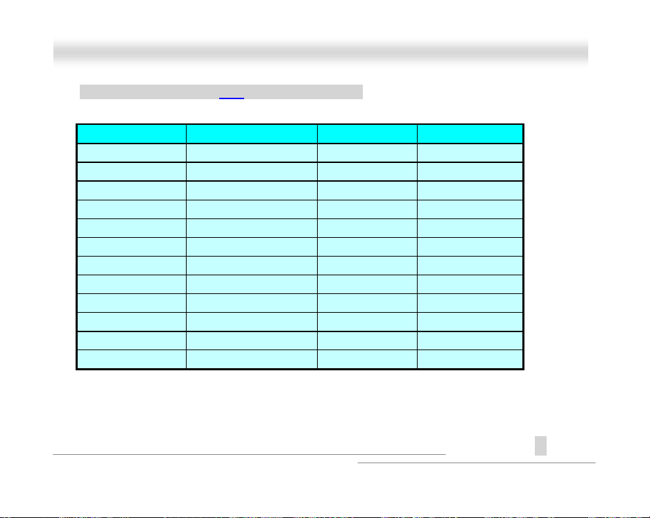
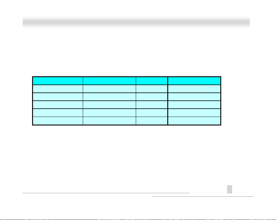
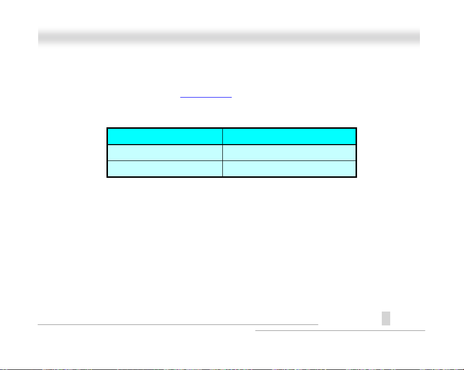
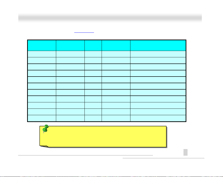
Setting RDRAM Speed
RDRAM speed means the data trans fer rate of RDRAM device, for example, PC800 RIMM has
800MBytes/sec data trans fer rate. Following table lists 5 kinds of CPU FSB and RDRAM speed
configurations that are s upported by Intel 820 chipset.
RDRAM Speed FSB Clock Ratio Suggested RDRAM
600MB/s = 100MHz 6x PC600
800MB/s = 100MHz 8x PC800
533MB/s = 133.3MHz 4x PC600
710MB/s = 133.3MHz 5.33x PC700
800MB/s = 133.3MHz 6x PC800
19
A
Open
Page 20
O
X66CC--LL
AAX
Onnlliinnee MMaannuuaall
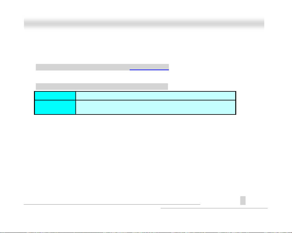
But with AOpen
expanded to almost unlimited. The RDRAM speed can be set by going into:
BIOS Setup > Frequency Control > RDRAM Speed
RDRAM Speed = CPU FSB Clock * RDRAM Ratio
RDRAM Ratio
CPU FSB
Full-range RDRAM Speed
4x, 4.5x, 5.33x, 6x, 7.11x and 8x
100.2, 105, 114, 120, 124, 128.5, 133.3, 133.9, 138, 143, 148, 150, 152.5,
155, and 160 MHz.
technology (patent pending) the combination can be
20
A
Open
Page 21
O
X66CC--LL
AAX
Onnlliinnee MMaannuuaall
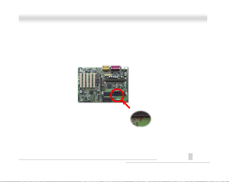
RRAAMM PPoowweerr LLEEDD
This LED indicates there i s power applies to memory. It is useful to check RAM power during
Suspend to RAM. Do not unplug RIMM when this LED is On.
21
A
Open
Page 22
O
K
V
V
V
R
X66CC--LL
AAX
Onnlliinnee MMaannuuaall
FFrroonntt PPaanneell CCoonnnneeccttoorr
Keylock
IDE LED
Speaker
1
+
+
+
+
SPWR
ACPI &
+
Power LED
+
Reset
22
1
GND
KEYLOC
+5
IDE LED
IDE LED
+5
+5
GND
NC
SPEAKE
SPWR
GND
ACPI & PWR LED
GND
+5V
NC
NC
GND
RESET
GND
A
Open
Page 23
O
X66CC--LL
AAX
Attach the power LED, keylock, speaker, and reset switch connectors to the corresponding pins. If
you enable Power Management > ACPI Function
flashing while the system i s in suspend mode.
Suspend Type ACPI LED
Power on Suspend (S1) Flashing for every second
Suspend to RAM (S3) Flashing for every 4 seconds
Locate the power switch cable from your ATX housing. It is 2-pin female connector from the
housing front panel. Plug this connector to the soft -power switch connector marked
in BIOS Setup, the ACPI & Power LED will keep
Onnlliinnee MMaannuuaall
.
SPWR
A
23
Open
Page 24
O
V
V
V
X66CC--LL
AAX
Onnlliinnee MMaannuuaall
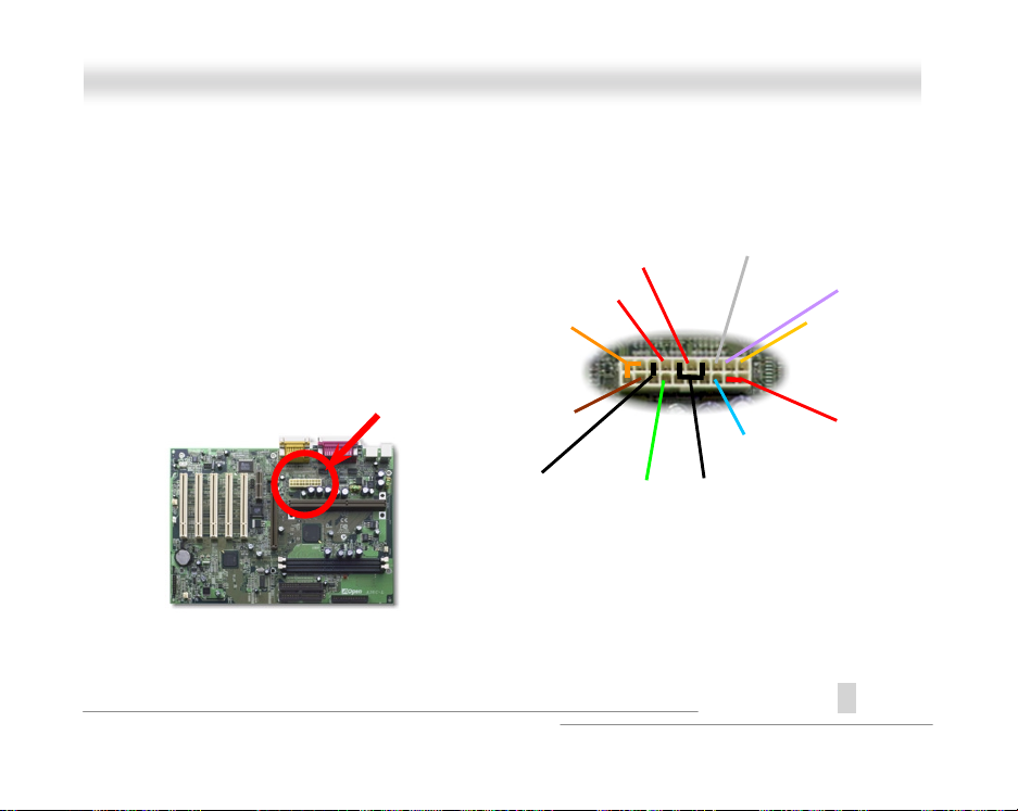
AATTXX PPoowweerr CCoonnnneeccttoorr
The ATX power supply uses 20-pin connector shown below. Make sure you plug in the right
direction.
+5V
+5
+3.3
PWOK
GND
24
-12
PWOK
-5V
GND
+12V
A
Open
5VSB
+5V
Page 25

O
X66CC--LL
AAX
Onnlliinnee MMaannuuaall
AACC PPoowweerr AAuuttoo RReeccoovveerryy
A traditional ATX system should remain at power off stage when AC power resum es from power
failure. This design is i nconvenient for a network server or workstation, without an UPS, that needs
to keep power-on. This motherboard implements an AC Power Auto Recovery f unction to solve this
problem. If BIOS Setup > Integrated Peripherals > AC PW R Auto Recovery is set to “Enabled” the
system will automatically power-on after AC power resumes.
25
A
Open
Page 26
O
X66CC--LL
AAX
Onnlliinnee MMaannuuaall
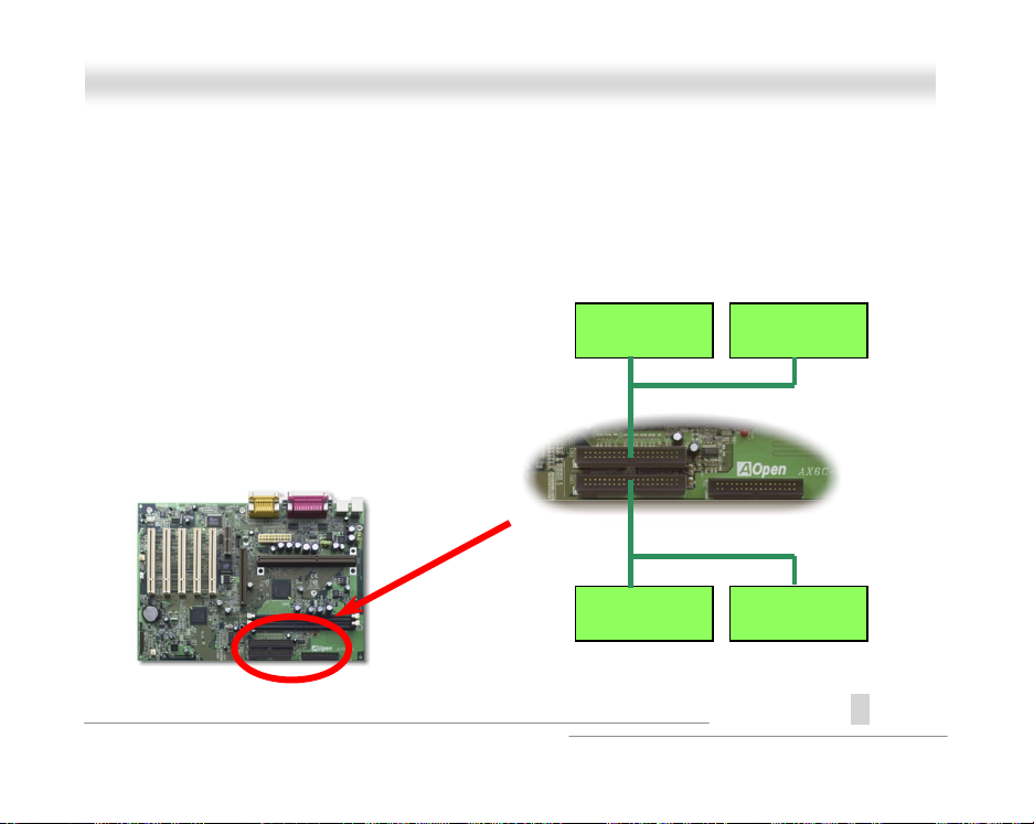
IIDDEE aanndd FFllooppppyy CCoonnnneeccttoorr
Connect 34-pin floppy cable and 40-pin IDE cable to floppy connector FDC and IDE connector
IDE1, IDE2
Wrong orientation m ay cause system damage.
. Pin1 of cable is normally marked with red color. Be careful of the pin1 orientation.
Slave (4th)
Master (3rd)
IDE2 (Secondary)
IDE1 (Primary)
Pin 1
FDC
Pin 1
Master (1st) Slave (2nd)
A
26
Open
Page 27
O
X66CC--LL
AAX
IDE1 is also known as the primary channel and IDE2 as the sec ondary channel. Each channel
supports two IDE devices t hat make a total of four devic es. In order to work together, the two
devices on each channel must be set differently to
hard disk or the CDROM. The setting as master or slave mode depends on the jumper on your IDE
device, so please refer to your hard di sk and CDROM manual accordingly.
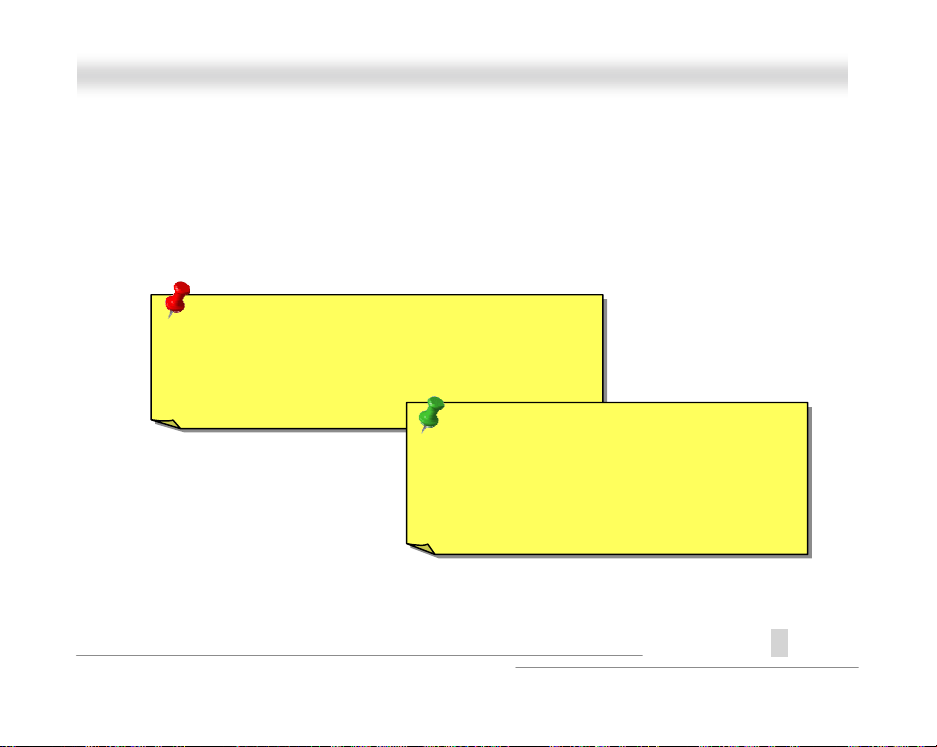
Warning: The specification of the IDE cable is a
maximum of 46cm (18 inches), make sure your cable
does not exceed this length.
Tip: For better signal quality, it is recommended
to set the far end side device to master mode
and follow the suggested sequence to install
your new device. Please refer to above diagram.
master
and
slave
Onnlliinnee MMaannuuaall
mode. Either one can be the
A
27
Open
Page 28
O
X66CC--LL
AAX
This motherboard supports ATA/66 IDE. Following table lists the transf er rat e of IDE PIO and DMA
modes. The IDE bus is 16-bit, which means every transfer is two bytes.
Mode Clock Period Clock
PIO mode 0 30ns 20 600ns (1/600ns) x 2byte = 3.3MB/s
PIO mode 1 30ns 13 383ns (1/383ns) x 2byte = 5.2MB/s
PIO mode 2 30ns 8 240ns (1/240ns) x 2byte = 8.3MB/s
PIO mode 3 30ns 6 180ns (1/180ns) x 2byte = 11.1MB/s
PIO mode 4 30ns 4 120ns (1/120ns) x 2byte = 16.6MB/s
DMA mode 0 30ns 16 480ns (1/ 480ns) x 2byte = 4.16MB/s
DMA mode 1 30ns 5 150ns (1/150ns) x 2byte = 13.3MB/s
DMA mode 2 30ns 4 120ns (1/120ns) x 2byte = 16.6MB/s
UDMA/33 30ns 4 120ns (1/120ns) x 2byte x2 = 33MB/s
UDMA/66 30ns 2 60ns (1/60ns) x 2byte x2 = 66MB/s
UDMA/100 20ns 2 40ns (1/40ns) x 2byte x2 = 100MB/s
Tip: To achieve the best performance of Ultra DMA/66 hard disks,
a special 80-wires IDE cable is required..
Count
Cycle Time Data Transfer Rate
Onnlliinnee MMaannuuaall
A
28
Open
Page 29
O
V
X
X
X66CC--LL
AAX
Onnlliinnee MMaannuuaall
1 2
9 10
NC
CIRRX
5VSB
NC
NC
connector and enable the infrared function from BIOS
IrDA
, make sure to have the c orrect orientation
Pin 1
29
A
Open
IIrrDDAA CCoonnnneeccttoorr
The IrDA connector can be conf i gured t o support wireless infrared module, with this module and
application software such as Laplink or Windows 95 Direc t Cabl e Connection, the user can transfer
files to or from laptops, notebooks, PDA devi ces and printers. This connec tor supports SIR
(115.2Kbps, 2 meters) and ASK-IR (57.6Kbps).
Install the infrared m odul e onto the
Setup > Integrated Peripherals > UA RT Mode Select
when you plug in the IrDA connector.
+5
NC
IRR
GND
IRT
Page 30
O
X66CC--LL
AAX
Onnlliinnee MMaannuuaall
WWOOMM ((ZZeerroo VVoollttaaggee WWaakkee oonn MMooddeemm))
This motherboard implements special circuit to support Wake On Modem , both internal modem
card and external box modem are supported. Since Internal modem card consumes no power when
system power is off, it i s recommended to use an internal modem. To use internal modem, connect
4-pin cable from
1
connector of modem card to the
RING
Pin 1
+5V Standby
NC
RING
GND
30
WOM
connector on the motherboard.
A
Open
Page 31

O
X66CC--LL
AAX
Onnlliinnee MMaannuuaall
WOM by External BOX Modem
Traditional Green PC suspend mode does not reall y t urn off t he system power supply, it uses
external box modem to trigger MB COM port and resum e back to active.
Motherboard
COM port
Box Modem
31
TEL Line
A
Open
Page 32

O
X66CC--LL
AAX
Onnlliinnee MMaannuuaall
WOM by Internal Modem Card
With the help of the ATX soft power On/Off, it is possible to have a system totally power off, and
wakeup to automatically answer a phone cal l as an answering machine or to send/recei ve a f ax.
You may identify whether or not your system is in true power off mode by c hecking to see if the fan
of your power supply is off. Both an external box modem and an i nternal modem card can be used
to support Modem Wake Up, but if you use an external modem, you have t o l eave your box modem
on.
Modem Card
With AOpen Motherboard plus AOpen Modem Card, the
power can be totally off
Motherboard
TEL Line
.
A
32
Open
Page 33

O
X66CC--LL
AAX
Onnlliinnee MMaannuuaall
WWOOLL ((WWaakkee oonn LLAANN))
This feature is very similar as Wake On Modem, but i t goes through local area network. To use
Wake On LAN function, you must have a network card with chipset that supports this feature, and
connect a cable from LA N card to motherboard W O L connector. The system identification
information (probably IP address) is stored on network card and becaus e there is a lot of traffic on
the Ethernet, you need to install a network management software, such as ADM, for the checking of
how to wake up the system. Note that, at least 600mA ATX standby current is required to support
the LAN card for this function.
+5V Standby
GND
LID
Pin 1
33
A
Open
Page 34

O
X66CC--LL
AAX
LAN Card
Motherboard
Ethernet
34
Onnlliinnee MMaannuuaall
A
Open
Page 35

O
X66CC--LL
AAX
Onnlliinnee MMaannuuaall
44XX AAGGPP ((AAcccceelleerraatteedd GGrraapphhiicc PPoorrtt))
This motherboard supports 4X AGP. AGP i s a bus interface designed for high-performance 3D
graphic and supports only memory read/write operation. One motherboard can only have one AGP
slot.
x 4 bytes x 2 = 528MB/s.
within one 66MHz clock cycle, s o that the data transfer rate is 66MHz x 4 bytes x 4 = 1056MB/s.
uses both rising and falling edge of the 66MHz clock, the data transfer rate is 66MHz
2X AGP
is still using 66MHz AGP clock but the it has 4 data transfers
4X AGP
35
A
Open
Page 36

O
X66CC--LL
AAX
Onnlliinnee MMaannuuaall
AAMMRR ((AAuuddiioo//MMooddeemm RRiisseerr))
AMR is a riser card that supports s ound or modem function. B ecause CPU computing power is
getting stronger, the digital processing job can be implemented in main chipset and share CPU
power. The analog conversion (CODEC
put on AMR card. This motherboard i mplements sound CODEC on board (can be disabled by
JP29), but reserve AMR slot for the option of modem funct i on. Note that you can still use PCI
modem card.
) circuit requires a different and separate circuit design, i t i s
A
36
Open
Page 37

O
X66CC--LL
AAX
This motherboard is AC97 sound onboard. That is , audio CODEC is put on motherboard and
modem function i s supported by AMR card.
Motherboard
Audio/Modem
Digital Controller
Chipset (I/O Hub)
Audio CODEC
AC97 Link
37
Onnlliinnee MMaannuuaall
Audio/Modem
Riser Card
Modem
CODEC
A
Open
Page 38

O
X66CC--LL
AAX
Onnlliinnee MMaannuuaall
Printer
Game Port
MIC
Line-In
Speaker
A
Open
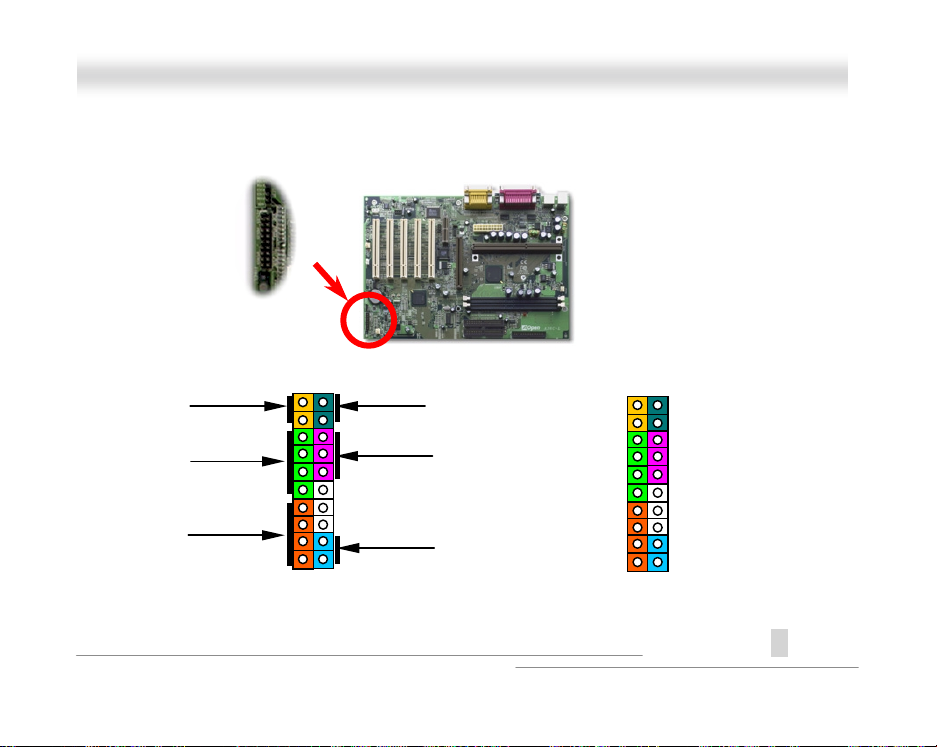
PPCC9999 CCoolloorr CCooddeedd BBaacckk PPaanneell
The onboard I/O devices are PS/2 K eyboard, PS/2 Mouse, serial ports COM1 and COM2, Print er,
two USB
panel of the housing.
, AC97 sound and Game port. The view angle of drawing shown here is from the back
PS/2 Mouse
USB
Speaker:
Line-In:
MIC:
Keyboard
To External Speaker, Earphone or Amplifier.
From signal source such as CD/Tape player.
From Microphone
COM1 COM2
38
Page 39

O
X66CC--LL
AAX
Onnlliinnee MMaannuuaall
JJPP2299 EEnnaabbllee//DDiissaabbllee OOnnbbooaarrdd SSoouunndd CChhiipp
This motherboard has AC97 sound onboard. JP29 is used to enable or disable onboard AD1881
CODEC
chip. If you select Disable, you can use your preferred AMR sound card.
1 2 3
Enable
1 2 3
Disable
39
A
Open
Page 40

O
X66CC--LL
AAX
Onnlliinnee MMaannuuaall
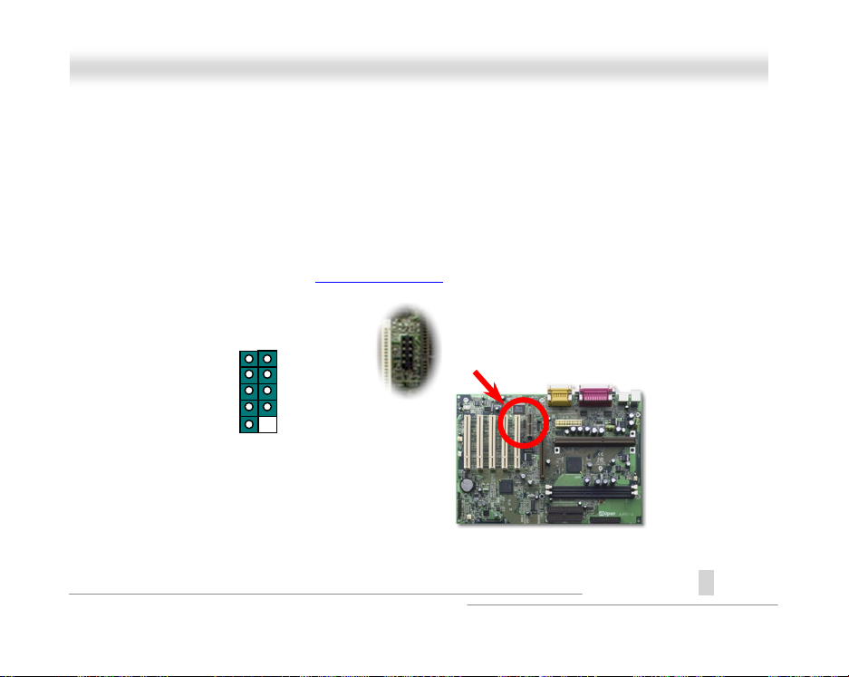
CCDD AAuuddiioo CCoonnnneeccttoorr
This connector is used to connect CD Audio cable from CDROM or DVD drive to onboard sound.
Pin 1
40
CD-IN
1 2 3
4
1 L
2 GND
3 GND
4 R
A
Open
Page 41

O
X66CC--LL
AAX
Onnlliinnee MMaannuuaall
MMooddeemm AAuuddiioo CCoonnnneeccttoorr
This connector is used t o connect Mono In/Mic Out cable from internal modem card t o onboard
sound circuit. The pin 1-2 is
standard for this kind of connector yet, only some internal modem cards i mplement this c onnector.
Pin 1
Mono In
, and the pin 3-4 is
41
Mic Out
. Please note that there is no
MODEM-CN
1 2 3
4
1 Mono In
2 GND
3 GND
4 Mic Out
A
Open
Page 42

O
X66CC--LL
AAX
Onnlliinnee MMaannuuaall
BBaatttteerryy--lleessss aanndd LLoonngg LLiiffee DDeessiiggnn
This Motherboard implements EEPROM and a special circuit that allo ws you t o save your current
CPU and CMOS Setup configurations without the need of a battery. The RTC (real time clock) can
also keep running as long as the power cord is pl ugged. If you lose your CMOS data by accident ,
you can just reload the CMOS configurations from EEPROM and the system will recover as usual.
Tip: For your convenience, this motherboard is still shipped
with one Lithium (CR-2032) battery in the battery socket. If
you prefer to use battery, you can keep it in the socket. The
RTC will still keep running even power cord is removed.
42
A
Open
Page 43

O
X66CC--LL
AAX
Onnlliinnee MMaannuuaall
Battery ATX standby power
RTC real time clock
EEPROM CMOS
Auto Swi tch
00:00:00
43
Auto switch to ATX standby
power as long as AC power
line is plugged. This smart
design increases battery l i f e
if you still plug battery on
motherboard.
Backup by EEPROM
A
Open
Page 44

O
X66CC--LL
AAX
Onnlliinnee MMaannuuaall
OOvveerr--ccuurrrreenntt PPrrootteeccttiioonn
The Over Current Protection was very popular im pl emented on ATX 3.3V/5V/12V switching power
supply. However, the new generation CPU uses different voltage that has regulator to transfer 5V to
CPU voltage (for example, 2.0V), and makes 5V over current protec tion useless. This motherboard
with switching regulator onboard support CPU over-c urrent protection, in conjunction with
3.3V/5V/12V power supply provide the f ul l l i ne over-current protection.
AT X
Switching
Power
Supply
12V (Protected by power supply)
3.3V (Protected by power supply)
5V (Protected by power supply)
Onboard
Power
Regulator
44
Over-Current
Protection
Circuit
CPU Core Voltage
A
Open
Page 45

O
X66CC--LL
AAX
Onnlliinnee MMaannuuaall
Note: Although we have implemented protection circuit try to prevent
any human operating mistake, there is still certain risk that CPU,
memory, HDD, add-on cards that install on this motherboard may be
damaged because of component failure, human operating error or
unknown nature reason. AOpen cannot guaranty the protection
circuit will always work perfectly.
45
A
Open
Page 46

O
X66CC--LL
AAX
Onnlliinnee MMaannuuaall
HHaarrddwwaarree MMoonniittoorriinngg
This motherboard implements a hardware monitoring system. As you turn on your system, this
smart design will continue to monitor your system’s working voltage, fan status and CPU
temperature. If any of t hese system’s status go wrong, there will be an alarm through the AOpen
Hardware Monitoring Utility
Fan
CPU
Power
to warn the user.
Fan Speed
CPU Temperature
CPU Voltage
System Voltage
46
Detection
Circuit
AOpen
HWMON
Utility
A
Open
Page 47

O
X66CC--LL
AAX
Onnlliinnee MMaannuuaall
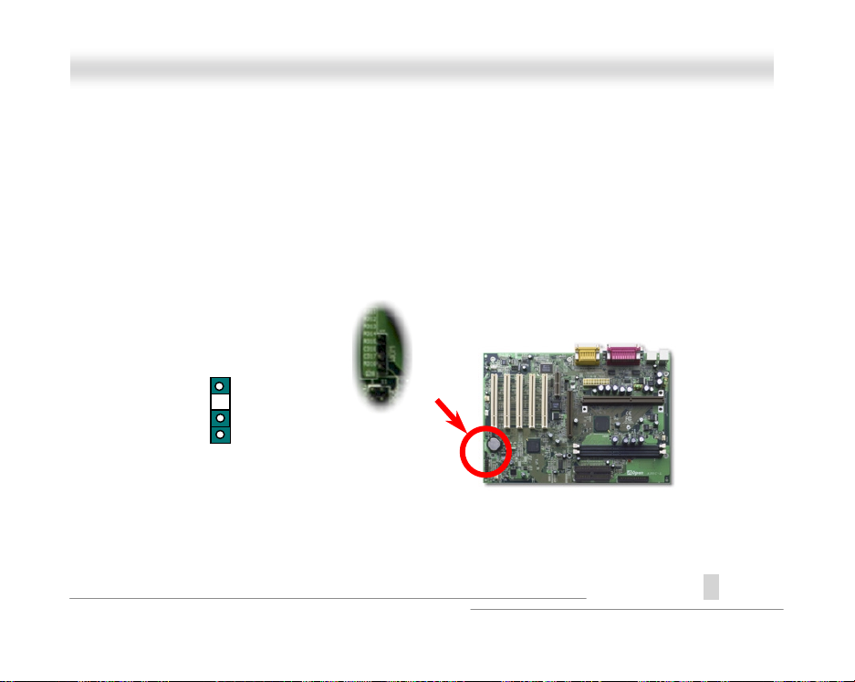
RReesseettttaabbllee FFuussee
Traditional motherboard has fuse for K eyboard and USB port to prevent over-current or short age.
These fuses are soldered onboard that when it i s broken (did the job to protect motherboard), user
still cannot replace it and the mot herboard is still malfunction.
With expensive Resett abl e Fuse, the motherboard can back t o normal function after fuse did the
protection job.
The green part at the left side of JP28.
A
Open
47
Page 48

O
X66CC--LL
AAX
Onnlliinnee MMaannuuaall
BBIIOOSS WWrriittee PPrrootteeccttiioonn
Recently, many viruses have been found that may dest roy bi os code and data area. This
motherboard implem ents two layers firewall to protect from unauthorized writing to BIOS. One is
hardware and the other is software
Hardware Protection
.
Access to BIOS
Software Protection
Flash ROM BIOS
A
48
Open
Page 49

O
X66CC--LL
AAX
Onnlliinnee MMaannuuaall
YYeeaarr 22000000 ((YY22KK))
Y2K is basically a problem of the identificat i on of year code. To save storage space, traditional
software uses only two digits for year i dentification. For example, 98 f or 1998 and 99 for 1999, but
00 will be confused with 1900 and 2000.
There is an RTC circuit (Real Time Clock) in conjunction with 128 bytes of CMOS RAM data in the
chipset of the motherboard. The RTC has only two digits and the CMOS has another 2 digits.
Unfortunately, this circuit’s behavior is like this 1997! 1998 ! 1999 ! 1900, that means it may
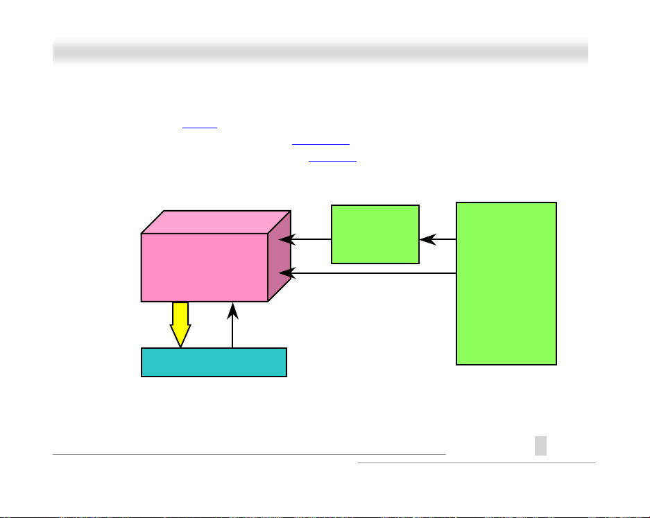
have the Y2K problem. Below is a di agram of how applications work with the OS, BI OS and RTC.
In order to keep the best compat ibility in the PC industry there is a rule that applications must call
the OS to get services and OS must call the BIOS , and then only BIOS is allowed to access the
hardware (RTC) directly.
A
Open
49
Page 50

O
X66CC--LL
AAX
Onnlliinnee MMaannuuaall
There is a Tick Routine (that goes live around every 50m sec) in the BIOS to keep record of
date/time information. In general the BIOS, this Tick Routine does not update the CMOS every time
because the CMOS is a very slow device which degrades system performance. The Tick Routine of
the AOpen BIOS has 4 digits for year coding, as long as applic ations and the operating system
follow the rule to get date/time information. There will be no Y2K problem (such as NSTL’s test
program). But unfortunatel y agai n, we found some test programs (such as Checkit 98) ac cesses
RTC/CMOS directly.
Operating System (such as Windows 98)
Applications
BIOS (Tick Routine)
RTC and CMOS data
50
A
Open
Page 51

AAXX66C
L
L
OOnnlliinne
e
MMaannuuaal
A
C--
l
LLooww EESSRR CCaappaacciittoorr
The quality of low ESR capacitor (Low Equivalent Series Resistance) during high frequency
operation is very important for stability of CPU power. The location of where to put these capacitors
is another know-how that requires experience and detail calculation.
Open
51
Page 52

O
X66CC--LL
AAX
The power circuit of the CPU core voltage must be checked to ensure syst em stability for high
speed CPUs (such as the new Penti um III, or when overclocki ng). A typical CPU core voltage is
2.0V, so a good design should control voltage between 1.860V and 2.140V. That is, the transient
must be below 280mV. Below is a timing diagram captured by a Digital Storage Scope, it shows the
voltage transient is only 143mv even when maximum 18A current i s applied.
Onnlliinnee MMaannuuaall
A
52
Open
Page 53

O
X66CC--LL
AAX
Onnlliinnee MMaannuuaall
LLaayyoouutt ((FFrreeqquueennccyy IIssoollaattiioonn WWaallll))
Note: This diagram is for example only, it may not be
exactly the same as this motherboard.
For high frequency operation, especial l y
overclocking, layout is the most important
factor to make sure chipset and CPU
working in stable condition. The layout of
this motherboard im pl ements AOpen’s
unique design called “ Frequency
Isolation Wall”. S eparating each critical
portion of motherboard into regions where
each region operates in a same or similar
frequency range to avoid crosst al k and
frequency interference between each
region’s operations and condition. The
trace length and route must be calculated
carefully. For example, the clock trace
must be equal length (not nec essarily as
short as possible) so that clock skew will
be controlled within few a pico second
12
(1/10
Sec)
53
A
Open
Page 54

O
X66CC--LL
AAX
Onnlliinnee MMaannuuaall
DDrriivveerr aanndd UUttiilliittyy
There are motherboard drivers and utilities included in A Open Bonus CD disc. You don’t need to
install all of them in order to boot your system. But after you finish the hardware installation, you
have to install your operation sys tem first (such as Windows 98) before you can install any drivers
or utilities. Please refer to your operation system’s installation guide.
54
A
Open
Page 55

O
X66CC--LL
AAX
Onnlliinnee MMaannuuaall
AAuuttoorruunn MMeennuu ffrroomm BBoonnuuss CCDD DDiisscc
You can use the autorun menu of Bonus CD disc. Choose the utility and driver and selec t model
name
A
55
Open
Page 56

O
X66CC--LL
AAX
Onnlliinnee MMaannuuaall
EElliimmiinnaattee ““??”” mmaarrkk ffrroomm WWiinnddoowwss 9955//9988
Windows 95/98 cannot recognize this chipset, because it was released before the Intel 820 chipset.
You can install the Intel INF Update Utility from the Bonus Pack CD disc autorun menu to eliminate
the “?” marks.
56
A
Open
Page 57

O
X66CC--LL
AAX
Onnlliinnee MMaannuuaall
IInnssttaalllliinngg OOnnbbooaarrdd SSoouunndd DDrriivveerr
This motherboard comes with an AD 1881 AC97 CODEC. You can find the audio driver from the
Bonus Pack CD disc autorun menu.
A
57
Open
Page 58

O
X66CC--LL
AAX
Onnlliinnee MMaannuuaall
IInnssttaalllliinngg BBuuss MMaasstteerr IIDDEE DDrriivveerr
It is necessary to install Bus Master IDE driver to support ATA/66 hard disk. If you need t hi s driver,
you can find it in the AOpen Bonus Pack
CD disc.
58
Note: Installing this Bus Master IDE driver
may cause Suspend to Hard Drive failure.
A
Open
Page 59

O
X66CC--LL
AAX
Onnlliinnee MMaannuuaall
IInnssttaalllliinngg HHaarrddwwaarree MMoonniittoorriinngg UUttiilliittyy
You can install Hardware Monitoring Utility to monitor CPU temperature, fans and system voltage.
You can find it in the AOpen Bonus Pack
CD disc.
59
A
Open
Page 60

O
X66CC--LL
AAX
60
Onnlliinnee MMaannuuaall
A
Open
Page 61

O
X66CC--LL
AAX
Onnlliinnee MMaannuuaall
61
A
Open
AACCPPII SSuussppeenndd ttoo HHaarrdd DDrriivvee
ACPI Suspend to Hard Drive is basicall y c ontrolled by Windows operation s ystem. It saves your
current work (system status, memory and screen image) into hard disk, and then the system can be
totally power off. Next time, when power is on, you can res ume your original work directly from hard
disk within few seconds without go through the Windows booting process and run your application
again. If your memory i s 64MB, normally, you need to reserve at least 64MB HDD space to save
your memory image.
Page 62

O
X66CC--LL
AAX
Onnlliinnee MMaannuuaall
When go into Suspend:
System
Image &
Status
When power-on next time:
System
Image &
Status
Save into
Restore within
seconds
62
Hard
Disk
Hard
Disk
A
Open
Page 63

O
X66CC--LL
AAX
System Requirement
Onnlliinnee MMaannuuaall
1.
AOZVHDD.EXE 1.30b
2. Delete
config.sys
or later.
and
autoexec.bat
.
Fresh installation of Windows 98 on a new system
1. Execute "
2. After Wi ndows 98' s installation is complete, go to the Control Panel > Power Management.
1. Clean boot into DOS and run AOZVHDD utility.
Setup.exe /p j
a. Set Power Schemes > System Standby to " Never" .
b. Click on "Hibernate" and select "Enable Hibernate S upport " then "Apply".
c. Click on the "Advanced" tab, you'll see "Hibernate" on "Power Buttons". Note that this option
will only be seen after step b mentioned above has been completed, otherwise only
"Standby" and "Shutdown" will be shown. Select "Hibernate" and "Apply".
a. If you assign the whole dis k to your Win 98 system (FAT 16 or FAT 32), please run
"
aozvhdd /c /file
if you have 64 MB DRAM and 16 MB VGA card instal l ed, the system needs at l east 80 MB
free space. The utility will locate the space automatically.
" to install Windows 98
". Please remember sufficient free space has to be reserved in the disk, e.g.
63
A
Open
Page 64

O
X66CC--LL
AAX
Onnlliinnee MMaannuuaall
b. If you assign an indi vi dual partition for Win 98, please run "
course, the system needs to provide unformatt ed an empty partition.
2. Reboot system.
3. You've already implemented ACPI Sus pend to-Hard Drive. Click "Start > S hut Down >
Standby" then the screen will go off immediately. And 1 minute or so will be taken for the
system to save what's in the memory to the hard drive; the larger the memory size the longer
this process will take.
64
aozvhdd /c /partition
". Of
A
Open
Page 65

O
X66CC--LL
AAX
Changing from APM to ACPI (Windows 98 only)
Onnlliinnee MMaannuuaall
1. Run "
Regedit.exe
a. Go through the following path
HKEY_LOCAL_MACHINE
b. Select "ADD Binary" and name it as "
c. Right click and select Modify, add "01" after "0000" to make it "0000 01" .
d. Save changes.
2. Select "Add New Hardware" under Control Panel. A l l ow Windows 98 to detect new hardware. (It
will find "
3. Reboot system.
4. Clean boot into DOS and run "AOZVHDD. E XE /C / F i l e"
ACPI BIO S
"
SOFTWARE
MICROSOFT
" and remove "
WINDOWS
CURRENT VERSION
DETECT
Plug and Play BIOS
ACPIOPTION
65
".
")
A
Open
Page 66

O
X66CC--LL
AAX
Changing from ACPI to APM
Onnlliinnee MMaannuuaall
1. Run "
Regedit.exe
a. Go through the following path
HKEY_LOCAL_MACHINE
SOFTWARE
b. Right click and sel ect "Modify, change "01" to "00" to make it "0000 02".
c. Save changes.
"
MICROSOFT
WINDOWS
CURRENT VERSION
DETECT
ACPI OPTION
Tip: "02" means Windows 98 is ACPI
acknowledged but the ACPI function is disabled.
66
A
Open
Page 67

O
X66CC--LL
AAX
2. Select "Add New Hardware" under Control Panel. A l l ow Windows 98 to detect new hardware. (It
will find "
3. Reboot system.
4. Run "Add New Hardware" again and it will find "Advanced Power Management Resource".
5. Click "OK".
Plug and Play BIOS
" and
remove "ACPI BIOS
Tip: Currently we found only ATI 3D Rage Pro
AGP card would support ACPI suspend to disk.
Please refer to AOpen web site for latest update.
67
")
Onnlliinnee MMaannuuaall
A
Open
Page 68

O
3.3
o
o
X66CC--LL
AAX
Onnlliinnee MMaannuuaall
AACCPPII SSuussppeenndd ttoo RRAAMM ((SSTTRR))
This motherboard supports ACPI Suspend to RAM function. With this function, you can resume
your original work directly from DRAM without goi ng t hrough the Windows 98 booting proces s and
run your application again. Suspend t o DRA M s aves your current work in the system memory, it is
faster than Suspend to Hard Drive but requi res power supplied to DRAM, while Suspend to Hard
Drive requires no power.
When go into Suspend:
System Image & Status
in the DRAM
When power-on next time:
System Image & Status
in the DRAM
Backuped by
V Power
Power back to
w
rk
68
Other System
Devices
Other System
Devices
Power loss
Power back to
w
rk
A
Open
Page 69

O
X66CC--LL
AAX
To implement ACPI Suspend to DRAM, please follow the proc edures as below:
Onnlliinnee MMaannuuaall
System Requirement
1. An ACPI OS is required. Currently, Windows 98 is the only choice. P l ease refer to ACPI
Suspend to Hard Drive
2. The Intel INF Update Utility must be installed properly.
of how to setup Windows 98 ACP I mode.
Procedures
1. Changed the following BIOS settings.
BIOS Setup > Power Management > ACPI Func tion : Enabled
BIOS Setup > Power Management > ACPI S uspend Type :S3.
2. Go to Control Panel > Power Management. Set “Power Buttons” to “St andby”.
3. Press power button or standby button to wake up the system .
69
A
Open
Page 70

O
X66CC--LL
AAX
Onnlliinnee MMaannuuaall
AAWWAARRDD BBIIOOSS
System parameters can be modified by going into BIOS Set up menu, this menu allows you t o
configure the system parameters and save the configuration into the 128 byte CMOS area,
(normally in the RTC chip or in the main chipset). To enter to BIOS setup menu
POST (Power-On Self Test)
screen is shown on your monitor.
Note: Because the BIOS code is the most often
changed part of the motherboard design, the BIOS
information contained in this manual may be
different with actual BIOS that come with your
motherboard.
70
, press <Del> when
A
Open
Page 71

O
X66CC--LL
AAX
Onnlliinnee MMaannuuaall
EEnntteerr BBIIOOSS SSeettuupp
Del
After you finish the s et ting of jumpers and connect correct cables. Power on and
enter the BIOS Setup, pres s <Del> during POST (Power-On Self Test)
"Load Setup Defaults
Warning: Please avoid of using "Load Turbo Defaults",
unless you are sure your system components (CPU,
DRAM, HDD, etc.) are good enough for turbo setting.
" for recommended opti mal performance.
71
. Choose
A
Open
Page 72

O
X66CC--LL
AAX
Onnlliinnee MMaannuuaall
CChhaannggee LLaanngguuaaggee
F3
You can change language by press <F3>. Depends on available BIOS space. The
possible languages are English, German, Japanese and Chinese.
A
Open
72
Page 73

O
X66CC--LL
AAX
Onnlliinnee MMaannuuaall
SSttaannddaarrdd CCMMOOSS FFeeaattuurreess
The "Standard CMOS Setup" sets the basic system parameters such as the date, time, and the
hard disk type. Use the arrow keys to hi ghl i ght an item and <PgUp> or <PgDn> to select the value
for each item.
73
A
Open
Page 74

O
X66CC--LL
AAX
Standard CMOS Features > Date
To set the date, highlight t he Date parameter. Press <PgUp> or <PgDn> to set the current dat e.
The date format is month, date, and year.
Standard CMOS Features > Time
To set the time, highl i ght the Time parameter. Press <PgUp> or <PgDn> to set the c urrent time in
hour, minute, and second format. The time is based on the 24 hour military cloc k.
74
Onnlliinnee MMaannuuaall
A
Open
Page 75

O
X66CC--LL
AAX
Standard CMOS Features > Primary Master
Standard CMOS Features > Primary Slave
Standard CMOS Features > Secondary Master
Standard CMOS Features > Secondary Slave
Type
None
Auto
Manual
This item lets you select the IDE hard disk parameters that your system supports.
These parameters are Size, Number of Cylinder, Number of Head, Start Cylinder for
Pre-compensation, Cyl i nder number of Head Landing Zone and Number of Sect or
per Track. The default setting is
the parameters of ins t al l ed HDD (Hard Di sk Drive) at POST
you prefer to enter HDD parameters manually, select Manual. The IDE CDROM is
always automatically detected.
Auto
75
,
Onnlliinnee MMaannuuaall
which enables BIOS to automatically detect
(Power-On Self Test). If
A
Open
Page 76

O
X66CC--LL
AAX
Standard CMOS Features > Drive A
Standard CMOS Features > Drive B
Drive A
None
360KB 5.25"
1.2MB 5.25"
720KB 3.5"
1.44MB 3.5"
2.88MB 3.5"
These items selec t the floppy drive type. The available sett i ngs
and types supported by the motherboard are l i sted to the left.
Standard CMOS Features > Video
Video
EGA/VGA
CGA40
CGA80
Mono
This item specifies the type of video card in use. The default
setting is
is almost usel ess and may be disregarded in the fut ure.
VGA/EGA
. Since current PCs us e VGA only, this function
76
Onnlliinnee MMaannuuaall
A
Open
Page 77

O
X66CC--LL
AAX
Standard CMOS Features > Halt On
Halt On
No Errors
All Errors
All, But Keyboard
All, But Diskette
All, But Disk/Key
This parameter enables you to c ontrol the system st ops in case of
Power-On Self Test (POST
) error.
77
Onnlliinnee MMaannuuaall
A
Open
Page 78

O
X66CC--LL
AAX
Onnlliinnee MMaannuuaall
AAddvvaanncceedd BBIIOOSS FFeeaattuurreess
This screen appears when you select the option "Advanced BIOS Features" f rom the main menu.
78
A
Open
Page 79

O
X66CC--LL
AAX
Advanced BIOS Features > Virus Warning
Virus Warning
Enabled
Disabled
Set this parameter t o Enabled to activate the warning mes sage.
This feature protects the boot sector and partition tabl e of your hard
disk from virus i ntrusion. Any attempt during boot up to write to the
boot sector of the hard disk drive stops the system and the
following warning message appears on the sc reen. Run an
anti-virus program to loc ate the problem.
Onnlliinnee MMaannuuaall
! WARNING !
Disk Boot Sector is to be modified
Type "Y" to accept write, or "N" to abort write
Award Software, Inc.
79
A
Open
Page 80

O
X66CC--LL
AAX
Advanced BIOS Features > Internal Cache
External Cache
Enabled
Disabled
Enabling this parameter activates the CPU internal cache
(currently, PBSRAM cache). Disabling the parameter slows
down the system. Therefore, we recommend that you leave it
enabled unless you are troubleshooting a problem.
Advanced BIOS Features > External Cache
External Cache
Enabled
Disabled
Enabling this parameter activates the secondary c ache
(currently, PBSRAM cache). Disabling the parameter slows
down the system. Therefore, we recommend that you leave it
enabled unless you are troubleshooting a problem.
Advanced BIOS Features > CPU L2 Cache ECC Checking
CPU L2 Cache ECC
Checking
Enabled
Disabled
This item lets you enabl e or di sable L2 Cache ECC
80
Onnlliinnee MMaannuuaall
checking.
A
Open
Page 81

O
X66CC--LL
AAX
Advanced BIOS Features > Processor Number Feature
Processor Number
Feature
Enabled
Disabled
This item is us ed t o enabl e or di sable Pentium III CPU
Number Feature.
Advanced BIOS Features > Quick Power On Self Test
Quick Power on Self
test
Enable
Disabled
This parameter speeds up POST
are normally checked.
81
by skipping some items that
Onnlliinnee MMaannuuaall
A
Open
Page 82

O
X66CC--LL
AAX
Advanced BIOS Features > First Boot Device
Advanced BIOS Features > Second Boot Device
Advanced BIOS Features > Third Boot Device
First Boot Device
A:
LS/ZIP
C:
SCSI
CDROM
D:
E:
F:
LAN
Disabled
This parameter allows you to specify the system boot up
search sequence. The hard disk ID are listed below:
C: Primary master
D: Primary slave
E: Secondary master
F: Secondary slave
LS: LS120
Zip: IOMEGA ZIP Drive
LAN: LAN card with boot ROM
82
Onnlliinnee MMaannuuaall
A
Open
Page 83

O
X66CC--LL
AAX
Advanced BIOS Features > Boot Other Device
Boot Other Device
Enabled
Disabled
This parameter allows you to enable other system boot up
devices that is not des cribed above.
Advanced BIOS Features > Swap Floppy Drive
Swap Floppy Drive
Enabled
Disabled
This item allows you to swap floppy drives. For example, if you
have two floppy drives (A and B), you can ass i gn the first drive
as drive B and the second drive as drive A or vi ce-versa.
Advanced BIOS Features > Boot Up Floppy Seek
Boot Up Floppy Seek
On
Off
Setting this param et er to enable/disable floppy seek t est
during Power On Self Test.
83
Onnlliinnee MMaannuuaall
A
Open
Page 84

O
X66CC--LL
AAX
Advanced BIOS Features > Boot Up NumLock Status
Boot Up NumLock
Status
On
Off
Setting this parameter to On enables the numeric f unction of
the numeric keypad. Set this parameter to Off to disregard the
function. Disabling t he numeric function allows you to use the
numeric keypad for curs or control.
Advanced BIOS Features > Typematic Rate Setting
Typematic Rate
Setting
Enabled
Disabled
Set this parameter to Enable/Disable the keyboard repeat
function. When enabled, continually holding down a key on
the keyboard will generate repeatedly keystrokes.
Advanced BIOS Features > Typematic Rate (Chars/Sec)
Typematic Rate
6, 8, 10, 12, 15, 20, 24,
30
This item allows you to control the speed of repeated
keystrokes. The default is 30 characters/sec.
84
Onnlliinnee MMaannuuaall
A
Open
Page 85

O
X66CC--LL
AAX
Advanced BIOS Features > Typematic Delay (Msec)
Typematic Delay
250, 500, 750, 1000
This parameter allows you to cont rol the delay time between
the first and the second keystroke (where the repeated
keystrokes begin).
Advanced BIOS Features > Security Option
Security Option
Setup
System
The
BIOS setup. A prompt asking you to enter your password
appears on the screen every tim e you boot the system.
The
To disable the security opti on, select Password Setting f rom
the main menu, don't t ype anyt hi ng and j ust press <Enter>.
option limits access to both the System boot and
System
option limits ac cess only to BIOS setup.
Setup
Advanced BIOS Features > OS Select for DRAM > 64MB
OS Select for DRAM
> 64MB
OS/2
Non-OS/2
Set to OS/2 if your system is ut ilizing an OS / 2 operat ing
system and has a m emory size of more than 64 MB.
85
Onnlliinnee MMaannuuaall
A
Open
Page 86

O
X66CC--LL
AAX
Advanced BIOS Features > Show Logo On Screen
Show Logo On Screen
Enabled
Disabled
This item lets you show or hide AOpen logo on the POST
screen.
86
Onnlliinnee MMaannuuaall
A
Open
Page 87

O
X66CC--LL
AAX
Onnlliinnee MMaannuuaall
AAddvvaanncceedd CChhiippsseett FFeeaattuurreess
The "Advanced Chipset Features" i ncludes settings for the chipset dependent features. Thes e
features are related to syst em performance.
Warning: Make sure you fully understand the
items contained in this menu before you try to
change anything. You may change the
parameter settings to improve system
performance. However, it may cause your
system to be unstable if the setting is not
correct for your system configuration.
A
87
Open
Page 88

O
X66CC--LL
AAX
Advanced Chipset Features > DRAM Data Integrity Mode
DRAM Data Integrity
Mode
ECC
Non-ECC
This lets you enable or disable memory ECC
ECC algorithm has the ability to detec t double bit error and
automatically correct single bit error.
Advanced Chipset Features > System BIOS Cacheable
System BIOS Cacheable
Enable
Disable
Allows the system BIOS to be cached to allow faster sys tem
performance.
Advanced Chipset Features > Video BIOS Cacheable
Video BIOS Cacheable
Enabled
Disabled
Allows the video BIOS to be ca ched to allow faster video
performance.
88
Onnlliinnee MMaannuuaall
function. The
A
Open
Page 89

O
X66CC--LL
AAX
Advanced Chipset Features > Video RAM Cacheable
Video RAM Cacheabl e
Enabled
Disabled
This item lets you cache Video RAM A000 and B000.
Advanced Chipset Features > Memory Hole At 15M-16M
Memory Hole At
15M-16M
Enabled
Disabled
This option lets you reserve s ystem memory area f or
special I/O cards. The chipset accesses code/data of these
areas from the I/O bus di rectly. Normally, these areas are
reserved for memory mapped I/O card.
Advanced Chipset Features > Delayed Transaction
Delayed Transaction
Enabled
Disabled
This item lets you control the Delayed Transaction function
of the ICH. This function is used to meet latency of PCI
cycles to or from ISA cycle.
89
Onnlliinnee MMaannuuaall
A
Open
Page 90

O
X66CC--LL
AAX
Advanced Chipset Features > AGP Aperture Size (MB)
AGP Aperture Size
(MB)
4, 8, 16, 32, 64, 128, 256
This item lets you determine the effective size of the AGP
Graphic Aperture.
90
Onnlliinnee MMaannuuaall
A
Open
Page 91

O
X66CC--LL
AAX
Onnlliinnee MMaannuuaall
IInntteeggrraatteedd PPeerriipphheerraallss
This submenu appears if you s el ect the option "Integrated Peri pheral s" from the main menu. This
option allows you to configure the I/ O features.
91
A
Open
Page 92

O
X66CC--LL
AAX
This page is the lower half of Integrat ed Peripherals submenu.
92
Onnlliinnee MMaannuuaall
A
Open
Page 93

O
X66CC--LL
AAX
Integrated Peripherals > On-Chip Primary PCI IDE
Integrated Peripherals > On-Chip Secondary PCI IDE
On-Chip Primary PCI
IDE
Enabled
Disabled
This parameter lets you enable or di sable the IDE device
connected to the primary IDE connector.
Integrated Peripherals > IDE Primary Master PIO
Integrated Peripherals > IDE Primary Slave PIO
Integrated Peripherals > IDE Secondary Master PIO
Integrated Peripherals > IDE Secondary Slave PIO
IDE Primary Master
PIO
Auto
Mode 1
Mode 2
Mode 3
Mode 4
Setting this item to
auto-detect function. The P IO mode specifies the data
transfer rate of HDD. For example: mode 0 data transfer rate
is 3.3MB/s, mode 1 i s 5.2MB/s, mode 2 is 8. 3MB/s, mode 3
is 11.1MB/s and mode 4 is 16.6MB/s. If your hard disk
performance becomes unstable, you may manual l y try the
slower mode.
93
activates the HDD speed
Auto
Onnlliinnee MMaannuuaall
A
Open
Page 94

O
X66CC--LL
AAX
Integrated Peripherals > IDE Primary Master UDMA
Integrated Peripherals > IDE Primary Slave UDMA
Integrated Peripherals > IDE Secondary Master UDMA
Integrated Peripherals > IDE Secondary Slave UDMA
IDE Primary Master
UDMA
Auto
Disabled
This item allows you to set the ATA/66
the hard disk drive connected to your primary IDE connector.
Integrated Peripherals > USB Controller
USB Controller
Enabled
Disabled
This item lets you enabl e or di sable the USB
94
Onnlliinnee MMaannuuaall
mode supported by
controller.
A
Open
Page 95

O
e
n
X66CC--LL
AAX
Integrated Peripherals > USB Keyboard Support
USB Keyboard Support
Enabled
Disabled
Note: You cannot use both USB driver and USB legacy keyboard at th
same time. Disable "USB Keyboard Support" if you have USB driver i
the operating system.
This item lets you enable or disable the USB keyboard driver
within the onboard BIOS. The keyboard driver simulates
legacy keyboard comm and and l e t you use USB keyboard
during POST or after boot if you don't have USB driver in the
operating system.
Integrated Peripherals > Init Display First
Init Display First
PCI Slot
AGP
If you installed a PCI V GA card, this item l ets you decide
which one is the initial dis pl ay card.
95
Onnlliinnee MMaannuuaall
A
Open
Page 96

O
X66CC--LL
AAX
Integrated Peripherals > AC97 Audio
AC97 Audio
Auto
Disabled
This item is used to enable or disable the onboard audio.
Integrated Peripherals > AC97 Modem
AC97 Modem
Auto
Disabled
The item is used to enable or di sable the AC97 modem. If
disabled, an AMR modem card can’t work properly.
Integrated Peripherals > IDE HDD Block Mode
IDE HDD Block Mode
Enabled
Disabled
This feature enhances disk performance by allowing
multi-sector dat a transfers and eliminates the interrupt
handling time for each sector. Most IDE drives, except with
old designs, can support t hi s feature.
96
Onnlliinnee MMaannuuaall
A
Open
Page 97

O
X66CC--LL
AAX
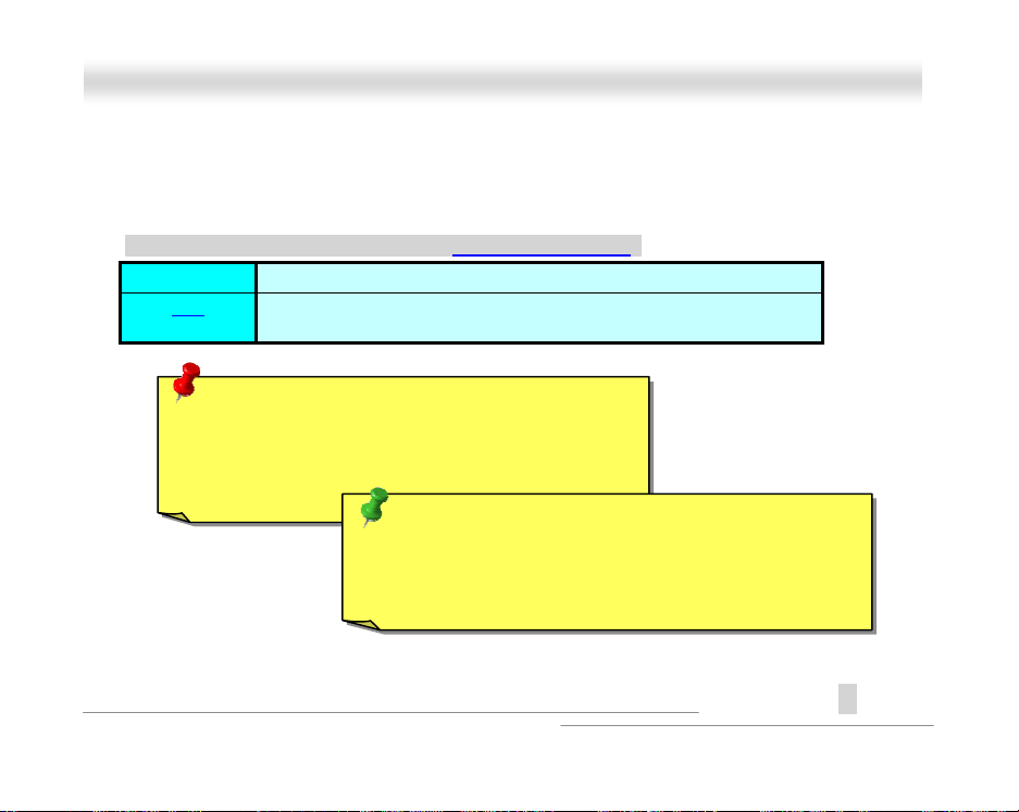
Integrated Peripherals > Power On Function
Power On Function
Any Key
Button Only
Keyboard 98
Password
Hot Key
Mouse Left
Mouse Right
This item is used to select Wake on Keyboard/Mous e mode.
Any Key:
clicking any key.
Button Only:
up your system by power button only.
Keyboard 98:
system by power button and the “Wake” key on Keyboard 98.
Password:
system can only be powered on through the pres et keys (like a
password).
Hot Key:
hot key from “Hot Key P ower On” it em.
Mouse Left:
clicking left mouse button twice succ essively.
Mouse Right:
clicking right mouse button twice succes sively.
This function allows you wake up the sys t em by
Disable Wake on KB/MS f unction. You can boot
If selecting this option, you can boot up the
Disable the function of power button and l et the
If selecting thi s option, you also need to specify the
This function allows you wake up the sys t em by
This function allows you wake up the system by
97
Onnlliinnee MMaannuuaall
A
Open
Page 98

O
u
t
s
X66CC--LL
AAX
Note:
"# Whenever you change this item, it will only take effect after yo
restart the system and successfully boot the Windows or DOS.
"# To implement Wake on Keyboard/Mouse function, you must se
JP28 to Enabled.
"# Wake on Mouse function applies to PS/2 mouse only.
"# If you set a password but forget it, please clear CMOS.
"# If you want to use Wake on Mouse function in DOS, it i
necessary to install the DOS driver of the mouse.
Integrated Peripherals > KB Power On Password
KB Power On Password
You can specify 1-5 keys as a password.
98
Onnlliinnee MMaannuuaall
A
Open
Page 99

O
X66CC--LL
AAX
Integrated Peripherals > Hot Key Power On
Hot Key Power On
Ctrl-F1, Ctrl-F2, Ct rl-F3,
Ctrl-F4, Ctrl-F5, Ct rl-F6,
Ctrl-F7, Ctrl-F8, Ct rl-F9,
Ctrl-F10, Ctrl-F11,
Ctrl-F12
If you select “Hot Key” option in “Power On Function” Item,
you need to specify a hot key here.
Integrated Peripherals > Onboard FDC Controller
Onboard FDC
Controller
Enabled
Disabled
Setting this parameter to
your floppy disk drives to the onboard floppy disk
connector instead of a separate controller card. Change
the setting to Disabled i f you want to use a separate
controller card.
99
Enabled
Onnlliinnee MMaannuuaall
allows you to connect
A
Open
Page 100

O
X66CC--LL
AAX
Integrated Peripherals > Onboard Serial Port 1
Integrated Peripherals > Onboard Serial Port 2
Onboard Serial Port 1
Auto
3F8/IRQ4
2F8/IRQ3
3E8/IRQ4
2E8/IRQ3
Disabled
This item allows you to assign address and interrupt for
the board serial port. Default i s
Note: If you are using network card,
make sure that the IRQ do not conflict.
100
Onnlliinnee MMaannuuaall
.
Auto
A
Open
 Loading...