

Page 1
AOC TV2764W-
2E
S
S
E
E
R
R
VII
V
C
C
E
E
M
M
A
A
N
N
U
U
A
A
LCD TV MONITOR
TV2764W-2E
L
L
THESE DOCUMENT S ARE F OR REPAIR SERVICE INFORMATION ONLY. EVERY REASONABLE EFFORT
HAS BEEN MADE TO ENSURE THE ACCURACY OF THIS MANUAL; WE CANNOT GUARANTEE THE
ACCURACY OF THIS INFORMATION AFTER THE DATE OF PUBLICATION AND DISCLAIMS RELIABILITY FOR
CHANGES, ERROR S OR O MI S SIO NS.
MANUFACTURE DATA :AUG.-23-2005 Revision:A00
- 0 -
Page 2

1
9
9
9
9
TABLE OF CONTENTS
PAGE
1. SPECIFICATIONS FOR LCD TV ...........................................................…………...…..
1-1 GENERAL SPECIFICATIONS …................................................…………....…. 2
1-2 OPERATING INSTRUCTIONS ..................................................…………...………….. 3
1-2-1 USE OF THE REMOTE CONTROL ..................................…………....…………… 3
1-1-2 TO USE THE MENUS .............................................…… ……. ……… … … ...… 5
1-3 LCD TV DESCRIPTION ..................................................…………...………….. 8
1-4 INTERFACE CONNECTOR ......................................................………….....…. 8
2. PRECAUTION AND NOTICES .................................................……………..…………
2-1 ASSEMBLY PRECAUTION ..........................................................…………..….
2-2 OPERATIONG PRECAUTION .....................................................…………..….
2-3 STORAGE PRECAUTION …........................................................…………..….
2-4 HIGH VOLTAGE WARNING .......................................................…………...….
3. D-SUB PIN DISTRIBUTION .........................................................................……………
3-1 FACTORY PRESET DISPLAY MODES …………………………………….…..... 11
4. ADJUSTMENT .........................................................................……………...…………
2
9
10
12
4-1 ADJUSTMENT CONTROL FUNCTION ..............................................……….... 12
4-2 ADJUSTMENTS METHOD .............................................................………….... 12
4-3 FRONT PANEL CONTROL KNOBS ................................................…………... 12
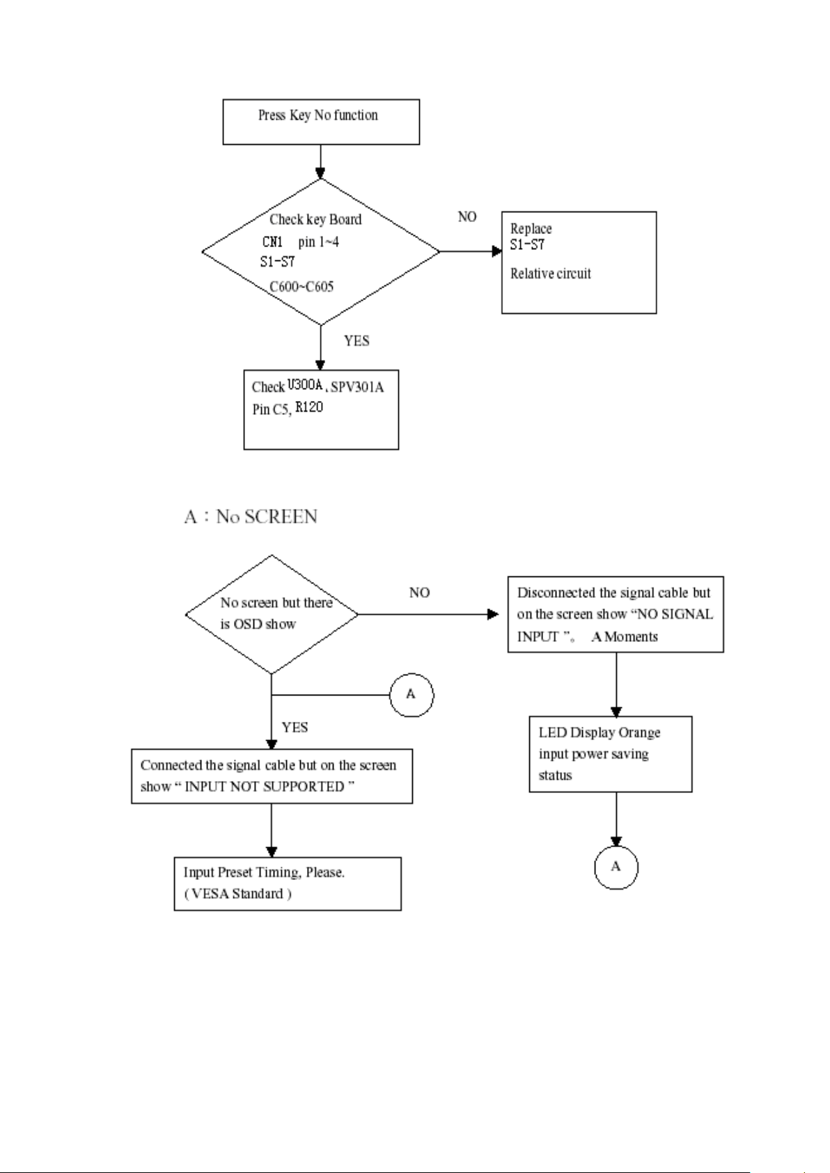
5. TROUBLE SHOOTING CHART ................................................................………….....
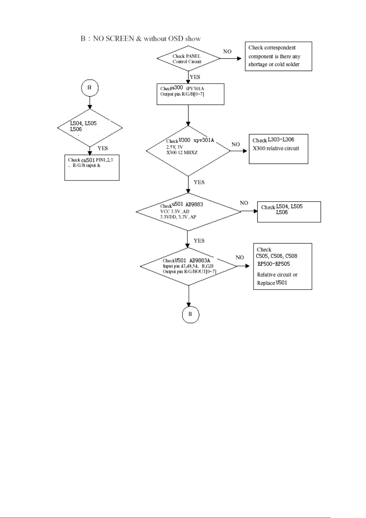
5-1 PANEL CONTROL CIRCUIT TROUBLE SHOOTING ………………………… 13
5-2 MAIN BOARD POWER VCC TROUBLE SHOOTING ………………………… 14
5-3 REMOTE CONTROL BLOCK TROUBLE SHOOTING .………………………. 14
5-4 KEY BOARD CONTROL BLOCK TROUBLE SHOOTING ……………………… 15
5-5 PC CONTROL BLOCK TROUBLE SHOOTING ………………………………. 15
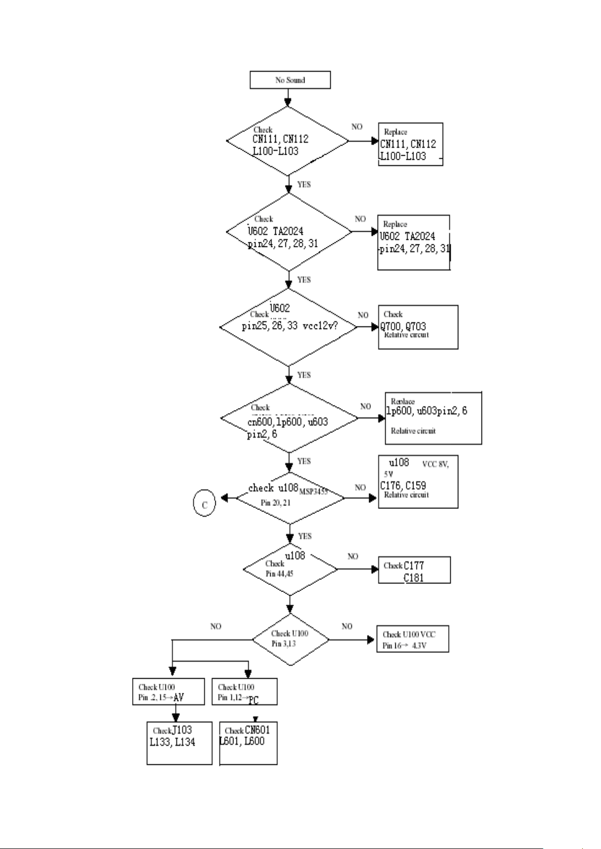
5-6 AUDIO CONTROL BLOCK TROUBLE SHOOTING ..............................……… 17
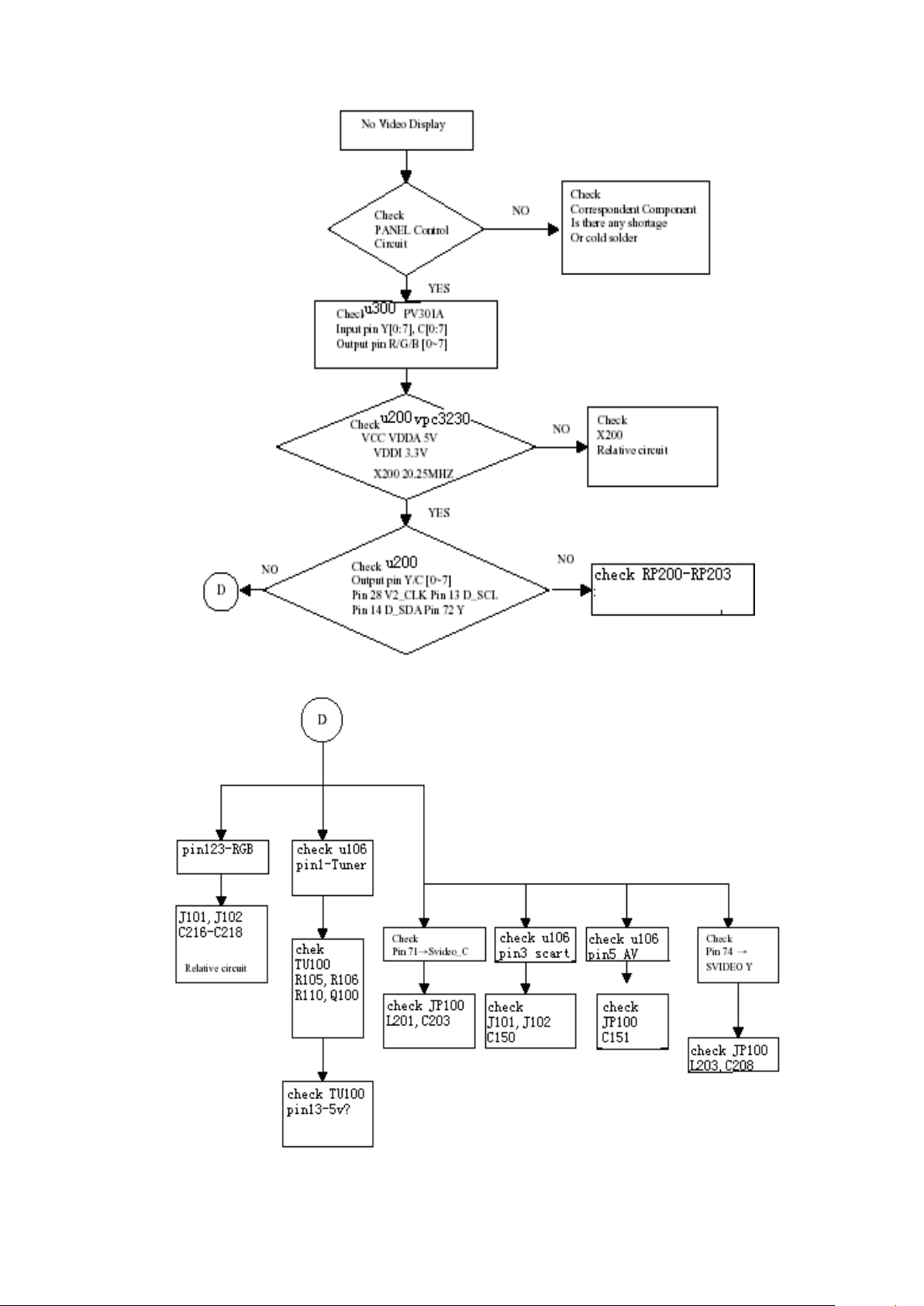
5-7 VIDEO CONTROL BLOCK TROUBLE SHOOTING ......................................... 18
6. WHITE-BALANCE, LUMINANCE ADJUSTMENT ……………………………………...
7. SOFTWARE FLOW CHART ……………………………………………………………...
8. PARTS LISTING OF CABINET (BOM) …………………………………………………...
9. PCB LAYOUT ...………………………………………...........................……………...…
9-1 MAIN BOARD ……………………………………………….. 47
9-2 ADAPTER BOARD PCB ……………………………………………….. 48
9-3 DC TO DC BOARD PCB ...……………………………………………….. 49
13
19
21
24
47
9-4 HEADPHONE BOARD PCB …………………………………………….. 49
9-5 IR BOARD PCB ...…………………………………….. 49
9-6 KEY BOARD PCB ……………………………………………………… 49
10. SCHEMATIC ........................................................………………………………...
10-1 MAIN BOARD ……………………………………………..… 50
10-2 POWER BOARD ……………………………………………..… 61
11. BLOCK DIAGRAM ........................................................…………………………...
12. DEXPLDING DIAGRAM ...........................................………………………………...
50
53
64
Page 3
2
1. SPECIFICATIONS FOR LCD TV
PAL B/G, D/K, I and SECAM L/L’
Full Channel with Electroni c PLL Tuner
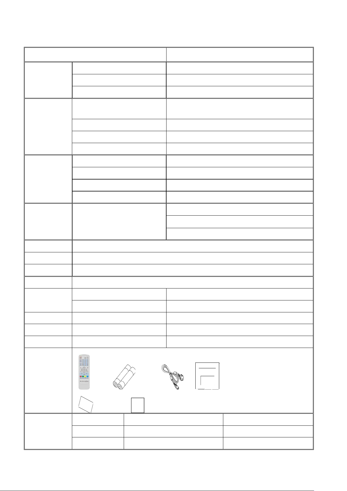
Remote Controller, Batteries (x2), AC Power Cord, User Manual,
1-1 GENERAL SPECIFICATIONS
Items Specifications
Screen Size 27” TFT-LCD
LCD Panel
TV Function
PC Input
Audio Output Audio Output: L / R
Other Function PIP (in PC Mode)
Aspect Ratio 16:9
Display Area (opening) 603.22mm x 341.98mm (H x V)
TV Tuning System
Sound System Nicam / A2
Teletext Yes
Color systems PAL / SECAM / NTSC
Signal Input Analog: D-Sub 15 pin (detachable cable)
PnP compatibility DDC 2B
Recommended Analog 1024x 768(60Hz)
Input Audio Headphone Mini-jack for stereo (3.5ø)
(Multi-Europe)
Speaker (built-in): Two 5 watt speakers
Headphone Mini-jack for stereo (3.5ø)
Line Output (SCART L/R)
OSD language English / French / Germany / Italian / Spanish / Portuguese
Table Stand Included
Wall Mount VESA 100 x 100 mm
Power Supply AC100V~240V, 50/60Hz
Power
Power Consumption 100W. max <140W
Panel Tilt Forwards/ Backwards/ Rotation -5° / +20° / ± 35°
Dimension W x H x D (with stand) 898 x 470 x 287 (mm)
Weight (net) Kg (w/o Accessories) 13.4 KG
Accessories
Warranty St atement, Quick Setup Card
SCART (RGB+CVBS) x 1,CVBS x 1 Audio L/R x 2
Video Inputs
RCA CVBS (Composite) x 1 Audio L/R x 1
S-Video S-Video x 1 Share with CVBS (RCA)
Page 4
3
1-2 OPERATING INSTRUCTIONS
POWER:
VOL
CH
MENU
SLEEP
key repeatedly to select the
runs from 0, 30, 60, 90,120
selected after the display has
0~9 DIGIT BUTTONS
TV/VIDEO
Select your input source: press
MUTE
PRE-CH
SOUND
PC
DISPLAY
SIZE
SWAP
PIP/POP
SUBPAGE
Teletext function and buttons will be described on next page.
1-2-1 USE OF THE REMOTE CONTROL
Press to turn on/off the T V. The TV
is never completely powered off
unless it is physically unplugged.
Press or (or MENU ▲ or ▼
button) buttons to scroll through the
channels.
Press + or – (or MENU or
button) to increase or decr ease the
volume.
Select your input source to PC.
Press this key to display:
(1) the channel number when
watching a TV program.
(2) the input source when
watching an AV program.
Temporarily interrupt the sound
or restore it.
Teletext Sub-page function.
To select a TV channel.
To display the previously selected
With this key you can set a time
period after which the TV should
switch itself to standby. Press the
number of minutes. The counter
minutes. The tim er begins to count
down from the number of minutes
disappeared.
Press to swap the two screens
when POP is work (option).
Press this key to display
main menu.
Press this key repeatedly
to select desired picture
format (4:3, CINERAM A,
repeatedly to select TV, AV, S-VIDEO
or SCART m ode, accordin g to where
you connected your external source.
To select Mono/ Stereo /Dual from TV
RF input.
Press this key to display PIP screen
(only in PC mode).
POP is not available on this model.
Page 5
4
TELETEXT
Teletext is an informat ion service organized lik e a magazine, which is provided by some T V stations in addition to
regular television broadcasting.
TELETEXT
Press TELETEXT. The Teletext screen appears.
To turn off the Teletext mode, press TELETEXT again.
MIX
Press MIX to superimpose the teletext over a normal
broadcast picture. Press again to return to Teletext mode.
SIZE
Press SIZE rep eatedly to display the upper teletext part,
the lower teletext part and then to return to the normal.
RED / GREEN / YELLOW / BLUE
Use the COLOURED BUTTONS to operate the Teletext
screen.
INDEX
Press INDEX to return to the main index page.
SUBTITLE
Press to select the next page marked as a subtitle page and
request it as the display page.
HOLD
Press HOLD to hold the Teletext page when viewing
information. Press again to return to automatic page update.
REVEAL
Press REVEAL to displa y reveal hidden words e.g. qu iz page
answers. Press again to hide.
PAGE SELECTION
Page can be selected in two ways.
a. Press ▼or ▲ to increase or decrease the page number by one.
b. By entering the page number, using digit buttons 0~9.
SUBPAGE ACCESS
When Teletext information exceeds more than one page. Press SUBPAGE fir st then select the required
page number using digit buttons 0~9.
Page 6
5
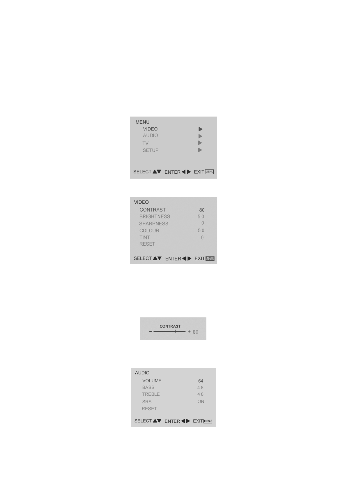
1-2-2 To use the menus
1. Press the MENU button repeatedly to display each menu.
2. Use the cursor up/down to select a menu item or adjust the setting of Menu item.
3. Use the cursor left/right to enter a submenu or enable the function.
4. Press the MENU button to exit the menu.
MAIN MENU
Press the MENU button into the main OSD (On Screen Display). Adjust item include VIDEO, AUDIO, TV (only in the
TV mode), PC and PIP (only in the PC mode) and SETUP.
VIDEO Adjust
1. CONTRAST, BRIGHTNESS, COLOUR and TINT are adjusted from 0 to 100.
2. SHARPNESS is adjusted from -5 to +5.
You can adjust picture contrast, brightness, color, tint and sharpness to the levels you prefer.
3. RESET is set up to default value.
Note: TINT only work in NTSC video signal input.
When adjust any item sub-OSD will show up like this.
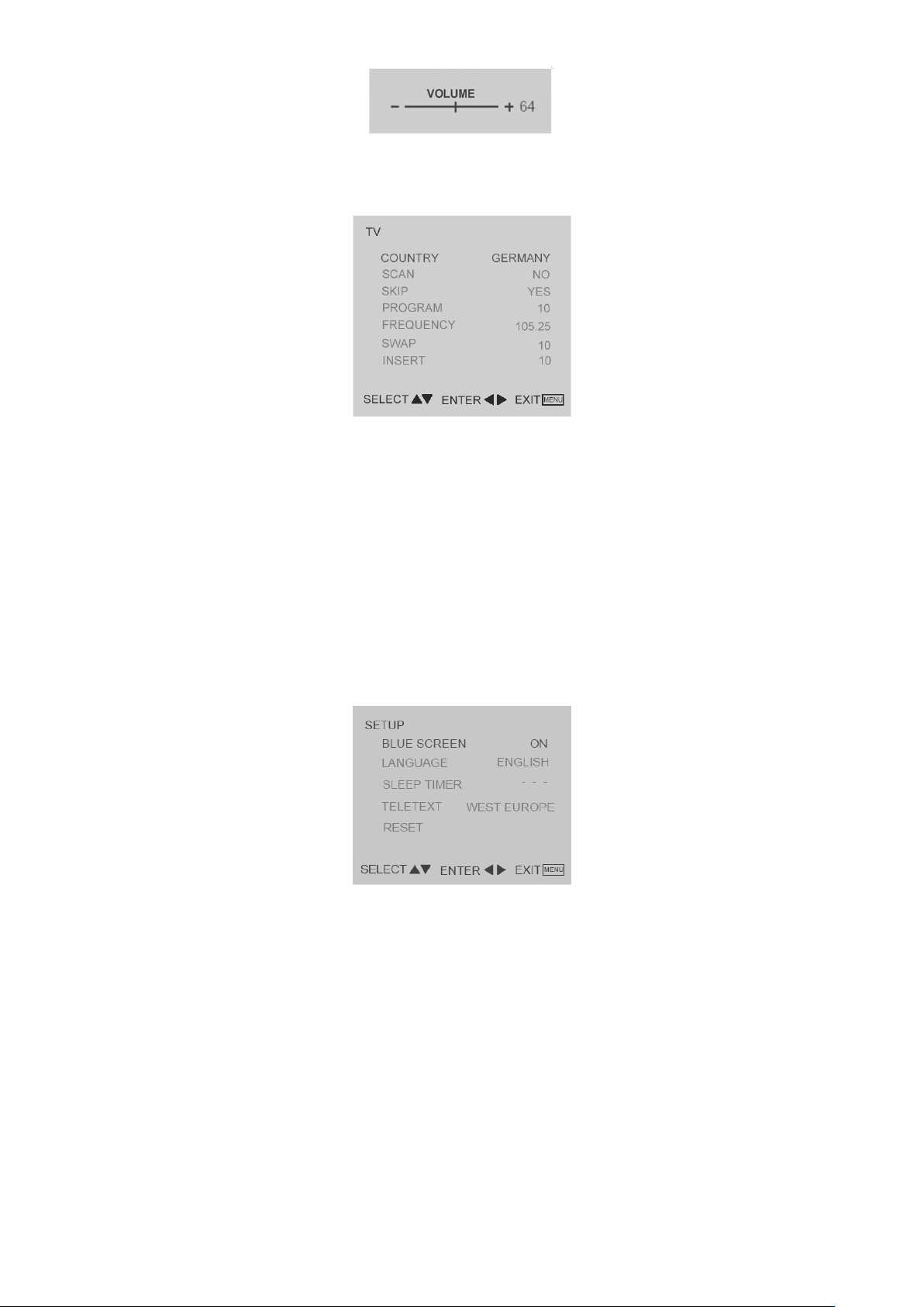
AUDIO Adjust
1. VOLUME is adjusted from 0 to 100.
2. BASS and TREBLE are adjusted from 0 to 100.
3. SRS for turn on / off SRS function. SRS is an audio tec hno logy which improves sound qualit y.
You can adjust picture Volume, Bass and Treble to the levels you prefer.
Page 7
6
TELETEXT
TV
When adjust any item sub-OSD will show up like this.
Quick Installation
1. Use COUNTRY to select your country first.
2. Move to SCAN and scan the program.
3. After scan finished, you can use SKIP to skip the unlike program.
PROGRAM Editing
Using PROGRAM, FREQENCY, SWAP, and INSERT for program edit.
1. Move to PROGRAM, select the program you want to edit
2. Move to FREQENCY, use RIGHT or LEFT button for program search.
3. User can use SWAP for program swap.
4. Use INSERT to insert current program into selected position.
SETUP
1. BLUE SCREEN for when no video in put s creen will be blue or bl ank. I f it ’s ON, the scr een wil l be in blu e. If it ’s
OFF, the screen will be blank. Preset is ON.
2. LANGUAGE for different language OSD MENU. Preset is English.
3. SLEEP TIM ER is for set a time period af ter whic h th e T V s hould s wit ch its e lf to s tandby. The counter runs f rom
0 > 30 > 60 > 90 > 120 minutes.
4.
The following character sets are available: WEST EUROPE, EAST EUROPE, ARABIC, GREEK, CYRILLIC.
The character set determines how characters are displayed on Teletext screen.
5. RESET is set up to default value of BLUE SCREEN and SLEEP TIMER.
Note: To view the remaining time, pres s the SLEEP button onc e. To cancel the sleep time, repeatedly press the
SLEEP butto n unt il a notice APPEAR S. If you t urn the TV off after sett in g t he s l eep time, the setting w i ll be er ased.
Set it again.
: Using / buttons, select the character set that wil be used for Teletext on this channel.
Page 8
7
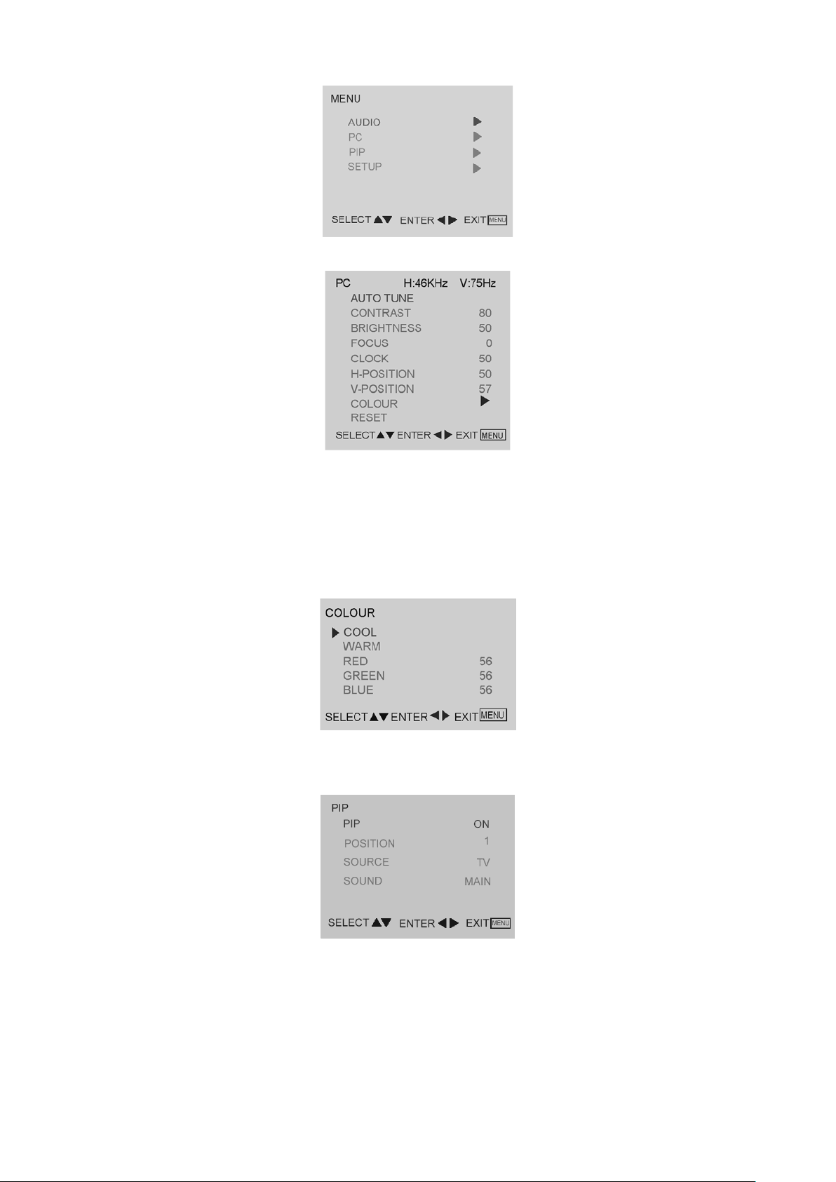
PC Setup
PC Adjust
1. AUTO TUNE is the function auto-sizing for VGA input.
2. CONTRAST, BRIGHTNESS, FOCUS, CLOCK, H-POSITION, V-POSITION and COLOUR are the functions for
PC adjustment.
COLOUR
Colour for you can adjust the colour temperature you pref e r.
PIP
1. PIP for turn on / off small picture function.
2. POSITION for change the position of small picture.
3. SOURCE for select video source of small picture.
4. SOUND for select audio source form MAIN (PC) or SUB (Video).
Page 9
8
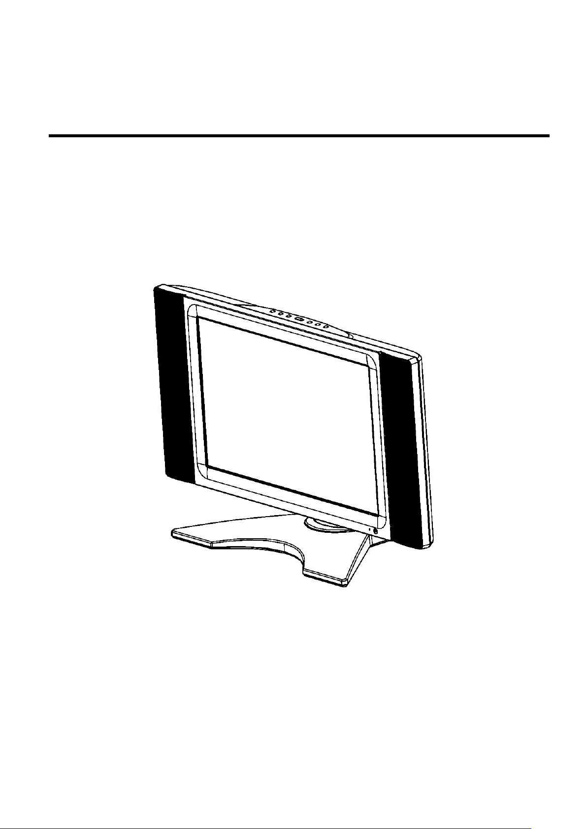
1-3 LCD TV DESCRIPTION
Molded-over, shielded, 15-pin subminiature D male plug with75Ω
ompliance with PC 99 Color Theme. Refer to
D male plug with75Ω impedance. (black)
Molded-over, shielded, 21-pin subminiature D male plug with75Ω
impedance.(black)
The LCD TV will contain a main board (inc lude audio) , a switching po wer board (inc lude an inverter board),
an IR board, a function k eyboard, an I/O board and a Headphone board. T he main board and pow er board
will house the flat panel to control logic I2C bus, DDC, brightness control logic for LCD panel, DC-DC
conversion to sup ply the appropri ate power to the whole boar d and transm itting TTL lev el signals into LCD
Module to drive the LCD display circuit.
The inverter board will drive the fourteen CCFLs (Cold Cathode Fluorescent Tube).
The switching power board will pro vides the power O N/OFF to contr ol the TV and con trol LED indicator for
DPMS.
The function keyboard and Remote Control will provide the OSD control signal to the Main Board.
1-4 INTERFACE CONNECTORS
All signal connections to this product are via external connectors locating at the rear of the product. The
specifications of these connectors are listed in the following table.
External Connector Specification
AC-In AC Jack 3-male receptacle
RGB Input
Audio Input (L/R) RCA Jack (White/Red)
Audio Input 3.5 Mini Jack for PC Audio
Headphone Output 3.5 Mini Jack
Composite Video RCA Jack (Yellow)
CVBS Input
S Video 4 Din Jack
impedance. C
Appendix B for pin la yout. Molded-over, shielded, 21-pin subminiature
Page 10

9
2. PRECAUTIONS AND NOTICES
2-1 ASSEMBLY PRECAUTION
(1) Please do not press or scratch LCD panel surface with anything hard. And do not soil LCD panel surface
by touching with bare hands (Polarize film, surface of LCD panel is easy to be flawed)
In the LCD panel, the gap between two glass plates is kept perfectly even to maintain display
characteristic and reliability. If this panel is subject to hard pressing, the following occurs:
(a) Uniform color (b) Orientation of liquid crystal becomes disorder
(2) Please wipe out LCD panel surface with absorbent cotton or soft cloth in case of it being soiled.
(3) Please wipe out drops of adhesive like saliva and water in LCD panel surface immediately.
They might damage to cause panel surface variation and color change.
(4) Do not apply any strong mechanical shock to the LCD panel.
2-2 OPERATING PRECAUTION
(1) Please be sure to unplug the power cord before remove the back-cover. (be sure the power is turn-off)
(2) Please do not change variable resistance settings in MAIN-BOARD; they are adjusted to the most
suitable value. If the y are changed, it might happen LUMINANC E does not satisfy the white balance
spec.
(3) Please c onsider that LCD backlight tak es longer time to becom e stable of radiat ion characterist ic in low
temperature than in room temperature.
(4) Please pay attention to displaying the same pattern for very long-time. Image might stick on LCD.
2-3 STORAGE PRECAUTION
(1) W hen you store LCD for a long time, it is recomm ended to keep the tem perature between 0°C -40°C
without the exposure of sunlight and to keep the humidity less than 85% RH.
(2) Please do not leave the L CD in the environm ent of high hum idity and high tem perature such as 60° C,
85%RH.
(3) Please do not leave the LCD in the environment of low temperature; below -25°C.
2-4 HIGH VOLTAGE WARNING
The high voltage was only generated by Power support part, if careless ly contacted t he transform er on
this module, can cause a serious shock.
Page 11
10
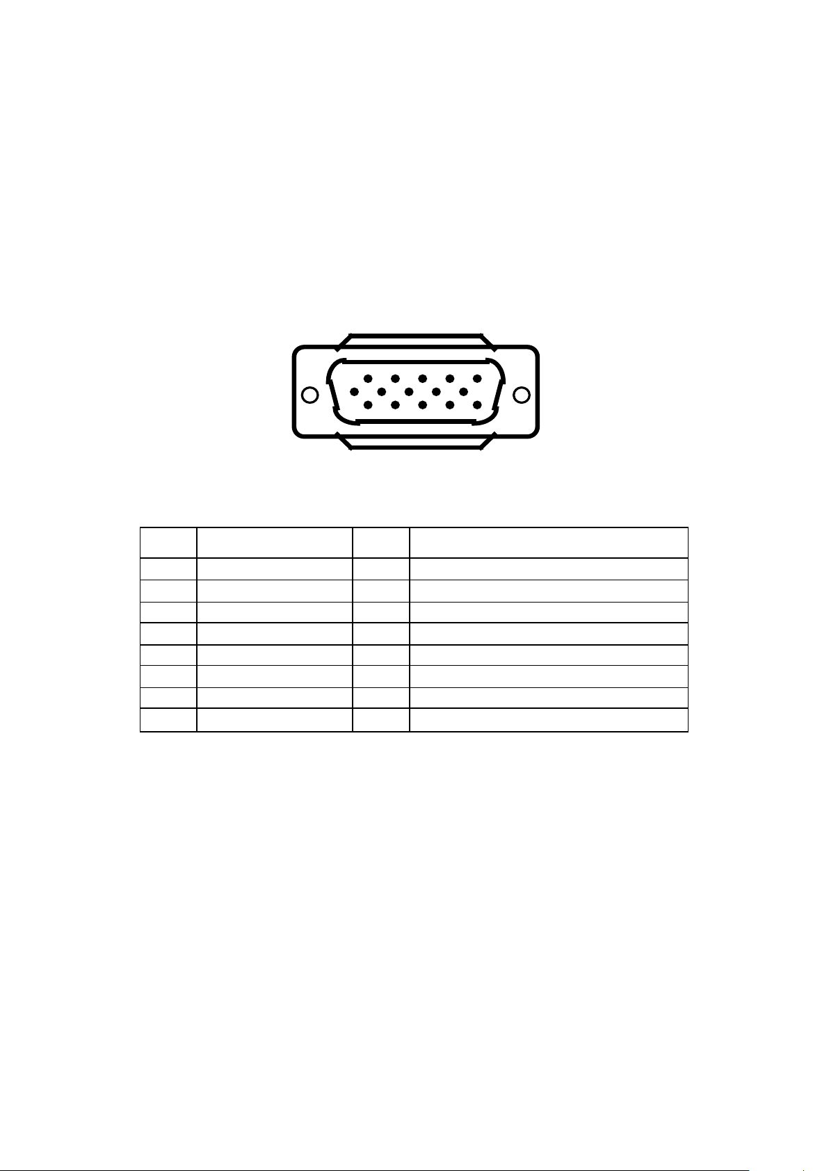
3. D-SUB PIN DISTRIBUTION
3
Blue Video
11
GROUND
5
GROUND
13
Horizontal Sync.
7
Green Video Ground
15
Data Clock (SCL) for PC Bypass
1
6
11
15510
This procedure gives you instructions for installing and using the LCD TV display.
1. Position the disp lay on the desired op eration and plug the po wer cord into a convenient AC outlet.
Three-wire power cord m ust be shielded and is prov ided as a safety precaution as it connects the
chassis and cabinet to the elec trical con duct groun d. If the AC outlet in your location do es not ha ve
provisions for the grounded type plug, the installer should attach the proper adapter to ensure a safe
ground potential.
2. Connect the 15-pin color displa y shielded signal cabl e to your signal system device and lock both
screws on the connector to ensure firm grounding. The connector information is as follow:
15 - Pin Color Display Signal Cable
PIN NO.
DESCRIPTION PIN NO.
DESCRIPTION
1 Red Video 9 Mandatory +5V Suppl y for PC Bypass
2 Green Video 10 Sync. Ground
4 GROUND 12 Bi-directional Data (SDA) for PC Bypass
6 Red Video Ground 14 Vertical Sync.
8 Blue Video Ground
3. S-Video (Y /C): TV rear side : 4 pin Mini-DIN female
SCART: TV rear side : RCA female
TV: TV rear side : IEC type female
AV1: TV rear side : RCA female (Yellow)
Audio: TV rear side : RCA female (Red / White)
PC Input audio: 3.5mm Stereo female
Audio Input for AV1, S-Video, SCART Video : RCA female (Red / White)
Headphone 3.5mm female
Audio line Out (to another speaker) : RCA female (Red / White)
4. Apply power to the display by turning the po wer switch to the "ON" pos it ion and allow about te n sec on ds
for Panel warm-up. The Power-On indicat or lights "GR EEN " when the dis p lay is on.
5. With proper signals feed to the display, a pattern or data should appear on the screen, adjust the
Page 12

11
brightness and contrast to the most pleasing display, or press auto-adjust to get the best picture-quality.
FS*
Full-Screen
AR
Aspect Ratio
6. This TV (with PC f unc tion) has p o wer s a ving f unc tio n f oll o wing the VE SA D PM S. Be sure to connect the
signal cable to the PC.
7. If your TV requires service, it must be returned with the power cord.
3-1 Factory Preset Display Modes:
Analog RGB Signal Timing
MODE ASPECT RATIO HANDLING
STANDARD RESOLUTION
720x400 @ 70Hz 1280 x 768 1024 x 768 N/A
640x480 @ 60Hz 1280 x 768 1024 x 768 N/A
640x480 @ 72Hz 1280 x 768 1024 x 768 N/A
640x480 @ 75Hz 1280 x 768 1024 x 768 N/A
VESA 800x600 @ 60Hz 1280 x 768 1024 x 768 N/A
VESA 800x600 @ 72Hz 1280 x 768 1024 x 768 N/A
VESA 800x600 @ 75Hz 1280 x 768 1024 x 768 N/A
MAC 832x624 @ 75Hz 1280 x 768 1024 x 768 N/A
1:1
MAC 1024x768 @ 75Hz 1280 x 768 1024 x 768 1024 x 768
VESA 1024x768 @ 60Hz 1280 x 768 1024 x 768 1024 x 768
1280x720 @ 60Hz 1280 x 768 1024 x 768 N/A
4. ADJUSTMENT
Page 13
12
4-1 ADJUSTMENT CONTROL FUNCTION
Adjustments items as below:
4-1-1 Power On / Off.
4-1-2 PC
Auto adjustment for Brightness, Contrast, Pixe l Clock Frequenc y, Focus. Picture H / V Posit ion and
Color Temperature.
Recall Cool, Warn and User color adjust for Color Temperature.
4-1-3 PIP
PIP On/Off control, Position Select, Video source select, Audio main/sub Select.
4-1-4 TV
Channel Up / Down, Channel Search, Volume Bass / Treble adjusts.
Blue screen / Language / System / CH swap /Manual scan / CH Del Add
Reset.
4-1-5 Video
Brightness and Contrast adjust, Sharpness. Color and Tint adjust, Reset
4-1-5 Audio
Volume, Bass and Treble adjust, SRS On/Off control, Reset.
4-2 ADJUSTMENT METHOD
Press MENU key to show OSD window or exit, Up / Down key to done the function selection,
And + / - key to done the adjustment.
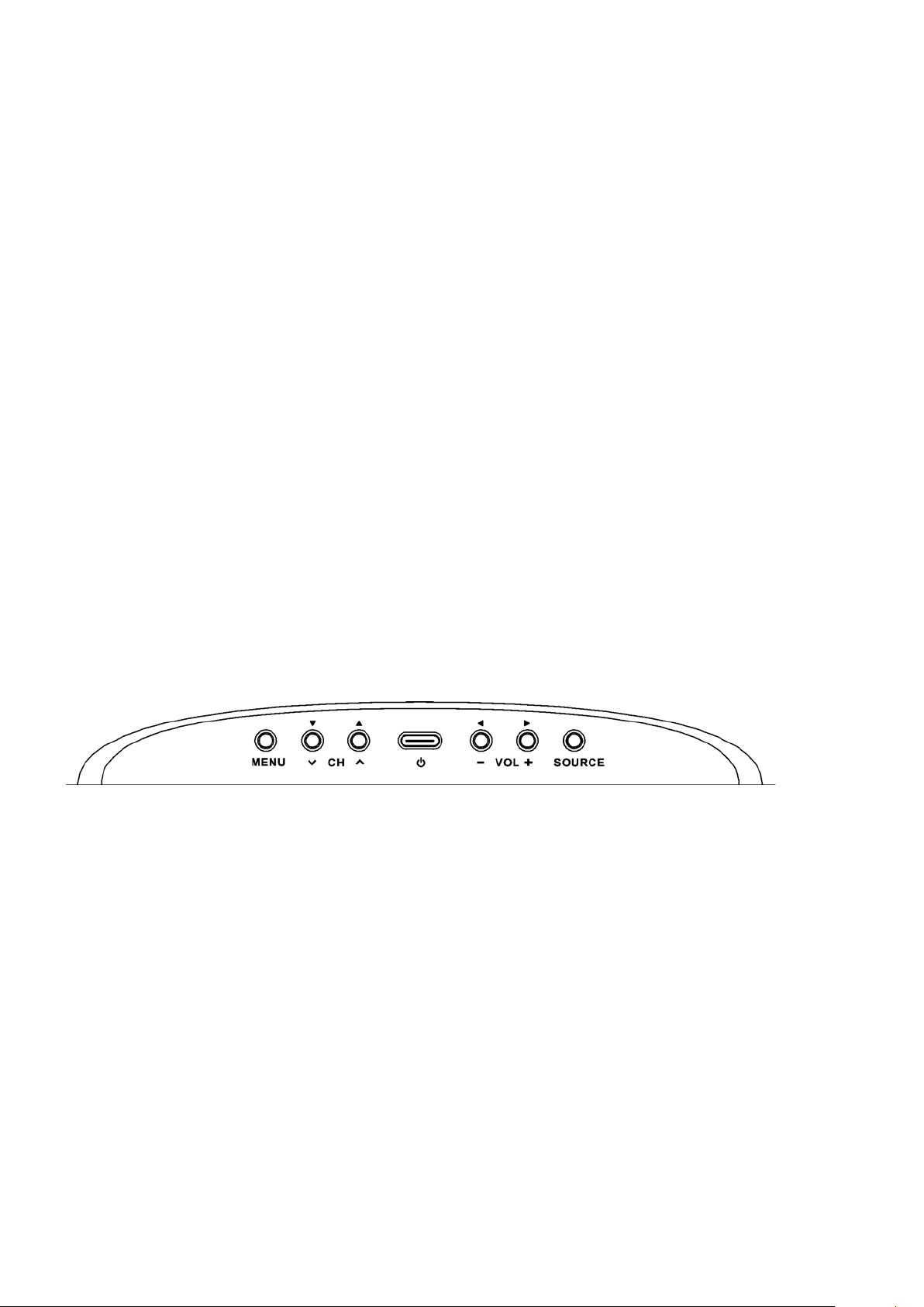
4-3 FRONT P ANEL CONT ROL KNOBS
Power Key: Press to turn on or off the TV.
MENU Key: Press to show the OSD menu and exit OSD menu at the TV.
Down / Up Key: Press to perform select function and channel.
- / + Key: Press to confirm your function selection and adjustment.
Source Key: Press to select your input source.
Page 14
13
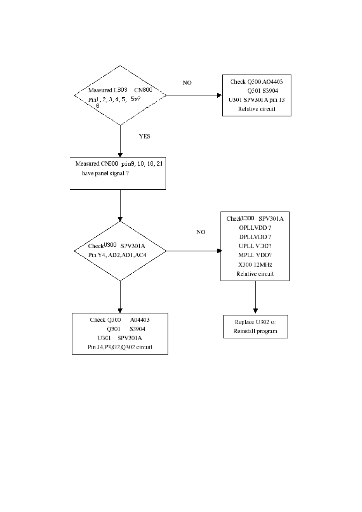
5. TROUBLE SHOOTING CHART
5-1 PANEL CONTROL CIRCUIT
Page 15
14
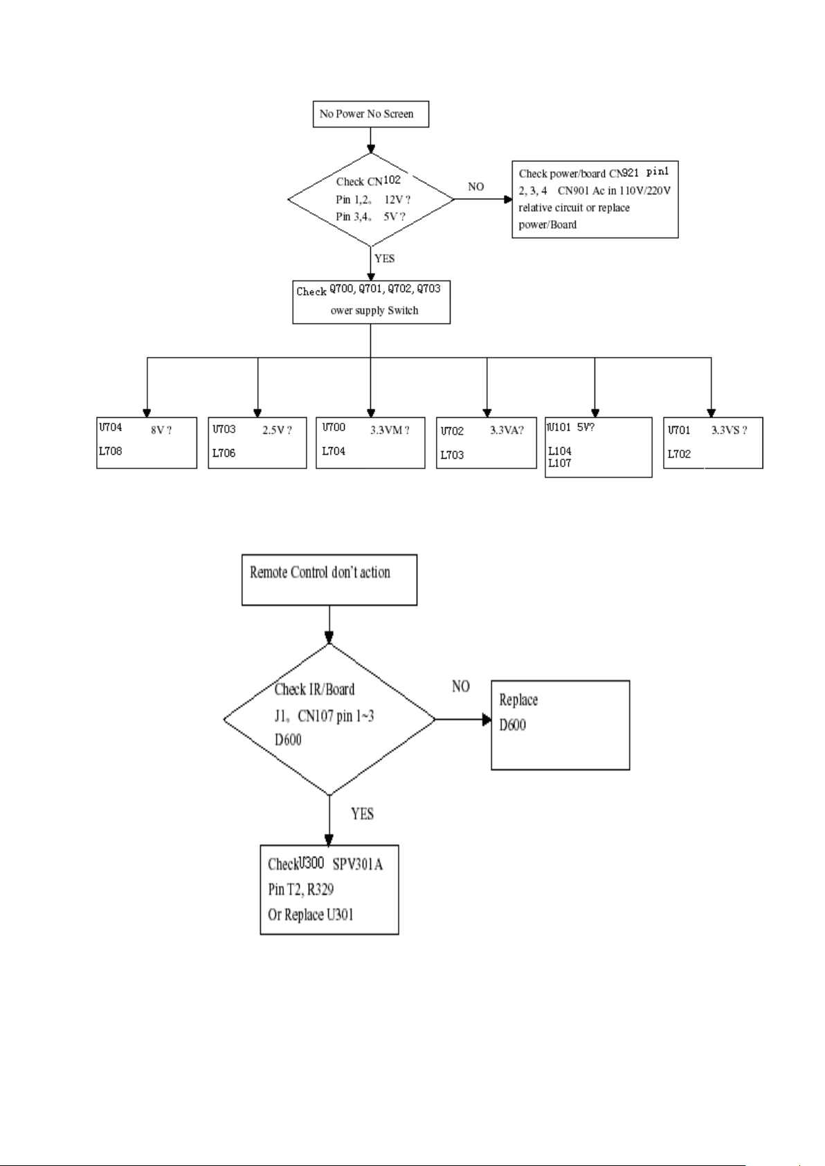
5-2 MAIN BOARD POWER VCC:
5-3 ROMOTE CONTROL BLOCK:
Page 16
15
5-4 KEY BOARD CONTROL BLOCK
5-5 PC CONTROL BLOCK:
Page 17
16
Page 18
17
5-6 AUDIO CONTROL BOCK:
Page 19
18
5-7 VIDEO CONTROL BLOCK:
Note: 1、If Replace “MAIN-BOARD” , Please re-do “DDC-content” programmed & “WHITE-Balance”.
2、If Replace “ POWER-BOARD INVERTER” only, Please re-do “ WHITE-Balance”
Page 20

19
6. White-Balance, Luminance adjustment
PC MODE
TV MODE
Color Temp.
9300
6500
9300
X
0.283
0.313
0.283
Y
0.297
0.329
0.297
Y
350±7
350±7
450±7
Approximately 30 minutes should be allowed for warm up before proceeding white balance adjustment.
Before started adjust white balance, please setting the Chroma-7120 MEM. Channel 1 to 9300 color, MEM.
Channel 2 to 6500 color, and MEM. Channel 3 to 9300 color, (our 9300 parameter is x = 283 ± 15, y = 297 ± 15, Y
= 350 ± 7 cd/m2 ; 6500 parameter is x = 313 ± 15, y = 329 ± 15, Y = 350± 7 cd/m
How to setting MEM. Channel you can reference to Chroma-7120 user guide or simple use “SC” key and “NEXT”
key to modify x, y, Y value and use “ID” key to modify the TEXT description
Following is the procedure to do white-balance adjust
˙Press Number key 1 9 9 9 will into the factory mode, and press Menu key the OSD will show menu and a
word F at Right top of Menu.
˙In the factory mode select MORE function will into Bias and Gain adjustment.
1. ADC Adjustment:
AL Auto level adjust.
RG, GG, BG R, G, B Gain adjust.
RB, GB, BB R, G, B Bias adjust.
2. SCALER Adjustment:
CO, BR Contrast and Brightnes s adjust.
RG, GG, BG R, G, B Gain adjust.
RB, GB, BB R, G, B Bias adjust.
S9, S6, ST , SH Save 9300, 6500, 9300 color temperature.
R9, R6, RT , RH Recall 9300, 6500, 9300 color temperature.
BI Setup Burn-in mode ON / OFF.
ISP Set ISP ON/OFF .
PP Set PIP ON/OFF .
WH Set Wireless Headphone ON/OFF.
SR Set SRS ON/OFF.
CC Set Close Caption ON/OFF.
VC Set V Chip ON/OFF.
EX Exit MORE function to factory mode menu.
II. Bias (Low luminance) adjustment :
1. Press “AUTO” button,
2. Set the contrast on OSD window to the value=51 , color (user )R,G,B set to “50”
3. Adjust the brightness on OSD until chroma 7120 measurement reach the value Y>390 cd/m
III. Gain adjustment :
A. Adjust 9300 color-temperature:
2
)
2
Page 21

20
1. Set the Contrast of OSD function to 45 and Adjust Brightness to chroma-7120 Y>390 cd/m2
2. Switch the chroma-7120 to RGB-mode (with press “MODE” button )
3. Switch the MEM. channel to Channel 01 ( with up or down arrow on chroma-7120 )
4. The LCD-indicator on chroma-7120 will show x = 283 ± 15, y = 297 ± 15, Y = 400 ± 7 cd/m
2
5. Adjust the Color(user)Mode: RED on OSD window, until chroma 7120 indicator reached the
value R=100
6. Adjust the Color (user) Mo de: G R E EN on OSD window, until chroma-7120 i ndica tor r each ed the
value G=100
7. Adjust the Color (user) Mode: BLUE on OSD window, until chroma-7120 indica tor reached the
value B=100
8. Repeat above procedure (Item 5,6,7) until chroma-7120 RGB value meet the tolerance =100±2
9. switch the chroma-7120 to xyY mode With press “MODE” button
10. Press Color (9300) on OSD window to save the adjustment result
B. Adjust 6500 color-temperature:
1. Set the Contrast of OSD function to 45 and Adjust Brightness to chroma-7120 Y>390 cd/m
2
2. Switch the chroma-7120 to RGB-mode (with press “MODE” button )
3. Switch the MEM. Channel to Channel 02 (with up or down arrow on chroma-7120 )
4. The LCD-indicator on chroma-7120 will show x = 313 ± 15, y = 329 ± 15, Y = 400 ± 7 cd/m
2
5. Adjust the Color (user) Mode: RED on OSD window, until chroma 7120 indicator reached the value R=100
6. Adjust the Colo (user) Mode: GREEN on OSD window, until chroma-7120 indicator reached the value G=100
7. Adjust the Color (user) Mode: BLUE on OSD window, until chroma-7120 indicator reached the value B=100
8. Repeat above procedure (item 5, 6, 7) until chroma-7120 RGB value meet the tolerance =100 ± 2
9. Switch the chroma-7120 to xyY mode with press “MODE” button
10. Press Color (6500) on OSD window to save the adjustment result
C. Adjust 9300 color-temperature:
1. Set the Contrast of OSD function to 45 and Adjust Brightness to chroma-7120 Y>440 cd/m
2
2. Switch the chroma-7120 to RGB-mode (with press “MODE” button)
3. Switch the MEM. Channel to Channel 03 (with up or down arrow on chroma-7120)
4. The LCD-indicator on chroma-7120 will show x = 283 ± 15, y = 297 ± 15, Y = 450 ± 7 cd/m
2
5. Adjust the Color (user) Mode: RED on OSD window, until chroma 7120 indicator reached the value R=100
6. Adjust the Color (user) Mode: GREEN on OSD window, until chroma-7120 indicator reached the value
G=100
7. Adjust the Color (user) Mode: BLUE on OSD window, until chroma-7120 indicator reached the value B=100
8. Repeat above procedure (item 5, 6, 7) until chroma-7120 RGB value meet the tolerance =100 ± 2
9. Switch the chroma-7120 to xyY mode with press “MODE” button
10. Press Color (9300) on OSD window to save the adjustment result
Turn the POWER-button off to on to quit from factory mode (in USER-mode, the OSD window location was placed at
middle of screen)
Page 22

21
7. SOFTWARE FLOW CHART
Page 23

22
Page 24

23
Page 25

24
Location
Part No. for TPV
Description
Quan.
Unit
M1V 330 3128
SCREW
4
PCS M1V1730 6128
SCREW
3
PCS ADPF24180A1
ADAPTER ASS'Y
1
PCS CBPFFF5BMSA2T
MAIN BOARD
1
PCS IOPFFA1
I/O BOARD
1
PCS 11T6048 1
CLAMP-S
1
PCS 15T5908 2
BRACKET
1
PCS 15T6096 2 32
MAIN FRAME
1
PCS 15V6161 3
CONNECTOR
1
PCS 26T 800504 6
BARCODE
1
PCS 34T1305AGN 4L
COVER HINGE
1
PCS 34V1306 GM L
COVER CABLE
1
PCS 36V 600 3
Girdding Cloth FOR AUSI
1.02
PCS 40T 270615 6A
ID LABEL
1
PCS 40T 58162435A
LABEL
1
PCS 40T 581902 2A
I/O LABEL
1
PCS 40T 581902 3A
I/O LABEL
1
PCS 41T270161510A
MANUAL
1
PCS 41T780061594A
warranty card
1
PCS 41T780061595A
QSG
1
PCS 44T2701 1
EPS FOR 27"
1
PCS 44T2701 3
EPS
1
PCS 44T2701615 6B
CARTON
1
PCS 44T3231 15
EVA WASHER
1
PCS 44TZ002200 1
PIZZA BOX
1
PCS 45T 76 28 RN
PE BAG FOR MANUAL
1
PCS 45T 88606 3
PE BAG FOR BASE
1
PCS 45T 88609 9
DE BAG
1
PCS 45T 88609 15
EPE COVER FOR BASE
1
PCS 45T 88626 5
PE BAG FOR MOUITOR
1
PCS 50T 500 1
CABLE TIE
2
PCS 52T 1185
MIDDLE TAPE FOR CARTON
70
CM 52T 1186
SMALL TAPE
10
CM 52T 1210 A
ALUMINIUM TAPE
2
PCS 52T 1211 B
ADHESIVE TYPE
6
PCS 85V6085 2
SHIELD
1
PCS 89T404A18N IS
POWER CORD
1
PCS 95T8014 8560
HARNESS
1
PCS 95T8014 10 11
WIRE HARNESS
1
PCS 95T8014 12 13
WIRE HARNESS
1
PCS 95T8018 30636
LVDS
1
PCS 98VR7SW7BEACF
RENITE CIBTROL
1
PCS M1V 140 10120
SCREW M4X10
6
PCS M1V 330 4128
SCREW M3X4
4
PCS M1V 330 4128
SCREW M3X4
4
PCS M1V 330 6128
SCREW
1
PCS M1V 330 6128
SCREW
1
PCS M1V 340 14120
SCREW
4
PCS M1V1140 4128
SCREW 4X6
1
PCS M1V1730 6128
SCREW
4
PCS M1V1730 6128
SCREW
6
PCS
8. PARTS LIST OF CABINET.
EFF5MSNBA2A5TM
Page 26

25
Q1V 330 12120
SCREW 3X12mm
5
PCS Q1V 930 6128
SCREW (T3X6)
2
PCS Q1V1030 12128
SCREW
14
PCS 705LFD4FB34001
27" LCD TV ASS'Y
1
PCS 750VVMH0B11 11
V270B1-L01 VER.C1
1
PCS 34V1378 GN L
BASE-S2
1
PCS
HJPFA60A1
HEADPHONE JACK BOARD
1
PCS
IRPF760A1
LCD TV IR BOARD
1
PCS KEPFA60KA2
KEY BOARD
1
PCS 12T 394 3
RUBBER FOOT
11
PCS 15V6095 2
BUSE DRACKET
1
PCS 33V4658 1 C
LENS POWER
1
PCS 33V4659 1 C
LENS REMOTE
1
PCS 33V4660 AI L
BUTTON FUNCTION
1
PCS 34V1301AGN 3A
BEZEL 27-A2
1
PCS 34V1302AGM 1A
REAR COVER W/O E D
1
PCS 34V1303 GN L
STAND
1
PCS 34V1307 GN L
COVER STAND F
1
PCS
34V1308 GN L
COVER STAND B
1
PCS
95T8014 5 29
HARNESS 5P-5P 600MM
1
PCS M1V 330 8128
SCREW
2
PCS Q1V 130 8120
SCREW
11
PCS Q1V 140 20120
SCREW
4
PCS Q1V 330 8120
SCREW 3X8mm
2
PCS Q1V 330 8120
SCREW 3X8mm
4
PCS Q1V 330 8120
SCREW 3X8mm
2
PCS Q1V1030 8128
SCREW
2
PCS Q1V1030 12128
SCREW
16
PCS
E078L
78T 337 1 L
SPEAKER 4.6OHM 10W
1
PCS
E078R
78T 337 1 R
SPEAKER 4.6OHM 10W
1
PCS
44F3231 20040
EVA
3
PCS
44F3231 20040
EVA
3
PCS 51F 300110 1
WD2102
4 G
51F 300110 1
WD2102
4 G
67F 70339 7T
3.3 UF 50V
2
PCS 67F 70339 7T
3.3 UF 50V
2
PCS
34F6252
319.9*69.9*54.7MM
1
PCS 95F S28152 B
WIRE HARNESS
1
PCS 95F S28152 R
WIRE HARNESS
1
PCS 95F8014 S3 1B
WIRE HARNESS
1
PCS 44F3231 20040
EVA
3
PCS 51F 300110 1
WD2102
4
G
67F 70339 7T
3.3 UF 50V
2
PCS 95F S14 S2 B3
2PIN 650MM 1007#28AWG
1
PCS
34F6252
319.9*69.9*54.7MM
1
PCS 95F S28152 B
WIRE HARNESS
1
PCS 95F S28152 R
WIRE HARNESS
1
PCS 95F8014 S2 1B
WIRE HARNESS
1
PCS
HJPFA60A1
SMTHJPFA60A1
TUNER BOARD SMT
1
PCS 95T 900 53
HARNESS 95MM
1
PCS
CN1
33T3802 5H
WAFER 5P RIGHT ANELE PI
1
PCS
J1
88V 302 7T
PHONE JACK
1
PCS 715V1290 2
HEAD PHONE JACK BOARD
1
PCS
C1
65T0603102 32
CHIP 1000PF 50V X7R
1
PCS
C2
65T0603102 32
CHIP 1000PF 50V X7R
1
PCS
FB1
71T 56U601
BEAD 600 OHM
1
PCS
Page 27

26
FB2
71T 56U601
BEAD 600 OHM
1
PCS
FB3
71T 56U601
BEAD 600 OHM
1
PCS
FB4
71T 56U601
BEAD 600 OHM
1
PCS
IRPF760A1
SMTIRPF760A1
TUNER BOARD SMT
1
PCS 40T 457624 1B
CPU LABEL
1.1
PCS
95T 900 53
HARNESS 95MM
1
PCS
D600
56V 627 3
TSOP4838
1
PCS
D601
81T 12 1 GP
LED
1
PCS
J1
33T3802 4
WAFER PH-4
1
PCS 715V1108 1B
ir led board
1
PCS
C600
65T0603101 31
CHIP 100PF 50V NPO
1
PCS
C601
65T0603104 32
CHIP 0.1UF 50V X7R
1
PCS
C602
65T0603104 32
CHIP 0.1UF 50V X7R
1
PCS
C603
65T0603104 32
CHIP 0.1UF 50V X7R
1
PCS
FB1
71T 59B601 EA
CHIP BEAD 600OHM 0603 T
1
PCS
FB2
71T 59B601 EA
CHIP BEAD 600OHM 0603 T
1
PCS
FB3
71T 59B601 EA
CHIP BEAD 600OHM 0603 T
1
PCS
Q600
57T 417 6
PMBS3906/PHILIPS-SMT
1
PCS
Q601
57T 417 6
PMBS3906/PHILIPS-SMT
1
PCS
R600
61V0603101
CHIPR 100 OHM+-5% 1/10W
1
PCS
R601
61V0603301
CHIP 300 OHM 1/16W
1
PCS
R602
61V0603103
CHIPR 10K OHM+-5% 1/10W
1
PCS
R603
61V0603103
CHIPR 10K OHM+-5% 1/10W
1
PCS
R604
61V0603103
CHIPR 10K OHM+-5% 1/10W
1
PCS
KEPFA60KA2
AIKFA60KA2
KEY BOARD
1
PCS 95T 900 59
WIRE HARNESS
1
PCS
CN6
33T3802 4H
WAFER 4P RIGHT ANGLE
1
PCS
S600
77T 600 1GCJ
TACT SWITCH TSPB-2
1
PCS
S601
77T 600 1GCJ
TACT SWITCH TSPB-2
1
PCS
S602
77T 600 1GCJ
TACT SWITCH TSPB-2
1
PCS
S603
77T 600 1GCJ
TACT SWITCH TSPB-2
1
PCS
S604
77T 600 1GCJ
TACT SWITCH TSPB-2
1
PCS
S605
77T 600 1GCJ
TACT SWITCH TSPB-2
1
PCS
S606
77T 600 1GCJ
TACT SWITCH TSPB-2
1
PCS 715V1169 1
key board for ai
1
PCS
R11
61T 21022252T
2.2K OHM 1% 1/6W
1
PCS
R12
61T 21036252T
3.6K OHM 1% 1/6W
1
PCS
R13
61T 21047252T
4.7K OHM 1% 1/6W
1
PCS
R2
61T 21010252T
MFR 1K OHM +-1% 1/6W
1
PCS
R8
61T 21015252T
1.5K OHM 1/6W 1%
1
PCS
R9
61T 21018252T
MFR 1.8K OHM +-1% 1/6W
1
PCS
ADPF24180A1
AD24180A1SMT
A/D+D/D POWER SMT
1
PCS DCPF1205A3
DC TO DC BOARD
1
PCS 40T 45762420A
S/N LABEL
1
PCS 705L F94 56 01
IC981 ASS'Y
1
PCS 705L F94 57 01
Q901/Q941/D902 ASS'Y
1
PCS 705L F94 57 03
Q942/Q943/D927/D928 ASS
1
PCS 705L F94 87 01
CN901 ASS'Y
1
PCS 705L F94 93 01
BD901 ASS'Y
1
PCS
C901
63T 10722410S
0.22UF 250VAC ARCO
1
PCS
C903
65T306M1022BM
Y1.CAP.001UF 250VAC MUR
1
PCS
C904
65T306M1022BM
Y1.CAP.001UF 250VAC MUR
1
PCS
C905
63T213J105GFA
MPF CAP
1
PCS
C907
67T 40K18116K
105C EC SHAP-IN
1
PCS
Page 28

27
C915
65T306M1022BM
Y1.CAP.001UF 250VAC MUR
1
PCS
C921
65T 1M103 3T6921
0.01uf 20% 1000V Y5V
1
PCS
C922
65V 1K222 2A3000
CERAM1C CAP
1
PCS
C926
64T400K473 57
MPF CAP
1
PCS
C930
67T215L102 6N
KY35VB1000M-L 5*25MM
1
PCS
C932
67T215L1024NL
KY25VB1000M-L 10*25MM
1
PCS
C933
67T215L1024NL
KY25VB1000M-L 10*25MM
1
PCS
C934
67T 2152214NT GP
KY25VB220M-TP5 8*11.5
1
PCS
C942
65V 1K222 2A3000
CERAM1C CAP
1
PCS
C948
67T215L102 6N
KY35VB1000M-L 5*25MM
1
PCS
C949
67T215L102 6N
KY35VB1000M-L 5*25MM
1
PCS
C950
67T215L102 6N
KY35VB1000M-L 5*25MM
1
PCS
C951
67T215L102 6N
KY35VB1000M-L 5*25MM
1
PCS
C955
67T215L471 6N
KY35VB470M-L 10*20MM
1
PCS
CN921
95T8013 10 18
WIRE HARNESS
1
PCS
CN951
33T3802 10
PLUG
1
PCS
CN952
33T3802 12
WAFER PH-12
1
PCS
D920
93T1100 1052T
DIODE
1
PCS
D921
93T1100 1052T
DIODE
1
PCS
D922
93V1020 752T
UF4003 DO-41
1
PCS
D941
93T1100 1052T
DIODE
1
PCS
D942
93T1100 1052T
DIODE
1
PCS
D943
93V1020 752T
UF4003 DO-41
1
PCS
IC922
56V 139 3A
PC123Y22
1
PCS
IC924
56V 139 3A
PC123Y22
1
PCS
IC925
56V 139 3A
PC123Y22
1
PCS
IC942
56V 139 3A
PC123Y22
1
PCS
L901
73L 253156 LG
CHOKE COIL
1
PCS
L902
73L 253156 LG
CHOKE COIL
1
PCS
L903
73L 174 48 LG
LINE FILTER
1
PCS
L904
73L 174 49 LG
LINE FILTER
1
PCS
L905
73L 174 52LSG
CHOKE COIL
1
PCS
L906
73L 174 44 TG
CHOKE COIL
1
PCS
L923
73T 253155 L
CHOKE
1
PCS
L952
73L 174 47LSG
LINE FILTER
1
PCS
L953
73L 174 46LSG
FILTER
1
PCS
R905
61T153M27858G6267
0.27 OHM 5% 3W
1
PCS
R919
61T153M27858G6267
0.27 OHM 5% 3W
1
PCS
R921
61T152M10458G6267
100K OHM 5% 2W
1
PCS
R945
61T153M47358G6267
47K OHM 5% 3W
1
PCS
R950
61T 20K398GB1
CEMENTR 0.39 OHM +-10%
1
PCS
RJ905
95T 90 26
WIRE HARNESS
1
PCS
T921
80LL26T 1 TG
X'FMR
1
PCS
T951
80LL26T 2 TG
X'FMR
1
PCS AD24180A1AI
A/D+D/D POWER AUTO INS.
1
PCS
C910
65T0805104 32
CHIP 0.1U 50V X7R
1
PCS
C911
65T0805102 32
CHIP 1000P 50VX7R 0805
1
PCS
C912
65T0805474 22
CHIP 0.47UF 25V X7R
1
PCS
C913
65T0805103 32
10NF/50V/0805/X7R
1
PCS
C914
65T0805104 32
CHIP 0.1U 50V X7R
1
PCS
C920
65T0805104 32
CHIP 0.1U 50V X7R
1
PCS
C924
65T0805104 32
CHIP 0.1U 50V X7R
1
PCS
C927
65T0805102 32
CHIP 1000P 50VX7R 0805
1
PCS
C935
65T0805104 32
CHIP 0.1U 50V X7R
1
PCS
C937
65T0805104 32
CHIP 0.1U 50V X7R
1
PCS
C938
65T0805104 32
CHIP 0.1U 50V X7R
1
PCS
C939
65T0805104 32
CHIP 0.1U 50V X7R
1
PCS
Page 29

28
C946
65T0805471 31
CHIP 470PF 50V NPO
1
PCS
C953
65T0805104 32
CHIP 0.1U 50V X7R
1
PCS
C956
65T0805104 32
CHIP 0.1U 50V X7R
1
PCS
C958
65T0805471 31
CHIP 470PF 50V NPO
1
PCS
C959
65T0805334 22
0.33UF+-10% 25V X7R 080
1
PCS
C964
65T1206103B2M
CHIP 0.01UF 630V X7R
1
PCS
C965
65T0805104 32
CHIP 0.1U 50V X7R
1
PCS
D901
93T3060 10
3A 600V
1
PCS
D904
93T 6432P
LL4148 BY PANJIT
1
PCS
D905
93T 6432P
LL4148 BY PANJIT
1
PCS
D906
93T 6432P
LL4148 BY PANJIT
1
PCS
D907
93T 6432P
LL4148 BY PANJIT
1
PCS
D923
93T 6432P
LL4148 BY PANJIT
1
PCS
D924
93T 6432P
LL4148 BY PANJIT
1
PCS
D926
93T 6432P
LL4148 BY PANJIT
1
PCS
D929
93T 6432P
LL4148 BY PANJIT
1
PCS
D944
93T 6432P
LL4148 BY PANJIT
1
PCS
D945
93T 6432P
LL4148 BY PANJIT
1
PCS
D946
93T 6432P
LL4148 BY PANJIT
1
PCS
D947
93T 6432P
LL4148 BY PANJIT
1
PCS
D949
93T 6432P
LL4148 BY PANJIT
1
PCS
D950
93T 6432P
LL4148 BY PANJIT
1
PCS
IC901
56V 538 8
TDA4863-2G SO-8
1
PCS
IC941
56V 379 38
L6565D SO-8
1
PCS
Q922
57T 417 4
CHIP PMBS3904 B Y PHI LI P
1
PCS
Q924
57T 760 5
DTC144WKA BY FOHM SMT
1
PCS
R901
61V1206684
CHIP 680K OHM 1/8W
1
PCS
R902
61V1206684
CHIP 680K OHM 1/8W
1
PCS
R903
61V0805683
CHIPR 68K OHM+-5% 1/8W
1
PCS
R904
61V0805470
CHIP 47 OHM 1/10W
1
PCS
R906
61V1206624
CHIP 620K 5% 1/4W
1
PCS
R907
61V1206624
CHIP 620K 5% 1/4W
1
PCS
R908
61V1206000
CHIP 0 OHM 1/8W
1
PCS
R909
61V0805103
CHIP 10K OHM 1/10W
1
PCS
R910
61V0805103
CHIP 10K OHM 1/10W
1
PCS
R911
61V1206330 3F
330K OHM 1/4W 1%
1
PCS
R912
61V1206330 3F
330K OHM 1/4W 1%
1
PCS
R913
61V1206330 3F
330K OHM 1/4W 1%
1
PCS
R914
61V0805191 2F
19.1K OHM 1/8W 1%
1
PCS
R915
61V1206472
CHIP 4.7KOHM 5% 1/4W
1
PCS
R916
61V1206332
CHIP 3.3KOHM 1/8W 5%
1
PCS
R917
61V1206332
CHIP 3.3KOHM 1/8W 5%
1
PCS
R920
61V0805100 2F
CHIP 10K OHM 1/8W 1%
1
PCS
R922
61V0805000
CHIP 0OHM 1/10W
1
PCS
R923
61V1206100 4F
1M OHM 1/4W 1%
1
PCS
R924
61V1206100 4F
1M OHM 1/4W 1%
1
PCS
R925
61V0805689
CHIP 6.8OHM 5% 1/8W
1
PCS
R926
61V1206205
CHIP 2M OHM 5% 1/4W
1
PCS
R927
61V1206205
CHIP 2M OHM 5% 1/4W
1
PCS
R928
61V1206562
CHIP 5.6K OHM 1/4W
1
PCS
R929
61V1206330
CHIP 33 OHM 5% 1/4W
1
PCS
R931
61V0805102
CHIPR 1K OHM +-5% 1/8W
1
PCS
R932
61V0805393
SMD 39KOHM/0805/+-5% 1/
1
PCS
R933
61V0805471
CHIPR 470 OHM+-5% 1/8W
1
PCS
R934
61V0805102
CHIPR 1K OHM +-5% 1/8W
1
PCS
R935
61V0805472
CHIRP 4.7K OHM +-5% 1/8
1
PCS
R936
61V0805220
CHIP 22 OHM 5% 0805 1/8
1
PCS
Page 30

29
R940
61V0805100 2F
CHIP 10K OHM 1/8W 1%
1
PCS
R944
61V0805000
CHIP 0OHM 1/10W
1
PCS
R946
61V1206330
CHIP 33 OHM 5% 1/4W
1
PCS
R947
61V0805000
CHIP 0OHM 1/10W
1
PCS
R948
61V0805330
CHIP 33 OHM 5% 1/10W
1
PCS
R949
61V0805273
CHIP 27KOHM 5% 0805 1/8
1
PCS
R951
61V0805242
CHIP 2.4KOHM 1% 1/8W
1
PCS
R952
61V0805682
CHIP 6.8KOHM 5% 0805 1/
1
PCS
R953
61V0805563
CHIP 56K OHM 1/8W
1
PCS
R954
61V0805100
CHIP 10OHM 1/10W
1
PCS
R955
61V0805100
CHIP 10OHM 1/10W
1
PCS
R957
61V0805200 9F
CHIP 20 OHM 1/10W 1%
1
PCS
R958
61V0805202
CHIP 2KOHM 1/8W
1
PCS
R959
61V0805115 2F
CHIP 11.5K OHM 1/10W 1%
1
PCS
R960
61V0805133
CHIPR 13KOHM +-5% 1/8W
1
PCS
R961
61V0805152
CHIPR 1.5K OHM +-5% 1/8
1
PCS
R962
61V1206102
CHIP 1K OHM 5% 1/4W
1
PCS
R964
61V0805104
CHIPR 100K OHM+-5% 1/8W
1
PCS
R965
61V0805103
CHIP 10K OHM 1/10W
1
PCS
R967
61V0805222
CHIP 2.2KOHM 5% 0805 1/
1
PCS
R968
61V1206101
CHIP 100 OHM 5% 1/4W
1
PCS
R973
61V1206470
CHIP 47OHM 5% 1/4W
1
PCS
R974
61V1206330
CHIP 33 OHM 5% 1/4W
1
PCS
R983
61V1206100 3F
CHIP 100K OHM +-1% 1/4W
1
PCS
RJ901
61V1206000
CHIP 0 OHM 1/8W
1
PCS
RJ903
61V1206000
CHIP 0 OHM 1/8W
1
PCS
RJ904
61V1206000
CHIP 0 OHM 1/8W
1
PCS
ZD921
93T 39S 10 T
RLZ6.8B LLDS
1
PCS
ZD942
93T 39S 33 T
PTZ 13B
1
PCS
ZD943
93T 39S 24 T
RLZ 5.6B LLDS
1
PCS
ZD944
93T 39S 15 T
RLZ15B
1
PCS
ZD946
93T 39S 42 T
RLZ27B LLDS
1
PCS 715T1180 3
PCB
1
PCS
C908
65T517M103 3T
0.01UF 20% 500V Y5P
1
PCS
C909
67T 2151007NT
10UF 50V NCC 5*11MM
1
PCS
C923
67T 2151007NT
10UF 50V NCC 5*11MM
1
PCS
C925
67T 2154707NT
47UF 50V NCC 5*11MM
1
PCS
C941
65T 1M103 3T6921
0.01uf 20% 1000V Y5V
1
PCS
C944
67T 2154707NT
47UF 50V NCC 5*11MM
1
PCS
C945
67T 2154707NT
47UF 50V NCC 5*11MM
1
PCS
C957
67T 2151007NT
10UF 50V NCC 5*11MM
1
PCS
CN901
6V 31500
EYELET
2
PCS
F901
84V 55 4
FUSE
1
PCS
IC923
56V 158 10 T
AZ431AZ-A TO-92
1
PCS
IC943
56V 158 10 T
AZ431AZ-A TO-92
1
PCS
L904
6V 31502
1.5MM RIVET
4
PCS
L906
6V 31502
1.5MM RIVET
4
PCS
L921
71T 55 23 S
FERRITE BEAD K-TYPE
1
PCS
L951
71T 55 23 S
FERRITE BEAD K-TYPE
1
PCS
NR901
6V 31502
1.5MM RIVET
2
PCS
NR902
6V 31502
1.5MM RIVET
2
PCS
Q926
57T 566 1
2N5060RLRAG
1
PCS
Q945
57T 419501 T
KTC945P
1
PCS
Q946
57T 420501 T
KTA733P
1
PCS
Q947
57T 419501 T
KTC945P
1
PCS
Q948
57T 420501 T
KTA733P
1
PCS
R937
61T 60168152T
680 OHM +-2% 1/6W
1
PCS
Page 31

30
R966
61T 60110252T
1K OHM +-2% 1/6W
1
PCS
T921
6V 31502
1.5MM RIVET
4
PCS
T951
6V 31502
1.5MM RIVET
4
PCS DC1205A3SMT
DC TO DC BOARD FOR SMT
1
PCS
C801
67T215V221 4K
EC 220F 25V
1
PCS
C806
67T215L471 2K
LOW ESR 470UF 10V
1
PCS
C807
67T215L471 2K
LOW ESR 470UF 10V
1
PCS
CN801
33T800913Z H
PIN HEADER 1*13 R/A
1
PCS 715V1278 3
PCB
1
PCS
C802
65T0805105 22
CHIP 1UF 25V X7R 0805
1
PCS
C803
65T0603102 32
CHIP 1000PF 50V X7R
1
PCS
C804
65T0603102 32
CHIP 1000PF 50V X7R
1
PCS
C805
65T0603471 31
CHIP 470PF 50V NPO
1
PCS
C808
65T0805102 32
CHIP 1000P 50VX7R 0805
1
PCS
C809
65T0603104 32
CHIP 0.1UF 50V X7R
1
PCS
C810
65T0805102 32
CHIP 1000P 50VX7R 0805
1
PCS
D801
93T8004 2
8A 40V
1
PCS
IC801
56T 133 32 NS
LM3485
1
PCS
L801
73T M5822020T
22UH +-20%
1
PCS
Q801
57T 763 3
AO4411L SO-8 BY AOS SMT
1
PCS
R801
61V0603360 2F
chip 36k ohm 1/10w 1%
1
PCS
R802
61V0603620 2F
CHIP 62K OHM 1/16W 1%
1
PCS
R803
61V0603200 2F
CHIP 20K OHM 1/16W 1%
1
PCS
R804
61V1206220
CHIP 22OHM 5% 1/8W
1
PCS 90V 427 1
HEAT SINK
1
PCS M1V1730 8128
SCREW M3x8
1
PCS
IC981
56V 379 40
TOP246Y TO220-7C
1
PCS 12T 372 5
MICA
1
PCS 90V 426 1
HEAT SINK
1
PCS M1V1730 12128
SCREW
3
PCS
D902
93T 220 23
FMX-G26S
1
PCS
Q901
57T 667 19
2SK3523-01R
1
PCS
Q941
57T 667 21
STP10NK70ZFP
1
PCS 5T 42 1
CUSHION
2
PCS 12T 372 1
MICA
2
PCS 90V 428 1
HEAT SINK
1
PCS M1V1730 10128
SCREW M3x10
4
PCS
D927
93T 60247
FME-220A
1
PCS
D928
93T 60247
FME-220A
1
PCS
Q942
57V 600 45
IRF3415 TO-220AB
1
PCS
Q943
57V 600 45
IRF3415 TO-220AB
1
PCS 95T 900 42
WIRE HARNESS
1
PCS
96T 29 4
SHRINK TUBE UL/CSA
3
PCS
CN901
87T 501 19 RF
AC INLET RIGHT ANGLE
1
PCS 90V 425 1
HEAT SINK
1
PCS M1V1730 10128
SCREW M3x10
1
PCS
BD901
93T 50460 18
D10XB60
1
PCS
CBPFFF5BMSA2T
SMTFFD4BMSACT
27" LCD TV MAIN AUTO IN
1
PCS 40T 457624 1B
CPU LABEL
1
PCS 40T 45762412B
CBPC LABEL
1
PCS 44T3231508512
CHIELD D-SUB
1
PCS M1T 330 8128
SCREW M3X8
1
PCS
C602
67T305V331 3
330UF +-20% 16V
1
PCS
CN1
33V801712F
PIN HEADER 2*6P 2.0MM
1
PCS
CN101
33V801736A H
PIN HEADER DUAL ROW 36P
1
PCS
CN102
33T3278 10
10 PLUG B10E-XHA/JST E1
1
PCS
Page 32

31
CN105
33T802412D
HEADER FEMALE 12P 2.0MM
1
PCS
CN106
33T802412D
HEADER FEMALE 12P 2.0MM
1
PCS
CN107
33T3802 8H
WAFER 8P RIGHT ANGLE PI
1
PCS
CN111
33T3802 3H
WAFER 3P RIGHT ANGLE
1
PCS
CN112
33T3802 2H
WAFER 2P RIGHT ANGLE
1
PCS
CN2
33V801712F
PIN HEADER 2*6P 2.0MM
1
PCS
CN501
88T 35315F HA
D-SU13 15PIN
1
PCS
CN600
33T3802 5H
WAFER 5P RIGHT ANELE PI
1
PCS
CN601
88T 30214K
PHONE JACK
1
PCS
CN800
33T801724A H
PIN HEADER 2.0MM 2026P2
1
PCS
L602
73T 253158 L
CHOKE COIL
1
PCS
L603
73T 253158 L
CHOKE COIL
1
PCS
L607
73T 253158 L
CHOKE COIL
1
PCS
L608
73T 253158 L
CHOKE COIL
1
PCS
L701
73V 253137 ER
CHOKE COIL
1
PCS
L707
73V 253137 ER
CHOKE COIL
1
PCS
MTGU602
90T 365601
HEAT SINK-L
1
PCS
MTGU602
90V6214 1
HEAT SINK-S
1
PCS
R723
61T152M829 64
8.2 OHM +-5% 2W
1
PCS
R724
61T152M829 64
8.2 OHM +-5% 2W
1
PCS
U310
56T1133 52AO3
TTE-SKD-CM27
1
PCS
X1
93T 2251B
12MHZ/20PF/49US
1
PCS
X200
93T 2265B J
20.250 AE13F-BK4
1
PCS
X300
93T 2251B J
NXS12.000AC30F-BT-2
1
PCS
X301
93T 22 61 J
CRYSTAL 32.768 KHZ 3*9
1
PCS 715V1265 J
MAIN BOARD PCB
1
PCS
C1
67T 312470 3
SMD EC 47UF 16V 85C D
1
PCS
C10
65T0603104 12
CHIP 0.1UF 50V X7R
1
PCS
C11
65T0603104 12
CHIP 0.1UF 50V X7R
1
PCS
C115
65T0603471 31
CHIP 470PF 50V NPO
1
PCS
C116
65T0603471 31
CHIP 470PF 50V NPO
1
PCS
C117
65T0603471 31
CHIP 470PF 50V NPO
1
PCS
C118
65T0603471 31
CHIP 470PF 50V NPO
1
PCS
C12
65T0603104 12
CHIP 0.1UF 50V X7R
1
PCS
C13
67T 312100 3
SMD EC 10UF 16V 85C B
1
PCS
C135
65T0603101 31
CHIP 100PF 50V NPO
1
PCS
C136
65T0603104 12
CHIP 0.1UF 50V X7R
1
PCS
C137
65T0603102 31
CHIP 1000PF 50V NPO
1
PCS
C138
65T0603104 12
CHIP 0.1UF 50V X7R
1
PCS
C14
67T 312100 3
SMD EC 10UF 16V 85C B
1
PCS
C143
65T0603104 12
CHIP 0.1UF 50V X7R
1
PCS
C144
65T0603104 12
CHIP 0.1UF 50V X7R
1
PCS
C145
65T0603104 12
CHIP 0.1UF 50V X7R
1
PCS
C15
65T0603104 12
CHIP 0.1UF 50V X7R
1
PCS
C16
67T 312100 3
SMD EC 10UF 16V 85C B
1
PCS
C17
65T0603104 12
CHIP 0.1UF 50V X7R
1
PCS
C18
67T 312470 3
SMD EC 47UF 16V 85C D
1
PCS
C2
65T0603104 12
CHIP 0.1UF 50V X7R
1
PCS
C20
65T0603330 31
CHIP 33PF 50V NPO
1
PCS
C200
65T0603152 32
CHIP 1500PF 50V X7R
1
PCS
C201
65T0603100 31
CHIP 10PF 50V NPO
1
PCS
C202
65T0603100 31
CHIP 10PF 50V NPO
1
PCS
C203
65T0603102 32
CHIP 1000PF 50V X7R
1
PCS
C204
67T 312479 3
SMD EC 4.7UF 16V 85C
1
PCS
C205
65T0805684 17
CHIP 0.68UF 16V Y5V
1
PCS
C206
65T0805684 17
CHIP 0.68UF 16V Y5V
1
PCS
C207
65T0603473 32
CHIP 0.047UF 50V X7R
1
PCS
Page 33

32
C208
65T0805684 17
CHIP 0.68UF 16V Y5V
1
PCS
C209
65T0603470 31
CHIP 47PF 50V NPO
1
PCS
C21
65T0603330 31
CHIP 33PF 50V NPO
1
PCS
C210
65T0603470 31
CHIP 47PF 50V NPO
1
PCS
C211
65T0603470 31
CHIP 47PF 50V NPO
1
PCS
C212
67T 312479 3
SMD EC 4.7UF 16V 85C
1
PCS
C213
65T0603220 31
CHIP 22PF 50V NPO
1
PCS
C214
65T0603473 32
CHIP 0.047UF 50V X7R
1
PCS
C215
65T0805473 32
CHIP 0.04IF 50V X7R
1
PCS
C216
65T0603224 17
CHIP 0.22UF 16V Y5V
1
PCS
C217
65T0603224 17
CHIP 0.22UF 16V Y5V
1
PCS
C218
65T0603224 17
CHIP 0.22UF 16V Y5V
1
PCS
C22
65T0603330 31
CHIP 33PF 50V NPO
1
PCS
C223
65T0603683 32
CHIP 0.068UF 50V X7R
1
PCS
C227
65T0603152 32
CHIP 1500PF 50V X7R
1
PCS
C228
65T0603391 31
CHIP 390PF 50V NPO
1
PCS
C229
65T0603224 17
CHIP 0.22UF 16V Y5V
1
PCS
C23
65T0603221 31
CHIP 220PF 50V NPO
1
PCS
C230
67T 312101 3
SMD EC 100UF 16V 85C D
1
PCS
C231
67T 312100 3
SMD EC 10UF 16V 85C B
1
PCS
C232
65T0603104 12
CHIP 0.1UF 50V X7R
1
PCS
C233
65T0603104 12
CHIP 0.1UF 50V X7R
1
PCS
C234
65T0603104 12
CHIP 0.1UF 50V X7R
1
PCS
C235
65T0603104 12
CHIP 0.1UF 50V X7R
1
PCS
C236
65T0603104 12
CHIP 0.1UF 50V X7R
1
PCS
C237
65T0603104 12
CHIP 0.1UF 50V X7R
1
PCS
C238
65T0603104 12
CHIP 0.1UF 50V X7R
1
PCS
C239
65T0603104 12
CHIP 0.1UF 50V X7R
1
PCS
C240
65T0603104 12
CHIP 0.1UF 50V X7R
1
PCS
C241
65T0603470 31
CHIP 47PF 50V NPO
1
PCS
C243
65T0603104 12
CHIP 0.1UF 50V X7R
1
PCS
C3
65T0603104 12
CHIP 0.1UF 50V X7R
1
PCS
C300
65T0603104 12
CHIP 0.1UF 50V X7R
1
PCS
C301
65T0603104 12
CHIP 0.1UF 50V X7R
1
PCS
C302
65T0603104 12
CHIP 0.1UF 50V X7R
1
PCS
C303
65T0603104 12
CHIP 0.1UF 50V X7R
1
PCS
C304
65T0603104 12
CHIP 0.1UF 50V X7R
1
PCS
C305
65T0603104 12
CHIP 0.1UF 50V X7R
1
PCS
C306
65T0603104 12
CHIP 0.1UF 50V X7R
1
PCS
C307
65T0603104 12
CHIP 0.1UF 50V X7R
1
PCS
C308
65T0603104 12
CHIP 0.1UF 50V X7R
1
PCS
C309
65T0603104 12
CHIP 0.1UF 50V X7R
1
PCS
C310
65T0603104 12
CHIP 0.1UF 50V X7R
1
PCS
C311
65T0603104 12
CHIP 0.1UF 50V X7R
1
PCS
C312
65T0603104 12
CHIP 0.1UF 50V X7R
1
PCS
C313
65T0603104 12
CHIP 0.1UF 50V X7R
1
PCS
C314
65T0603104 12
CHIP 0.1UF 50V X7R
1
PCS
C315
65T0603104 12
CHIP 0.1UF 50V X7R
1
PCS
C316
65T0603104 12
CHIP 0.1UF 50V X7R
1
PCS
C317
65T0603104 12
CHIP 0.1UF 50V X7R
1
PCS
C318
65T0603104 12
CHIP 0.1UF 50V X7R
1
PCS
C319
65T0603104 12
CHIP 0.1UF 50V X7R
1
PCS
C320
65T0603104 12
CHIP 0.1UF 50V X7R
1
PCS
C321
65T0603104 12
CHIP 0.1UF 50V X7R
1
PCS
C322
65T0603104 12
CHIP 0.1UF 50V X7R
1
PCS
C323
65T0603104 12
CHIP 0.1UF 50V X7R
1
PCS
C324
67T 312100 3
SMD EC 10UF 16V 85C B
1
PCS
Page 34

33
C325
67T 312100 3
SMD EC 10UF 16V 85C B
1
PCS
C326
65T0603104 12
CHIP 0.1UF 50V X7R
1
PCS
C327
65T0603104 12
CHIP 0.1UF 50V X7R
1
PCS
C328
65T0603104 12
CHIP 0.1UF 50V X7R
1
PCS
C329
65T0603104 12
CHIP 0.1UF 50V X7R
1
PCS
C330
67T 312100 3
SMD EC 10UF 16V 85C B
1
PCS
C331
67T 312100 3
SMD EC 10UF 16V 85C B
1
PCS
C332
65T0603104 12
CHIP 0.1UF 50V X7R
1
PCS
C333
65T0603104 12
CHIP 0.1UF 50V X7R
1
PCS
C334
65T0603104 12
CHIP 0.1UF 50V X7R
1
PCS
C335
65T0603104 12
CHIP 0.1UF 50V X7R
1
PCS
C336
65T0603104 12
CHIP 0.1UF 50V X7R
1
PCS
C337
65T0603104 12
CHIP 0.1UF 50V X7R
1
PCS
C338
65T0603104 12
CHIP 0.1UF 50V X7R
1
PCS
C339
65T0603104 12
CHIP 0.1UF 50V X7R
1
PCS
C340
65T0603104 12
CHIP 0.1UF 50V X7R
1
PCS
C341
65T0603104 12
CHIP 0.1UF 50V X7R
1
PCS
C342
65T0603104 12
CHIP 0.1UF 50V X7R
1
PCS
C343
65T0603104 12
CHIP 0.1UF 50V X7R
1
PCS
C344
65T0603104 12
CHIP 0.1UF 50V X7R
1
PCS
C345
65T0603104 12
CHIP 0.1UF 50V X7R
1
PCS
C346
65T0603104 12
CHIP 0.1UF 50V X7R
1
PCS
C347
67T 312100 3
SMD EC 10UF 16V 85C B
1
PCS
C348
67T 312100 3
SMD EC 10UF 16V 85C B
1
PCS
C349
65T0603104 12
CHIP 0.1UF 50V X7R
1
PCS
C350
65T0603104 12
CHIP 0.1UF 50V X7R
1
PCS
C351
65T0603104 12
CHIP 0.1UF 50V X7R
1
PCS
C352
65T0603104 12
CHIP 0.1UF 50V X7R
1
PCS
C353
67T 312100 3
SMD EC 10UF 16V 85C B
1
PCS
C354
67T 312100 3
SMD EC 10UF 16V 85C B
1
PCS
C355
65T0603104 12
CHIP 0.1UF 50V X7R
1
PCS
C356
65T0603104 12
CHIP 0.1UF 50V X7R
1
PCS
C357
65T0603104 12
CHIP 0.1UF 50V X7R
1
PCS
C358
65T0603104 12
CHIP 0.1UF 50V X7R
1
PCS
C360
65T0603104 12
CHIP 0.1UF 50V X7R
1
PCS
C361
65T0603104 12
CHIP 0.1UF 50V X7R
1
PCS
C362
65T0603104 12
CHIP 0.1UF 50V X7R
1
PCS
C364
67T 312100 3
SMD EC 10UF 16V 85C B
1
PCS
C366
67T 312101 3
SMD EC 100UF 16V 85C D
1
PCS
C367
65T0603150 31
CHIP 15PF 50V NPO
1
PCS
C368
65T0603150 31
CHIP 15PF 50V NPO
1
PCS
C369
65T0603150 31
CHIP 15PF 50V NPO
1
PCS
C370
65T0603150 31
CHIP 15PF 50V NPO
1
PCS
C371
67T 312109 3
SMD EC 1UF 16V 85C
1
PCS
C372
65T0603104 12
CHIP 0.1UF 50V X7R
1
PCS
C373
65T0603104 12
CHIP 0.1UF 50V X7R
1
PCS
C374
65T0603104 12
CHIP 0.1UF 50V X7R
1
PCS
C375
65T0603104 12
CHIP 0.1UF 50V X7R
1
PCS
C376
65T0603104 12
CHIP 0.1UF 50V X7R
1
PCS
C377
65T0603104 12
CHIP 0.1UF 50V X7R
1
PCS
C378
65T0603104 12
CHIP 0.1UF 50V X7R
1
PCS
C380
65T0603104 12
CHIP 0.1UF 50V X7R
1
PCS
C381
65T0603104 12
CHIP 0.1UF 50V X7R
1
PCS
C382
65T0603104 12
CHIP 0.1UF 50V X7R
1
PCS
C383
65T0603104 12
CHIP 0.1UF 50V X7R
1
PCS
C384
65T0603104 12
CHIP 0.1UF 50V X7R
1
PCS
C385
65T0603104 12
CHIP 0.1UF 50V X7R
1
PCS
Page 35

34
C386
65T0603104 12
CHIP 0.1UF 50V X7R
1
PCS
C387
65T0603220 31
CHIP 22PF 50V NPO
1
PCS
C388
65T0603220 31
CHIP 22PF 50V NPO
1
PCS
C389
65T0603220 31
CHIP 22PF 50V NPO
1
PCS
C390
65T0603220 31
CHIP 22PF 50V NPO
1
PCS
C391
65T0603270 31
CHIP 27PF 50V NPO
1
PCS
C394
65T0603104 12
CHIP 0.1UF 50V X7R
1
PCS
C395
65T0603104 12
CHIP 0.1UF 50V X7R
1
PCS
C396
65T0603104 12
CHIP 0.1UF 50V X7R
1
PCS
C397
65T0603104 12
CHIP 0.1UF 50V X7R
1
PCS
C398
65T0603271 31
CHIP 270PF 50V NPO
1
PCS
C4
65T0603104 12
CHIP 0.1UF 50V X7R
1
PCS
C5
67T 312100 3
SMD EC 10UF 16V 85C B
1
PCS
C500
65T0603822 32
CHIP 8200PF 50V X7R
1
PCS
C501
65T0603104 12
CHIP 0.1UF 50V X7R
1
PCS
C502
65T0603104 12
CHIP 0.1UF 50V X7R
1
PCS
C503
65T0603823 32
CHIP 0.047UF 50V X7R
1
PCS
C504
65T0603330 31
CHIP 33PF 50V NPO
1
PCS
C505
65T0603474 27
CHIP 0.47UF 25V Y5V
1
PCS
C506
65T0603474 27
CHIP 0.47UF 25V Y5V
1
PCS
C508
65T0603474 27
CHIP 0.47UF 25V Y5V
1
PCS
C509
65T0603104 12
CHIP 0.1UF 50V X7R
1
PCS
C510
65T0603120 31
CHIP 12pF 50V NPO
1
PCS
C511
65T0603101 32
CHIP 100PF 50V X7R
1
PCS
C512
65T0603101 32
CHIP 100PF 50V X7R
1
PCS
C513
67T 312101 3
SMD EC 100UF 16V 85C D
1
PCS
C514
65T0603104 12
CHIP 0.1UF 50V X7R
1
PCS
C515
65T0603104 12
CHIP 0.1UF 50V X7R
1
PCS
C516
65T0603104 12
CHIP 0.1UF 50V X7R
1
PCS
C517
65T0603104 12
CHIP 0.1UF 50V X7R
1
PCS
C518
65T0603104 12
CHIP 0.1UF 50V X7R
1
PCS
C519
65T0603104 12
CHIP 0.1UF 50V X7R
1
PCS
C520
65T0603104 12
CHIP 0.1UF 50V X7R
1
PCS
C521
65T0603104 12
CHIP 0.1UF 50V X7R
1
PCS
C522
65T0603104 12
CHIP 0.1UF 50V X7R
1
PCS
C523
65T0603104 12
CHIP 0.1UF 50V X7R
1
PCS
C524
67T 312100 3
SMD EC 10UF 16V 85C B
1
PCS
C525
67T 312101 3
SMD EC 100UF 16V 85C D
1
PCS
C526
65T0603104 12
CHIP 0.1UF 50V X7R
1
PCS
C527
65T0603104 12
CHIP 0.1UF 50V X7R
1
PCS
C528
65T0603104 12
CHIP 0.1UF 50V X7R
1
PCS
C529
65T0603104 12
CHIP 0.1UF 50V X7R
1
PCS
C530
65T0603104 12
CHIP 0.1UF 50V X7R
1
PCS
C531
65T0603104 12
CHIP 0.1UF 50V X7R
1
PCS
C532
65T0603104 12
CHIP 0.1UF 50V X7R
1
PCS
C533
65T0603104 12
CHIP 0.1UF 50V X7R
1
PCS
C534
65T0603104 12
CHIP 0.1UF 50V X7R
1
PCS
C535
65T0603104 12
CHIP 0.1UF 50V X7R
1
PCS
C536
65T0603102 31
CHIP 1000PF 50V NPO
1
PCS
C537
65T0603102 31
CHIP 1000PF 50V NPO
1
PCS
C6
65T0603104 12
CHIP 0.1UF 50V X7R
1
PCS
C600
67T 312109 3
SMD EC 1UF 16V 85C
1
PCS
C601
65T0603104 12
CHIP 0.1UF 50V X7R
1
PCS
C603
65T0603104 12
CHIP 0.1UF 50V X7R
1
PCS
C604
65T0603224 17
CHIP 0.22UF 16V Y5V
1
PCS
C605
65T0603104 12
CHIP 0.1UF 50V X7R
1
PCS
C606
65T0603104 12
CHIP 0.1UF 50V X7R
1
PCS
Page 36

35
C607
65T0603224 17
CHIP 0.22UF 16V Y5V
1
PCS
C608
65T0603104 12
CHIP 0.1UF 50V X7R
1
PCS
C609
65T0603104 12
CHIP 0.1UF 50V X7R
1
PCS
C610
65T0805334 27
0.33UF 1/5V
1
PCS
C611
65T0805334 27
0.33UF 1/5V
1
PCS
C612
65T0805104 32
CHIP 0.1U 50V X7R
1
PCS
C613
65T0805104 32
CHIP 0.1U 50V X7R
1
PCS
C614
65T0805334 27
0.33UF 1/5V
1
PCS
C615
65T0805334 27
0.33UF 1/5V
1
PCS
C616
65T0805104 32
CHIP 0.1U 50V X7R
1
PCS
C617
65T0805104 32
CHIP 0.1U 50V X7R
1
PCS
C618
65T0805225 12
CHIP 2.2UF 16V X7R 0805
1
PCS
C619
65T0805225 12
CHIP 2.2UF 16V X7R 0805
1
PCS
C620
65T0603104 32
CHIP 0.1UF 50V X7R
1
PCS
C621
65T0603104 32
CHIP 0.1UF 50V X7R
1
PCS
C634
65T0603102 31
CHIP 1000PF 50V NPO
1
PCS
C635
65T0603102 31
CHIP 1000PF 50V NPO
1
PCS
C638
67T 312220 3
SMD EC 22UF 16V 85C
1
PCS
C639
65T0603474 27
CHIP 0.47UF 25V Y5V
1
PCS
C640
65T0603474 27
CHIP 0.47UF 25V Y5V
1
PCS
C641
65T0603472 32
CHIP 4700PF 50V X7R
1
PCS
C642
67T 312229 3
SMD EC 2.2UF 16V 85C
1
PCS
C643
67T 312229 3
SMD EC 2.2UF 16V 85C
1
PCS
C646
67T 312470 3
SMD EC 47UF 16V 85C D
1
PCS
C648
67T 312470 3
SMD EC 47UF 16V 85C D
1
PCS
C652
67T 312470 3
SMD EC 47UF 16V 85C D
1
PCS
C653
67T 312100 3
SMD EC 10UF 16V 85C B
1
PCS
C658
65T0603102 32
CHIP 1000PF 50V X7R
1
PCS
C659
65T0603102 32
CHIP 1000PF 50V X7R
1
PCS
C7
67T 312100 3
SMD EC 10UF 16V 85C B
1
PCS
C700
65T0603104 12
CHIP 0.1UF 50V X7R
1
PCS
C701
67T 312100 3
SMD EC 10UF 16V 85C B
1
PCS
C702
65T0603104 12
CHIP 0.1UF 50V X7R
1
PCS
C703
67T 312100 3
SMD EC 10UF 16V 85C B
1
PCS
C704
65T0603104 12
CHIP 0.1UF 50V X7R
1
PCS
C705
65T0603104 12
CHIP 0.1UF 50V X7R
1
PCS
C706
67T 312470 3
SMD EC 47UF 16V 85C D
1
PCS
C707
67T 312100 3
SMD EC 10UF 16V 85C B
1
PCS
C708
67T 312100 3
SMD EC 10UF 16V 85C B
1
PCS
C709
65T0603104 12
CHIP 0.1UF 50V X7R
1
PCS
C710
67T 312101 3
SMD EC 100UF 16V 85C D
1
PCS
C711
67T 312100 3
SMD EC 10UF 16V 85C B
1
PCS
C712
65T0603104 12
CHIP 0.1UF 50V X7R
1
PCS
C713
67T 312470 3
SMD EC 47UF 16V 85C D
1
PCS
C714
65T0603104 12
CHIP 0.1UF 50V X7R
1
PCS
C715
67T 312100 3
SMD EC 10UF 16V 85C B
1
PCS
C716
65T0603104 12
CHIP 0.1UF 50V X7R
1
PCS
C717
67T 312470 3
SMD EC 47UF 16V 85C D
1
PCS
C718
65T0603104 12
CHIP 0.1UF 50V X7R
1
PCS
C719
67T 312100 3
SMD EC 10UF 16V 85C B
1
PCS
C720
67T 312100 3
SMD EC 10UF 16V 85C B
1
PCS
C721
67T 312100 3
SMD EC 10UF 16V 85C B
1
PCS
C722
65T0603104 12
CHIP 0.1UF 50V X7R
1
PCS
C723
65T0603104 12
CHIP 0.1UF 50V X7R
1
PCS
C724
65T0603104 12
CHIP 0.1UF 50V X7R
1
PCS
C725
65T0603104 12
CHIP 0.1UF 50V X7R
1
PCS
C726
65T0603104 12
CHIP 0.1UF 50V X7R
1
PCS
Page 37

36
C8
65T0603220 31
CHIP 22PF 50V NPO
1
PCS
C800
65T0603104 12
CHIP 0.1UF 50V X7R
1
PCS
C801
65T0603104 12
CHIP 0.1UF 50V X7R
1
PCS
C802
65T0603104 12
CHIP 0.1UF 50V X7R
1
PCS
C803
65T0603104 12
CHIP 0.1UF 50V X7R
1
PCS
C804
67T 312100 3
SMD EC 10UF 16V 85C B
1
PCS
C805
65T0603104 12
CHIP 0.1UF 50V X7R
1
PCS
C806
67T 312100 3
SMD EC 10UF 16V 85C B
1
PCS
C807
65T0603104 12
CHIP 0.1UF 50V X7R
1
PCS
C9
65T0603220 31
CHIP 22PF 50V NPO
1
PCS
CP600
65V600M471 8T
CHIP ARRAY 470PF 8P
1
PCS
D500
93T 6433P
BAV99
1
PCS
D501
93T 6433P
BAV99
1
PCS
D502
93T 6433P
BAV99
1
PCS
D503
93T 6432V
LL4148-GSO8 SMD B Y VISH
1
PCS
D504
93T 6432V
LL4148-GSO8 SMD B Y VISH
1
PCS
D600
93T 60211
SMB340 BY FULL POWER
1
PCS
D601
93T 60211
SMB340 BY FULL POWER
1
PCS
D602
93T 60211
SMB340 BY FULL POWER
1
PCS
D603
93T 60211
SMB340 BY FULL POWER
1
PCS
D604
93T 6432V
LL4148-GSO8 SMD BY VISH
1
PCS
L1
71T 56U601
BEAD 600 OHM
1
PCS
L100
71T 56G301 EA
CHIP BEAD 300 OHM 0805
1
PCS
L101
71T 56G301 EA
CHIP BEAD 300 OHM 0805
1
PCS
L102
71T 56G301 EA
CHIP BEAD 300 OHM 0805
1
PCS
L103
71T 56G301 EA
CHIP BEAD 300 OHM 0805
1
PCS
L131
71T 56U601
BEAD 600 OHM
1
PCS
L132
71T 56U601
BEAD 600 OHM
1
PCS
L133
71T 56U601
BEAD 600 OHM
1
PCS
L134
71T 56U601
BEAD 600 OHM
1
PCS
L135
71T 56U601
BEAD 600 OHM
1
PCS
L136
71T 56U601
BEAD 600 OHM
1
PCS
L137
71T 56U601
BEAD 600 OHM
1
PCS
L2
71T 56U601
BEAD 600 OHM
1
PCS
L201
71T 56G151 B
BEAD 0805 150 OHM
1
PCS
L203
71T 56G151 B
BEAD 0805 150 OHM
1
PCS
L207
71T 56U601
BEAD 600 OHM
1
PCS
L208
71T 56U601
BEAD 600 OHM
1
PCS
L209
71T 56G151 B
BEAD 0805 150 OHM
1
PCS
L3
71T 56U601
BEAD 600 OHM
1
PCS
L301
71T 56U601
BEAD 600 OHM
1
PCS
L302
71T 56U601
BEAD 600 OHM
1
PCS
L303
71T 56U601
BEAD 600 OHM
1
PCS
L304
71T 56U601
BEAD 600 OHM
1
PCS
L305
71T 56U601
BEAD 600 OHM
1
PCS
L306
71T 56U601
BEAD 600 OHM
1
PCS
L307
71T 56U601
BEAD 600 OHM
1
PCS
L308
71T 56U601
BEAD 600 OHM
1
PCS
L309
61V0805000
CHIP 0OHM 1/10W
1
PCS
L310
71T 56G301 EA
CHIP BEAD 300 OHM 0805
1
PCS
L311
71T 56G301 EA
CHIP BEAD 300 OHM 0805
1
PCS
L312
71T 59B121 K
CHIP BEAD
1
PCS
L313
71T 56Z121
BEAD 120 OHM
1
PCS
L314
71T 56Z121
BEAD 120 OHM
1
PCS
L500
71T 56K121
CHIP BEAD 120OHM
1
PCS
L501
71T 56U601
BEAD 600 OHM
1
PCS
L502
71T 56U601
BEAD 600 OHM
1
PCS
Page 38

37
L503
71T 56U601
BEAD 600 OHM
1
PCS
L504
71T 56Z121
BEAD 120 OHM
1
PCS
L505
71T 56Z121
BEAD 120 OHM
1
PCS
L506
71T 56Z121
BEAD 120 OHM
1
PCS
L600
71T 56U601
BEAD 600 OHM
1
PCS
L601
71T 56U601
BEAD 600 OHM
1
PCS
L605
61V0805000
CHIP 0OHM 1/10W
1
PCS
L606
61V0805000
CHIP 0OHM 1/10W
1
PCS
L609
71T 56U601
BEAD 600 OHM
1
PCS
L610
71T 56U601
BEAD 600 OHM
1
PCS
L700
71T 56U601
BEAD 600 OHM
1
PCS
L702
71T 57G601
BEAD 1206 600 OHM
1
PCS
L703
71T 57G601
BEAD 1206 600 OHM
1
PCS
L704
71T 57G601
BEAD 1206 600 OHM
1
PCS
L705
71T 57G601
BEAD 1206 600 OHM
1
PCS
L706
71T 57G601
BEAD 1206 600 OHM
1
PCS
L708
71T 56U601
BEAD 600 OHM
1
PCS
L709
71T 56U601
BEAD 600 OHM
1
PCS
L710
71T 57G601
BEAD 1206 600 OHM
1
PCS
L800
71T 56U601
BEAD 600 OHM
1
PCS
L801
71T 56U601
BEAD 600 OHM
1
PCS
L802
71T 57G601
BEAD 1206 600 OHM
1
PCS
L803
71T 56G301 EA
CHIP BEAD 300 OHM 0805
1
PCS
LP600
71T 56A121 8T
CHIP BEAD ARRAY 120 OHM
1
PCS
Q1
57T 417 4
CHIP PMBS3904 B Y PHI LI P
1
PCS
Q300
57T 763 2
A04403L
1
PCS
Q301
57T 417 4
CHIP PMBS3904 B Y PHI LI P
1
PCS
Q700
57T 763 1
A03401L SOT23 BY AOS
1
PCS
Q701
57T 763 2
A04403L
1
PCS
Q702
57T 417 4
CHIP PMBS3904 B Y PHI LI P
1
PCS
Q703
57T 417 4
CHIP PMBS3904 B Y PHI LI P
1
PCS
R1
61V0603103
CHIPR 10K OHM+-5% 1/10W
1
PCS
R10
61V0603750
CHIP 75OHM 1/16W
1
PCS
R11
61V0603750
CHIP 75OHM 1/16W
1
PCS
R115
61V0603000
CHIPR 0OHM +-5% 1/10W
1
PCS
R117
61V0603102
CHIPR 1K OHM+-5% 1/10W
1
PCS
R12
61V0603750
CHIP 75OHM 1/16W
1
PCS
R120
61V0603103
CHIPR 10K OHM+-5% 1/10W
1
PCS
R13
61V0603181
CHIP 180OHM 1/16W
1
PCS
R14
61V0603182
CHIP 1.8K OHM 1/16W
1
PCS
R15
61V0603182
CHIP 1.8K OHM 1/16W
1
PCS
R16
61V0603182
CHIP 1.8K OHM 1/16W
1
PCS
R17
61V0603750
CHIP 75OHM 1/16W
1
PCS
R18
61V0603243
CHIP 24K OHM 1/10W
1
PCS
R2
61V0603103
CHIPR 10K OHM+-5% 1/10W
1
PCS
R20
61V0603333
CHIP 33K OHM 1/10W
1
PCS
R200
61V0603000
CHIPR 0OHM +-5% 1/10W
1
PCS
R201
61V0603000
CHIPR 0OHM +-5% 1/10W
1
PCS
R202
61V0603000
CHIPR 0OHM +-5% 1/10W
1
PCS
R203
61V0603000
CHIPR 0OHM +-5% 1/10W
1
PCS
R204
61V0603000
CHIPR 0OHM +-5% 1/10W
1
PCS
R205
61V0603105
CHIP 1MOHM 1/16W
1
PCS
R21
61V0603221
CHIP 220 OHM 1/16W 1%
1
PCS
R210
61V0603101
CHIPR 100 OHM+-5% 1/10W
1
PCS
R211
61V0603100
CHIP 10 OHM 1/16W
1
PCS
R213
61V0603471
CHIPR 470 OHM+-5% 1/10W
1
PCS
R214
61V0603221
CHIP 220 OHM 1/16W 1%
1
PCS
Page 39

38
R215
61V0603221
CHIP 220 OHM 1/16W 1%
1
PCS
R216
61V0603221
CHIP 220 OHM 1/16W 1%
1
PCS
R217
61V0603101
CHIPR 100 OHM+-5% 1/10W
1
PCS
R218
61V0603152
CHIP 1.5 OHM 1/16W
1
PCS
R219
61V0603152
CHIP 1.5 OHM 1/16W
1
PCS
R220
61V0603152
CHIP 1.5 OHM 1/16W
1
PCS
R221
61V0603152
CHIP 1.5 OHM 1/16W
1
PCS
R226
61V0603750 9F
75 OHM 1% 1/10W
1
PCS
R23
61V0603750
CHIP 75OHM 1/16W
1
PCS
R230
61V0603750 9F
75 OHM 1% 1/10W
1
PCS
R231
61V0603103
CHIPR 10K OHM+-5% 1/10W
1
PCS
R238
61V0603331
CHIP 330 OHM 1/16W
1
PCS
R239
61V0603101
CHIPR 100 OHM+-5% 1/10W
1
PCS
R24
61V0603750
CHIP 75OHM 1/16W
1
PCS
R25
61V0603751
CHIP 750 OHM 1/10W
1
PCS
R26
61V0603751
CHIP 750 OHM 1/10W
1
PCS
R27
61V0603751
CHIP 750 OHM 1/10W
1
PCS
R29
61V0603510
CHIP 51 OHM 1/16W
1
PCS
R3
61V0603472
CHIP 1.7K OHM 1/16W
1
PCS
R301
61V0603101
CHIPR 100 OHM+-5% 1/10W
1
PCS
R302
61V0603101
CHIPR 100 OHM+-5% 1/10W
1
PCS
R303
61V0603101
CHIPR 100 OHM+-5% 1/10W
1
PCS
R304
61V0603101
CHIPR 100 OHM+-5% 1/10W
1
PCS
R305
61V0603913
CHIP 91K OHM 1/16W
1
PCS
R306
61V0603152
CHIP 1.5 OHM 1/16W
1
PCS
R307
61V0603913
CHIP 91K OHM 1/16W
1
PCS
R308
61V0603912
CHIP 9.1K OHM 1/16W
1
PCS
R309
61V0603101
CHIPR 100 OHM+-5% 1/10W
1
PCS
R310
61V0603101
CHIPR 100 OHM+-5% 1/10W
1
PCS
R311
61V0603101
CHIPR 100 OHM+-5% 1/10W
1
PCS
R312
61V0603101
CHIPR 100 OHM+-5% 1/10W
1
PCS
R313
61V0603102
CHIPR 1K OHM+-5% 1/10W
1
PCS
R314
61V0603000
CHIPR 0OHM +-5% 1/10W
1
PCS
R315
61V0603101
CHIPR 100 OHM+-5% 1/10W
1
PCS
R316
61V0603000
CHIPR 0OHM +-5% 1/10W
1
PCS
R317
61V0603101
CHIPR 100 OHM+-5% 1/10W
1
PCS
R318
61V0603511
CHIP 510 OHM 1/16W
1
PCS
R319
61V0603101
CHIPR 100 OHM+-5% 1/10W
1
PCS
R320
61V0603101
CHIPR 100 OHM+-5% 1/10W
1
PCS
R321
61V0603221
CHIP 220 OHM 1/16W 1%
1
PCS
R322
61V0603472
CHIP 1.7K OHM 1/16W
1
PCS
R323
61V0603101
CHIPR 100 OHM+-5% 1/10W
1
PCS
R324
61V0603330
CHIP 33 OH 1/16W
1
PCS
R326
61V0603000
CHIPR 0OHM +-5% 1/10W
1
PCS
R327
61V0603101
CHIPR 100 OHM+-5% 1/10W
1
PCS
R328
61V0603101
CHIPR 100 OHM+-5% 1/10W
1
PCS
R329
61V0603101
CHIPR 100 OHM+-5% 1/10W
1
PCS
R330
61V0603101
CHIPR 100 OHM+-5% 1/10W
1
PCS
R332
61V0603000
CHIPR 0OHM +-5% 1/10W
1
PCS
R334
61V0603105
CHIP 1MOHM 1/16W
1
PCS
R335
61V0603000
CHIPR 0OHM +-5% 1/10W
1
PCS
R336
61V0603103
CHIPR 10K OHM+-5% 1/10W
1
PCS
R337
61V0603103
CHIPR 10K OHM+-5% 1/10W
1
PCS
R338
61V0603103
CHIPR 10K OHM+-5% 1/10W
1
PCS
R339
61V0603103
CHIPR 10K OHM+-5% 1/10W
1
PCS
R341
61V0603104
CHIPR 100K OHM+-5% 1/10
1
PCS
R342
61V0603104
CHIPR 100K OHM+-5% 1/10
1
PCS
Page 40

39
R343
61V0603104
CHIPR 100K OHM+-5% 1/10
1
PCS
R344
61V0603104
CHIPR 100K OHM+-5% 1/10
1
PCS
R345
61V0603220
CHIPR 22 OHM+-5% 1/10W
1
PCS
R346
61V0603220
CHIPR 22 OHM+-5% 1/10W
1
PCS
R347
61V0603220
CHIPR 22 OHM+-5% 1/10W
1
PCS
R348
61V0603220
CHIPR 22 OHM+-5% 1/10W
1
PCS
R349
61V0603472
CHIP 1.7K OHM 1/16W
1
PCS
R350
61V0603472
CHIP 1.7K OHM 1/16W
1
PCS
R351
61V0603220
CHIPR 22 OHM+-5% 1/10W
1
PCS
R352
61V0603220
CHIPR 22 OHM+-5% 1/10W
1
PCS
R353
61V0603750
CHIP 75OHM 1/16W
1
PCS
R354
61V0603750
CHIP 75OHM 1/16W
1
PCS
R355
61V0603220
CHIPR 22 OHM+-5% 1/10W
1
PCS
R356
61V0603220
CHIPR 22 OHM+-5% 1/10W
1
PCS
R357
61V0603103
CHIPR 10K OHM+-5% 1/10W
1
PCS
R358
61V0603104
CHIPR 100K OHM+-5% 1/10
1
PCS
R359
61V0603104
CHIPR 100K OHM+-5% 1/10
1
PCS
R360
61V0603103
CHIPR 10K OHM+-5% 1/10W
1
PCS
R363
61V0603104
CHIPR 100K OHM+-5% 1/10
1
PCS
R364
61V0603104
CHIPR 100K OHM+-5% 1/10
1
PCS
R365
61V0603104
CHIPR 100K OHM+-5% 1/10
1
PCS
R366
61V0603104
CHIPR 100K OHM+-5% 1/10
1
PCS
R367
61V0603104
CHIPR 100K OHM+-5% 1/10
1
PCS
R375
61V0603220
CHIPR 22 OHM+-5% 1/10W
1
PCS
R376
61V0603220
CHIPR 22 OHM+-5% 1/10W
1
PCS
R377
61V0603220
CHIPR 22 OHM+-5% 1/10W
1
PCS
R378
61V0603220
CHIPR 22 OHM+-5% 1/10W
1
PCS
R379
61V0603220
CHIPR 22 OHM+-5% 1/10W
1
PCS
R380
61V0603220
CHIPR 22 OHM+-5% 1/10W
1
PCS
R381
61V0603220
CHIPR 22 OHM+-5% 1/10W
1
PCS
R382
61V0603220
CHIPR 22 OHM+-5% 1/10W
1
PCS
R383
61V0603220
CHIPR 22 OHM+-5% 1/10W
1
PCS
R384
61V0603220
CHIPR 22 OHM+-5% 1/10W
1
PCS
R385
61V0603220
CHIPR 22 OHM+-5% 1/10W
1
PCS
R386
61V0603220
CHIPR 22 OHM+-5% 1/10W
1
PCS
R387
61V0603220
CHIPR 22 OHM+-5% 1/10W
1
PCS
R388
61V0603220
CHIPR 22 OHM+-5% 1/10W
1
PCS
R389
61V0603220
CHIPR 22 OHM+-5% 1/10W
1
PCS
R390
61V0603220
CHIPR 22 OHM+-5% 1/10W
1
PCS
R391
61V0603220
CHIPR 22 OHM+-5% 1/10W
1
PCS
R392
61V0603220
CHIPR 22 OHM+-5% 1/10W
1
PCS
R393
61V0603220
CHIPR 22 OHM+-5% 1/10W
1
PCS
R394
61V0603220
CHIPR 22 OHM+-5% 1/10W
1
PCS
R395
61V0603220
CHIPR 22 OHM+-5% 1/10W
1
PCS
R396
61V0603220
CHIPR 22 OHM+-5% 1/10W
1
PCS
R397
61V0603220
CHIPR 22 OHM+-5% 1/10W
1
PCS
R4
61V0603472
CHIP 1.7K OHM 1/16W
1
PCS
R5
61V0603472
CHIP 1.7K OHM 1/16W
1
PCS
R501
61V0603272
CHIP 2.7KOHM 1/16W
1
PCS
R502
61V0603220
CHIPR 22 OHM+-5% 1/10W
1
PCS
R503
61V0603220
CHIPR 22 OHM+-5% 1/10W
1
PCS
R504
61V0603220
CHIPR 22 OHM+-5% 1/10W
1
PCS
R505
61V0603102
CHIPR 1K OHM+-5% 1/10W
1
PCS
R506
61V0603750 9F
75 OHM 1% 1/10W
1
PCS
R507
61V0603750 9F
75 OHM 1% 1/10W
1
PCS
R508
61V0603472
CHIP 1.7K OHM 1/16W
1
PCS
R509
61V0603472
CHIP 1.7K OHM 1/16W
1
PCS
Page 41

40
R510
61V0603750 9F
75 OHM 1% 1/10W
1
PCS
R511
61V0603750 9F
75 OHM 1% 1/10W
1
PCS
R513
61V0603102
CHIPR 1K OHM+-5% 1/10W
1
PCS
R514
61V0603750 9F
75 OHM 1% 1/10W
1
PCS
R515
61V0603750 9F
75 OHM 1% 1/10W
1
PCS
R516
61V0603750 9F
75 OHM 1% 1/10W
1
PCS
R6
61V0603472
CHIP 1.7K OHM 1/16W
1
PCS
R601
61V0603822
CHIP 8.2KOHM 1/16W
1
PCS
R603
61V0603103
CHIPR 10K OHM+-5% 1/10W
1
PCS
R604
61V0603103
CHIPR 10K OHM+-5% 1/10W
1
PCS
R605
61V0603103
CHIPR 10K OHM+-5% 1/10W
1
PCS
R607
61V0603103
CHIPR 10K OHM+-5% 1/10W
1
PCS
R608
61V0603102
CHIPR 1K OHM+-5% 1/10W
1
PCS
R609
61V0603472
CHIP 1.7K OHM 1/16W
1
PCS
R610
61V0805000
CHIP 0OHM 1/10W
1
PCS
R611
61V0603103
CHIPR 10K OHM+-5% 1/10W
1
PCS
R612
61V0603103
CHIPR 10K OHM+-5% 1/10W
1
PCS
R613
61V0603101
CHIPR 100 OHM+-5% 1/10W
1
PCS
R614
61V0603101
CHIPR 100 OHM+-5% 1/10W
1
PCS
R615
61V0603102
CHIPR 1K OHM+-5% 1/10W
1
PCS
R616
61V0603104
CHIPR 100K OHM+-5% 1/10
1
PCS
R618
61V0603473
CHIP 47K OHM 1/16W
1
PCS
R619
61V0603316 2F
CHIP 31.6KOHM 1/16W 1%
1
PCS
R620
61V0603392
CHIP 3.9K OHM 1/10W
1
PCS
R621
61V0603472
CHIP 1.7K OHM 1/16W
1
PCS
R622
61V0603152
CHIP 1.5 OHM 1/16W
1
PCS
R623
61V0603101
CHIPR 100 OHM+-5% 1/10W
1
PCS
R624
61V0603101
CHIPR 100 OHM+-5% 1/10W
1
PCS
R626
61V0603103
CHIPR 10K OHM+-5% 1/10W
1
PCS
R627
61V0603392
CHIP 3.9K OHM 1/10W
1
PCS
R631
61V0603392
CHIP 3.9K OHM 1/10W
1
PCS
R632
61V0603392
CHIP 3.9K OHM 1/10W
1
PCS
R633
61V0603103
CHIPR 10K OHM+-5% 1/10W
1
PCS
R635
61V0603392
CHIP 3.9K OHM 1/10W
1
PCS
R637
61V0603102
CHIPR 1K OHM+-5% 1/10W
1
PCS
R638
61V0603102
CHIPR 1K OHM+-5% 1/10W
1
PCS
R639
61V0603000
CHIPR 0OHM +-5% 1/10W
1
PCS
R640
61V0805470
CHIP 47 OHM 1/10W
1
PCS
R641
61V0805470
CHIP 47 OHM 1/10W
1
PCS
R645
61V0805000
CHIP 0OHM 1/10W
1
PCS
R7
61V0603333
CHIP 33K OHM 1/10W
1
PCS
R700
61V0603200 0F
CHIP 200OHM 1/16W 1%
1
PCS
R701
61V0603473
CHIP 47K OHM 1/16W
1
PCS
R702
61V0603223
CHIP 22KOHM 1/16W
1
PCS
R703
61V0603302
CHIP 3KOHM 1/16W
1
PCS
R704
61V0603473
CHIP 47K OHM 1/16W
1
PCS
R705
61V0603223
CHIP 22KOHM 1/16W
1
PCS
R706
61V0603110 1F
CHIP 1.1K OHM 1/16W
1
PCS
R710
61V0805000
CHIP 0OHM 1/10W
1
PCS
R711
61V0805000
CHIP 0OHM 1/10W
1
PCS
R712
61V0805000
CHIP 0OHM 1/10W
1
PCS
R713
61V0805000
CHIP 0OHM 1/10W
1
PCS
R714
61V0805000
CHIP 0OHM 1/10W
1
PCS
R715
61V0805000
CHIP 0OHM 1/10W
1
PCS
R716
61V0805000
CHIP 0OHM 1/10W
1
PCS
R717
61V0805000
CHIP 0OHM 1/10W
1
PCS
R718
61V0603000
CHIPR 0OHM +-5% 1/10W
1
PCS
Page 42

41
R719
61V0603000
CHIPR 0OHM +-5% 1/10W
1
PCS
R720
61V0603000
CHIPR 0OHM +-5% 1/10W
1
PCS
R721
61V0603000
CHIPR 0OHM +-5% 1/10W
1
PCS
R8
61V0603220
CHIPR 22 OHM+-5% 1/10W
1
PCS
R800
61V0603000
CHIPR 0OHM +-5% 1/10W
1
PCS
R801
61V0603000
CHIPR 0OHM +-5% 1/10W
1
PCS
R802
61V0603103
CHIPR 10K OHM+-5% 1/10W
1
PCS
R804
61V0603000
CHIPR 0OHM +-5% 1/10W
1
PCS
R805
61V0603101
CHIPR 100 OHM+-5% 1/10W
1
PCS
R806
61V0603101
CHIPR 100 OHM+-5% 1/10W
1
PCS
R807
61V0603101
CHIPR 100 OHM+-5% 1/10W
1
PCS
R808
61V0603101
CHIPR 100 OHM+-5% 1/10W
1
PCS
R809
61V0603101
CHIPR 100 OHM+-5% 1/10W
1
PCS
R810
61V0603101
CHIPR 100 OHM+-5% 1/10W
1
PCS
R811
61V0603101
CHIPR 100 OHM+-5% 1/10W
1
PCS
R812
61V0603101
CHIPR 100 OHM+-5% 1/10W
1
PCS
R813
61V0603101
CHIPR 100 OHM+-5% 1/10W
1
PCS
R814
61V0603101
CHIPR 100 OHM+-5% 1/10W
1
PCS
R9
61V0603750
CHIP 75OHM 1/16W
1
PCS
RN101
61V 125000 8
CHIP ARRAY 0 OHM
1
PCS
RN301
61V 125220 8
CHIP ARRAY 22 OHM 1/16W
1
PCS
RN302
61V 125220 8
CHIP ARRAY 22 OHM 1/16W
1
PCS
RN303
61V 125220 8
CHIP ARRAY 22 OHM 1/16W
1
PCS
RN304
61V 125220 8
CHIP ARRAY 22 OHM 1/16W
1
PCS
RN305
61V 125220 8
CHIP ARRAY 22 OHM 1/16W
1
PCS
RN306
61V 125220 8
CHIP ARRAY 22 OHM 1/16W
1
PCS
RN308
61V 125220 8
CHIP ARRAY 22 OHM 1/16W
1
PCS
RN309
61V 125220 8
CHIP ARRAY 22 OHM 1/16W
1
PCS
RN311
61V 125220 8
CHIP ARRAY 22 OHM 1/16W
1
PCS
RN312
61V 125220 8
CHIP ARRAY 22 OHM 1/16W
1
PCS
RN316
61V 125220 8
CHIP ARRAY 22 OHM 1/16W
1
PCS
RN317
61V 125220 8
CHIP ARRAY 22 OHM 1/16W
1
PCS
RP200
61V 125101 8
CHIP ARRAY 100OHM 1/15W
1
PCS
RP201
61V 125101 8
CHIP ARRAY 100OHM 1/15W
1
PCS
RP202
61V 125101 8
CHIP ARRAY 100OHM 1/15W
1
PCS
RP203
61V 125101 8
CHIP ARRAY 100OHM 1/15W
1
PCS
RP500
61V 125101 8
CHIP ARRAY 100OHM 1/15W
1
PCS
RP501
61V 125101 8
CHIP ARRAY 100OHM 1/15W
1
PCS
RP502
61V 125101 8
CHIP ARRAY 100OHM 1/15W
1
PCS
RP503
61V 125101 8
CHIP ARRAY 100OHM 1/15W
1
PCS
RP504
61V 125101 8
CHIP ARRAY 100OHM 1/15W
1
PCS
RP505
61V 125101 8
CHIP ARRAY 100OHM 1/15W
1
PCS
U1
56V1133 34
M24C02-WMN6T SMT
1
PCS
U2
56T 623 9
SAA5361HL/M1/1651 FQFP-
1
PCS
U200
56V 640 1
VPC3230D
1
PCS
U201
56V 634 2
PI5V330Q QSOP-16
1
PCS
U3
56V 585 4
AIC1117-33CY
1
PCS
U300
56V 562 87
SPV302A
1
PCS
U301
56V 652 1
PCA9554PW TSSOP-16 PHIL
1
PCS
U302
56V 615 8B
IS42S16400B-7T TSOPII-5
1
PCS
U304
56V1133 56
M24C16-WMN6T/W SO-8
1
PCS
U305
56V 657 3
P2781A-08SR
1
PCS
U310
87T 202 32 NY
IC SOCKET 32PIN PLCC
1
PCS
U4
56V 615102
LPZS2048X-70LLT TSSOP-3
1
PCS
U500
56V1133 34
M24C02-WMN6T SMT
1
PCS
U501
56T 567 7
MST9883C-140 LQFP-80 B Y
1
PCS
U600
56V 593 6
M62438FP SOP-10
1
PCS
Page 43

42
U602
56V 535600
TA2024
1
PCS
U603
56V 616 3
PT2308S SO-8
1
PCS
U700
56V 585 4
AIC1117-33CY
1
PCS
U701
56V 585 4
AIC1117-33CY
1
PCS
U702
56V 585 4
AIC1117-33CY
1
PCS
U703
56T 563 44
AME8815BEGT 250Z SOP-22
1
PCS
U704
56V 133 30AAC
AZ1117H-ADJ SOT223
1
PCS
U800
56V 561 8
THC63LVDM83R
1
PCS
ZD500
93T 39147
TZMC 5V6
1
PCS
ZD501
93T 39147
TZMC 5V6
1
PCS
ZD502
93T 39147
TZMC 5V6
1
PCS
ZD503
93T 39147
TZMC 5V6
1
PCS
IOPFFA1
SMTFIFD4S2
LCD TV IO BOARD SMT
1
PCS 19T 553 9
SPRING
2
PCS 85T 583510
GASKET
1
PCS
J100
33V802436C H
HEADER FEMALE 36P 2.0MM
1
PCS
J101
88T 35521A HC
SCART CONN.R/A 21PIN
1
PCS
J102
88T 35521A HC
SCART CONN.R/A 21PIN
1
PCS
J103
88T 78 10 2C
RCA JACK
1
PCS
JP100
88T 78 137CL
AV-S-01-Y
1
PCS
R101
61T153M180 59
18 OHM 5% 3W
1
PCS
TU100
94VPASEALL 3P
FQ1216ME/IH-5(SV22)
1
PCS
X100
93T 22D60 BH
18.432MHZ/12PF/49U
1
PCS 715V1262 K
IO BOARD PCB
1
PCS
C100
65T0603152 32
CHIP 1500PF 50V X7R
1
PCS
C101
65T0603331 31
CHIP 330PF 50V NPO
1
PCS
C102
65T0603331 31
CHIP 330PF 50V NPO
1
PCS
C103
67T 312100 3
SMD EC 10UF 16V 85C B
1
PCS
C104
67T 312100 3
SMD EC 10UF 16V 85C B
1
PCS
C106
65T0603104 32
CHIP 0.1UF 50V X7R
1
PCS
C107
67T 312101 3
SMD EC 100UF 16V 85C D
1
PCS
C108
67T 312101 3
SMD EC 100UF 16V 85C D
1
PCS
C109
65T0603104 12
CHIP 0.1UF 50V X7R
1
PCS
C110
65T0603470 31
CHIP 47PF 50V NPO
1
PCS
C111
67T 312100 3
SMD EC 10UF 16V 85C B
1
PCS
C112
65T0603680 31
CHIP 68PF 50V NPO
1
PCS
C113
65T0603680 31
CHIP 68PF 50V NPO
1
PCS
C114
67T 312100 3
SMD EC 10UF 16V 85C B
1
PCS
C115
65T0603680 31
CHIP 68PF 50V NPO
1
PCS
C116
65T0603680 31
CHIP 68PF 50V NPO
1
PCS
C117
65T0603680 31
CHIP 68PF 50V NPO
1
PCS
C119
65T0603680 31
CHIP 68PF 50V NPO
1
PCS
C120
65T0603680 31
CHIP 68PF 50V NPO
1
PCS
C121
67T 312100 3
SMD EC 10UF 16V 85C B
1
PCS
C122
65T0603104 32
CHIP 0.1UF 50V X7R
1
PCS
C123
67T 312100 3
SMD EC 10UF 16V 85C B
1
PCS
C124
67T 312100 3
SMD EC 10UF 16V 85C B
1
PCS
C125
65T0603222 32
CHIP 2200PF 50V X7R
1
PCS
C126
65T0603222 32
CHIP 2200PF 50V X7R
1
PCS
C127
65T0603680 31
CHIP 68PF 50V NPO
1
PCS
C128
67T 312100 3
SMD EC 10UF 16V 85C B
1
PCS
C129
67T 312100 3
SMD EC 10UF 16V 85C B
1
PCS
C130
67T 312100 3
SMD EC 10UF 16V 85C B
1
PCS
C131
65T0603680 31
CHIP 68PF 50V NPO
1
PCS
C132
67T 312100 3
SMD EC 10UF 16V 85C B
1
PCS
C133
67T 312100 3
SMD EC 10UF 16V 85C B
1
PCS
Page 44

43
C134
65T0603104 32
CHIP 0.1UF 50V X7R
1
PCS
C135
67T 312100 3
SMD EC 10UF 16V 85C B
1
PCS
C136
65T0603680 31
CHIP 68PF 50V NPO
1
PCS
C138
65T0603471 31
CHIP 470PF 50V NPO
1
PCS
C139
65T0603471 31
CHIP 470PF 50V NPO
1
PCS
C140
65T0603471 31
CHIP 470PF 50V NPO
1
PCS
C141
65T0603471 31
CHIP 470PF 50V NPO
1
PCS
C143
67T 312100 3
SMD EC 10UF 16V 85C B
1
PCS
C144
65T0603104 32
CHIP 0.1UF 50V X7R
1
PCS
C145
65T0603222 32
CHIP 2200PF 50V X7R
1
PCS
C146
65T0603222 32
CHIP 2200PF 50V X7R
1
PCS
C149
67T 312100 3
SMD EC 10UF 16V 85C B
1
PCS
C150
67T 312100 3
SMD EC 10UF 16V 85C B
1
PCS
C151
67T 312100 3
SMD EC 10UF 16V 85C B
1
PCS
C152
65T0603104 32
CHIP 0.1UF 50V X7R
1
PCS
C153
65T0603101 31
CHIP 100PF 50V NPO
1
PCS
C154
65T0603509 31
CHIP 5PF 50V NPO
1
PCS
C155
65T0603509 31
CHIP 5PF 50V NPO
1
PCS
C156
65T0603560 31
CHIP 56PF 50V NPO
1
PCS
C157
65T0603560 31
CHIP 56PF 50V NPO
1
PCS
C158
67T 312100 3
SMD EC 10UF 16V 85C B
1
PCS
C159
67T 312101 3
SMD EC 100UF 16V 85C D
1
PCS
C160
67T 312100 3
SMD EC 10UF 16V 85C B
1
PCS
C161
65T0603471 32
CHIP 470PF 50V NPO
1
PCS
C162
65T0603152 32
CHIP 1500PF 50V X7R
1
PCS
C163
67T 312100 3
SMD EC 10UF 16V 85C B
1
PCS
C164
67T 312100 3
SMD EC 10UF 16V 85C B
1
PCS
C165
65T0603104 12
CHIP 0.1UF 50V X7R
1
PCS
C166
67T 312100 3
SMD EC 10UF 16V 85C B
1
PCS
C167
67T 312100 3
SMD EC 10UF 16V 85C B
1
PCS
C168
67T 312100 3
SMD EC 10UF 16V 85C B
1
PCS
C169
67T 312100 3
SMD EC 10UF 16V 85C B
1
PCS
C170
67T 312100 3
SMD EC 10UF 16V 85C B
1
PCS
C171
65T0603152 32
CHIP 1500PF 50V X7R
1
PCS
C172
65T0603471 32
CHIP 470PF 50V NPO
1
PCS
C173
67T 312100 3
SMD EC 10UF 16V 85C B
1
PCS
C174
65T0603104 12
CHIP 0.1UF 50V X7R
1
PCS
C175
67T 312339 3T
CHIP EC 3.3UF 16V 85C
1
PCS
C176
67T 312220 3
SMD EC 22UF 16V 85C
1
PCS
C177
67T 312100 3
SMD EC 10UF 16V 85C B
1
PCS
C178
67T 312100 3
SMD EC 10UF 16V 85C B
1
PCS
C179
67T 312100 3
SMD EC 10UF 16V 85C B
1
PCS
C180
65T0603471 32
CHIP 470PF 50V NPO
1
PCS
C181
67T 312100 3
SMD EC 10UF 16V 85C B
1
PCS
C182
65T0603102 32
CHIP 1000PF 50V X7R
1
PCS
C183
65T0603102 32
CHIP 1000PF 50V X7R
1
PCS
C184
67T 312100 3
SMD EC 10UF 16V 85C B
1
PCS
C185
67T 312100 3
SMD EC 10UF 16V 85C B
1
PCS
C186
67T 312100 3
SMD EC 10UF 16V 85C B
1
PCS
C187
67T 312100 3
SMD EC 10UF 16V 85C B
1
PCS
C188
67T 312100 3
SMD EC 10UF 16V 85C B
1
PCS
C189
67T 312100 3
SMD EC 10UF 16V 85C B
1
PCS
C190
67T 312100 3
SMD EC 10UF 16V 85C B
1
PCS
C191
67T 312100 3
SMD EC 10UF 16V 85C B
1
PCS
C192
65T0603471 31
CHIP 470PF 50V NPO
1
PCS
C193
65T0603471 31
CHIP 470PF 50V NPO
1
PCS
C194
65T0603680 31
CHIP 68PF 50V NPO
1
PCS
Page 45

44
C195
67T 312100 3
SMD EC 10UF 16V 85C B
1
PCS
C196
67T 312100 3
SMD EC 10UF 16V 85C B
1
PCS
C197
67T 312100 3
SMD EC 10UF 16V 85C B
1
PCS
C198
65T0603104 32
CHIP 0.1UF 50V X7R
1
PCS
C201
65T0603104 12
CHIP 0.1UF 50V X7R
1
PCS
C203
65T1206106 17
CHIP 10UF 16V Y5V
1
PCS
C205
65T0805225 17
CHIP 2.2UF 16V Y5V
1
PCS
C206
65T0603680 31
CHIP 68PF 50V NPO
1
PCS
L100
71T 56Z601
CHIP BEAD 600 OHM
1
PCS
L101
71T 56Z121
BEAD 120 OHM
1
PCS
L102
71T 56Z121
BEAD 120 OHM
1
PCS
L103
71T 56Z121
BEAD 120 OHM
1
PCS
L104
71T 56U601
BEAD 600 OHM
1
PCS
L107
71T 56U601
BEAD 600 OHM
1
PCS
L108
71T 56U601
BEAD 600 OHM
1
PCS
L109
71T 56Z121
BEAD 120 OHM
1
PCS
L110
71T 56Z121
BEAD 120 OHM
1
PCS
L111
71T 56Z121
BEAD 120 OHM
1
PCS
L112
71T 56Z121
BEAD 120 OHM
1
PCS
L113
71T 56Z121
BEAD 120 OHM
1
PCS
L114
71T 56Z601
CHIP BEAD 600 OHM
1
PCS
L115
71T 56Z601
CHIP BEAD 600 OHM
1
PCS
L116
71T 56Z601
CHIP BEAD 600 OHM
1
PCS
L117
71T 56Z121
BEAD 120 OHM
1
PCS
L118
71T 56Z601
CHIP BEAD 600 OHM
1
PCS
L119
71T 56Z121
BEAD 120 OHM
1
PCS
L120
71T 56Z601
CHIP BEAD 600 OHM
1
PCS
L121
71T 56Z601
CHIP BEAD 600 OHM
1
PCS
L122
71T 56Z601
CHIP BEAD 600 OHM
1
PCS
L123
71T 56Z601
CHIP BEAD 600 OHM
1
PCS
L125
71T 56Z601
CHIP BEAD 600 OHM
1
PCS
L126
71T 56Z601
CHIP BEAD 600 OHM
1
PCS
L128
71T 56Z601
CHIP BEAD 600 OHM
1
PCS
L129
71T 56U601
BEAD 600 OHM
1
PCS
L130
71T 56U601
BEAD 600 OHM
1
PCS
L131
71T 56U601
BEAD 600 OHM
1
PCS
L132
71T 56U601
BEAD 600 OHM
1
PCS
L133
71T 56U601
BEAD 600 OHM
1
PCS
L134
71T 56U601
BEAD 600 OHM
1
PCS
L136
71T 59B121 K
CHIP BEAD
1
PCS
L137
71T 56U601
BEAD 600 OHM
1
PCS
L138
71T 56Z121
BEAD 120 OHM
1
PCS
L139
71T 56Z121
BEAD 120 OHM
1
PCS
L140
71T 56G301 EA
CHIP BEAD 300 OHM 0805
1
PCS
Q100
57T 417 4
CHIP PMBS3904 B Y PHI LI P
1
PCS
Q101
57T 417 4
CHIP PMBS3904 B Y PHI LI P
1
PCS
Q102
57T 417 4
CHIP PMBS3904 B Y PHI LI P
1
PCS
R102
61V0603750
CHIP 75OHM 1/16W
1
PCS
R103
61V0603750
CHIP 75OHM 1/16W
1
PCS
R104
61V0603221
CHIP 220 OHM 1/16W 1%
1
PCS
R105
61V0603750
CHIP 75OHM 1/16W
1
PCS
R106
61V0603221
CHIP 220 OHM 1/16W 1%
1
PCS
R107
61V0603750
CHIP 75OHM 1/16W
1
PCS
R108
61V0603101
CHIPR 100 OHM+-5% 1/10W
1
PCS
R109
61V0603102
CHIPR 1K OHM+-5% 1/10W
1
PCS
R110
61V0603121
CHIP 120 OHM 1/16W
1
PCS
R111
61V0603101
CHIPR 100 OHM+-5% 1/10W
1
PCS
Page 46

45
R113
61V0603750
CHIP 75OHM 1/16W
1
PCS
R116
61V0603000
CHIPR 0OHM +-5% 1/10W
1
PCS
R117
61V0603000
CHIPR 0OHM +-5% 1/10W
1
PCS
R118
61V0603000
CHIPR 0OHM +-5% 1/10W
1
PCS
R119
61V0603221
CHIP 220 OHM 1/16W 1%
1
PCS
R120
61V0603223
CHIP 22KOHM 1/16W
1
PCS
R121
61V0603750
CHIP 75OHM 1/16W
1
PCS
R122
61V0603750
CHIP 75OHM 1/16W
1
PCS
R123
61V0603750
CHIP 75OHM 1/16W
1
PCS
R124
61V0603750
CHIP 75OHM 1/16W
1
PCS
R125
61V0603750
CHIP 75OHM 1/16W
1
PCS
R126
61V0603750
CHIP 75OHM 1/16W
1
PCS
R127
61V0603223
CHIP 22KOHM 1/16W
1
PCS
R128
61V0603750
CHIP 75OHM 1/16W
1
PCS
R129
61V0603471
CHIPR 470 OHM+-5% 1/10W
1
PCS
R130
61V0603150 2F
CHIPR 15KOHM +-1% 1/10W
1
PCS
R131
61V0603223
CHIP 22KOHM 1/16W
1
PCS
R132
61V0603750
CHIP 75OHM 1/16W
1
PCS
R133
61V0603750
CHIP 75OHM 1/16W
1
PCS
R134
61V0603223
CHIP 22KOHM 1/16W
1
PCS
R135
61V0603750
CHIP 75OHM 1/16W
1
PCS
R137
61V0603223
CHIP 22KOHM 1/16W
1
PCS
R138
61V0603471
CHIPR 470 OHM+-5% 1/10W
1
PCS
R139
61V0603150 2F
CHIPR 15KOHM +-1% 1/10W
1
PCS
R140
61V0603223
CHIP 22KOHM 1/16W
1
PCS
R143
61V0603472
CHIP 1.7K OHM 1/16W
1
PCS
R144
61V0603472
CHIP 1.7K OHM 1/16W
1
PCS
R145
61V0603105
CHIP 1MOHM 1/16W
1
PCS
R146
61V0603393
CHIP 39K OHM 1/16W
1
PCS
R147
61V0603105
CHIP 1MOHM 1/16W
1
PCS
R148
61V0603150 2F
CHIPR 15KOHM +-1% 1/10W
1
PCS
R149
61V0603160 2F
CHIP 16K OHM 1/10W 1%
1
PCS
R151
61V0603333
CHIP 33K OHM 1/10W
1
PCS
R153
61V0603102
CHIPR 1K OHM+-5% 1/10W
1
PCS
R154
61V0603101
CHIPR 100 OHM+-5% 1/10W
1
PCS
R155
61V0603101
CHIPR 100 OHM+-5% 1/10W
1
PCS
R156
61V0603472
CHIP 1.7K OHM 1/16W
1
PCS
R157
61V0603471
CHIPR 470 OHM+-5% 1/10W
1
PCS
R158
61V0603471
CHIPR 470 OHM+-5% 1/10W
1
PCS
R159
61V0603331
CHIP 330 OHM 1/16W
1
PCS
R160
61V0603331
CHIP 330 OHM 1/16W
1
PCS
R161
61V0603331
CHIP 330 OHM 1/16W
1
PCS
R162
61V0603331
CHIP 330 OHM 1/16W
1
PCS
R163
61V0603224
CHIP 220K OHM 1/16W
1
PCS
R164
61V0603224
CHIP 220K OHM 1/16W
1
PCS
R165
61V0603750
CHIP 75OHM 1/16W
1
PCS
R166
61V0603104
CHIPR 100K OHM+-5% 1/10
1
PCS
R167
61V0603104
CHIPR 100K OHM+-5% 1/10
1
PCS
R168
61V0603201
CHIP 200 OHM 1/10W
1
PCS
R169
61V0603112
CHIP 1.1K OHM 1/10W
1
PCS
R170
61V0603000
CHIPR 0OHM +-5% 1/10W
1
PCS
RN101
61V 125224 8
1
PCS
RN102
61V 125104 8
CHIP ARRAY 100K OHM 1/1
1
PCS
RN103
61V 125224 8
1
PCS
RN104
61V 125104 8
CHIP ARRAY 100K OHM 1/1
1
PCS
RN105
61V 125331 8
1/16W,8P4R,330OHM
1
PCS
RN106
61V 125331 8
1/16W,8P4R,330OHM
1
PCS
Page 47

46
RN107
61V 125473 8
CHIP ARRAY 47K OHM 1/16
1
PCS
RN108
61V 125103 8
CHIP ARRAY 10K OHM 1/16
1
PCS
U100
56V 614 1
74HC4052D
1
PCS
U101
56V 585 11
AZ1117D-5.0 TO-252
1
PCS
U102
56V 652 1
PCA9554PW TSSOP-16 PHIL
1
PCS
U103
56V 620 1
74VHC4D53M SOIC-16P
1
PCS
U104
56V 625 1
NJM-2244M-TE1
1
PCS
U105
56V 634 2
PI5V330Q QSOP-16
1
PCS
U106
56V 625 1
NJM-2244M-TE1
1
PCS
U107
56V 192 11
LM393MX
1
PCS
U108
56V 593 3
MSP3415G-QI-B8-V3PMQFP6
1
PCS
U109
56V 212 5
LM324D
1
PCS
U110
56V 133 30AAC
AZ1117H-ADJ SOT223
1
PCS
U111
56V 585 9
AP1117E50A SOT-223
1
PCS
Page 48

47
9. PCB LAYOUT
9-1 Main Board
Page 49

48
9-2 Adapter Board PCB
Page 50

49
9-3 DC TO DC BOARD
9-4 HEAD PHONE BOARD
9-5 IR BOARD
9-6 KEY BOARD
Page 51

2E
10. SCHEMATIC
3D_Y
EAR_R10
REMOTE
5V
C115 470pF
C1440.1uF
DET5
SVIDEO_Y
AGND
EAR_L10
Ri
AGND
L135
600 OHM
COMP_Y
STB
Bi
CN103
CONN
1
2
3
4
5
6
AGND
TEXT_G4,14
BL_ADJ5
VGA_B9
Audio_L-10
REMOTE
PC_L
SVIDEO_C 4
SVIDEO_C
R120
10K£[ 1/16W
LOW:INPUT1
+5VP
12V
VSEL_R 9
VD_VOUT 4,14
Audio_L+10
VSEL_G 9
C101
NC
COMP_PB
C133
NC
C1370.001uF
AGND
COMP_PB
CN105
TEXT&CC_I
2
4
6
8
10
12
1
3
5
7
9
11
L134 600 OHM
AGND
Audio_R-10
SDA
ACK 5
480i_Y
480i_PR4
COMP_PB
L136
600 OHM
PC_L 10
L133 600 OHM
CVBS_I 4
L137
600 OHM
TEXT_B4,14
COMP_Y
Audio_R+10
TEXT_G
C117 470pF
3.3VM
VD_VOUT4,14
COMP_PR
INV_PRO6
SVIDEO_Y 4
VSEL_B 9
CVBS_I
KEY_AD5
C135
100PF
VGA_G9
CN111
CONN
1
2
3
RoRi
Bo
H_SYNC
COMP_PR
R117 1K£[ 1/ 16W
TEXT_R
TV2764W-2E
1.0
I/O
AOC ( Top Vi ct or y) El e ct r oni cs Co. , Lt d.
B
1
16
Tuesday , N ov em ber 09, 2004
Title
Size D oc um ent N um ber Rev
Date: Sheet
of
5V
CVBS_O
SCART_FB4
R113 NC
AGND
480i_PB4
CN101IO
2
4
6
8
10
12
14
16
18
20
22
24
26
28
1
3
5
7
9
11
13
15
17
19
21
23
25
27
29
30
3132
33
34
3536
3D_C
5V
5VP
R_OUT 10
Ro
5V
AGND
V_SYNC
8V
TEXT_FB4,14
CN102
CONN
1
2
3
4
5
6
7
8
9
10
L103 300 OHM
Gi
VD_VS4,6
480i_Y4
SCL 4,5,6,9,14
LP108
NC
1
2
3
4
5
6
7
8
+
C100
NC
HIGH:INPUT2
SDA 4,5,6,9,14
Bo
Gi
COMP_Y
480i_PB
COMP_PR
L132 600 OHM
L101 300 OHM
L102
300 OHM
RN100 NC
4
3
2
1
5
6
7
8
PC_R
480i_Y
U100
PI5V330
9
10
2
1
5
3
6
14
13
12
11
15
4
168
7
DD
S2D
S1A
IN
S1B
S2A
S2B
S1C
S2C
DC
S1D
/EN
DA
VCCGND
DB
AGND
5VP
ACK
DAT
C131
NC
RN101 0£[ 1/16W
1
2
3
4
8
7
6
5
PC_R 10
CN112
CONN
1
2
Idc=4A,Rdc=0.15Ohm
VD_HS4,6,14
C136
0.1uF
REMOTE5
SCART-Vout 9
COMP_PB
R112 NC
COMP_Y
STB 5
W_ENABLE6
CVBS_O
COMP_PR
R111 NC
Bi
C132
NC
L100
300 OHM
12V_T
C134
NC
CN107
CONN
1
2
3
4
5
6
7
8
AGND
VGA_R9
3D_C 4
SDA
480i_PR
L131 600 OHM
CN106
TEXT&CC_O
2
4
6
8
10
12
1
3
5
7
9
11
12VP
VIDEO_SEL6
SCL
CVBS_I
Go
TEXT_B
C1430.1uF
C116 470pF
R115
NC
L_OUT 10
AGND
C1380.1uF
SDA4,5,6,9,14
C118 470pF
DAT 5
480i_PB
TEXT_R4,14
SCL
TEXT_FB
480i_PR
Go
C145
0.1uF
SCL4,5,6,9,14
L104
NC
3D_Y 4
10.1 MAIN BOARD
AOC TV2764W-
65
Page 52

51
C243 0.1uF
ACK5
X200
20.25MHz
Y3
C219 0.22uF
C223
0.068uF
+
C231
10uF/16V
R224 75 Ohm
VD_RST 5
VD_VOUT1,14
CVBS_I1
R219
1.5K£[ 1/16W
R228 NC
TEXT_B
1,14
Y7
RP201 100£[ 1/ 16W
1
2
3
4
8
7
6
5
VD_CLK 6
+
C204
4.7uF/16V
VDDI
AGND
+
C230
100uF/16V
G_O/P
C216
0.22uF
C202
10pF
AGND
VD_Field 6
C242
NC
C6
VDDA
U200
VPC3230D
1
2
3
4
5
6
7
16
15
18
11
20
13
22
23
24
26
38
51
27
28
29
30
33
43
53
35
34
52
63
58
36
32
31
8
9
10
12
14
17
19
21
25
37
39
40
41
42
44
45
46
47
48
49
50
57
56
55
54
62
61
60
59
67
66
65
64
68
72
71
70
69
73
74
75
76
77
79
78
80
B1/Cb1IN
G1/Y1IN
R1/Cr1IN
B2/Cb2IN
G2/Y2IN
R2/Cr2IN
ASGF
TEST
RESQ
YCOEQ
GNDD
FFWE
SCL
FFRE
FFOE
CLK20
VSUPPA
Y2
GNDSY
LLC2
LLC1
VSUPLLC
GNDLLC
Y5
C5
INTLC
GNDY
Y4
VSUPSY
XTAL2
FPDAT/ VSYA
VSUPY
Y6
Y7
FFRSTWIN
VSUPCAP
VSUPD
GNDCAP
SDA
VGAV
FFIE
FFRSTW
GNDPA
Y3
Y1
Y0
C7C6C4
VSUPC
GNDC
C3C2C1
C0
VS
MSY/HS
FSY/HC/HSYA
AVO
XTAL1
NC
CLK5
VSTBY
I2CSEL
VRT
GNDF
ASGF
ISGND
VIN1
CIN
VOUT
VSUPF
VIN2
VIN3
VIN4
VSUPAI
GNDAI
FB1IN
VREF
AISGND
AGND
5V
B_O/P
C215
0.047uF
+
C212
4.7uF/16V
C240
0.1uF
TV2764W-2E
1.0
Micr onas 3230D
AOC ( Top Vi c t or y ) El e ct r oni cs Co. , Lt d.
A3
4
16
Tuesday , N ov emb er 09, 2004
Title
Size Document N um ber Rev
Date: Sheet
of
C224
220pF
R202 0£[ 1/ 16W
COMP_PB1
R_O/P
VDDI
5V
TEXT_R
1,14
C211
47pF
C233
0.1uF
R238 10K£[ 1/ 16W
AGND
C3
C225
220pF
R222
NC
R225 75 Ohm
Y6
C208 0.68uF/16V
Y4
R203 0£[ 1/ 16W
480i_PB1
C7
VDDA
C4
R235
33K£[ 1/16W
R204 0£[ 1/ 16W
R220
1.5K£[ 1/16W
Y[0..7] 6
3.3VS
RP202
100£[ 1/16W
1
2
3
4
8
7
6
5
480i_PR1
R212 NC
C[0..7] 6
AGND
RP200
100£[ 1/16W
1
2
3
4
8
7
6
5
C226
220pF
AGND
COMP_PR1
C5
B_O/P
C221 0.22uF
U201
PI5V330
9
10
2
1
5
3
6
14
13
12
11
15
4
168
7
DD
S2D
S1A
IN
S1B
S2A
S2B
S1C
S2C
DC
S1D
/EN
DA
VCCGND
DB
TEXT_FB
1,14
VIN2
C220 0.22uF
C236
0.1uF
VIN4
L209 150 OH M
C217
0.22uF
C201
10pF
L207 600 OHM
C238
0.1uF
C200
0.0015uF
FB_O/P
R221
1.5K£[ 1/16W
C241
47pF
L201 150 OH M
C1
R206
100£[ 1/16W
R214 1K£[ 1/16W
L208
600 OHM
SCL 1,5,6,9,14
C0
R239
100£[ 1/16W
C234
0.1uF
C210
47pF
AGND
R210
100£[ 1/16W
Y0
VIN3
R226
75£[ 1/16W
C237
0.1uF
SVIDEO_Y1
C235
0.1uF
COMP_Y1
R237
33K£[ 1/16W
R201 0£[ 1/ 16W
R230
75£[ 1/16W
L200 NC
C229
0.22uF
R227 NC
C245 2.2uF/16V
SCART_FB1,14
R_O/P
R200
0£[ 1/16W
AGND
VD_HS 1,6,14
R234 10K£[ 1/ 16W
C205 0.68uF/16V
C228
390pF
AGND
VIN1
C218
0.22uF
R233
33K£[ 1/16W
Y2
C213
22pF
R215 1K£[ 1/16W
EMI
FB_O/P
C207
0.047uF
Y1
C232
0.1uF
R205
1M£[ 1/16W
C2
5V
VD_VS 1,6
C227
0.0015uF
5V
TEXT_G
1,14
R218
1.5K£[ 1/16W
R213 470£[ 1/16W
480i_Y1
C209
47pF
SDA 1,5,6,9,14
VD_VREF 6
R211 10£[ 1/ 16W
3D_Y1
3D_C1
SVIDEO_C1
VDDI
AGND
G_O/P
R223 75 Ohm
C244 2.2uF/16V
C206 0.68uF/16V
Y5
L202 NC
C214
0.047uF
C203 0.001uF
R229 NC
RP203
100£[ 1/16W
1
2
3
4
8
7
6
5
R236 10K£[ 1/ 16W
R231 10K£[ 1/ 16W
C239
0.1uF
CIN
C246 2.2uF/16V
R217
100£[ 1/16W
R216 1K£[ 1/16W
+
C222
NC
L203 150 OH M
VDDI
R232
1K£[ 1/16W
Page 53

52
CPUP06
MDR16
MA12
DQMH0
R345
22£[ 1/16W
MDR25
MD16
MDR13
MDR29
MD28
C376
0.1uF
CPUP21
CPUA17
CPUP00
MAR2
MDR26
C377
0.1uF
SDA 1,4,6, 9,14
ROMA1
ROMA3
MD28
SDA
MWENN
MDR16
R354
75£[ 1/16W
SCL 1,4,6,9,14
DQML 0
CPUA16
MAR2
MAR1 2
C381
0.1uF
27
MA3
R329 100£[ 1/16W
C380
0.1uF
CPUA16
ROMA6
MD1
MAR7
C369
30pF
CPUP23
MAR5
DQML 1
WP
C373
0.1uF
WP
MAR7
CPUP10
MDR0
MA6
MDR10
C399
NC
Q301
PMBS3904
3
2
1
3.3VM
R328 100£[ 1/16W
R352 22£[ 1/ 16W
CPUP04
ROMA1
MD7
MDR21
J300
HEADER 2
1
2
R342 100K£[ 1/16W
R339 10K£[ 1/ 16W
ACK 1,4
CPUP23
RN317 22£[ 1/16W
1
2
3
4
8
7
6
5
Code Flash
ISP 9
PANPWR_ON
COMP_SEL
MRASNN
MA4
MDR8
MAR9
CPUA17
MD30
MA9
R353
75£[ 1/16W
R397 22£[ 1/ 16W
RN311 22£[ 1/16W
1
2
3
4
8
7
6
5
SDCLK
MDQMH 0
C384
0.1uF
MD19
DQML 0
MD17
MDR19
R357 10K£[ 1/ 16W
R380 22£[ 1/ 16W
+
C366
100uF/16V
Misc
U300B SPV301A
J3
H1
L3
J1
K3
J2
K2
K1
L2
L1
M1
M3
M2
N1
N2
N3
AE3
AC7
AD5
AD7
AF3
AD6
AE4
AF4
AE5
AF5
AE6
AF6
H4
F1
G3
G2
J4
G1
H3
H2
P1
P2
P3
P4
R1
R2
R3
R4
F3
AC21
A5
E2
T2
C5
D5
C2
D2
F4
G4
T1
E1
F2
D3
E3
P00
P01
P02
P03
P04
P05
P06
P07
P20
P21
P22
P23
P24
P25
P26
P27
ROMA0
ROMA1
ROMA2
ROMA3
ROMA4
ROMA5
ROMA6
ROMA7
ROMA16
ROMA17
ROMA18
ROMWRnn
P10
P11
P12
P13
P14
P15
P16
P17
P30-RXD
P31-TXD
P32-INT0nn
P33
P34-T0
P35-T1
P36-WRnn
P37-RDnn
HWRST
EXTMCLK
EXTDCLK
EOSDCLK
IRRECV
ADC0
ADC1
USB-DP
USB-DM
ALE_SCL
PSEN_SDA
TESTMOD E
XTAL I
XTAL O
XTALIR TC
XTALOR TC
RN312 22£[ 1/16W
1
2
3
4
8
7
6
5
MD6
R351 22£[ 1/16W
CPUP20
MD27
MDR8
MDR29
CPUP12
MD2
L300 NC
CPUP21
CPUP25
MD31
MRASNN
X300
12MHz
R341 100K£[ 1/16W
SDCLKR
RASNN
MA0
R300
0£[ 1/16W
R376 22£[ 1/ 16W
C391
NC
C378
0.1uF
SDCLKR
MDR28
C379
NC
12V
CPUP03
SDCLKR
MAR1 3
CPUP32
MD11
R389 22£[ 1/ 16W
MDR27
MAR0
R377 22£[ 1/ 16W
PAN_PWR
CPUP07
MD0
R378 22£[ 1/ 16W
R337
10K£[ 1/16W
TP313
MAR7
VD_RST
MCSNN
MA10
MD9
MA4
MA14
R396 22£[ 1/ 16W
3
MDR4
MDR14
MAR4
MDR17
MDR7
C368
15pF
MWENN
U304
M24C16-MN6T
4
8
5
6
1
2
3
7
GND
VCC
SDA
SCL
A0
A1
A2
WP
C370
30pF
3.3VM
ROMWRZ
MD26
R375 22£[ 1/ 16W
WENN
CASNN
ROMA4
CPUP02
MDR14
MAR3
MDR4
+
C364
10uF/16V
R384 22£[ 1/ 16W
MAR1 0
CKER
MAR1 1
R323 100£[ 1/16W
49
MD27
MDQML 1
SCL
MCASNN
COMP_SEL
MD0
U303
GTL540L16
18
17
28
41
38
37
39
54
23
24
25
26
29
30
31
32
33
34
22
35
2
4
5
7
21
20
16
19
1
14
27
3
9
43
49 6
12
46
52
8
10
11
13
42
44
45
47
48
50
51
53
15
36
RAS
CAS
GND
GND
CLK
CKE
DQMU
GND
A0
A1
A2
A3
A4
A5
A6
A7
A8
A9
A10
A11
DQ0
DQ1
DQ2
DQ3
BS1/A12
BS0/BA
WE
CS
VCC
VCC
VCC
VCCQ
VCCQ
VCCQ
VCCQ VSSQ
VSSQ
VSSQ
VSSQ
DQ4
DQ5
DQ6
DQ7
DQ8
DQ9
DQ10
DQ11
DQ12
DQ13
DQ14
DQ15
DQML
NC
R314
NC
DAT 1
MDR9
MDR30
MD30
MA11
U310
AT29LV040A-15JC
5
6
7
8
9
10
11
12
13
14
15
16
17
18
19
20
21
22
23
24
25
26
27
28
29
30
31
32
1
2
3
4
A7
A6
A5
A4
A3
A2
A1
A0
IO0
IO1
IO2
GND
IO3
IO4
IO5
IO6
IO7
CE
A10
OE
A11
A9
A8
A13
A14
A17
WE
VCC
A18
A16
A15
A12
3.3VM
MA1
MDR1
ROMA4
MA2
MD14
MD18
MDR11
R388 22£[ 1/ 16W
R335
0£[ 1/16W
CPUP01
MAR1 4
MDR20
C382
0.1uF
3.3VM
MAR2
MD29
MA12
SDRAM P ort
U300D SPV301A
L26
L25
L24
K26
K25
K24
J26
J25
H26
H25
J24
J23
G26
H24
H23
N24
M26
M25
M24
AF25
AC22
AD23
AF26
AE24
AC23
AD24
AE25
AB24
AC25
AD26
AA24
AB25
AC26
AB26
Y24
W23
AA25
AA26
Y25
W24
Y26
W25
V24
W26
V25
U24
V26
U25
U26
T24
T25
AC24
AB23
AD25
AE26
MA0
MA1
MA2
MA3
MA4
MA5
MA6
MA7
MA8
MA9
MA10
MA11
MA12
MA13
MA14
DQM0 L
DQM0 H
DQM1 L
DQM1 H
MD0
MD1
MD2
MD3
MD4
MD5
MD6
MD7
MD8
MD9
MD10
MD11
MD12
MD13
MD14
MD15
MD16
MD17
MD18
MD19
MD20
MD21
MD22
MD23
MD24
MD25
MD26
MD27
MD28
MD29
MD30
MD31
WEnn
SDCLK
RASnn
CASnn
TV2764W-2E
1.0
SPV301 (MCU & SDRAM)
AOC ( Top Vi c t or y ) El e ct r oni cs Co. , Lt d.
A3
5
16
Tuesday , N ov ember 09, 2004
Title
Size D oc um ent N um ber R ev
Date: Sheet
of
CPUA18
MD12
MAR1 4
C385
0.1uF
ROMA2
MD2
MDR0
MDR22
MD8
MDR25
C374
0.1uF
CPUP20
MD8
ROMA2
XTAL O
C367
15pF
MDR23
MA3
R391 22£[ 1/ 16W
Q300
AO4403
1
2
3
4
8
7
6
5
S1
S1
S1
G1
D1
D1
D1
D1
CPUP22
MAR3
MD9
MDR5
MD12
R334
1M£[ 1/16W
L309
0 OHM
MDQMH 1
PSENZ
MD21
RN316 22£[ 1/ 16W
1
2
3
4
8
7
6
5
DQMH1
MA9
MDR13
MA11
R356 22£[ 1/16W
3.3VM
VD_RST 4
MD14
MDR22
MD24
R379 22£[ 1/ 16W
Note: for ISP function
SCL
R343 100K£[ 1/16W
R326
0£[ 1/16W
3.3VM
SDA 1,4,6, 9,14
CPUP26
MAR1
MA5
MD15
R381 22£[ 1/ 16W
R395 22£[ 1/ 16W
R322
4.7K£[ 1/ 16W
R346
22£[ 1/16W
R358 100K£[ 1/16W
CPUP05
MD3
MDQML 1
MAR6
MAR0
RN308 22£[ 1/ 16W
1
2
3
4
8
7
6
5
R385 22£[ 1/ 16W
MDQML 0
MDR27
C375
0.1uF
MD25
MA14
MD1
C300
0.1uF
R338 10K£[ 1/ 16W
9
MD18
MA13
MAR5
MA5
MD5
MD25
R327 100£[ 1/16W
R386 22£[ 1/ 16W
CPUP04
MA13
MDR24
MDR30
X301
32.768KHZ
3.3VM
STB 1
MD20
MD7
R383 22£[ 1/ 16W
MDR1
MAR9
PANPWR_ON
MA8
5V
MD24
MDR21
MDR3
MA7
MAR1 2
MDR19
MAR1 0
MDR18
MD6
MRASNN
MD3
RN309 22£[ 1/ 16W
1
2
3
4
8
7
6
5
TX 9
CPUP25
MDR31
1
3.3VM
SCL 1,4,6,9,14
ROMA3
WP
MWENN
TP312
MDQML 0
MD17
MDR2
MDR17
R393 22£[ 1/ 16W
R387 22£[ 1/ 16W
3.3VM
DET1
ROMA7
MAR1 2
CKE
MDR15
C394
0.1uF
R392 22£[ 1/ 16W
3.3VM
MA7
C386
0.1uF
Internal ROM: CPUP16 pull LOW
CPUP02
PSENZ
PANPWR_ON
MAR6
MDR12
XTALIRTC
CPUP24
+
C371
1uF/16V
MD22
CPUP10
MDR6
MDR18
MAR1 1
R348 22£[ 1/ 16W
R355
22£[ 1/16W
CPUP07
Remote1
CKER
R382 22£[ 1/ 16W
CPUP01
MD4
COMP_SEL
MCSNN
MAR1 0
MD16
MDR28
XTAL I
R349
4.7K£[ 1/ 16W
CPUP26
CPUP24
CPUP27
MD10
R340 NC
ROMA0
MAR8
MD23
MDR6
3.3VM
DQML 1
MCASNN
MD26
MAR4
R350
4.7K£[ 1/ 16W
R325
NC
CPUP27
SDCLK
TESTMOD E
MD5
MAR6
VD_RST
MAR8
C398
270pF
RASNN
MAR3
R359 100K£[ 1/16W
C395
0.1uF
ROMA6
CPUP22
MAR1 3
R330 100£[ 1/16W
R333
0£[ 1/16W
C372
0.1uF
CPUP03
CPUP06
MA8
MDR3
MAR4
R324
33£[ 1/16W
RX 9
ROMA7
R332
NC
14
BL_ADJ 1
MDR11
MDR5
MCSNN
External ROM: CPUP16 pull HIGH
CPUA18
ROMWRZ
MAR1 4
MD31
MD13
R347 22£[ 1/16W
3.3VM
MCASNNMDQMH 0
VD_RST
R360 10K£[ 1/ 16W
DQMH0
MDR31
MAR8
MAR5
MD22
R362 NC
CASNN
MDR20
U305
P2781
1
2
3
4
8
7
6
5
XIN
XOU T
FS1
LF
VDD
FS0
MOUT
VSS
R361
NC
MA6
MDR7
MAR9
MAR1
DQMH1
MDR9
MA0
C383
0.1uF
TP300
R321
220£[ 1/16W
MD11
MDR2
MD13
CPUP32
LVDS_EN 13
MD29
MAR1 3
MDR10
CS
MA2
R390 22£[ 1/ 16W
PWR_ON 12
CPUP00
CPUP05
MD15
CKER
MD4
MDR24
MD20
ROMA5
MDR26
R344 100K£[ 1/16W
MD21
MDR12
MA1
MA10
U302
GTL540L16
18
17
28
41
38
37
39
54
23
24
25
26
29
30
31
32
33
34
22
35
2
4
5
7
21
20
16
19
1
14
27
3
9
43
49
6
12
46
52
8
10
11
13
42
44
45
47
48
50
51
53
15
36
RAS
CAS
GND
GND
CLK
CKE
DQMU
GND
A0
A1
A2
A3
A4
A5
A6
A7
A8
A9
A10
A11
DQ0
DQ1
DQ2
DQ3
BS1/A12
BS0/BA
WE
CS
VCC
VCC
VCC
VCCQ
VCCQ
VCCQ
VCCQ VSSQ
VSSQ
VSSQ
VSSQ
DQ4
DQ5
DQ6
DQ7
DQ8
DQ9
DQ10
DQ11
DQ12
DQ13
DQ14
DQ15
DQML
NC
SDA
MD10
MAR1
R394 22£[ 1/ 16W
KEY_AD1
ROMA5
CPUP12
MAR1 1
MD19
R318
510£[ 1/16W
3.3VM
ROMA0
WENN
MDR23
R336
10K£[ 1/16W
512KB
MD23
MDQMH 1
3.3VM
MAR0
MDR15
R316
NC
43
Page 54

53
B5
FM4
R313
1K£[ 1/16W
P_VS 13
G4
C7
FM3
RN301
22£[ 1/16W
1
2
3
4
8
7
6
5
1
3.3VM
LP303
NC
4
3
2
1
8
7
6
5
LP301
NC
4
3
2
18
7
6
5
GOUT[0..7]9
FM8
FM29
C396
0.1uF
TV2764W-2E
1.0
SPV301(Video In/Panel Out)
AOC ( Top Vi c t or y ) El e ct r oni cs Co. , Lt d.
6
16
Tuesday , N ov ember 09, 2004
Title
Size D oc um ent N um ber R ev
Date: Sheet
of
R6
ROUT4
INV_PRO 1
FM25
CBL
VVS
Y5
LP304
NC
4
3
2
18
7
6
5
R309 100£[ 1/16W
PC
FM27
CLK_ADC
BOUT[0..7]9
R3
BOUT6
LP307
NC
4
3
2
18
7
6
5
1
B2
FM26
FM22
RSET
TGOUT
FM1
R2
FM1
C362
0.1uF
ROUT[0..7]9
C3
R311 100£[ 1/16W
AV1
AD_SOG9
GOUT1
L314 120 OHM
0
BOUT2
FM26
R364
100K£[ 1/16W
R301
100£[ 1/16W
C1
FM33
C6
FM11
VCLKB
FM18
C387
22pF
SRS_CTL 10
Y2
R303 100£[ 1/16W
C389
22pF
LP306
NC
4
3
2
18
7
6
5
FM19
FM38
L310
300 OHM
Y3
VHREF
C392
NC
G[0..7] 13
G6
HS_ADC
BOUT7
P_DATAEN 13
P_VS
FM7
C361 0.1uF
FM28
TP304 TP
CP303
NC
123
4 5
678
LP300
NC
4
3
2
18
7
6
5
AV1
G7
R[0..7] 13
FM37
G5
SEL2
AD_CLK9
FM30
U300A
F26
G25
G24
F25
E26
G23
F24
E25
D26
F23
E24
D25
C26
E23
D24
C25
B26
D23
B25
A26
D22
C24
D21
C23
C14
A13
B13
C13
A12
B12
C12
A11
B11
C11
A10
B10
C10
A9
B9
C9
A8
B8
C8
A7
B7
A6
D8
C7
T26
R25
R24
R26
P24
P25
P26
N26
N25
C21
B24
C22
D20 B23
A25
A24
DATA_PA0
DATA_PA1
DATA_PA2
DATA_PA3
DATA_PA4
DATA_PA5
DATA_PA6
DATA_PA7
DATA_PA8
DATA_PA9
DATA_PA10
DATA_PA11
DATA_PA12
DATA_PA13
DATA_PA14
DATA_PA15
DATA_PA16
DATA_PA17
DATA_PA18
DATA_PA19
DATA_PA20
DATA_PA21
DATA_PA22
DATA_PA23
DATA_PB0
DATA_PB1
DATA_PB2
DATA_PB3
DATA_PB4
DATA_PB5
DATA_PB6
DATA_PB7
DATA_PB8
DATA_PB9
DATA_PB10
DATA_PB11
DATA_PB12
DATA_PB13
DATA_PB14
DATA_PB15
DATA_PB16
DATA_PB17
DATA_PB18
DATA_PB19
DATA_PB20
DATA_PB21
DATA_PB22
DATA_PB23
CLKC_CPV
DATA_PC0_CPH
DATA_PC1_STH1
DATA_PC2_RLS
DATA_PC3_LP
DATA_PC4_POL
DATA_PC5_SHC
DATA_PC6_INV1
DATA_PC7_INV2
PCHS_SOG
HSA
VSA
CLKA CHS
CLA MP
CVS_COAST
TP309 TP
video
FM2
C397
0.1uF
CN300
CONN
1
2
3
4
5
6
7
8
9
10
11
12
13
14
15
16
17
18
19
20
21
22
23
24
25
26
27
28
29
30
31
32
33
34
35
36
37
38
39
40
FM23
TP311 TP
LP305
NC
4
3
2
1
8
7
6
5
R1
R4
FM9
ROUT2
FM21
TP305 TP
0
FM36
R320 100£[ 1/16W
R315 100£[ 1/16W
PCK1
C356
0.1uF
Stora ge Port
U300E SPV301A
B22
A23
A22
B21
A21
A20
C20
B20
C19
A19
B19
C18
B18
A18
A17
C17
B17
A16
B16
C16
A15
B15
C15
A14
B14
AC14
AE14
AD14
AF15
AE15
AD15
AF16
AE16
AD16
AF17
AE17
AD17
AF18
AE18
FM0
FM1
FM2
FM3
FM4
FM5
FM6
FM7
FM8
FM9
FM10
FM11
FM12
FM13
FM14
FM15
FM16
FM17
FM18
FM19
FM20
FM21
FM22
FM23
FM24
FM25
FM26
FM27
FM28
FM29
FM30
FM31
FM32
FM33
FM34
FM35
FM36
FM37
FM38
R304 100£[ 1/16W
B7
VREF
FM2
FM20
RN306
22£[ 1/16W
1
2
3
4
8
7
6
5
0
VD_HS1,4,14
Y7
P_CLK
FM24
CP300
NC
123
4 5
678
P_HS 13
FM9
TUNER
P_CLK 13
AD_HS9
R7
FM32
R312 100£[ 1/16W
1
TP307 TP
R302 100£[ 1/16W
TP310 TP
C2
TP308 TP
L311
300 OHM
G0
B0
U301 PCA9554D
1
2
3
4
5
6
7
8 9
10
11
12
13
14
15
16
A0
A1
A2
I/O0
I/O1
I/O2
I/O3
VSS I/O4
I/O5
I/O6
I/O7
INT
SCL
SDA
VDD
C388
22pF
1
FM30
+
C359
10uF/16V
GOUT3
CP301
NC
123
4 5
678
FM29
FM0
VD_VREF4
FM38
B1
ROUT6
BOUT5
FM25
3.3VM
SEL1
BOUT0
C5
R367 100K£[ 1/16W
B[0..7] 13
R331 NC
C[0..7]4
1
FM8
C360
0.1uF
FM37
R319 100£[ 1/16W
G2
VD_CLK4
FM6
C4
VDEN
GOUT0
FM28
Y1
RN3xx change to LP3xx X8
P_HS
FM33
CP302
NC
123
4 5
678
SEL3
R305
91K£[ 1/16W
GOUT7
RN304
22£[ 1/16W
1
2
3
4
8
7
6
5
5V
FM17
C357
0.1uF
R365
100K£[ 1/16W
R306
1.5K£[ 1/ 16W
PHSOUT
B4
5V
FM7
C390
22pF
W_ENABLE1
RN302
22£[ 1/16W
1
2
3
4
8
7
6
5
R5
TP306 TP
1
G3
FM27
MUTE 10
FM21
ROUT5
FM22
R366
100K£[ 1/16W
TP302 TP
FM5
PB16
ROUT0
C393
NC
P_DATAEN
GOUT5
RN303 22£[ 1/ 16W
1
2
3
4
8
7
6
5
RN305
22£[ 1/16W
1
2
3
4
8
7
6
5
Y[0..7]4
FM3
1
0
SDA 1,4,5,9,14
FM20
Y0
FM34
R308
9.1K£[ 1/ 16W
VIDEO_SEL for ADC input selection
(source :HD & VGA)
FM4
TP301 TP
VFIELD
Y4
L313 120 OHM
CBU
FM34
GOUT4
R363 100K£[ 1/16W
VIDEO_SEL 1
B6
R317 100£[ 1/16W
R0
GOUT6
FM35
BOUT3
+
C363
10uF/16V
SCART
DACV3
PDENOUT
PVSOUT
Y6
FM35
B3
0
VD_Field4
VS_ADC
ROUT7
L312
0 OHM
AD_Clamp 9
TROUT
GOUT2
FM11
FM18
FM10
FM17
C0
audio
DACV3
Display Port
U300C
SPV301A
Y4
AA4
AD2
AD1
AC4
U1
T3
U2
U3
V1
V2
V3
W1
Y1
W2
W3
W4
Y2
Y3
AA1
AA2
AA3
AB1
AB2
AB3
AB4
AC1
AC2
AC3
AE1
AD3
AE2
AC5
AF1
AD4
AC6
AF2
AD18
AF19
AE19
AF20
AD19
AE20
AF21
AD20
AE21
AF22
AD21
AE22
AF23
AF24
AD22
AE23
AF7
AF9
AF10
AE13
AE9
AD10
AD9
AF8
AD13
AC13
AF12
AF11
CLK1
CLK2
VSOUT
HSOUT
DEN
VOUT0
VOUT1
VOUT2
VOUT3
VOUT4
VOUT5
VOUT6
VOUT7
VOUT8
VOUT9
VOUT10
VOUT11
VOUT12
VOUT13
VOUT14
VOUT15
VOUT16
VOUT17
VOUT18
VOUT19
VOUT20
VOUT21
VOUT22
VOUT23
VOUT24
VOUT25
VOUT26
VOUT27
VOUT28
VOUT29
VOUT30
VOUT31
VOUT32
VOUT33
VOUT34
VOUT35
VOUT36
VOUT37
VOUT38
VOUT39
VOUT40
VOUT41
VOUT42
VOUT43
VOUT44
VOUT45
VOUT46
VOUT47
AROUT
AGOUT
ABOUT
SVMOUT
CBU
CBL
RSET
VREF
VMCBU
VMCBL
VMRSET
VMREF
SCL
1,4,5,9,14
FM10
SVIDEO
BOUT4
COAST 9
FM5
TP303 TP
TBOUT
FM32
G1
VHS
FM36
AD_VS9
FM0
ROUT1
FM23
SCART
FM31
R307
91K£[ 1/16W
ROUT3
BOUT1
FM31
LP302
NC
4
3
2
18
7
6
5
C358 0.1uF
VD_VS1,4
FM24
R310 100£[ 1/16W
FM6
FM19
Page 55

54
C311
0.1uF
U2.V4
U2.AE7
C355 0.1uF
U2.D18
U2.AC11
C303 0.1uF
3.3VM
+
C331
10uF/16V
U2.M4
U2.L23
2.5V
AF13
U2.D12
U2.AC8
L302
600 OHM
U2.AC19
C327 0.1uF
C315 0.1uF
U2.D11
3.3VM
L307
600 OHM
C340 0.1uF
C313 0.1uF
U2.U23
U2.K23
DACV3
C317 0.1uF
C306 0.1uF
C328 0.1uF
USBVDD3
3.3VM
L303
600 OHM
U2.N4
U2.R23
U2.AC20
C346 0.1uF
C318 0.1uF
DACV3
3.3VM
U2.U4
DPLLVDD
C312 0.1uF
+
C353
10uF/16V
C304 0.1uF
U2.AC17
U2.D10
+
C324
10uF/16V
L305
600 OHM
TV2764W-2E
1
SPV301 POWER&GND
B
7 16Tuesday , N ov ember 09, 2004
Title
Size Doc um ent N um ber Rev
Date: Sheet
of
2.5V
E4
MPLLVDD
C320 0.1uF
C4
2.5V
UPLLVDD
2.5V
UPLLVDD
C301 0.1uF
+
C348
10uF/16V
C350 0.1uF
U2.K4
ADCV3
C351 0.1uF
C305 0.1uF
C309 0.1uF
A4
3.3VM
DPLLVDD
U2.AC15
L304
600 OHM
C342 0.1uF
C332
0.1uF
C323 0.1uF
U2.D19
SW_DACV3
U2.AC16
C314
0.1uF
C352 0.1uF
USBVDD3
VMV3
C302 0.1uF
3.3VM
2.5V
C336 0.1uF
U2.D9
C316 0.1uF
C322 0.1uF
U2.V23
C308 0.1uF
C335 0.1uF
U2.D17
C334 0.1uF
L308
600 OHM
C329 0.1uF
U2.M23
+
C354
10uF/16V
C343 0.1uF
U2.AC18
C339 0.1uF
C307 0.1uF
B4
3.3VM
AD12
U2.AE8
U2.AC10
C344 0.1uF
U2.D13
U2.L4
D7
C349 0.1uF
U2.N23
ADCV3
VMV3
U2.AD8
L306
600 OHM
C326 0.1uF
+
C325
10uF/16V
+
C330
10uF/16V
2.5V
OPLLVDD
C321 0.1uF
L301
600 OHM
U2.AC9
MPLLVDD
U2.T23
U2.AA23
DACV3
C310 0.1uF
U2.Y23
C333 0.1uF
U2.D14
2.5V
3.3VM
OPLLVDD
+
C347
10uF/16V
C337 0.1uF
Power and Ground
U300F
SPV301A
M12
M13
M14
M15
N12
N13
N14
N15
P12
P13
P14
P15
D15
L12
L13
L14
L15
L16
M11
M16
N11
N16
P11
P16
R11
R16
T11
T12
T13
T14
T15
R12
T16
A1
A2
B1
B2
C1
C3
D4
AC8
AC11
AC15
AC16
AC17
D9
D10
D11
D17
D18
D19
K4
K23
L4
L23
T23
U4
U23
V4
V23
AA23
AC9
AC10
AC18
AC19
AC20
D12
D13
D14
M4
M23
N4
N23
P23
R23
Y23
B4
A3
C4
B3
E4
D1
AE7
AD8
AE8
AD12
AE10
AD11
AE11
AE12
AF13
AF14
D7
B6
A4
C6
B5
D6
L11
AC12
D16
T4
R13
R14
R15
DVSS33_TB1
DVSS33_TB2
DVSS33_TB3
DVSS33_TB4
DVSS33_TB5
DVSS33_TB6
DVSS33_TB7
DVSS33_TB8
DVSS33_TB9
DVSS33_TB10
DVSS33_TB11
DVSS33_TB12
DVSS25_TB1
DVSS25_TB2
DVSS25_TB3
DVSS25_TB4
DVSS25_TB5
DVSS25_TB6
DVSS25_TB7
DVSS25_TB8
DVSS25_TB9
DVSS25_TB10
DVSS25_TB11
DVSS25_TB12
DVSS25_TB13
DVSS25_TB14
DVSS25_TB15
DVSS25_TB16
DVSS25_TB17
DVSS25_TB18
DVSS25_TB19
DVSS33_TB13
DVSS25_TB20
DVSS33_1
DVSS33_2
DVSS33_3
DVSS33_4
DVSS33_5
DVSS33_6
DVSS33_7
DVDD25_1
DVDD25_2
DVDD25_3
DVDD25_4
DVDD25_5
DVDD25_6
DVDD25_7
DVDD25_8
DVDD25_9
DVDD25_10
DVDD25_11
DVDD25_12
DVDD25_13
DVDD25_14
DVDD25_15
DVDD25_16
DVDD25_17
DVDD25_18
DVDD25_19
DVDD25_20
DVDD33_1
DVDD33_2
DVDD33_3
DVDD33_4
DVDD33_5
DVDD33_6
DVDD33_7
DVDD33_8
DVDD33_9
DVDD33_10
DVDD33_11
DVDD33_12
DVDD33_13
DVDD33_14
DVDD33_15
DVDD33_16
ADCVDD33
ADCVSS33
RVDD33
RVSS33
UVDD33
UVSS33
AVDD33_1
AVDD33_2
AVDD33_3
AVDD33_4
AVSS33_1
AVSS33_2
AVSS33_3
AVSS33_4
MPLLVDD25
MPLLVSS25
OPLLVDD25
OPLLVSS25
UPLLVDD25
UPLLVSS25
DPLLVDD25
DPLLVSS25
DVSS25_TB21
DVSS25_1
DVSS25_2
DVSS25_3
DVSS25_TB22
DVSS25_TB23
DVSS25_TB24
U2.P23
B5
C341 0.1uF
C319 0.1uF
C338 0.1uF
C345 0.1uF
Page 56

55
SCART-Vout
1
AGND
ZD502
MLL752A
VGA_SCL
VGA_VS
C536
0.001uF
ROUT[0..7] 6
GOUT2
C515
0.1uF
TX 5
ROUT1
C520
0.1uF
C506
0.47uF/50V
D500
BAV99
3
1
2
C518
0.1uF
RX
VSEL_R1
AGND
SDA1,4,5,6,14
ROUT4
ROUT2
GOUT[0..7] 6
VGA_R 1
C534
0.1uF
C507
NC
3.3VA
GOUT5
5VD_ADDC
GOUT4
TX
3.3V_AD
C516
0.1uF
R506 75£[ 1/16W
RP503 100£[ 1/ 16W
1
2
3
4
8
7
6
5
D504
MLL4148
R501
2.7K£[ 1/ 16W
AGND
GOUT0
ROUT5
RED
C503
0.082uF
R504
22£[ 1/16W
C501
0.1uF
BOUT[0..7] 6
TV2764W-2E
1.0
AD9883
AOC ( Top Vi ct or y ) El ect r oni cs Co. , Lt d.
9
16
Tuesday , N ov em ber 09, 2004
Title
Size Document N um ber Rev
Date: Sheet
of
3.3V_AP
BOUT3
C511
100pF
C526
0.1uF
AGND
D502
BAV99
3
1
2
3.3VDD
5VP
SCL1,4,5,6, 14
GOUT3
C508 0.47uF/50V
C512
100pF
C505 0.47uF/50V
C500
0.0082uF
3.3VDD
U501
AD9883A
1
2
3
4
5
6
7
8
9
10
11
12
13
14
15
16
17
18
19
20
21222324252627282930313233343536373839
40
41
42
43
44
45
46
47
48
49
50
51
52
53
54
55
56
57
58
59
60
61626364656667686970717273747576777879
80
GND
G7
G6
G5
G4
G3
G2
G1
G0
GND
VDD
B7
B6
B5
B4
B3
B2
B1
B0
GND
GND
VDD
VDD
GND
GND
VD
VD
GND
COAST
HSYNC
VSYNC
GND
FILT
PVD
PVD
GND
MIDSCV
CLAMP
VD
GND
GND
VD
BAIN
GND
VD
VD
GND
GAIN
SOGIN
GND
VD
VD
GND
RAIN
A0
SCL
SDA
REF BY PASS
VD
GND
GNDVDGND
VSOUT
SOGOUT
HSOUT
DATACLK
GND
VDDR7R6R5R4R3R2R1R0
VDD
VDD
GND
3.3V_AD
GOUT1
C535
0.1uF
L504
0 OHM
R514
75£[ 1/16W
C519
0.1uF
C527
0.1uF
RP504 100£[ 1/ 16W
1
2
3
4
8
7
6
5
AGND
AD_HS 6
RP500 100£[ 1/ 16W
1
2
3
4
8
7
6
5
SDA 1,4,5,6,14
VGA_SCL
VSEL_B1
ZD500
MLL752A
VGA_VS
ZD503
MLL752A
L505
0 OHM
ZD501
MLL752A
CN501 DB15
1
6
2
7
3
8
4
9
5
11
12
13
14
15
10
1716
BOUT7
C523
0.1uF
AGND
GOUT6
D503
MLL4148
VGA_SDA
RX 5
BOUT0
BOUT5
BLUE
C530
0.1uF
R505
1K£[ 1/16W
AGND
AGND
AD_VS 6
ROUT6
R513
1K£[ 1/16W
AGND
RX
VGA_G 1
L503
600 OHM
C510
22pF
R512
NC
ROUT7
C529
0.1uF
R511 75£[ 1/16W
BOUT2
C514
0.1uF
AGND
C517
0.1uF
VSEL_G
1
AGND
ROUT3
C522
0.1uF
C509
0.1uF
RP502 100£[ 1/ 16W
1
2
3
4
8
7
6
5
SCL 1,4,5,6,14
BOUT6
R510 75£[ 1/16W
R500
NC
R509
4.7K£[ 1/16W
R515
75£[ 1/16W
AD_SOG6
BOUT1
RP501 100£[ 1/ 16W
1
2
3
4
8
7
6
5
AGND
+
C525
100uF/16V
3.3V_AP
ROUT0
C502
0.1uF
AD_CLK 6
VGA_HS
R516
75£[ 1/16W
C533
0.1uF
GREEN
VGA_B 1
VGA_SDA
C528
0.1uF
+
C513
100uF/16V
VGA_HS
L502
600 OHM
AGND
5VP
AGND
ISP 5
TX
3.3V_AP
L506
0 OHM
R502
22£[ 1/16W
C531
0.1uF
BOUT4
VGA_VS
U500
24LC02MWN
1
2
3
45
6
7
8
NC
NC
NC
VSSSDA
SCL
VCLK
VCC
VGA_HS
R503
22£[ 1/16W
AD_Clamp6
GOUT7
VGA_VS
L500 0 OH M
3.3V_AD
C532
0.1uF
R507 75£[ 1/16W
C537
0.001uF
C504
33pF
+
C524
10uF/16V
3.3VDD
D501
BAV99
3
1
2
L501
600 OHM
COAST6
C521
0.1uF
RP505 100£[ 1/ 16W
1
2
3
4
8
7
6
5
R508
4.7K£[ 1/16W
CN500 CONN
2
4
6
8
1
3
5
7
5V
Page 57

56
+
C602
330uF/16V
C613
0.1uF
R637
1K£[ 1/16W
AGND
L609 600 OHM
R615
1K£[ 1/16W
LP600
600 OHM(8P4R)
1
2
3
4
5
6
7
8
C618
2.2uF/16V
R603
10K£[ 1/16W
MUTE1,6
PRE_R
PC_R 1
PRE_L
C639
0.47uF/50V
AUDIO_GND
Audio_R+ 1
C617
0.1uF
+
C653
10uF/16V
R619
31.6K£[ 1/ 16W
R622 1.5K£[ 1/ 16W
C605
0.1uF
L608
22uH
R641
47£[ 1/10W
C609
0.1uF
C606
0.1uF
R638
1K£[ 1/16W
+
C646
47uF/16V
R627
3.9K£[ 1/16W
C659
0.001uF
PRE_L
L_OUT1
D604 MLL4148
PC_L 1
EAR_R
1
R621 4.7K£[ 1/ 16W
EAR_R
CP600
470pF
123
4
567
8
R601
8.2K£[ 1/ 16W
C603
0.1uF
SRS_CTL 6
C608
0.1uF
R623
100£[ 1/16W
R6323.9K£[ 1/ 16W
C641
0.0047uF
R600NC
U603 PT2308S
1 8
2 7
3
6
4
5
OUT1 VD D
IN1- OUT2
IN1+ IN2GND IN2+
R614
100£[ 1/16W
8V
Audio_L+ 1
C607 0.22uF
R607
10K£[ 1/16W
R635
3.9K£[ 1/ 16W
U602 TA2024
1
2
3
4
5
6
7
8
9
10
11
12
14
15
16
17
18
19
20
21
22
23
24
25
27
28
29
31
32
33
35
36
26
30
34
13
+5GEN
DCAP2
DCAP1
V5D
AGND1
REF
OL
AGND2
V5A
VP1
IN1
MUTE
VP2
IN2
BIASCAP
AGND3
SLEEP FAULT
PGND2
NC
DGND
NC
OUTP2
VDD2
OUTM2
OUTM1
VDD1
OUTP1
NC
VDDA
PGND1
CPUMP
VDD2
VDD1
NC
NC
CN600
CONN
1
2
3
4
5
L600 600 OHM
+
C648
47uF/16V
PRE_R
C640
0.47uF/50V
For without SRS
R626
10K£[ 1/16W
L610
600 OHM
R633
10K£[ 1/16W
C610
0.33UF/50V
R639 0£[ 1/ 16W
AGND
Audio_R- 1
C619
2.2uF/16V
R645 0£[ 1/10W
TV2764W-2E
1.0
AUDIO
AOC ( Top Vi ct or y ) El e ct r oni cs Co. , Lt d.
A3
10 16Tuesday , N ov em ber 09, 2004
Title
Size Docum ent N um ber Rev
Date: Sheet
of
C615
0.33UF/50V
+
C600
1uF/16V
R617
NC
C635
0.001uF
R640
47£[ 1/10W
R613
100£[ 1/16W
12V_A
EAR_L
1
L605
0 OHM
+
C643
2.2uF/16V
C601
0.1uF
R618
47K£[ 1/16W
L603
22uH
L607
22uH
R631
3.9K£[ 1/ 16W
+
C642
2.2uF/16V
L601 600 OHM
U600 M62438FP
1
2
3
4
5 6
7
8
9
10
VCC
IN R
DIFF
FILTER
OU T R GND
CNTL
OU T L
IN L
REF IN
R612
10K£[ 1/16W
R620
3.9K£[ 1/ 16W
R_OUT1
C604
0.22uF
D600
SMB340
EAR_L
C634
0.001uF
Audio_L- 1
R604 10K£[ 1/16W
R611
10K£[ 1/16W
C612
0.1uF
R610
0£[ 1/10W
C614
0.33UF/50V
R608
1K£[ 1/16W
C6580.001uF
R616
100K£[ 1/16W
8V
D602
SMB340
R624
100£[ 1/16W
C616
0.1uF
C611
0.33UF/50V
+
C638
22uF/16V
CN601
PC_AUDIO
1
2
5
3
4
D603
SMB340
L602
22uH
R609
4.7K£[ 1/ 16W
D601
SMB340
+
C652
47uF/16V
L606
0 OHM
R605
10K£[ 1/16W
Page 58

57
AGND
L702
600 OHM
R703
3K£[ 1/16W
L706
600 OHM
3.3VA
L703
600 OHM
R704
47K£[ 1/16W
AGND
+
C719
10uF/16V
AGND
AGND
L710
600 OHM
R712 0£[ 1/10W
AGND
5VP : From Power Supply 5V
C723
0.1uF
U703
3
2
1
VI VO
GND
C709
0.1uF
R706
1.1K£[ 1/ 16W
3.3VM : For Scaler spv301
12VP
2.5V : For Scaler spv301
5V
U704
3
2
1
VI VO
GND
R705
22K£[ 1/16W
1 3
45
L707
L
TV2764W-2E
1.0
POWER
AOC ( Top Vi c t or y ) El ec t r oni cs Co. , Lt d.
A4
12
16
Tuesday , N ov ember 09, 2004
Title
Size Docum ent N um ber Rev
Date: Sheet
of
5VP
C704
0.1uF
R721 0£[ 1/16W
C712
0.1uF
R715 0£[ 1/10W
+C713
47uF/16V
C700
0.1uF
+
C721
10uF/16V
5VP
1 3
45
L701
L
5VP
AGND
+
C703
10uF/16V
C716
0.1uF
C722
0.1uF
AGND
L708
600 OHM
R713 0£[ 1/10W
L704
600 OHM
C718
0.1uF
5V : For Tuner/VPC3230D/MSP3455G/
TVP5150/PT2308/PT2314/Z86129/uPD64038
12V_A
AGND
AGND
+5VP
AGND
Q702
PMBS3904
32
1
R720 0£[ 1/16W
+
C710
100uF/16V
+
C701
10uF/16V
R700
200£[ 1/16W
R717 0£[ 1/10W
3.3VM
AGND
3.3VS
+
C706
47uF/16V
Q700
AO3401
2.5V
+
C708
10uF/16V
12VP : From Power Supply12V
+C717
47uF/16V
R716 0£[ 1/10W
AGND
R702
22K£[ 1/16W
+
C707
10uF/16V
L709
600 OHM
PWR_ON5
8V :FOR MSP3455G/M62438/uPD64038
U702
3
2
1
VI VO
GND
C714
0.1uF
AGND
R710 0£[ 1/10W
12VPA
12V_A : For Audio AMP TA2024
AGND
R714 0£[ 1/10W
+
C715
10uF/16V
AGND
R724
8.2£[ 2W
+
C720
10uF/16V
L700
600 OHM
R701
47K£[ 1/16W
12V_T
U701
3
2
1
VI VO
GND
AGND
U700
3
2
1
VI VO
GND
+
C711
10uF/16V
C702
0.1uF
12V_T : For CN101 P6
AGND
12V
8V
L705
600 OHM
Q701
AO4403
1
2
3
4
8
7
6
5
S1
S1
S1
G1
D1
D1
D1
D1
R723
8.2£[ 2W
C705
0.1uF
R719 0£[ 1/16W
C724
0.1uF
C726
0.1uF
3.3VS : For Video Decoder VPC3230D
/ Teltext SAA5264
3.3VA : For ADC AD9883
C725
0.1uF
5V
R711 0£[ 1/10W
R718 0£[ 1/16W
Q703
PMBS3904
32
1
Page 59

58
TXA1m
B2
R6
TXA0m
B5
R7
B6
G7
R[0..7]6
G[0..7]6
L801
600 OHM
LVDS_EN5
R5
+
C806
10uF/16V
CN800
CONN
1
2
3
4
5
6
7
8
9
10
11
12
13
14
15
16
17
18
19
20
21
22
23
24
+
C804
10uF/16V
R801
0£[ 1/16W
P_DATAEN6
C805
0.1uF
NT7181FQ
C800
0.1uF
TV2764W-2E
1.0
LVDS( Sharp Panel)
AOC ( Top Vi ct or y) El e ct r oni cs Co. , Lt d.
B
13
16
Tuesday , N ov ember 09, 200 4
Title
Size D oc um ent N um ber Rev
Date: Sheet
of
3.3VM
R810 100£[ 1/ 16W
B4
R805 100£[ 1/ 16W
P_Hs6
R3
B[0..7]6
B3
G4
R809 100£[ 1/ 16W
L800
600 OHM
R4
P_Vs6
TXA2m
G3
G6
B1
G0
R802
10K£[ 1/16W
C803
0.1uF
R812 100£[ 1/ 16W
R808 100£[ 1/ 16W
U800
51
52
54
55
56
2
3
4
6
7
8
10
11
12
14
15
16
18
19
20
22
23
24
25
27
28
30
50
47
45
41
37
39
48
46
42
38
40
31
32
17
1
9
26
34
44
5
13
21
29
53
33
35
36
43
49
TXIN0
TXIN1
TXIN2
TXIN3
TXIN4
TXIN5
TXIN6
TXIN7
TXIN8
TXIN9
TXIN10
TXIN11
TXIN12
TXIN13
TXIN14
TXIN15
TXIN16
TXIN17
TXIN18
TXIN19
TXIN20
TXIN21
TXIN22
TXIN23
TXIN24
TXIN25
TXIN26
TXIN27
TXOUT0
TXOUT1
TXOUT2
TXOUT3
TXCOUT
TXOUT0
TXOUT1
TXOUT2
TXOUT3
TXCOUT
CLKIN
PWRDN
VCC
VCC1
VCC2
VCC3
PVCC
OVCC
GND1
GND2
GND3
GND4
GND5
PGND1
PGND2
OGND1
OGND2
OGND3
PAN_PWR
R2
3.3VM
TXA3p
C807
0.1uF
G2
R813 100£[ 1/ 16W
TXA2p
TXACKp
R803 NC
R807 100£[ 1/ 16W
B0
G1
C801
0.1uF
R814 100£[ 1/ 16W
R811 100£[ 1/ 16W
R1
R800 0£[ 1/ 16W
L802
600 OHM
3.3VM
C802
0.1uF
G5
L803
300 OHM
B7
TXA0p
P_CLK6
R0
R804
0£[ 1/16W
R806 100£[ 1/ 16W
TXA1p
Page 60

59
3V3
TEXT_FB 1
A2
D1
SCL1
5V1
A6
TEXT_G1
D2
A14
R8
22£[ 1/16W
3V3
TEXT_B1
C8 22pF
A13
D6
WR
A12
A15
Q1
PMBS3904
3
2
1
R19
NC
5V1
R26 390£[ 1/16W
+
C14
10uF/16V
R5 4.7K£[ 1/ 16W
C6
0.1uF
U3
3 2
1
VI VO
GND
D7
TEXT_R1
D0
C11 0.1uF
A3
RD
A11
SDA1
CN1 TEXT&CC_O
2
4
6
8
10
12
1
3
5
7
9
11
R29
51£[ 1/16W
TEXT_B1
TEXT_FB 1
L2
600 OHM
A13
D5
+C18
47uF/16V
<Doc>
TEXT-SAA5361
A3
1 1
Tuesday, November 09, 2004
Title
Size Document N um ber Rev
Date: Sheet
of
C4
0.1uF
A1
R24
75£[ 1/16W
D7
C3
0.1uF
CVBS1
R23
75£[ 1/16W
R3 4.7K£[ 1/ 16W
VD_Vout1
A6
R20
33K£[ 1/16W
A2
A12
3.3V
A9
V_SYNC1
D5
U4
256k x 8 s TSOP
16
17
18
19
20
30
21
22
8
23
25
5
9
10
7
11
4
12
1
31
2
26
27
24
28
29
32
3
13
14
15
6
A4
A3
A2
A1
A0
/CE1
I/O1
I/O2
VCC
I/O3
I/O4
/WE
A17
A16
A15
A14
A13
A12
A11
A10
A9I/O5
I/O6
GND
I/O7
I/O8
/OE
A8
A7
A6
A5
CE2
A9
H_SYNC1
C21
33pF
R22
NC
R2 10K£[ 1/16W
TP2
TEXT_G1
V_SYNC1
SCL1
C15
0.1uF
3V3
R6
4.7K£[ 1/16W
+C1
47uF/16V
+
C5
10uF/16V
C2
0.1uF
VD_Vout1
256K X 8 COMS SRAM
STSOP32
A10
D0
D4
A0
A5
L1
600 OHM
D6
A1
A11
A8
5V1
A4
R21
220£[ 1/16W
D2
R12
75£[ 1/16W
SAA5361
U2
SAA5361
1
2
3
4
5
6
7
8
9
10
11
12
13
14
15
16
17
18
19
20
21
22
23
24
25
26
27
28
29
30
31
32
33
34
35
36
37
38
39
40
41
42
43
44
45
46
47
48
49
50
51
52
53
54
55
56
57
58
59
60
61
62
63
64
65
66
67
68
69
70
71
72
73
74
75
76
77
78
79
80
81
82
83
84
85
86
87
88
89
90
91
92
93
94
95
96
97
98
99
100
P2.7/PWM6
P3.0/ADC0
A17_LN
P3.1/ADC1
P3.2/ADC2
P3.3/ADC3
A15_LN
A14
/RD
/WR
VSSC
VSSP
P0.5
/EA
A7
SCL_NVRAM
SDA_NVRAM
P0.2
/PSEN
ALE
VPE
P0.3A6P0.4
P3.7
A5
A4
P0.6
P0.7
VSSA
CVBS0
CVBS1
A15_BK
SYNC_FILTER
IREF
A13
A12
A3A2A1
FRAME
VPE
/COR
P3.4/PWM7
VDDA
B
G
R
A0
RAMBK1
RAMBK0
VDS
HSYNC
P3.5
VSYNC
ROMBK2
ROMBK1
ROMBK0
P3.6
VSSP
/INTD
VSSC
VDDC
A11
A10A9A8
MOVX_WR
OSCGND
XTALI N
XTALOUT
/RESET
RESET
MOVX_RD
VDDP
P1.0
A16_LN
P1.1
P1.2
P1.3
SCL
SDA
P1.4
P1.5
AD0
AD1
AD2
AD3
AD4
AD5
AD6
AD7
P2.1/PWM0
P2.2/PWM1
P2.3/PWM2
P2.4/PWM3
P2.5/PWM4
P2.6/PWM5
VSSC
P2.0/TPWM
A14
A10
C10
0.1uF
D1
C17
0.1uF
A17
C23
470pF
SDA1
R28 1K£[ 1/ 16W
D3
R27
390£[ 1/16W
R25 390£[ 1/16W
A7
R4 4.7K£[ 1/ 16W
R7
33K£[ 1/16W
R10 75£[ 1/16W
A8
A16
C20
33pF
+
C7 10uF/16V
TEXT_R1
R1 10K£[ 1/16W
A17
H_SYNC1
CN2 TEXT&CC_I
2
4
6
8
10
12
1
3
5
7
9
11
+
C16
10uF/16V
A7
R17
75£[ 1/16W
A3
R16 1K£[ 1/16W
56L 615-102
A16
R13 220£[ 1/16W
R15 1K£[ 1/16W
D4
A5
C9 22pF
X1
12MHz
+
C13
10uF/16V
D3
U1
M24C02WMN6
8
1
2
3
4 7
6
5
VCC
A0
A1
A2
VSS WP
SCL
SDA
A4
C12 0.1uF
R14 1K£[ 1/16W
C22
33pF
R18 24K£[ 1/16W
R11 75£[ 1/16W
TP3
CVBS1
A15
A0
L3
600 OHM
TP1
R9
75£[ 1/16W
Page 61

60
L906
PFC CHOKE
510
812
6
7
C903
470PF/250V
R948
33£[ 1/10W
C941
0.01uF/500V
J932
N.C
12
R956
N.C
D906
MLL4148
R981
NC
R955
10£[ 1/10W
R975
1K£[ 1/16W
R957
20£[ 1/10W
D927
10A/150V
1
3
2
F901
5A_250V
ZD921
6.8V
R962
1K£[ 1/8W
FOR BACKLIGHT 24V/5A
C964
0.01U 630V
C952
NC
L921
BEAD
Q942
IRFB3415
R913
330K£[ 1/8W
C938
0.1uF
C927
1000PF
C942
2200PF/1KV(RR)
C970
0.0022uF/250V
IC941 L6565(DI P-8)
867
54
213
VCC
GND
GD
ZCDCS
COMP
INV
VFF
R911
330K£[ 1/8W
C904
470PF/250V
D907
MLL4148
R967
2.2K
C922
2200PF 1KV
R921
100K 2W
+
C944
47uF50V
R974
33£[ 1/8W
+
C957
10uF
D943
UF4003
T921
PQ2625/ Lp=635UH
9
5
4
3
1 11
8
12
7
10
R979
1K£[ 1/16W
R917
3.3K£[ 1/8W
Q926
BT169
D901
ML35
R931
1K£[ 1/10W
R908
0£[ 1/8W
CN951
10P/2.0mm
1
2
3
4
5
6
7
8
9
10
P2-1
R903
68K£[ 1/10W
D905
MLL4148
ZD944
15V
C937
0.1uF/25V
C939
0.1uF
D948
MLL4148
Q941
STP10N70ZFP
R968
100
R958
2K£[ 1/10W
C905
1.0uF/450V
D945
MLL4148
R950
0.36£[ 2W
ZD931
9.1B
CN901
SOCKET
1 2
3
R965
10K£[ 1/10W
IC923
KA431
C926
0.047uF/400V
+
C933
1000uF/25V
IC924
PC123FY2 4P
1243
Q948
2SA733P
CN904
CONN
1
2
3
+
C950
1000uF/35V
R954
10£[ 1/10W
20V/1.2A
L952
sence choke
1 3
2
4
L904
1 4
2
3
IC901 TDA4863-2G
867
54
213
VCC
GND
GD
ZCDCS
COMP
INV
MULT
L901
180 uH
R916
3.3K£[ 1/8W
CN931
CONN
1
2
3
4
5
6
7
8
9
10
11
12
13
CN921
12P/2.0mm
1
2
3
4
5
6
7
8
9
10
11
12
Q922
3904
L953
common chok e
13
24
+
C934
220uF/25V
R932
51K£[ 1/10W 1%
PQ3225/Lp=390uH
+
C923
50V_10uF
L922
3.5UH
D928
20A/100V
1
3
2
D942
BA159
R906
620K£[ 1/8W
R936
22£[ 1/10W
R912
330K£[ 1/8W
D941
BA159
R930
280K 1/10W 1%
R964
100K£[ 1/10W
C958
470pF
R914
18K£[ 1/10W
P1-1
+
C907
180uF/420V
ZD941
N.C
R959
11.5K£[ 1/10W
IC922
PC123FY2 4P
12
43
Q943
IRFB3415
R918
N.C
R960
13K£[ 1/10W
+
C925
50V_47uF
+
C955
470uF/35V
C936
0.01uF/50V
R910
10K£[ 1/10W
P1-1
Q946
2SA733P
C911
0.001uF
ZD902
RLZ20B
C912
0.47uF/25V
C913
0.01U
R904
47£[ 1/10W
R977
10K£[ 1/16W
D944
MLL4148
D922
UF4003
R923
1M£[ 1/8W
R925
6.8£[ 1/10W
C901
0.22uF/250V
R978
24K£[ 1/16W
C959
0.33uF
R976
1K£[ 1/16W
R934
1K£[ 1/10W
Q945
2SC945P
TOP246Y
IC981
2
3
415
7
L
X
SCF
D
FP130
IC927
2
3
4
15
Vss
Vip
Vin
outVcc
C914
0.1uF
D920
BA159
RJ905
8m£[
1 2
C915
0.0022uF/250V
R961
1.5K£[ 1/10W
T951
POWER X'FMR
11
12
10
6
1
4
5
2
7
8
9
R920
10K£[ 1/10W 1%
t
NR901
5A/3£[
C918
470PF
R952
6.8K£[ 1/10W
C956
0.1uF
R938
470£[ 1/4W
C929
N.C
- +
BD901
D10XB60
1
4
3
2
R953
56K£[ 1/10W
C919
470PF
IC925
PC123
12
43
R945
47K£[3W
t
NR902
5A/3£[
R927
2M£[ 1/8W
+
C930
1000uF/35V
C910
0.1uF
ZD945
24V
R940
10K£[ 1/10W
R924
1M£[ 1/8W
R928
5.6K£[ 1/8W
C921
0.1uF/500V
+
C949
1000uF/35V
ZD946
27V
R915
4.7K£[ 1/8W
C928
N.C
Q924
DTC144WKA
P2-1
R907
620K£[ 1/8W
+
C931
220uF/35V
C920
0.1uF
R966
1K£[ 1/10W
D926
MLL4148
D904
MLL4148
R963
N.C
R902
680K£[ 1/8W
5V/3.2A
R933
470£[ 1/10W
L902
180 uH
Q923
2SC945P
R909
10K£[ 1/10W
C906
N.C
+
C932
1000uF/25V
R901
680K£[ 1/8W
CN903
CONN
1
2
3
R951
2.4K£[ 1/10W
+
C948
1000uF/35V
R922
0£[ 1/10W
L951
BEAD
+
C951
1000uF/35V
L903
1 4
2
3
C943
NC
R947
0£[ 1/10W
R982
NC
CN952
12P/2.0mm
1
2
3
4
5
6
7
8
9
10
11
12
IC943
KA431
RV901
Varistor
Q947
2SC945P
D925
MLL4148
R949
27K£[ 1/10W
C908
0.01uF/500V
D902
FMX-G26S
C946
470PF
12V/1.5A
Q901
IRFP460A(TO-3P)
1
23
ZD942
13V
+
C909
50V_10uF
D947
MLL4148
R937
680£[ 1/8W
L905
1 4
2 3
D921
BA159
D949
MLL4148
+
C945
47uF50V
C953
0.01U
D950
MLL4148
R905
0.27£[ 3W
R926
2M£[ 1/8W
IC942
PC123FY2 4P
1243
D946
MLL4148
R919
0.27£[ 3W
C924
0.1uF
C902
0.47uF/250V
L923
3.5uH
<Doc> A
ADPF24180A2
Custom
1 2Tuesday, March 29, 2005
Title
Size Doc um ent N um ber Rev
Date: Sheet
of
R946
33£[ 1/8W
R929
33£[ 1/8W
R935
4.7K£[ 1/10W
R973
47
10.2 POWER BOARD
Page 62

61
R803
20K£[ 1/ 16W
D802
SS M54
C802
1uF/ 25V
C804
1000PF
IC801
LM3485
1
4
5
8
2
3
6
7
ISENSE
FB
ADJ
VIN
AG ND
N. C
PWGND
PGATE
L801
22uH
+
C806
470uF/ 10V
C803
1000PF
C810
1000PF
R804
22£[ 1/ 4W
R801
36K£[ 1/ 16W
D801
SS M54
Q801
AO4411
1
2
3
4
8
7
6
5
S1
S1
S1
G1
D1
D1
D1
D1
C805
470P
R802
62K£[ 1/ 16W
+
C801
220uF/ 25V
+
C807
470uF/ 10V
5V/2.5A
CN801
CONN
1
2
3
4
5
6
7
8
9
10
11
12
13
C808
1000PF
Page 63

62
11. BLOCK DIAGRAM
27” LCD TV Block Diagram
Tuner
SAA5264
E-Frame
IR
Key PAD
Inverter
ANT
DRAM
VIDEO 1
SCART CVBS
CVBS
S-VIDEO
AD 9883
PC
Audio
Head phone
Speaker (2W x 2)
AC 110/220V
Adapter
12V/5V
PT2308
SRS
TV
PC
Audio 1
SCART
DVD
FQ1216 PAL
NJM2244
D-SUB
HCT 4052
Teletext or
Z86129 cc/v-chip
VPC 3230
Decoder
ADC
MSP3455
AVD IO
decoder
M62438
Input
option
EAR
AMP
SPV301/302A
Scaler
OSD
MCU
AMP
7266D
Panel
70W
Page 64

63
12 EXPLODING DIAGRAM
Page 65

AOC TV2764W-
2E
Index Part Name Part No. Qty Index Part Name Part No. Qty
1 Bezel 34T1301 1 26 Power BKT 15T5908 1
2 MYLAR 52T6025-15-106 1 27 Connector BKT 15T8019 1
3 Lens Remote 33T4658 1 28 Screw Q1T930-6128 3
4 Lens Power 33T4659 1 29 Rear Cover 34T1302 1
5 Remote Board IRP760A1 1 30 Keyboard KEPFA60KA1 1
6 Screw Q1T330-8120 2 31 Screw Q1T330-8120 4
7 Audio Board 1 32 Button 33T4660 1
8 Wireless-Headphone Optional 1 33 Screw Q1T1030-8128 2
9 Screw Q1T330-8120 4 34 Screw Q1T330-12120 5
10 Wireless-Headphone Optional 10 35 Screw M1T330-6128 2
11 Speaker 2 36 Cable Cover 34T1306 1
12 Screw Q1T1030-8128 16 37 Hinge 37T496 1
13 Main Frame 15T6096 1 38 Stand 34T1303 1
14 Screw M1T330-4128 4 39 Screw Q1T140-20120 4
15 Screw M1T330-4128 1 40 Stand Cover B 34T1308 1
16 PWR Board 1 41 Stand Cover F 34T1307 1
17 Main Board 1 42 Base 34T1425 1
18 Screw M1T1730-6128 9 43 BKT Base 15T6095 1
19 Screw Ground M1T1140-6128 1 44 Screw Q1T130-10120 11
20 Screw Q1T1030-12128 14 45 Rubber Foot 12T394 11
21 Panel 1 46 Screw M1T330-6128 1
22 Screw M1T340-14120 4 47 Screw M1L330-6128 1
23 Main Shield 85T6085 1 48 Screw M1T140-10120 6
24 Screw M1T330-4128 2 49 Hinge Cover 34T1305 1
25 Power SW 1
65
 Loading...