

Page 1

SERVICE MANUAL
TFT-5017/FP5017 LCD MONITOR
FOR COMPAQ
C
Ver: 00
Page 2

THESE DOCUMENTS ARE FOR REPAIR SERVICE INFORMATION ONLY. EVERY
REASONABLE EFFORT HAS BEEN MADE TO ENSURE THE ACCURACY OF THIS
MANUAL; WE CANNOT GUARANTEE THE ACCURACY OF THIS INFORMATION
AFTER THE DATE OF PUBLICATION AND DISCLAIMS RE LIABILITY FOR CHANGES,
ERRORS OR OMISSIONS,
MANUFACTURE DATA: Jun 22 2002
1
Page 3

TABLE OF CONTENTS
PAGE
1. SPECIFICATIONS .................................................................................................... 3
1-1 GENERAL SPECIFICATIONS ...................................................….............. 3
1-2 LCD MONITOR DESCRIPTION .................................................................. 4
1-3 INTERFACE CONNECTOR .................................................................……. 4
2. PRECAUTION AND NOTICES ................................................................................ 5
2-1 ASSEMBLY PRECAUTION ......................................................................... 5
2-2 OPERATIONG PRECAUTION ..................................................................... 5
2-3 STORAGE PRECAUTION …........................................................................ 5
2-4 HIGH VOLTAGE WARNING ....................................................................... 5
3. OPERATING INSTRUCTIONS ................................................................................ 6
4. ADJUSTMENT .......................................................................................................... 7
4-1 ADJUSTMENT CONDITIONS AND PRECAUTIONS ............................... 7
4-2 ADJUSTMENTS METHOD ........................................................................... 7
4-3 FRONT PANEL CONTROL KNOBS ............................................................ 8
5. CIRCUIT DESCRIPTION .......................................................................................... 9
5-1 SPECIAL FUNCTION WITH PRESS KEY ……………………………….. 9
5-2 SIMPLE INTRODUCTION ABOUT TFT5017/FP5017 CHIPSET ……... 9
6. TROUBLE SHOOTING CHART .............................................................................. 10
7. MECHANICAL OF CABINET FRONT DIS-ASSEMBLY...................................... 72
8. PARTS LISTING .........................................................................................………... 73
9. POWER SYSTEM AND CONSUMPTION CURRENT............................................ 107
10. PCB LAYOUT .....................................................................………………………... 108
11. SCHEMATIC DIAGRAM …..................................................................................... 109
2
Page 4

1. SPECIFICATIONS FOR LCD MONITOR
1-1 General specifications
1. LCD-PANEL :
Active display area 15 inches diagonal
Pixel pitch 0.297 mm x 0.297 mm
Pixel format 1024 x 768 RGB vertical stripe arrangement
2. Display Color :
6-bit, 262144 colors
3. External Controls :
Horizontal Position, Vertical Position, Clock, Clock Phase and Auto Adjustment
Power On/Off, Brightness, Contrast, Color Select (6500°K, 9300°K, and Custom Color), Language
Selection, OSD Controls and the functions included in the Management Menu.,
4. Input Video Signal :
Analog-signal 0.7Vpp
Video signal termination impedance 75 OHM
5. Scanning Frequencies :
Horizontal: 30 KHz - 61 KHz
Vertical: 56 Hz – 75 Hz
Pixel clock: 80 MHz
6. Factory Preset Timing : 11
User Timings : 8
Input signal tolerance : H tolerance ±0.5 K, V tolerance ±1 Hz
7. Power Source :
Switching Mode Power Supply
AC 90 – 265 V, 50/60 Hz Universal Type
8. Operating Temperature : 5℃ - 35℃ Ambient
Non-operating Temperature : -20℃ - 60℃
9. Humidity :
Operating : 20% to 80% RH (non-condensing)
Non Operating : 5% to 90%RH (38.7℃ maximum wet bulb temperature)
10. Weight :
5.8 kg
11. External Connection : 15Pin D-type Connector, AC power-Cord
12. View Angle : x-axis right/left = 60, y-axis up/down = 45
13. Outside dimension : Width x Height x Thickness = H:470 mm x W:183 mm x L:432 mm
14. Plug and Play : VESA DDC1/DDC2B
15. Power saving : VESA DPMS
3
Page 5
AC-IN
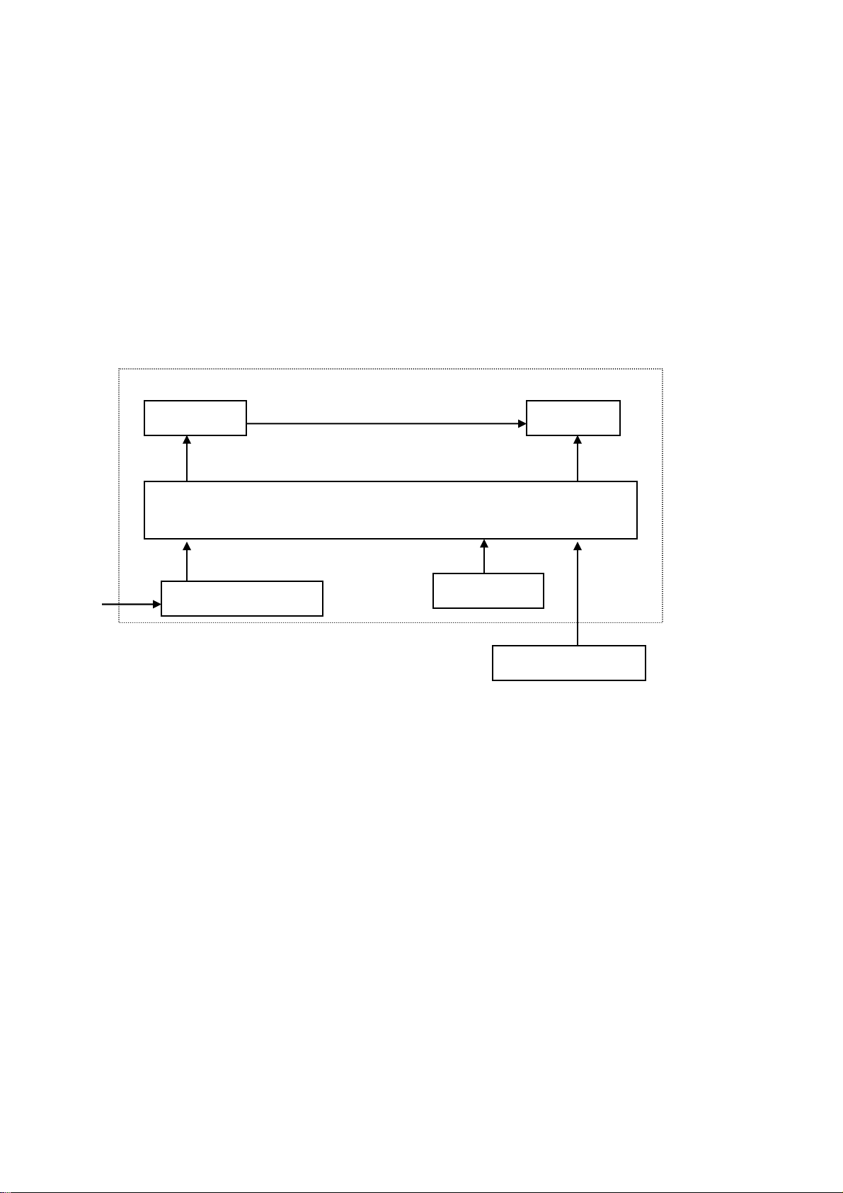
1-2 LCD MONITOR DESCRIPTION
The LCD MONITOR will contain an main board, an inverter board, a power switch board and a keyboard.
The main board will house the flat panel control logic, brightness control logic, DDC and DC-DC conversion
to supply the appropriate power to the whole board and LCD panel, and transmitting TTL level signals into
LCD Module to drive the LCD display circuit.
The inverter board will drive the two CCFLs (Cold Cathode Fluorescent Tube).
The switching power board will provides the power ON/OFF control over the whole monitor and control for
DPMS LED indicator.
The function keyboard will provides the OSD control signal to the Main Board.
Monitor Block Diagram
Inverter Flat Panel
ADAPTER
1-3 Interface Connectors
(A) Power Cable
(B) Video Signal Connectors and Cable
CCFT Drive.
Main Board
Keyboard
HOST Computer
Video signal, DDC
4
Page 6

2. PRECAUTIONS AND NOTICES
2-1 ASSEMBLY PRECAUTION
(1) Please do not press or scratch LCD panel surface with anything hard. And do not soil LCD panel surface
by touching with bare hands (Polarizer film, surface of LCD panel is easy to be flawed)
In the LCD panel, the gap between two glass plates is kept perfectly even to maintain display
characteristic and reliability. If this panel is subject to hard pressing, the following occurs :
(a) Uniform color (b) Orientation of liquid crystal becomes disorder
(2) Please wipe out LCD panel surface with absorbent cotton or soft cloth in case of it being soiled.
(3) Please wipe out drops of adhesive like saliva and water in LCD panel surface immediately.
They might damage to cause panel surface variation and color change.
(4) Do not apply any strong mechanical shock to the LCD panel.
2-2 OPERATING PRECAUTIONS
(1) Please be sure to unplug the power cord before remove the back-cover. (be sure the power is turn-off)
(2) Please do not change variable resistance settings in MAIN-BOARD, they are adjusted to the most
suitable value. If they are changed, it might happen LUMINANCE does not satisfy the white balance
spec.
(3) Please consider that LCD backlight takes longer time to become stable of radiation characteristic in low
temperature than in room temperature.
(4) Please pay attention to displaying the same pattern for very long-time. Image might stick on LCD.
2-3 STORAGE PRECAUTIONS
(1) When you store LCD for a long time, it is recommended to keep the temperature between 0℃-40℃
without the exposure of sunlight and to keep the humidity less than 90% RH.
(2) Please do not leave the LCD in the environment of high humidity and high temperature such as 60℃
90%RH.
(3) Please do not leave the LCD in the environment of low temperature; below -15℃.
2-4 HIGH VOLTAGE WARNING
The high voltage was only generated by INVERTER module, if carelessly contacted the transformer on this
module, can cause a serious shock. (the lamp voltage after stable around 600V, with lamp current around
8mA, and the lamp starting voltage was around 1500V, at Ta=25℃)
5
Page 7
3. OPERATING INSTRUCTIONS
This procedure gives you instructions for installing and using the TFT5017/FP5017 LCD monitor display.
1. Position the display on the desired operation and plug the power cord into a convenient AC outlet.
Three-wire power cord must be shielded and is provided as a safety precaution as it connects the chassis
and cabinet to the electrical conduct ground. If the AC outlet in your location does not have provisions
for the grounded type plug, the installer should attach the proper adapter to ensure a safe ground
potential.
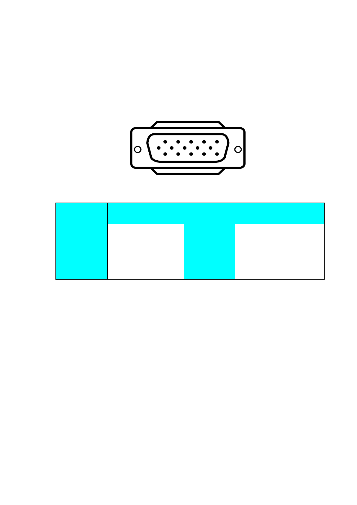
2. Connect the 15-pin color display shielded signal cable to your signal system device and lock both
screws on the connector to ensure firm grounding. The connector information is as follow:
1
6
11 15
5
10
15 - Pin Color Display Signal Cable
PIN NO.
DESCRIPTION
PIN NO.
DESCRIPTION
1. RED 9. 5V power from VGA-card
2. GREEN 10. GND
3. BLUE 11. NC
4. NC 12. SDA
5. GND 13. HORIZ. SYNC
6. GND-R 14. VERT. SYNC
7. GND-G 15. SCL
8. GND-B
3. Apply power to the display by turning the power switch to the "ON" position and allow about thirty
seconds for Panel warm-up. The Power-On indicator lights when the display is on.
4. With proper signals feed to the display, a pattern or data should appear on the screen, adjust the
brightness and contrast to the most pleasing display, or press auto-key to get the best picture-quality.
5. This monitor has power saving function following the VESA DPMS. Be sure to connect the signal cable
to the PC.
6. If your TFT5017/FP5017 LCD monitor requires service, it must be returned with the power cord.
6
Page 8
4. ADJUSTMENT
4-1 ADJUSTMENT CONDITIONS AND PRECAUTIONS
1. Approximately 30 minutes should be allowed for warm up before proceeding.
2. Adjustments should be undertaken only on following function :Horizontal Position, Vertical Position,
Clock, Clock Phase, Brightness, Contrast, Color Select (6500°K, 9300°K, and Custom Color)
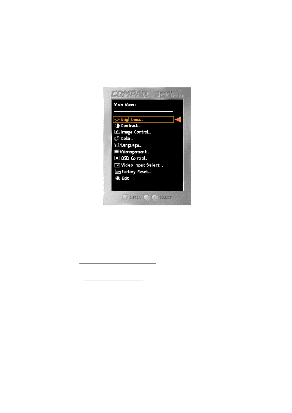
4-2 ADJUSTMENT METHOD
Press MENU key to show OSD window or select function, and Left/Right key to switch the function controls
or done the adjustment.
1. White-Balance, Luminance adjustment
Before started adjust white balance ,lets setting the Chroma-7120 MEM. Channel 1 to 9300 color and
MEM. channel 2 to 6500 color, how to setting MEM.channel you can reference to chroma 7120 user
guide or simple use “ SC” key and “ NEXT” key to modify xyY value and use “ID” key to modify your
own description
Following is the step to do white-balance adjust
Press MENU key and Right key for 2 seconds at power on (replug power cord) will be in factory mode.
I. Bias (Low luminance) adjustment :
Wait for message “ Pass” appear then adjust OSD contrast and brightness to “90”.
II. Gain (High light) adjustment :
a. adjust 9300 color-temperature
change chroma-7120 to channel 1,Switch the chroma-7120 to RGB-mode(with press “MODE” )
,and selected OSD item “F” (at OSD right down corner), Enter AOC Compaq1 Menu
The lcd-indicator will show x = 281 ±10, y = 311 ±10, Y = 230 ±5 cd/m
Adjust 9300k RGB until R=100, G=100, B=100, and then switch the chroma-7120 to xyY
mode
(With press “MODE” )
b. adjust 6500 color-temperature
change chroma-7120 to channel 2, Switch the chroma-7120 to RGB-mode(with press
“MODE” ),
The lcd-indicator will show x = 313 ±10, y = 329 ±10, Y = 230 ±5 cd/m
Adjust 6500k RGB until R=100, G=100, B=100, and then switch the chroma-7120 to xyY
mode
(With press “MODE” )
Press POWER-key off-on to quit from factory mode ( in USER-mode, the OSD location was
placed at middle of screen)
2
2
7
Page 9

2. Clock adjustment
Set the Chroma at pattern 63 (cross-talk pattern) or WIN98/95 shut-down mode (dot-pattern).
Adjust until the vertical-shadow as wide as possible or no visible.
This function is adjust the PLL divider of ADC to generate an accurate pixel clock
Example : Hsyn = 31.5KHz Pixel freq. = 25.175MHz (from VESA spec)
The Divider number is (N) = (Pixel freq. x 1000)/Hsyn
From this formula, we get the Divider number, if we fill this number in ADC register (divider register),
the PLL of ADC will generate a clock which have same period with above Pixel freq.(25.175MHz) the
accuracy of this clock will effect the size of screen.(this clock was called PIXEL-CLOCK)
3. Phase adjustment
Set the Chroma at pattern 63 (cross talk pattern) or WIN98/95 shut down mode (dot-pattern).
Adjust the horizontal interference as less as possible
This function is adjust the phase shift of PIXEL-CLOCK to acquire the right pixel data .
If the relationship of pixel data and pixel clock not so match, we can see the horizontal interference at
screen only at crosstalk pattern and dot pattern we can find this phenomena, other pattern the affect is
very light
4. H/V-Position adjustment
Set the Chroma at pattern 1 (crosshatch pattern) or WIN98/95 full-white pattern confirm above 2
functions (clock & focus) was done well, if that 2 functions failed, the H/V position will be failed too.
Adjust the four edge until all four-edges are visible at the edge of screen.
5. MULTI-LANGUAGE function
There have 6 language for selection, press “MENU” to selected and confirm , press “ LEFT” or
“ RIGHT” to change the kind of language.
6. Reset function
Clear each old status of auto-configuration and re-do auto-configuration ( for all mode)
This function also recall 6500 color-temperature , if the monitor status was in “ Factory-mode” this reset
function will clear Power-on counter too.
7. OSD-LOCK function
The OSD functionality shall be enabled or disabled by pressing the “menu” button and holding it for 10
seconds. Upon disabling the OSD, an OSD message of “OSD Lockout” shall be displayed for 10
seconds. When the OSD is locked and any OSD button is pressed, the OSD message “OSD Locked”
shall be displayed for an additional 10 seconds. When the OSD is locked, holding the OSD button for
10 seconds will unlock the OSD and display the main menu.
8. View Hours Total Operation and Hours Backlight On ( if not necessary , not suggest to entry Service
Mode,it is entered by pressing the power switch while the menu button is held in.)
Total Hours track and record the total hours that it has been powered up. This value shall be stored
in the system memory. The Hours Total Operation shall be incremented 31 minutes after power is
applied, and once each hour after that while power is still active.
Backlight Hours track and record the number of hours the backlight tubes have had power applied to
them. This shall be independent of the brightness or contrast controls. The Hours Backlight On shall
be incremented 31 minutes after power has been continuously applied to the backlight, and once each
hour after that while power is still applied to the backlight.
The Backlight
life time was guarantee minimal 30000 hours, the maintainer can check the record only in Service Mode.
pressing the power switch while the menu button is held in will be in f service mode.
“Reset Total Hours “ clear the powered up counter to zero hours.
“Reset Backlight Hours “ clear Backlight
4-3 MAIN ADJUSTMENTS
Power Key : Press to turn on or off the monitor.
Left Key : Press to perform automatic calculated CLOCK, PHASE, H/V POSITION, but no affect the color-
temperature
Left/Right Key : press to perform select function or adjustment.
MENU Key : press to show the OSD menu at the monitor or to confirm your function selection
Hours was used to record how long the backlight of panel already working, the backlight
Hours counter to zero hours.
8
Page 10

5. CIRCUIT-DESCRIPTION
5-1 SPECIAL FUNCTION with PRESS-KEY
Press MENU key and Right key, at POWER-ON: set to FACTORY-mode, when we want to adjust white-
balance with rs232-port.
Press POWER-key off-on : CANCEL above function(quit from factory mode) and set to user-mode.
Press MENU key 10seconds : Enable/ Disable OSD-LOCK function
OSD-INDEX EXPLANATION
1. CABLE NOT CONNECTED :Check video cable.
2. INPUT NOT SUPPORT :
a. INPUT frequency out of range : H > 61kHz, v > 75Hz or H < 30kHz, v < 56Hz
b. INPUT frequency out of VESA-spec. (out of tolerance too far)
3. UNSUPPORT mode, try different Video-card Setting :
Input frequency out of tolerance, but still can catch-up by our system (if this message show, that means,
this is new-user mode, AUTO-CONFIG will disable)
5-2 SIMPLE-INTRODUCTION about TFT5017/FP5017 chipset
1. GM2115 (Genesis all-in-one solution for ADC, OSD,MCU,TCON,scalar and interpolation) :
USE for computer graphics images to convert analog RGB data to digital data for interpolation process,
zooming, OSD font & overlay and generate drive-timing for LCD-PANEL,
2. W49F002 (Winbond flash memory, with 64k Rom-size) :
Use for store firmware, the firmware include calculate frequency, pixel-dot , detect change mode, rs232communication, power-consumption control, OSD-index warning…etc.
3. M24C02 (MicroChip IC) :
EePROM type, 1K ROM-SIZE, for saving DDC-CONTENT.
4. M24C16 (MicroChip IC) :
EePROM type, 4K ROM-SIZE, for saving AUTO-config data, White-balance data, and Power-key status,
backliaht on-counter data and power up –counter data.
5. BA9741F (swintching regulator 12V to 5V and 12V to 3.3V) :
6. RT9164-25CG (RICH TEK brand regulator 5V to 2.5V)
MODULE-TPYE COMPONENT :
1. ADAPTER : CONVERSION-module to convert AC 90V-265V to 12VDC, with 3.33 AMP
2. INVERTER : CONVERSION-module to convert DC 12V to High-Voltage around 1600V, with frequency
30K-50Khz, 7mA-10mA
9
Page 11
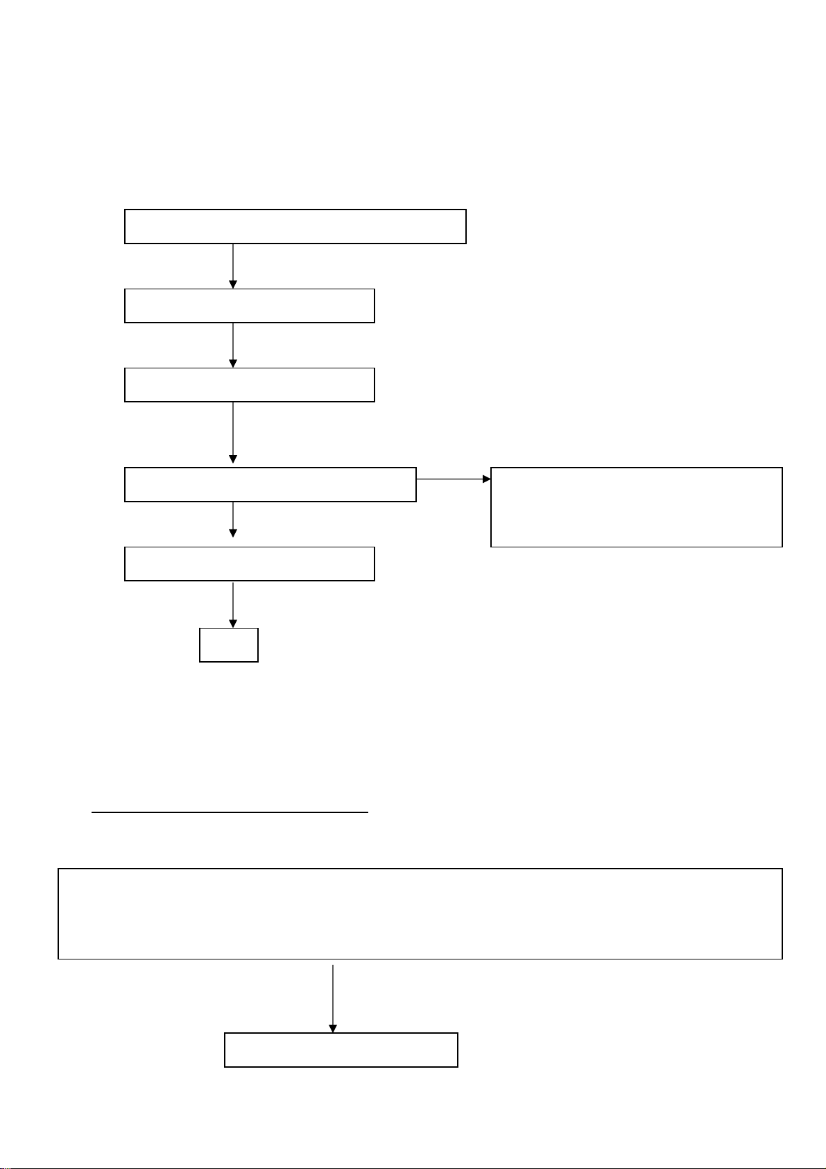
6. Trouble-Shooting
**Use the PC Win 2000/98/95 white pattern, with some icon on it, and Change the Resolution to 640x480 60
Hz / 31 KHz
I. NO SCREEN APPEAR
INVERTER BLOCK TROUBLE SHOOTING
Check the CN6 : Pin 1& Pin2 = 12v for Inverter power supply
CN6 : Pin 4 = Lamp current control Æ must have 0 volt to 3.3 volt Voltage variable when adjust Brightness
CN6 : Pin 6 = Inverter on-off control Æ must have 3.3volt when power switch on ( LED green ) and must have 0 volt When
power switch off ( LED orange)
Check all above status is meet or not ?
Check Adapter module have 12V output?
Check FPC cable loose or tight ?
Check Inverter Block Trouble shooting
Check Dc to Dc block trouble shooting
Check Scalar Trouble shooting
End
YES
YES
ok
ok
ok
Replace Inverter module to new one
If the product name of this monitor is
T563KCDHKCCPA or T563KCDHKCCPN
Check Dc to Dc Module block trouble shooting
no
10
Page 12
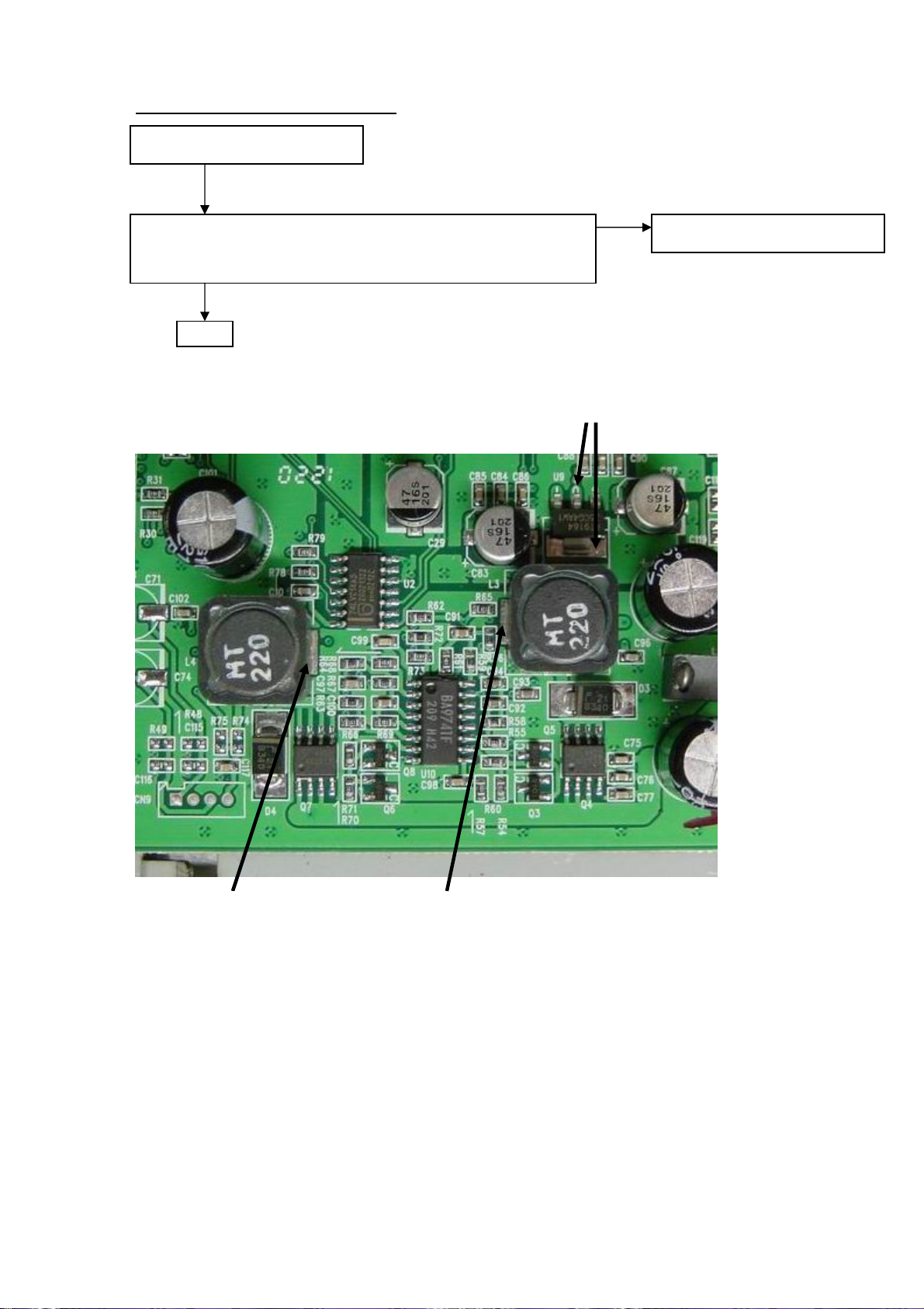
y
DC to DC block trouble shooting
Check CN12 have 12v input ?
CHECK L3 have 3.3V output & L4 have 5V output?
U9 Pin2 have 2.5V output
End
es no
Replace relative component
U9pin 2 = 2.5V
L3 pin 1 = 3.3VL4 pin 1 = 5V
11
Page 13

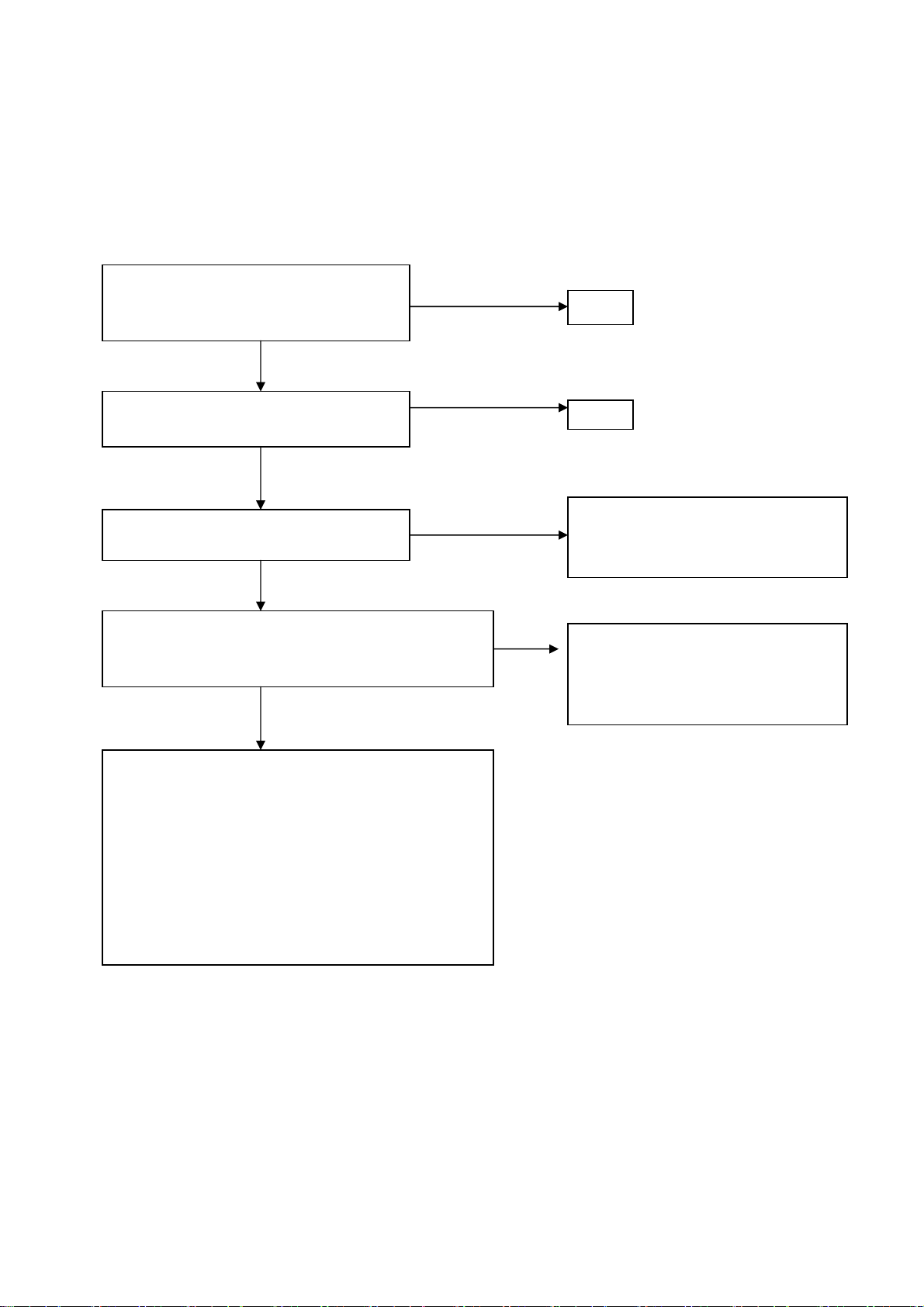
y
y
y
yes
yes yes
d
DC to DC Module block trouble shooting
Check U11Pin2 or Pin3 have 5V input ?
es
Check U11Pin4 have 3.3V input ? (when power on)
Check U11Pin4 have 0V input ? (when power off)
es
Check U11Pin7 have 9V output ?
es
Check U11Pin9 have -6V output ?
Check U11Pin12 have 3.6V output ?
Check U11Pin14 have 18V output ?
En
no
no
no
no
no
Replace Dc to Dc Module (U11)
component
U11 pin 12 = 3.6V
U11 pin 2 & 3 = 5V
U11 pin 4 = 3.3V(power on) or
0V(power off)
U11 pin 7 = 9V
U11 pin 12 = 3.6V
U11pin 9 = -6V
12
Page 14

y
y
y
y
y
y
AUDIO-MODULE Trouble shooting chart
NO VOICE OUTPUT
Plug-out the DC power , make sure
the monitor is in OFF status .
Use OHM-METER measure U8 pin 3, 5
(channel-A ) is speaker well connected?
Measure U8 pin 16,18 ( channel B) is speaker
well connected ?
Plug-in the DC power, set the monitor
ON status .
Check U8 pin 4,17 = VDD 5V
Check CN8 pin 1,4 have signal ?
Check U8 pin 6,15 have signal ?
Check U8 pin 3,5,16,18 have
signal ?
End
es
es
es
es
es
es
no
Check CN7,CN11 is well
connected?
YES
Check is speaker open circuit ?
no
Check Dc to Dc block 5V
no
Replace Audio Cable
no
Replace U8
13
Page 15

Scalar BLOCK TROUBLE SHOOTING
Press the Power switch , Check the LED will switch from
Green to dark or Orange to dark
Unplug the Signal cable ,there must have OSD message show
“Cable not connected”
yes
The Mainboard & Flash part is working, please check your PC signal , may be the
frequency out of range or in sleep mode.
Replace U5
Replace the Mainboard or replace
GM2115
14
Page 16
pei)
II.ALL SCREEN HAS INTERFERENCES OR NOISE, CAN’T BE FIXED BY AUTO
KEY
** NOTE: There is so many kind of interferences, 1). One is cause by some VGA-CARD that not meet VESA spec
or power grounding too bad that influence our circuit
2).other is cause by external interferences, move the monitor far from electronic equipment.( rarely
happened)
Use DOT-pattern, or win2000/98/95 shutdown mode pattern, press “AUTO” key, was
the interferences disappear ??
Adjust “FOCUS” step by step, until the
horizontal interferences disappear
Does your signal-cable have an additional
cable for extension ??
Does your noise only exist in one mode only?
(ex: only at 1024x768 @ 75 Hz, other is normal)
That was cause by you VGA-CARD setting, your VGA
card timing backporch/frontporch exceed vesa timing too
far, for some new AGP-VGA-CARD such situation
always happened
So in your control-panel icon ,select monitor ,setting ,
advance ,screen-adjust,at
Size icon, increase step by step slowly, press “”AUTO”
key every step you increase the SIZE . repeat the
procedure( increase/decrease SIZE one-step and press
AUTO) until the interferences disappear, press “APPLY”
to save in your VGA
NO additional extension cable
Yes, only happened on one mode
Yes, has extension
END
END
Put away the additional cable
May be the additional cable grounding is
not quite well
Change the Signal-cable to new-one or
Try other brand VGA-CARD
(make sure just only that brand VGACARD has this problem ,contact RDtai
15
Page 17

III. DOS MODE has jitter
NOTE :the rule of doing AUTO-CONFIGURATION : must be a full-size screen, if the screen not full , the autoconfiguration will fail. So in dos mode ,just set your “CLOCK” in OSD-MENU to zero or use some full screen edit
file (ex: PE2, HE) and press “AUTO”
IⅤ. THERE WAS SNOW PHENOMENA or BRIGHT NOISE ON THE SCREEN
When use pattern 32 Gray-scale / or 16 Gray scale, there is a snow phenomena on the screen (like a noise spread
inside) that means data missing, may be cause by FPC loose, or resistor array cold-solder
Check the FPC loose or tight or Replace a new FPC
Re solder all resistor array from LP1 – LP13
Replace Mainboard to new one
V. THE PANEL LUMINANCE WAS DOWN
Set Contrast & brightness =maximal, RGB= 50
Quit from OSD-screen, measured Y(luminance)
With chroma 7120, check Y= 250±10 CD/M2 ?
If Y can reach >230 cd/m2 that means
The lamp still working well, so we just re-do the
white-balance process
Please refer to page 7
If the Y less than 160 cd/m2 (after the Brightness &
contrast = max) then change the LAMP of panel
16
Page 18

17
Page 19
18
Page 20

19
Page 21

20
Page 22
21
Page 23

22
Page 24

23
Page 25
24
Page 26

25
Page 27

26
Page 28
27
Page 29

28
Page 30
29
Page 31

30
Page 32
31
Page 33

32
Page 34

33
Page 35

34
Page 36

35
Page 37

36
Page 38

37
Page 39

38
Page 40

39
Page 41

40
Page 42

41
Page 43

42
Page 44

43
Page 45
44
Page 46

45
Page 47

46
Page 48

47
Page 49

48
Page 50

49
Page 51

50
Page 52

51
Page 53

52
Page 54

53
Page 55

54
Page 56

55
Page 57

56
Page 58

57
Page 59

58
Page 60

59
Page 61

60
Page 62
61
Page 63

62
Page 64

63
Page 65

64
Page 66

65
Page 67

66
Page 68

67
Page 69

68
Page 70

69
Page 71

70
Page 72

71
Page 73

7. MECHANICAL OF CABINET FRONT DIS-ASSEMBLY
72
Page 74

8.PARTS LISTING
1.FT5017 FOR HANNSTAR*83 PANEL
PARTS LIST OF CABINET
LOCATION
CBPC560KHDC3 CONVERSION BOARD FOR T5
KEPC560KB1 KEY BOARD FOR T563K*COM
7L 1 L 6
15L5689 2 A GND CLAMP
15L5753 1 MAIN BRACKET
33L4438 A6 T LOGO COVER
40L 150716 2A ID LABEL
40L 152509 RECYCLE LABEL
40L 152512 RECYCLE LABEL
40L 154 14 1 CABINET LABEL
40L 457716 1A TCO99 LABEL
40L 581 26704
40L 581716 1A CARTON LABEL
41L 68508 A
41L1500716 4B DOC KIT(272943-292)
44L3231 15 EVA WASHER
44L3231501
44L3231506
44L3510 1EPE EPE-R
44L3510 2EPE EPE-L
44L3510 5 U TYPE PAPER SHEET
44L3510716 4B CARTON
44L9003 9 CORNER PAPER
45L 77 3
45L 77500 BARCODE RIBBON
45L 77501 BARCODE RIBBON
45L 88607 CP PE BAG
45L 88609 EPE COVER
52L 1185 16 MIDDLE TAPE
52L 1186 SMALL TAPE
52L6020 2 PROTECT FILM
52L6021 3
71L 100 19 WS ZP 5*12*25
79L L15 12 E INVERTER BY EMAX
80L L15 11 LS ADAPTOR BY LINE SHIN
80L L15 11 LT ADAPTER
85L 601 1 SHIELD CASE
89L 173L15 28 SIGNAL CABLE
89L 176 40 2 FFC CABLE 40P 50mm
89L401A18NISB POWER CORD
TF1562-S3 SPECIFICATION
刺狾
酠繷 FOR CARTON/PALLET
恨
旧筿獁粗
旧筿獁粗
ゴ 饯
荡絫
73
Page 75

M1L 330 4128 SCREW M3X4
M1L 330 6128 SCREW
M1L1030 12128 SCREW M3X12
M1L1740 10 47 SCREW M4X10
Q1L1030 8 47 SCREW 3mmX8
Q1L1030 10128 SCREW
705L563KB34002
750LLH50X83 HANNSTAR 15" S.I PANEL
LCD 催 ASS'Y
PARTS LIST OF BACK COVER ASS’Y
LOCATION 705L563KB34002 SPECIFICATION
12L 387 2 RUBBER FOOT
15L5752 1 BASE BRACKET
15L5754 1 VESA BRACKET
15L5755 1 STAND BRACKET
33L4434 1 LENS
33L4435 A5 L KEY PAD
33L4436 A7 L POWER BUTTON
33L4439 A6 L HOOL COVER
34L 968AA5 T FRONT PANEL
34L 970AA6 1T BACK COVER
34L 971 A6 B PEDESTAL
37L 456 1 HINGE
M1L1740 8128 SCREW M4X8
Q1L 340 10128 SCREW 4X10mm
CQ1L 140 8128 SCREW
PARTS LIST OF CONVERSION BOARD
LOCATION CBPC560KHDC3 SPECIFICATION
AI560KHDC3 CBPC AUTO INS. FOR T563
CN5 33L3802 7 WAFER EH-7
CN6 33L8022 6A H HEADER FEMALE 6P
49L 51 1A
55L 100600 A
55L 100603
U5 56L1133 35 H1 W49F 002UP
C101 67L 305331 4 330UF +-20% 25V
C79 67L 305331 4 330UF +-20% 25V
C95 67L 305331 4 330UF +-20% 25V
L5 71L 55 28 FERRITE BEAD 7.62*5.08*
CN12 88L 304 8K DC POWER JACK SCD-014A
CN1 88L 35315F HS D-SUB 15PIN FEMALE
X1 93L 22 53 CRYSTAL 14.318MHzHC-49U
簕猳
ň 聁瞜奎
к て瞜奎
74
Page 76

PARTS LIST OF CONVERSION BOARD AUTO INSERTION
LOCATION AI560KHDC3 SPECIFICATION
CN3 33L8019 40 CONNECTOR 40P SMT
CN4 33L8019 40 CONNECTOR 40P SMT
55L 23520 IPA
55L 100600 A
55L 100602
U3 56L 562 17 GM2115
U7 56L 585 4 AIC1117-33CY SMT
U9 56L 585 5 RT9164-25CG
U10 56L 622 1 BA9741F-SMT
U6 56L1133 33 M24C16-MN6T SMT
U1 56L1133 34 M24C02-WMN6T SMT
U2 56L4LVC 14 F 74LVC14 BY FAIRCHILD
U2 56L4LVC 14 P 74LVC14ADT
Q2 57L 417 4 PMBS3904/PHILIPS-SMT
Q3 57L 417 4 PMBS3904/PHILIPS-SMT
Q6 57L 417 4 PMBS3904/PHILIPS-SMT
Q5 57L 417 6 PMBS3906/PHILIPS-SMT
Q8 57L 417 6 PMBS3906/PHILIPS-SMT
Q1 57L 763 1 A03401 SOT23 BY AO
Q4 57L 763 2 AO4403 SO-8 BY AOS SMT
Q7 57L 763 2 AO4403 SO-8 BY AOS SMT
RP4 61L 125103 8 CHIP AR 8P4R 10KOHM +-5
RP6 61L 125472 8 CHIP AR 8P4R 4.7K OHM+-
R57 61L0603100 CHIP 10 OHM 1/16W
R1 61L0603101 CHIPR 100 OHM +-5% 1/16
R2 61L0603101 CHIPR 100 OHM +-5% 1/16
R5 61L0603101 CHIPR 100 OHM +-5% 1/16
R6 61L0603101 CHIPR 100 OHM +-5% 1/16
R60 61L0603101 CHIPR 100 OHM +-5% 1/16
R71 61L0603101 CHIPR 100 OHM +-5% 1/16
R8 61L0603101 CHIPR 100 OHM +-5% 1/16
R9 61L0603101 CHIPR 100 OHM +-5% 1/16
R29 61L0603102 CHIPR 1K OHM +-5% 1/16W
R37 61L0603102 CHIPR 1K OHM +-5% 1/16W
R54 61L0603102 CHIPR 1K OHM +-5% 1/16W
R70 61L0603102 CHIPR 1K OHM +-5% 1/16W
R14 61L0603103 CHIPR 10K OHM +-5% 1/16
R3 61L0603103 CHIPR 10K OHM +-5% 1/16
R30 61L0603103 CHIPR 10K OHM +-5% 1/16
R31 61L0603103 CHIPR 10K OHM +-5% 1/16
R35 61L0603103 CHIPR 10K OHM +-5% 1/16
R36 61L0603103 CHIPR 10K OHM +-5% 1/16
R38 61L0603103 CHIPR 10K OHM +-5% 1/16
R39 61L0603103 CHIPR 10K OHM +-5% 1/16
ň 聁瞜奎
奎籌
75
Page 77

R4 61L0603103 CHIPR 10K OHM +-5% 1/16
R40 61L0603103 CHIPR 10K OHM +-5% 1/16
R45 61L0603103 CHIPR 10K OHM +-5% 1/16
R68 61L0603103 CHIPR 10K OHM +-5% 1/16
R73 61L0603103 CHIPR 10K OHM +-5% 1/16
R78 61L0603103 CHIPR 10K OHM +-5% 1/16
R79 61L0603103 CHIPR 10K OHM +-5% 1/16
R43 61L0603104 CHIPR 100K OHM +-5% 1/1
R65 61L0603123 CHIP 12K OHM 1/16W
R61 61L0603183 CHIP 18K OHM 1/16W
R69 61L0603183 CHIP 18K OHM 1/16W
R16 61L0603202 CHIPR 2K OHM+-5% 1/16W
R17 61L0603202 CHIPR 2K OHM+-5% 1/16W
R62 61L0603203 CHIPR 20K OHM+-5% 1/16W
R41 61L0603221 CHIPR 220 OHM+-5% 1/16W
R42 61L0603221 CHIPR 220 OHM+-5% 1/16W
R24 61L0603272 CHIP 2.7K OHM 1/16W
R76 61L0603301 CHIP 300 OHM 1/16W
R77 61L0603301 CHIP 300 OHM 1/16W
R58 61L0603303 CHIP 30K OHM 5% 1/16W
R63 61L0603303 CHIP 30K OHM 5% 1/16W
R72 61L0603303 CHIP 30K OHM 5% 1/16W
R10 61L0603470 CHIPR 47 OHM +-5% 1/16W
R18 61L0603470 CHIPR 47 OHM +-5% 1/16W
R19 61L0603470 CHIPR 47 OHM +-5% 1/16W
R7 61L0603470 CHIPR 47 OHM +-5% 1/16W
R15 61L0603472 CHIPR 4.7K OHM +-5% 1/1
R23 61L0603472 CHIPR 4.7K OHM +-5% 1/1
R25 61L0603472 CHIPR 4.7K OHM +-5% 1/1
R32 61L0603472 CHIPR 4.7K OHM +-5% 1/1
R33 61L0603472 CHIPR 4.7K OHM +-5% 1/1
R44 61L0603472 CHIPR 4.7K OHM +-5% 1/1
R56 61L0603473 CHIP 47K OHM 1/16W
R59 61L0603473 CHIP 47K OHM 1/16W
R64 61L0603473 CHIP 47K OHM 1/16W
R67 61L0603473 CHIP 47K OHM 1/16W
R55 61L0603563 CHIP 56K OHM 1/16W
R66 61L0603563 CHIP 56K OHM 1/16W
R11 61L0603750 9F 75OHM 1%
R12 61L0603750 9F 75OHM 1%
R13 61L0603750 9F 75OHM 1%
CP1 65L 600220 8T 22PF+-10% 50V 8P NPO SM
CP10 65L 600220 8T 22PF+-10% 50V 8P NPO SM
CP2 65L 600220 8T 22PF+-10% 50V 8P NPO SM
CP3 65L 600220 8T 22PF+-10% 50V 8P NPO SM
CP4 65L 600220 8T 22PF+-10% 50V 8P NPO SM
CP5 65L 600220 8T 22PF+-10% 50V 8P NPO SM
CP6 65L 600220 8T 22PF+-10% 50V 8P NPO SM
76
Page 78

CP7 65L 600220 8T 22PF+-10% 50V 8P NPO SM
CP8 65L 600220 8T 22PF+-10% 50V 8P NPO SM
CP9 65L 600220 8T 22PF+-10% 50V 8P NPO SM
C105 65L0603102 32 CHIP 1000PF 50V X7R
C106 65L0603102 32 CHIP 1000PF 50V X7R
C107 65L0603102 32 CHIP 1000PF 50V X7R
C108 65L0603102 32 CHIP 1000PF 50V X7R
C109 65L0603102 32 CHIP 1000PF 50V X7R
C110 65L0603102 32 CHIP 1000PF 50V X7R
C117 65L0603102 32 CHIP 1000PF 50V X7R
C121 65L0603102 32 CHIP 1000PF 50V X7R
C122 65L0603102 32 CHIP 1000PF 50V X7R
C125 65L0603102 32 CHIP 1000PF 50V X7R
C62 65L0603102 32 CHIP 1000PF 50V X7R
C75 65L0603102 32 CHIP 1000PF 50V X7R
C86 65L0603102 32 CHIP 1000PF 50V X7R
C90 65L0603102 32 CHIP 1000PF 50V X7R
C1 65L0603103 32 0.01UF+-10% 50V X7R
C2 65L0603103 32 0.01UF+-10% 50V X7R
C4 65L0603103 32 0.01UF+-10% 50V X7R
C5 65L0603103 32 0.01UF+-10% 50V X7R
C6 65L0603103 32 0.01UF+-10% 50V X7R
C7 65L0603103 32 0.01UF+-10% 50V X7R
C76 65L0603103 32 0.01UF+-10% 50V X7R
C85 65L0603103 32 0.01UF+-10% 50V X7R
C89 65L0603103 32 0.01UF+-10% 50V X7R
C10 65L0603104 12 0.1UF +-10% 16V X7R
C102 65L0603104 12 0.1UF +-10% 16V X7R
C13 65L0603104 12 0.1UF +-10% 16V X7R
C14 65L0603104 12 0.1UF +-10% 16V X7R
C15 65L0603104 12 0.1UF +-10% 16V X7R
C16 65L0603104 12 0.1UF +-10% 16V X7R
C18 65L0603104 12 0.1UF +-10% 16V X7R
C19 65L0603104 12 0.1UF +-10% 16V X7R
C20 65L0603104 12 0.1UF +-10% 16V X7R
C21 65L0603104 12 0.1UF +-10% 16V X7R
C22 65L0603104 12 0.1UF +-10% 16V X7R
C23 65L0603104 12 0.1UF +-10% 16V X7R
C24 65L0603104 12 0.1UF +-10% 16V X7R
C25 65L0603104 12 0.1UF +-10% 16V X7R
C26 65L0603104 12 0.1UF +-10% 16V X7R
C27 65L0603104 12 0.1UF +-10% 16V X7R
C28 65L0603104 12 0.1UF +-10% 16V X7R
C3 65L0603104 12 0.1UF +-10% 16V X7R
C32 65L0603104 12 0.1UF +-10% 16V X7R
C33 65L0603104 12 0.1UF +-10% 16V X7R
C34 65L0603104 12 0.1UF +-10% 16V X7R
C35 65L0603104 12 0.1UF +-10% 16V X7R
77
Page 79

C36 65L0603104 12 0.1UF +-10% 16V X7R
C37 65L0603104 12 0.1UF +-10% 16V X7R
C38 65L0603104 12 0.1UF +-10% 16V X7R
C39 65L0603104 12 0.1UF +-10% 16V X7R
C40 65L0603104 12 0.1UF +-10% 16V X7R
C41 65L0603104 12 0.1UF +-10% 16V X7R
C42 65L0603104 12 0.1UF +-10% 16V X7R
C43 65L0603104 12 0.1UF +-10% 16V X7R
C44 65L0603104 12 0.1UF +-10% 16V X7R
C46 65L0603104 12 0.1UF +-10% 16V X7R
C47 65L0603104 12 0.1UF +-10% 16V X7R
C48 65L0603104 12 0.1UF +-10% 16V X7R
C49 65L0603104 12 0.1UF +-10% 16V X7R
C50 65L0603104 12 0.1UF +-10% 16V X7R
C52 65L0603104 12 0.1UF +-10% 16V X7R
C56 65L0603104 12 0.1UF +-10% 16V X7R
C57 65L0603104 12 0.1UF +-10% 16V X7R
C58 65L0603104 12 0.1UF +-10% 16V X7R
C60 65L0603104 12 0.1UF +-10% 16V X7R
C64 65L0603104 12 0.1UF +-10% 16V X7R
C67 65L0603104 12 0.1UF +-10% 16V X7R
C77 65L0603104 12 0.1UF +-10% 16V X7R
C84 65L0603104 12 0.1UF +-10% 16V X7R
C88 65L0603104 12 0.1UF +-10% 16V X7R
C96 65L0603104 12 0.1UF +-10% 16V X7R
C97 65L0603104 12 0.1UF +-10% 16V X7R
C98 65L0603104 12 0.1UF +-10% 16V X7R
C92 65L0603105 17 1UF 16V Y5V
C93 65L0603105 17 1UF 16V Y5V
C94 65L0603105 17 1UF 16V Y5V
C128 65L0603220 31 CHIP 22PF 50V NPO
C129 65L0603220 31 CHIP 22PF 50V NPO
C130 65L0603220 31 CHIP 22PF 50V NPO
C131 65L0603220 31 CHIP 22PF 50V NPO
C132 65L0603220 31 CHIP 22PF 50V NPO
C133 65L0603220 31 CHIP 22PF 50V NPO
C8 65L0603470 32 CHIP 47PF 50V X7R
C9 65L0603470 32 CHIP 47PF 50V X7R
C99 65L0603471 32 CHIP 470PF 50V X7R
C100 65L0603473 32 CHIP 0.047UF 50V X7R
C91 65L0603473 32 CHIP 0.047UF 50V X7R
C53 65L0603509 31 CHIP 5PF+-0.5PF 50V NPO
C55 65L0603509 31 CHIP 5PF+-0.5PF 50V NPO
CP1 65L602K220 8T IRRAY CAP 22PF +-10% 16
CP10 65L602K220 8T IRRAY CAP 22PF +-10% 16
CP2 65L602K220 8T IRRAY CAP 22PF +-10% 16
CP3 65L602K220 8T IRRAY CAP 22PF +-10% 16
CP4 65L602K220 8T IRRAY CAP 22PF +-10% 16
78
Page 80

CP5 65L602K220 8T IRRAY CAP 22PF +-10% 16
CP6 65L602K220 8T IRRAY CAP 22PF +-10% 16
CP7 65L602K220 8T IRRAY CAP 22PF +-10% 16
CP8 65L602K220 8T IRRAY CAP 22PF +-10% 16
CP9 65L602K220 8T IRRAY CAP 22PF +-10% 16
C12 67L 312100 3 SMD 10uf +-20% 16V
C30 67L 312100 3 SMD 10uf +-20% 16V
C51 67L 312100 3 SMD 10uf +-20% 16V
C54 67L 312100 3 SMD 10uf +-20% 16V
C61 67L 312100 3 SMD 10uf +-20% 16V
C59 67L 312101 3 SMD 100UF +-20% 16V
C11 67L 312470 3 SMD EC 47UF 16V +-20%
C17 67L 312470 3 SMD EC 47UF 16V +-20%
C29 67L 312470 3 SMD EC 47UF 16V +-20%
C31 67L 312470 3 SMD EC 47UF 16V +-20%
C45 67L 312470 3 SMD EC 47UF 16V +-20%
C63 67L 312470 3 SMD EC 47UF 16V +-20%
C66 67L 312470 3 SMD EC 47UF 16V +-20%
C83 67L 312470 3 SMD EC 47UF 16V +-20%
C87 67L 312470 3 SMD EC 47UF 16V +-20%
RP1 71L 56A121 8T CHIP BEAD ARRAY 120 OHM
RP10 71L 56A121 8T CHIP BEAD ARRAY 120 OHM
RP11 71L 56A121 8T CHIP BEAD ARRAY 120 OHM
RP12 71L 56A121 8T CHIP BEAD ARRAY 120 OHM
RP2 71L 56A121 8T CHIP BEAD ARRAY 120 OHM
RP3 71L 56A121 8T CHIP BEAD ARRAY 120 OHM
RP5 71L 56A121 8T CHIP BEAD ARRAY 120 OHM
RP7 71L 56A121 8T CHIP BEAD ARRAY 120 OHM
RP8 71L 56A121 8T CHIP BEAD ARRAY 120 OHM
RP9 71L 56A121 8T CHIP BEAD ARRAY 120 OHM
FB1 71L 56Z601 CHIP BEAD 600 OHM 0805
FB2 71L 56Z601 CHIP BEAD 600 OHM 0805
FB3 71L 56Z601 CHIP BEAD 600 OHM 0805
FB4 71L 56Z601 CHIP BEAD 600 OHM 0805
FB5 71L 56Z601 CHIP BEAD 600 OHM 0805
FB6 71L 56Z601 CHIP BEAD 600 OHM 0805
R20 71L 59B121 TB160808B12 SMD
R21 71L 59B121 TB160808B12 SMD
R22 71L 59B121 TB160808B12 SMD
R26 71L 59B121 TB160808B12 SMD
R27 71L 59B121 TB160808B12 SMD
R28 71L 59B121 TB160808B12 SMD
R20 71L 59C121 B FCM1608C-121T03 SMD
R21 71L 59C121 B FCM1608C-121T03 SMD
R22 71L 59C121 B FCM1608C-121T03 SMD
R26 71L 59C121 B FCM1608C-121T03 SMD
R27 71L 59C121 B FCM1608C-121T03 SMD
R28 71L 59C121 B FCM1608C-121T03 SMD
79
Page 81

L3 73L 253136 TE CHOKE COIL BY TECSTAR
L4 73L 253136 TE CHOKE COIL BY TECSTAR
U5 87L 202 32 PLCC CONN 32PIN
ZD1 93L 39146 LL5232B SMT
ZD2 93L 39146 LL5232B SMT
ZD3 93L 39146 LL5232B SMT
ZD4 93L 39146 LL5232B SMT
ZD5 93L 39146 LL5232B SMT
ZD6 93L 39146 LL5232B SMT
ZD1 93L 39147 TZMC5V6-GS08 SMT
ZD2 93L 39147 TZMC5V6-GS08 SMT
ZD3 93L 39147 TZMC5V6-GS08 SMT
ZD4 93L 39147 TZMC5V6-GS08 SMT
ZD5 93L 39147 TZMC5V6-GS08 SMT
ZD6 93L 39147 TZMC5V6-GS08 SMT
ZD1 93L 39149 MLL5232B BY FULL POWER
ZD2 93L 39149 MLL5232B BY FULL POWER
ZD3 93L 39149 MLL5232B BY FULL POWER
ZD4 93L 39149 MLL5232B BY FULL POWER
ZD5 93L 39149 MLL5232B BY FULL POWER
ZD6 93L 39149 MLL5232B BY FULL POWER
D3 93L 60211 SMB340 BY FULL POWER SM
D4 93L 60211 SMB340 BY FULL POWER SM
D1 93L 60222 BAT54CFILM
D1 93L 60230 BAT54C
D2 93L 64 32 LL4148 SMD
D2 93L 6432V LL4148-GS08-SMT
715L 939 1 LCD 15" COMPAQ MAIN BRD
PARTS LIST OF KEY PC BOARD
LOCATION KEPC560KB1 SPECIFICATION
SW1 77L 600 1GHJ KEY SWITCH
SW2 77L 600 1GHJ KEY SWITCH
SW3 77L 600 1GHJ KEY SWITCH
SW4 77L 600 1GHJ KEY SWITCH
D1 81L 12 1 BH 3 PIN LED
CN1 95L8014 7 2 HARNESS
715L 934 1 LCD COMPAQ 17" KEY BRD
80
Page 82

2.FP5017 FOR HANNSTAR*83 PANEL
PARTS LIST OF CABINET
LOCATION
CBPC560KHDC2 CONVERSION BOARD FOR T56
KEPC560KB3 KEY BOARD FOR T563K*COMP
7L 1 L 3 WOODEN PALLET
15L5689 2 A GND CLAMP
15L5753 1 MAIN BRACKET
33L4438 A6 T LOGO COVER
40L 150716 5A ID LABEL
40L 152509 RECYCLE LABEL
40L 152512 RECYCLE LABEL
40L 154 14 1 CABINET LABEL
40L 457716 1A TCO99 LABEL
40L 581 26704
40L 581716 1A CARTON LABEL
40L 581716 4C COLOREAL LABEL
41L 68508 A
41L1500716 7B DOC KIT(266987-A22)
44L3231 15 EVA WASHER
44L3231501
44L3231506
44L3510 1EPE EPE-R
44L3510 2EPE EPE-L
44L3510 5 U TYPE PAPER SHEET
44L3510716 2B CARTON
44L9003 9 CORNER PAPER
45L 77 3
45L 77500 BARCODE RIBBON
45L 77501 BARCODE RIBBON
45L 88607 CP PE BAG
45L 88609 EPE COVER
52L 1185 16 MIDDLE TAPE
52L 1186 SMALL TAPE
52L6020 2 PROTECT FILM
52L6021 3
71L 100 19 WS ZP 5*12*25
78L 311 1 L SPEAKER 4 ohm 2W
78L 311 1 R SPEAKER 4 ohm 2W
79L L15 12 E INVERTER BY EMAX
80L L15 11 LS ADAPTOR BY LINE SHIN
80L L15 11 LT ADAPTER
85L 601 1 SHIELD CASE
89L 173 56 8 AUDIO CABLE 1800mm BLACK
89L 173L15 28 SIGNAL CABLE
TF1562-S3A SPECIFICATION
酠繷 FOR CARTON/PALLET
恨
旧筿獁粗
旧筿獁粗
ゴ 饯
荡絫
81
Page 83

89L 176 40 2 FFC CABLE 40P 50mm
89L410A18N IS POWER CORD WALL-OUT FOR
M1L 330 4128 SCREW M3X4
M1L 330 6128 SCREW
M1L1030 12128 SCREW M3X12
M1L1740 10 47 SCREW M4X10
Q1L1030 8 47 SCREW 3mmX8
Q1L1030 10128 SCREW
705L563KB34001
750LLH50X83 HANNSTAR 15" S.I PANEL (
LCD 催 ASS'Y
PARTS LIST OF BACK COVER ASS’Y
LOCATION
12L 387 2 RUBBER FOOT
15L5752 1 BASE BRACKET
15L5754 1 VESA BRACKET
15L5755 1 STAND BRACKET
33L4434 1 LENS
33L4435 A5 L KEY PAD
33L4437 A7 L POWER BUTTON
33L4439 A6 L HOOL COVER
34L 969AA5 T FRONT PANEL
34L 970AA6 2T BACK COVER
34L 971 A6 B PEDESTAL
37L 456 1 HINGE
M1L1740 8128 SCREW M4X8
Q1L 340 10128 SCREW 4X10mm
Q1L1040 8128 SCREW 4X8mm
Q1L 140 8128 SCREW
705L563KB34001
SPECIFICATION
PARTS LIST OF CONVERSION BOARD
LOCATION CBPC560KHDC2 SPECIFICATION
AI560KHDC2 CBPC AUTO INS.FOR T563K*
CN11 33L3802 2 WAFER EH-2
CN7 33L3802 2 WAFER EH-2
CN5 33L3802 7 WAFER EH-7
CN9 33L3802 4H WAFER 4P RIGHT ANGLE
CN10 33L3802 5H WAFER 5P RIGHT ANELE PIT
CN6 33L8022 6A H HEADER FEMALE 6P
40L 457624 1A CPU LABEL
40L 581624 2B CHASSIS LABEL
49L 51 1A
55L 100600 A
55L 100603
簕猳
ň 聁瞜奎
к て瞜奎
82
Page 84

U5 56L1133 35 H1 W49F 002UP
C101 67L 305331 4 330UF +-20% 25V
C79 67L 305331 4 330UF +-20% 25V
C95 67L 305331 4 330UF +-20% 25V
L5 71L 55 28 FERRITE BEAD 7.62*5.08*6
CN8 88L 302 4C PHONE JACK
CN12 88L 304 8K DC POWER JACK SCD-014A B
CN1 88L 35315F HS D-SUB 15PIN FEMALE
X1 93L 22 53 CRYSTAL 14.318MHzHC-49US
PARTS LIST OF CONVERSION BOARD AUTO INSERTION
LOCATION AI560KHDC2 SPECIFICATION
CN3 33L8019 40 CONNECTOR 40P SMT
CN4 33L8019 40 CONNECTOR 40P SMT
55L 23500
55L 100600 A
55L 100602
U3 56L 562 17 GM2115
U7 56L 585 4 AIC1117-33CY SMT
U9 56L 585 5 RT9164-25CG
U8 56L 621 2 LM4863MTEX
U10 56L 622 1 BA9741F-SMT
U6 56L1133 33 M24C16-MN6T SMT
U1 56L1133 34 M24C02-WMN6T SMT
U2 56L4LVC 14 F 74LVC14 BY FAIRCHILD
U2 56L4LVC 14 P 74LVC14ADT
Q2 57L 417 4 PMBS3904/PHILIPS-SMT
Q3 57L 417 4 PMBS3904/PHILIPS-SMT
Q6 57L 417 4 PMBS3904/PHILIPS-SMT
Q5 57L 417 6 PMBS3906/PHILIPS-SMT
Q8 57L 417 6 PMBS3906/PHILIPS-SMT
Q1 57L 763 1 A03401 SOT23 BY AO
Q4 57L 763 2 AO4403 SO-8 BY AOS SMT
Q7 57L 763 2 AO4403 SO-8 BY AOS SMT
RP4 61L 125103 8 CHIP AR 8P4R 10KOHM +-5%
RP6 61L 125472 8 CHIP AR 8P4R 4.7K OHM+-5
R57 61L0603100 CHIP 10 OHM 1/16W
R1 61L0603101 CHIPR 100 OHM +-5% 1/16W
R2 61L0603101 CHIPR 100 OHM +-5% 1/16W
R5 61L0603101 CHIPR 100 OHM +-5% 1/16W
R6 61L0603101 CHIPR 100 OHM +-5% 1/16W
R60 61L0603101 CHIPR 100 OHM +-5% 1/16W
R71 61L0603101 CHIPR 100 OHM +-5% 1/16W
R8 61L0603101 CHIPR 100 OHM +-5% 1/16W
R9 61L0603101 CHIPR 100 OHM +-5% 1/16W
猳海祡睦警
ň 聁瞜奎
奎籌
83
Page 85

R29 61L0603102 CHIPR 1K OHM +-5% 1/16W
R37 61L0603102 CHIPR 1K OHM +-5% 1/16W
R48 61L0603102 CHIPR 1K OHM +-5% 1/16W
R49 61L0603102 CHIPR 1K OHM +-5% 1/16W
R54 61L0603102 CHIPR 1K OHM +-5% 1/16W
R70 61L0603102 CHIPR 1K OHM +-5% 1/16W
R14 61L0603103 CHIPR 10K OHM +-5% 1/16W
R3 61L0603103 CHIPR 10K OHM +-5% 1/16W
R30 61L0603103 CHIPR 10K OHM +-5% 1/16W
R31 61L0603103 CHIPR 10K OHM +-5% 1/16W
R35 61L0603103 CHIPR 10K OHM +-5% 1/16W
R36 61L0603103 CHIPR 10K OHM +-5% 1/16W
R38 61L0603103 CHIPR 10K OHM +-5% 1/16W
R39 61L0603103 CHIPR 10K OHM +-5% 1/16W
R4 61L0603103 CHIPR 10K OHM +-5% 1/16W
R40 61L0603103 CHIPR 10K OHM +-5% 1/16W
R45 61L0603103 CHIPR 10K OHM +-5% 1/16W
R52 61L0603103 CHIPR 10K OHM +-5% 1/16W
R68 61L0603103 CHIPR 10K OHM +-5% 1/16W
R73 61L0603103 CHIPR 10K OHM +-5% 1/16W
R78 61L0603103 CHIPR 10K OHM +-5% 1/16W
R79 61L0603103 CHIPR 10K OHM +-5% 1/16W
R43 61L0603104 CHIPR 100K OHM +-5% 1/16
R74 61L0603104 CHIPR 100K OHM +-5% 1/16
R75 61L0603104 CHIPR 100K OHM +-5% 1/16
R65 61L0603123 CHIP 12K OHM 1/16W
R61 61L0603183 CHIP 18K OHM 1/16W
R69 61L0603183 CHIP 18K OHM 1/16W
R16 61L0603202 CHIPR 2K OHM+-5% 1/16W
R17 61L0603202 CHIPR 2K OHM+-5% 1/16W
R47 61L0603203 CHIPR 20K OHM+-5% 1/16W
R50 61L0603203 CHIPR 20K OHM+-5% 1/16W
R62 61L0603203 CHIPR 20K OHM+-5% 1/16W
R41 61L0603221 CHIPR 220 OHM+-5% 1/16W
R42 61L0603221 CHIPR 220 OHM+-5% 1/16W
R24 61L0603272 CHIP 2.7K OHM 1/16W
R76 61L0603301 CHIP 300 OHM 1/16W
R77 61L0603301 CHIP 300 OHM 1/16W
R58 61L0603303 CHIP 30K OHM 5% 1/16W
R63 61L0603303 CHIP 30K OHM 5% 1/16W
R72 61L0603303 CHIP 30K OHM 5% 1/16W
R46 61L0603393 39K OHM+-5%
R51 61L0603393 39K OHM+-5%
R10 61L0603470 CHIPR 47 OHM +-5% 1/16W
R18 61L0603470 CHIPR 47 OHM +-5% 1/16W
R19 61L0603470 CHIPR 47 OHM +-5% 1/16W
R7 61L0603470 CHIPR 47 OHM +-5% 1/16W
R15 61L0603472 CHIPR 4.7K OHM +-5% 1/16
84
Page 86

R23 61L0603472 CHIPR 4.7K OHM +-5% 1/16
R25 61L0603472 CHIPR 4.7K OHM +-5% 1/16
R32 61L0603472 CHIPR 4.7K OHM +-5% 1/16
R33 61L0603472 CHIPR 4.7K OHM +-5% 1/16
R44 61L0603472 CHIPR 4.7K OHM +-5% 1/16
R53 61L0603472 CHIPR 4.7K OHM +-5% 1/16
R56 61L0603473 CHIP 47K OHM 1/16W
R59 61L0603473 CHIP 47K OHM 1/16W
R64 61L0603473 CHIP 47K OHM 1/16W
R67 61L0603473 CHIP 47K OHM 1/16W
R55 61L0603563 CHIP 56K OHM 1/16W
R66 61L0603563 CHIP 56K OHM 1/16W
R11 61L0603750 9F 75OHM 1%
R12 61L0603750 9F 75OHM 1%
R13 61L0603750 9F 75OHM 1%
CP1 65L 600220 8T 22PF+-10% 50V 8P NPO SMD
CP10 65L 600220 8T 22PF+-10% 50V 8P NPO SMD
CP2 65L 600220 8T 22PF+-10% 50V 8P NPO SMD
CP3 65L 600220 8T 22PF+-10% 50V 8P NPO SMD
CP4 65L 600220 8T 22PF+-10% 50V 8P NPO SMD
CP5 65L 600220 8T 22PF+-10% 50V 8P NPO SMD
CP6 65L 600220 8T 22PF+-10% 50V 8P NPO SMD
CP7 65L 600220 8T 22PF+-10% 50V 8P NPO SMD
CP8 65L 600220 8T 22PF+-10% 50V 8P NPO SMD
CP9 65L 600220 8T 22PF+-10% 50V 8P NPO SMD
C103 65L0603101 32 100PF +-10% 50V X7R
C104 65L0603101 32 100PF +-10% 50V X7R
C111 65L0603101 32 100PF +-10% 50V X7R
C112 65L0603101 32 100PF +-10% 50V X7R
C113 65L0603101 32 100PF +-10% 50V X7R
C114 65L0603101 32 100PF +-10% 50V X7R
C115 65L0603101 32 100PF +-10% 50V X7R
C116 65L0603101 32 100PF +-10% 50V X7R
C118 65L0603101 32 100PF +-10% 50V X7R
C119 65L0603101 32 100PF +-10% 50V X7R
C126 65L0603101 32 100PF +-10% 50V X7R
C127 65L0603101 32 100PF +-10% 50V X7R
C105 65L0603102 32 CHIP 1000PF 50V X7R
C106 65L0603102 32 CHIP 1000PF 50V X7R
C107 65L0603102 32 CHIP 1000PF 50V X7R
C108 65L0603102 32 CHIP 1000PF 50V X7R
C109 65L0603102 32 CHIP 1000PF 50V X7R
C110 65L0603102 32 CHIP 1000PF 50V X7R
C117 65L0603102 32 CHIP 1000PF 50V X7R
C121 65L0603102 32 CHIP 1000PF 50V X7R
C122 65L0603102 32 CHIP 1000PF 50V X7R
C125 65L0603102 32 CHIP 1000PF 50V X7R
C62 65L0603102 32 CHIP 1000PF 50V X7R
85
Page 87

C75 65L0603102 32 CHIP 1000PF 50V X7R
C86 65L0603102 32 CHIP 1000PF 50V X7R
C90 65L0603102 32 CHIP 1000PF 50V X7R
C1 65L0603103 32 0.01UF+-10% 50V X7R
C2 65L0603103 32 0.01UF+-10% 50V X7R
C4 65L0603103 32 0.01UF+-10% 50V X7R
C5 65L0603103 32 0.01UF+-10% 50V X7R
C6 65L0603103 32 0.01UF+-10% 50V X7R
C7 65L0603103 32 0.01UF+-10% 50V X7R
C76 65L0603103 32 0.01UF+-10% 50V X7R
C85 65L0603103 32 0.01UF+-10% 50V X7R
C89 65L0603103 32 0.01UF+-10% 50V X7R
C10 65L0603104 12 0.1UF +-10% 16V X7R
C102 65L0603104 12 0.1UF +-10% 16V X7R
C13 65L0603104 12 0.1UF +-10% 16V X7R
C14 65L0603104 12 0.1UF +-10% 16V X7R
C15 65L0603104 12 0.1UF +-10% 16V X7R
C16 65L0603104 12 0.1UF +-10% 16V X7R
C18 65L0603104 12 0.1UF +-10% 16V X7R
C19 65L0603104 12 0.1UF +-10% 16V X7R
C20 65L0603104 12 0.1UF +-10% 16V X7R
C21 65L0603104 12 0.1UF +-10% 16V X7R
C22 65L0603104 12 0.1UF +-10% 16V X7R
C23 65L0603104 12 0.1UF +-10% 16V X7R
C24 65L0603104 12 0.1UF +-10% 16V X7R
C25 65L0603104 12 0.1UF +-10% 16V X7R
C26 65L0603104 12 0.1UF +-10% 16V X7R
C27 65L0603104 12 0.1UF +-10% 16V X7R
C28 65L0603104 12 0.1UF +-10% 16V X7R
C3 65L0603104 12 0.1UF +-10% 16V X7R
C32 65L0603104 12 0.1UF +-10% 16V X7R
C33 65L0603104 12 0.1UF +-10% 16V X7R
C34 65L0603104 12 0.1UF +-10% 16V X7R
C35 65L0603104 12 0.1UF +-10% 16V X7R
C36 65L0603104 12 0.1UF +-10% 16V X7R
C37 65L0603104 12 0.1UF +-10% 16V X7R
C38 65L0603104 12 0.1UF +-10% 16V X7R
C39 65L0603104 12 0.1UF +-10% 16V X7R
C40 65L0603104 12 0.1UF +-10% 16V X7R
C41 65L0603104 12 0.1UF +-10% 16V X7R
C42 65L0603104 12 0.1UF +-10% 16V X7R
C43 65L0603104 12 0.1UF +-10% 16V X7R
C44 65L0603104 12 0.1UF +-10% 16V X7R
C46 65L0603104 12 0.1UF +-10% 16V X7R
C47 65L0603104 12 0.1UF +-10% 16V X7R
C48 65L0603104 12 0.1UF +-10% 16V X7R
C49 65L0603104 12 0.1UF +-10% 16V X7R
C50 65L0603104 12 0.1UF +-10% 16V X7R
86
Page 88

C52 65L0603104 12 0.1UF +-10% 16V X7R
C56 65L0603104 12 0.1UF +-10% 16V X7R
C57 65L0603104 12 0.1UF +-10% 16V X7R
C58 65L0603104 12 0.1UF +-10% 16V X7R
C60 65L0603104 12 0.1UF +-10% 16V X7R
C64 65L0603104 12 0.1UF +-10% 16V X7R
C67 65L0603104 12 0.1UF +-10% 16V X7R
C69 65L0603104 12 0.1UF +-10% 16V X7R
C77 65L0603104 12 0.1UF +-10% 16V X7R
C84 65L0603104 12 0.1UF +-10% 16V X7R
C88 65L0603104 12 0.1UF +-10% 16V X7R
C96 65L0603104 12 0.1UF +-10% 16V X7R
C97 65L0603104 12 0.1UF +-10% 16V X7R
C98 65L0603104 12 0.1UF +-10% 16V X7R
C70 65L0603105 17 1UF 16V Y5V
C73 65L0603105 17 1UF 16V Y5V
C92 65L0603105 17 1UF 16V Y5V
C93 65L0603105 17 1UF 16V Y5V
C94 65L0603105 17 1UF 16V Y5V
C128 65L0603220 31 CHIP 22PF 50V NPO
C129 65L0603220 31 CHIP 22PF 50V NPO
C130 65L0603220 31 CHIP 22PF 50V NPO
C131 65L0603220 31 CHIP 22PF 50V NPO
C132 65L0603220 31 CHIP 22PF 50V NPO
C133 65L0603220 31 CHIP 22PF 50V NPO
C72 65L0603334 17 CHIP 0.33UF 16V Y5V
C8 65L0603470 32 CHIP 47PF 50V X7R
C9 65L0603470 32 CHIP 47PF 50V X7R
C99 65L0603471 32 CHIP 470PF 50V X7R
C100 65L0603473 32 CHIP 0.047UF 50V X7R
C91 65L0603473 32 CHIP 0.047UF 50V X7R
C53 65L0603509 31 CHIP 5PF+-0.5PF 50V NPO
C55 65L0603509 31 CHIP 5PF+-0.5PF 50V NPO
CP1 65L602K220 8T IRRAY CAP 22PF +-10% 16V
CP10 65L602K220 8T IRRAY CAP 22PF +-10% 16V
CP2 65L602K220 8T IRRAY CAP 22PF +-10% 16V
CP3 65L602K220 8T IRRAY CAP 22PF +-10% 16V
CP4 65L602K220 8T IRRAY CAP 22PF +-10% 16V
CP5 65L602K220 8T IRRAY CAP 22PF +-10% 16V
CP6 65L602K220 8T IRRAY CAP 22PF +-10% 16V
CP7 65L602K220 8T IRRAY CAP 22PF +-10% 16V
CP8 65L602K220 8T IRRAY CAP 22PF +-10% 16V
CP9 65L602K220 8T IRRAY CAP 22PF +-10% 16V
C12 67L 312100 3 SMD 10uf +-20% 16V
C30 67L 312100 3 SMD 10uf +-20% 16V
C51 67L 312100 3 SMD 10uf +-20% 16V
C54 67L 312100 3 SMD 10uf +-20% 16V
C61 67L 312100 3 SMD 10uf +-20% 16V
87
Page 89

C59 67L 312101 3 SMD 100UF +-20% 16V
C68 67L 312101 3 SMD 100UF +-20% 16V
C71 67L 312101 3 SMD 100UF +-20% 16V
C74 67L 312101 3 SMD 100UF +-20% 16V
C11 67L 312470 3 SMD EC 47UF 16V +-20%
C17 67L 312470 3 SMD EC 47UF 16V +-20%
C29 67L 312470 3 SMD EC 47UF 16V +-20%
C31 67L 312470 3 SMD EC 47UF 16V +-20%
C45 67L 312470 3 SMD EC 47UF 16V +-20%
C63 67L 312470 3 SMD EC 47UF 16V +-20%
C66 67L 312470 3 SMD EC 47UF 16V +-20%
C83 67L 312470 3 SMD EC 47UF 16V +-20%
C87 67L 312470 3 SMD EC 47UF 16V +-20%
RP1 71L 56A121 8T CHIP BEAD ARRAY 120 OHM
RP10 71L 56A121 8T CHIP BEAD ARRAY 120 OHM
RP11 71L 56A121 8T CHIP BEAD ARRAY 120 OHM
RP12 71L 56A121 8T CHIP BEAD ARRAY 120 OHM
RP2 71L 56A121 8T CHIP BEAD ARRAY 120 OHM
RP3 71L 56A121 8T CHIP BEAD ARRAY 120 OHM
RP5 71L 56A121 8T CHIP BEAD ARRAY 120 OHM
RP7 71L 56A121 8T CHIP BEAD ARRAY 120 OHM
RP8 71L 56A121 8T CHIP BEAD ARRAY 120 OHM
RP9 71L 56A121 8T CHIP BEAD ARRAY 120 OHM
FB1 71L 56Z601 CHIP BEAD 600 OHM 0805
FB2 71L 56Z601 CHIP BEAD 600 OHM 0805
FB3 71L 56Z601 CHIP BEAD 600 OHM 0805
FB4 71L 56Z601 CHIP BEAD 600 OHM 0805
FB5 71L 56Z601 CHIP BEAD 600 OHM 0805
FB6 71L 56Z601 CHIP BEAD 600 OHM 0805
R20 71L 59B121 TB160808B12 SMD
R21 71L 59B121 TB160808B12 SMD
R22 71L 59B121 TB160808B12 SMD
R26 71L 59B121 TB160808B12 SMD
R27 71L 59B121 TB160808B12 SMD
R28 71L 59B121 TB160808B12 SMD
R20 71L 59C121 B FCM1608C-121T03 SMD
R21 71L 59C121 B FCM1608C-121T03 SMD
R22 71L 59C121 B FCM1608C-121T03 SMD
R26 71L 59C121 B FCM1608C-121T03 SMD
R27 71L 59C121 B FCM1608C-121T03 SMD
R28 71L 59C121 B FCM1608C-121T03 SMD
L3 73L 253136 TE CHOKE COIL BY TECSTAR
L4 73L 253136 TE CHOKE COIL BY TECSTAR
U5 87L 202 32 PLCC CONN 32PIN
ZD1 93L 39146 LL5232B SMT
ZD2 93L 39146 LL5232B SMT
ZD3 93L 39146 LL5232B SMT
ZD4 93L 39146 LL5232B SMT
88
Page 90

ZD5 93L 39146 LL5232B SMT
ZD6 93L 39146 LL5232B SMT
ZD1 93L 39147 TZMC5V6-GS08 SMT
ZD2 93L 39147 TZMC5V6-GS08 SMT
ZD3 93L 39147 TZMC5V6-GS08 SMT
ZD4 93L 39147 TZMC5V6-GS08 SMT
ZD5 93L 39147 TZMC5V6-GS08 SMT
ZD6 93L 39147 TZMC5V6-GS08 SMT
ZD1 93L 39149 MLL5232B BY FULL POWER S
ZD2 93L 39149 MLL5232B BY FULL POWER S
ZD3 93L 39149 MLL5232B BY FULL POWER S
ZD4 93L 39149 MLL5232B BY FULL POWER S
ZD5 93L 39149 MLL5232B BY FULL POWER S
ZD6 93L 39149 MLL5232B BY FULL POWER S
D3 93L 60211 SMB340 BY FULL POWER SMT
D4 93L 60211 SMB340 BY FULL POWER SMT
D1 93L 60222 BAT54CFILM
D1 93L 60230 BAT54C
D2 93L 64 32 LL4148 SMD
D2 93L 6432V LL4148-GS08-SMT
715L 939 1 LCD 15" COMPAQ MAIN BRD
PARTS LIST OF KEY PC BOARD
LOCATION KEPC560KB3 SPECIFICATION
AIK560KB3 KEY BOARD FOR T563K*CPQ
VR1 75L 35850322B VR 50KB CRAY
SW1 77L 600 1GHJ KEY SWITCH
SW2 77L 600 1GHJ KEY SWITCH
SW3 77L 600 1GHJ KEY SWITCH
SW4 77L 600 1GHJ KEY SWITCH
D1 81L 12 1 BH 3 PIN LED
LN4 88L 302 4C PHONE JACK
LN4 88L 302 4S 3.5MM EAR PHONE JACK
CN2 95L8014 4 2 HARNESS
CN3 95L8014 5 13 HARNESS
CN1 95L8014 7 2 HARNESS
PARTS LIST OF KEY PC BOARD AUTO INSERTION
LOCATION
715L 936 1 LCD 17" KEY BRD + SP
J1 95L 90 23 TIN COATED
J3 95L 90 23 TIN COATED
R1 61L 60233052T CFR 33 OHM +-5% 1/6W
R2 61L 60233052T CFR 33 OHM +-5% 1/6W
AIK560KB3
SPECIFICATION
89
Page 91

3.TFT5017 FOR CPT XG02 PANEL
PARTS LIST OF CABINET
LOCATION
CBPC560KCDC3 CONVERSION BOARD FOR T56
KEPC560KB1 KEY BOARD FOR T563K*COMP
15L5689 2 A GND CLAMP
15L5776 1 MAIN FRAME
33L4438 A6 T LOGO COVER
40L 150716 1 ID LABEL
40L 152509 RECYCLE LABEL
40L 152512 RECYCLE LABEL
40L 154 14 1 CABINET LABEL
40L 457716 1A TCO99 LABEL
40L 581 26668 SLZ LABEL
40L 581 26704
40L 581689 4A SERIAL LABEL FOR MONITOR
40L 581716 4C COLOREAL LABEL
41L 68508 A
44L3231 15 EVA WASHER
44L3510 1EPE EPE-R
44L3510 2EPE EPE-L
44L3510 5 U TYPE PAPER SHEET
44L3510624 1A CARTON
45L 77 3
45L 77500 BARCODE RIBBON
45L 77501 BARCODE RIBBON
45L 88607 CP PE BAG
45L 88609 EPE COVER
52L 1185 16 MIDDLE TAPE
52L 1186 SMALL TAPE
52L6020 2 PROTECT FILM
52L6021 3
71L 100 19 WS ZP 5*12*25
79L L15 18 E INVERTER BY EMAX
80L L15 11 LS ADAPTOR BY LINE SHIN
80L L15 11 LT ADAPTER
85L 601 1 SHIELD CASE
89L 173L15 28 SIGNAL CABLE
89L 176 50 1 FPC CABLE 50P
89L402A18N IS POWER CORD
95L8019 3 2 INVERTER LINE
M1L 330 4128 SCREW M3X4
M1L 330 6128 SCREW
M1L1740 10 47 SCREW M4X10
Q1L1030 8 47 SCREW 3mmX8
TF1562-S3 SPECIFICATION
酠繷 FOR CARTON/PALLET
恨
ゴ 饯
荡絫
90
Page 92

Q1L1030 10128 SCREW
750LLC50G02 CPT 15" LCD PANEL(G02)
705L563KB34002
LCD 催 ASS'Y
PARTS LIST OF BACK COVER ASS’Y
LOCATION 705L563KB34002 SPECIFICATION
12L 387 2 RUBBER FOOT
15L5752 1 BASE BRACKET
15L5754 1 VESA BRACKET
15L5755 1 STAND BRACKET
33L4434 1 LENS
33L4435 A5 L KEY PAD
33L4436 A7 L POWER BUTTON
33L4439 A6 L HOOL COVER
34L 968AA5 T FRONT PANEL
34L 970AA6 1T BACK COVER
34L 971 A6 B PEDESTAL
37L 456 1 HINGE
M1L1740 8128 SCREW M4X8
Q1L 340 10128 SCREW 4X10mm
Q1L 140 8128 SCREW
PARTS LIST OF CONVERSION BOARD
LOCATION CBPC560KCDC3 SPECIFICATION
AI560KCDC3 MAIN BOARD FOR T563K*CPQ
CN5 33L3802 7 WAFER EH-7
CN6 33L8022 6A H HEADER FEMALE 6P
33L8024 7 HEADER 7P FEMALE H=0 4mm
40L 457624 1A CPU LABEL
40L 581624 2B CHASSIS LABEL
49L 51 1A
55L 100600 A
55L 100603
U5 56L1133 35 C1 W49F 002UP
C101 67L 305331 4 330UF +-20% 25V
C79 67L 305331 4 330UF +-20% 25V
C95 67L 305331 4 330UF +-20% 25V
L5 71L 55 28 FERRITE BEAD 7.62*5.08*6
VR1 75L 335103 CFVR 10K OHM +-20%
U11 79LL15M 2CYN DC/DC MODULE BY CYNTEC
CN12 88L 304 8K DC POWER JACK SCD-014A B
CN1 88L 35315F HS D-SUB 15PIN FEMALE
X1 93L 22 53 CRYSTAL 14.318MHzHC-49US
簕猳
ň 聁瞜奎
к て瞜奎
91
Page 93

PARTS LIST OF CONVERSION BOARD AUTO INSERTION
LOCATION AI560KCDC3 SPECIFICATION
CN3 33L3804 50 CONNECTOR 50P
CN4 33L3804 50 CONNECTOR 50P
55L 23520 IPA
55L 100600 A
55L 100602
U3 56L 562 17 GM2115
U9 56L 585 5 RT9164-25CG
U10 56L 622 1 BA9741F-SMT
U6 56L1133 33 M24C16-MN6T SMT
U1 56L1133 34 M24C02-WMN6T SMT
U2 56L4LVC 14 F 74LVC14 BY FAIRCHILD
U2 56L4LVC 14 P 74LVC14ADT
Q2 57L 417 4 PMBS3904/PHILIPS-SMT
Q3 57L 417 4 PMBS3904/PHILIPS-SMT
Q6 57L 417 4 PMBS3904/PHILIPS-SMT
Q5 57L 417 6 PMBS3906/PHILIPS-SMT
Q8 57L 417 6 PMBS3906/PHILIPS-SMT
Q1 57L 763 1 A03401 SOT23 BY AO
Q4 57L 763 2 AO4403 SO-8 BY AOS SMT
Q7 57L 763 2 AO4403 SO-8 BY AOS SMT
RP4 61L 125103 8 CHIP AR 8P4R 10KOHM +-5%
LP1 61L 125330 8 CHIP AR 894R 33OHM +-5%
LP10 61L 125330 8 CHIP AR 894R 33OHM +-5%
LP11 61L 125330 8 CHIP AR 894R 33OHM +-5%
LP12 61L 125330 8 CHIP AR 894R 33OHM +-5%
LP13 61L 125330 8 CHIP AR 894R 33OHM +-5%
LP2 61L 125330 8 CHIP AR 894R 33OHM +-5%
LP3 61L 125330 8 CHIP AR 894R 33OHM +-5%
LP4 61L 125330 8 CHIP AR 894R 33OHM +-5%
LP5 61L 125330 8 CHIP AR 894R 33OHM +-5%
LP6 61L 125330 8 CHIP AR 894R 33OHM +-5%
LP7 61L 125330 8 CHIP AR 894R 33OHM +-5%
LP8 61L 125330 8 CHIP AR 894R 33OHM +-5%
LP9 61L 125330 8 CHIP AR 894R 33OHM +-5%
RP6 61L 125472 8 CHIP AR 8P4R 4.7K OHM+-5
R80 61L0603000 CHIPR 0OHM +-5% 1/16W
R82 61L0603000 CHIPR 0OHM +-5% 1/16W
R83 61L0603000 CHIPR 0OHM +-5% 1/16W
R57 61L0603100 CHIP 10 OHM 1/16W
R1 61L0603101 CHIPR 100 OHM +-5% 1/16W
R2 61L0603101 CHIPR 100 OHM +-5% 1/16W
R5 61L0603101 CHIPR 100 OHM +-5% 1/16W
ň 聁瞜奎
奎籌
92
Page 94

R6 61L0603101 CHIPR 100 OHM +-5% 1/16W
R60 61L0603101 CHIPR 100 OHM +-5% 1/16W
R71 61L0603101 CHIPR 100 OHM +-5% 1/16W
R8 61L0603101 CHIPR 100 OHM +-5% 1/16W
R9 61L0603101 CHIPR 100 OHM +-5% 1/16W
R37 61L0603102 CHIPR 1K OHM +-5% 1/16W
R54 61L0603102 CHIPR 1K OHM +-5% 1/16W
R70 61L0603102 CHIPR 1K OHM +-5% 1/16W
R14 61L0603103 CHIPR 10K OHM +-5% 1/16W
R3 61L0603103 CHIPR 10K OHM +-5% 1/16W
R30 61L0603103 CHIPR 10K OHM +-5% 1/16W
R31 61L0603103 CHIPR 10K OHM +-5% 1/16W
R35 61L0603103 CHIPR 10K OHM +-5% 1/16W
R36 61L0603103 CHIPR 10K OHM +-5% 1/16W
R38 61L0603103 CHIPR 10K OHM +-5% 1/16W
R39 61L0603103 CHIPR 10K OHM +-5% 1/16W
R4 61L0603103 CHIPR 10K OHM +-5% 1/16W
R40 61L0603103 CHIPR 10K OHM +-5% 1/16W
R45 61L0603103 CHIPR 10K OHM +-5% 1/16W
R68 61L0603103 CHIPR 10K OHM +-5% 1/16W
R73 61L0603103 CHIPR 10K OHM +-5% 1/16W
R78 61L0603103 CHIPR 10K OHM +-5% 1/16W
R79 61L0603103 CHIPR 10K OHM +-5% 1/16W
R81 61L0603103 CHIPR 10K OHM +-5% 1/16W
R43 61L0603104 CHIPR 100K OHM +-5% 1/16
R85 61L0603104 CHIPR 100K OHM +-5% 1/16
R65 61L0603123 CHIP 12K OHM 1/16W
R61 61L0603183 CHIP 18K OHM 1/16W
R69 61L0603183 CHIP 18K OHM 1/16W
R16 61L0603202 CHIPR 2K OHM+-5% 1/16W
R17 61L0603202 CHIPR 2K OHM+-5% 1/16W
R62 61L0603203 CHIPR 20K OHM+-5% 1/16W
R41 61L0603221 CHIPR 220 OHM+-5% 1/16W
R42 61L0603221 CHIPR 220 OHM+-5% 1/16W
R24 61L0603272 CHIP 2.7K OHM 1/16W
R76 61L0603301 CHIP 300 OHM 1/16W
R77 61L0603301 CHIP 300 OHM 1/16W
R86 61L0603302 CHIPR 3K OHM +-5% 1/16W
R58 61L0603303 CHIP 30K OHM 5% 1/16W
R63 61L0603303 CHIP 30K OHM 5% 1/16W
R72 61L0603303 CHIP 30K OHM 5% 1/16W
R10 61L0603470 CHIPR 47 OHM +-5% 1/16W
R18 61L0603470 CHIPR 47 OHM +-5% 1/16W
R19 61L0603470 CHIPR 47 OHM +-5% 1/16W
R7 61L0603470 CHIPR 47 OHM +-5% 1/16W
R15 61L0603472 CHIPR 4.7K OHM +-5% 1/16
R23 61L0603472 CHIPR 4.7K OHM +-5% 1/16
R25 61L0603472 CHIPR 4.7K OHM +-5% 1/16
93
Page 95

R32 61L0603472 CHIPR 4.7K OHM +-5% 1/16
R33 61L0603472 CHIPR 4.7K OHM +-5% 1/16
R44 61L0603472 CHIPR 4.7K OHM +-5% 1/16
R56 61L0603473 CHIP 47K OHM 1/16W
R59 61L0603473 CHIP 47K OHM 1/16W
R64 61L0603473 CHIP 47K OHM 1/16W
R67 61L0603473 CHIP 47K OHM 1/16W
R55 61L0603563 CHIP 56K OHM 1/16W
R66 61L0603563 CHIP 56K OHM 1/16W
R11 61L0603750 9F 75OHM 1%
R12 61L0603750 9F 75OHM 1%
R13 61L0603750 9F 75OHM 1%
C105 65L0603102 32 CHIP 1000PF 50V X7R
C106 65L0603102 32 CHIP 1000PF 50V X7R
C107 65L0603102 32 CHIP 1000PF 50V X7R
C108 65L0603102 32 CHIP 1000PF 50V X7R
C109 65L0603102 32 CHIP 1000PF 50V X7R
C110 65L0603102 32 CHIP 1000PF 50V X7R
C117 65L0603102 32 CHIP 1000PF 50V X7R
C121 65L0603102 32 CHIP 1000PF 50V X7R
C122 65L0603102 32 CHIP 1000PF 50V X7R
C125 65L0603102 32 CHIP 1000PF 50V X7R
C139 65L0603102 32 CHIP 1000PF 50V X7R
C141 65L0603102 32 CHIP 1000PF 50V X7R
C144 65L0603102 32 CHIP 1000PF 50V X7R
C149 65L0603102 32 CHIP 1000PF 50V X7R
C150 65L0603102 32 CHIP 1000PF 50V X7R
C151 65L0603102 32 CHIP 1000PF 50V X7R
C152 65L0603102 32 CHIP 1000PF 50V X7R
C62 65L0603102 32 CHIP 1000PF 50V X7R
C75 65L0603102 32 CHIP 1000PF 50V X7R
C86 65L0603102 32 CHIP 1000PF 50V X7R
C90 65L0603102 32 CHIP 1000PF 50V X7R
C1 65L0603103 32 0.01UF+-10% 50V X7R
C2 65L0603103 32 0.01UF+-10% 50V X7R
C4 65L0603103 32 0.01UF+-10% 50V X7R
C5 65L0603103 32 0.01UF+-10% 50V X7R
C6 65L0603103 32 0.01UF+-10% 50V X7R
C7 65L0603103 32 0.01UF+-10% 50V X7R
C76 65L0603103 32 0.01UF+-10% 50V X7R
C85 65L0603103 32 0.01UF+-10% 50V X7R
C89 65L0603103 32 0.01UF+-10% 50V X7R
C10 65L0603104 32 CHIP 0.1UF 50V X7R
C102 65L0603104 32 CHIP 0.1UF 50V X7R
C13 65L0603104 32 CHIP 0.1UF 50V X7R
C135 65L0603104 32 CHIP 0.1UF 50V X7R
C14 65L0603104 32 CHIP 0.1UF 50V X7R
C140 65L0603104 32 CHIP 0.1UF 50V X7R
94
Page 96

C143 65L0603104 32 CHIP 0.1UF 50V X7R
C146 65L0603104 32 CHIP 0.1UF 50V X7R
C15 65L0603104 32 CHIP 0.1UF 50V X7R
C16 65L0603104 32 CHIP 0.1UF 50V X7R
C18 65L0603104 32 CHIP 0.1UF 50V X7R
C19 65L0603104 32 CHIP 0.1UF 50V X7R
C20 65L0603104 32 CHIP 0.1UF 50V X7R
C21 65L0603104 32 CHIP 0.1UF 50V X7R
C22 65L0603104 32 CHIP 0.1UF 50V X7R
C23 65L0603104 32 CHIP 0.1UF 50V X7R
C24 65L0603104 32 CHIP 0.1UF 50V X7R
C25 65L0603104 32 CHIP 0.1UF 50V X7R
C26 65L0603104 32 CHIP 0.1UF 50V X7R
C27 65L0603104 32 CHIP 0.1UF 50V X7R
C28 65L0603104 32 CHIP 0.1UF 50V X7R
C3 65L0603104 32 CHIP 0.1UF 50V X7R
C32 65L0603104 32 CHIP 0.1UF 50V X7R
C33 65L0603104 32 CHIP 0.1UF 50V X7R
C34 65L0603104 32 CHIP 0.1UF 50V X7R
C35 65L0603104 32 CHIP 0.1UF 50V X7R
C36 65L0603104 32 CHIP 0.1UF 50V X7R
C37 65L0603104 32 CHIP 0.1UF 50V X7R
C38 65L0603104 32 CHIP 0.1UF 50V X7R
C39 65L0603104 32 CHIP 0.1UF 50V X7R
C40 65L0603104 32 CHIP 0.1UF 50V X7R
C41 65L0603104 32 CHIP 0.1UF 50V X7R
C42 65L0603104 32 CHIP 0.1UF 50V X7R
C43 65L0603104 32 CHIP 0.1UF 50V X7R
C44 65L0603104 32 CHIP 0.1UF 50V X7R
C56 65L0603104 32 CHIP 0.1UF 50V X7R
C57 65L0603104 32 CHIP 0.1UF 50V X7R
C58 65L0603104 32 CHIP 0.1UF 50V X7R
C60 65L0603104 32 CHIP 0.1UF 50V X7R
C64 65L0603104 32 CHIP 0.1UF 50V X7R
C67 65L0603104 32 CHIP 0.1UF 50V X7R
C77 65L0603104 32 CHIP 0.1UF 50V X7R
C84 65L0603104 32 CHIP 0.1UF 50V X7R
C88 65L0603104 32 CHIP 0.1UF 50V X7R
C96 65L0603104 32 CHIP 0.1UF 50V X7R
C97 65L0603104 32 CHIP 0.1UF 50V X7R
C98 65L0603104 32 CHIP 0.1UF 50V X7R
C92 65L0603105 17 1UF 16V Y5V
C93 65L0603105 17 1UF 16V Y5V
C94 65L0603105 17 1UF 16V Y5V
C129 65L0603220 31 CHIP 22PF 50V NPO
C130 65L0603220 31 CHIP 22PF 50V NPO
C131 65L0603220 31 CHIP 22PF 50V NPO
C132 65L0603220 31 CHIP 22PF 50V NPO
95
Page 97

C8 65L0603470 32 CHIP 47PF 50V X7R
C9 65L0603470 32 CHIP 47PF 50V X7R
C99 65L0603471 32 CHIP 470PF 50V X7R
C100 65L0603473 32 CHIP 0.047UF 50V X7R
C91 65L0603473 32 CHIP 0.047UF 50V X7R
C53 65L0603509 31 CHIP 5PF+-0.5PF 50V NPO
C55 65L0603509 31 CHIP 5PF+-0.5PF 50V NPO
C134 65L0805105 37 CHIP 1UF 50V Y5V
C138 65L0805105 37 CHIP 1UF 50V Y5V
C147 65L0805105 37 CHIP 1UF 50V Y5V
C12 67L 312100 3 SMD 10uf +-20% 16V
C153 67L 312100 3 SMD 10uf +-20% 16V
C154 67L 312100 3 SMD 10uf +-20% 16V
C54 67L 312100 3 SMD 10uf +-20% 16V
C61 67L 312100 3 SMD 10uf +-20% 16V
C136 67L 312101 3 SMD 100UF +-20% 16V
C137 67L 312101 3 SMD 100UF +-20% 16V
C59 67L 312101 3 SMD 100UF +-20% 16V
C11 67L 312470 3 SMD EC 47UF 16V +-20%
C133 67L 312470 3 SMD EC 47UF 16V +-20%
C17 67L 312470 3 SMD EC 47UF 16V +-20%
C29 67L 312470 3 SMD EC 47UF 16V +-20%
C30 67L 312470 3 SMD EC 47UF 16V +-20%
C31 67L 312470 3 SMD EC 47UF 16V +-20%
C83 67L 312470 3 SMD EC 47UF 16V +-20%
C87 67L 312470 3 SMD EC 47UF 16V +-20%
C142 67L 312479 6 SMD EC 4.7UF+-20% 35V
C145 67L 312479 6 SMD EC 4.7UF+-20% 35V
C148 67L 312479 6 SMD EC 4.7UF+-20% 35V
FB1 71L 56Z601 CHIP BEAD 600 OHM 0805
FB2 71L 56Z601 CHIP BEAD 600 OHM 0805
FB3 71L 56Z601 CHIP BEAD 600 OHM 0805
FB4 71L 56Z601 CHIP BEAD 600 OHM 0805
R20 71L 59B121 TB160808B12 SMD
R22 71L 59B121 TB160808B12 SMD
R26 71L 59B121 TB160808B12 SMD
R27 71L 59B121 TB160808B12 SMD
R84 71L 59B121 TB160808B12 SMD
R20 71L 59C121 B FCM1608C-121T03 SMD
R22 71L 59C121 B FCM1608C-121T03 SMD
R26 71L 59C121 B FCM1608C-121T03 SMD
R27 71L 59C121 B FCM1608C-121T03 SMD
R84 71L 59C121 B FCM1608C-121T03 SMD
L3 73L 253136 TE CHOKE COIL BY TECSTAR
L4 73L 253136 TE CHOKE COIL BY TECSTAR
U5 87L 202 32 PLCC CONN 32PIN
ZD1 93L 39146 LL5232B SMT
ZD2 93L 39146 LL5232B SMT
96
Page 98

ZD3 93L 39146 LL5232B SMT
ZD4 93L 39146 LL5232B SMT
ZD5 93L 39146 LL5232B SMT
ZD6 93L 39146 LL5232B SMT
ZD1 93L 39147 TZMC5V6-GS08 SMT
ZD2 93L 39147 TZMC5V6-GS08 SMT
ZD3 93L 39147 TZMC5V6-GS08 SMT
ZD4 93L 39147 TZMC5V6-GS08 SMT
ZD5 93L 39147 TZMC5V6-GS08 SMT
ZD6 93L 39147 TZMC5V6-GS08 SMT
ZD1 93L 39149 MLL5232B BY FULL POWER S
ZD2 93L 39149 MLL5232B BY FULL POWER S
ZD3 93L 39149 MLL5232B BY FULL POWER S
ZD4 93L 39149 MLL5232B BY FULL POWER S
ZD5 93L 39149 MLL5232B BY FULL POWER S
ZD6 93L 39149 MLL5232B BY FULL POWER S
D3 93L 60211 SMB340 BY FULL POWER SMT
D4 93L 60211 SMB340 BY FULL POWER SMT
D1 93L 60222 BAT54CFILM
D1 93L 60230 BAT54C
D2 93L 64 32 LL4148 SMD
D2 93L 6432V LL4148-GS08-SMT
715L 980 1 LCD 15"COMPAQ MAIN BOARD
PARTS LIST OF KEY PC BOARD
LOCATION KEPC560KB1 SPECIFICATION
SW1 77L 600 1GHJ KEY SWITCH
SW2 77L 600 1GHJ KEY SWITCH
SW3 77L 600 1GHJ KEY SWITCH
SW4 77L 600 1GHJ KEY SWITCH
D1 81L 12 1 BH 3 PIN LED
CN1 95L8014 7 2 HARNESS
715L 934 1 LCD COMPAQ 17" KEY BRD
4.FP5017 FOR CPT XG02 PANEL
PARTS LIST OF CABINET
LOCATION
CBPC560KCDC2 CONVERSION BOARD FOR T56
KEPC560KB3 KEY BOARD FOR T563K*COMP
15L5689 2 A GND CLAMP
15L5776 1 MAIN FRAME
33L4438 A6 T LOGO COVER
TF1562-S3A SPECIFICATION
97
Page 99

40L 150716 1 ID LABEL
40L 152509 RECYCLE LABEL
40L 152512 RECYCLE LABEL
40L 154 14 1 CABINET LABEL
40L 457716 1A TCO99 LABEL
40L 581 26668 SLZ LABEL
40L 581 26704
40L 581689 4A SERIAL LABEL FOR MONITOR
40L 581716 4C COLOREAL LABEL
41L 68508 A
44L3231 15 EVA WASHER
44L3510 1EPE EPE-R
44L3510 2EPE EPE-L
44L3510 5 U TYPE PAPER SHEET
44L3510624 1A CARTON
45L 77 3
45L 77500 BARCODE RIBBON
45L 77501 BARCODE RIBBON
45L 88607 CP PE BAG
45L 88609 EPE COVER
52L 1185 16 MIDDLE TAPE
52L 1186 SMALL TAPE
52L6020 2 PROTECT FILM
52L6021 3
71L 100 19 WS ZP 5*12*25
78L 311 1 L SPEAKER 4 ohm 2W
78L 311 1 R SPEAKER 4 ohm 2W
79L L15 18 E INVERTER BY EMAX
80L L15 11 LS ADAPTOR BY LINE SHIN
80L L15 11 LT ADAPTER
85L 601 1 SHIELD CASE
89L 173 56 8 AUDIO CABLE 1800mm BLACK
89L 173L15 28 SIGNAL CABLE
89L 176 50 1 FPC CABLE 50P
89L402A18N IS POWER CORD
95L8019 3 2 INVERTER LINE
M1L 330 4128 SCREW M3X4
M1L 330 6128 SCREW
M1L1740 10 47 SCREW M4X10
Q1L1030 8 47 SCREW 3mmX8
Q1L1030 10128 SCREW
750LLC50G02 CPT 15" LCD PANEL(G02)
705L563KB34001
酠繷 FOR CARTON/PALLET
恨
ゴ 饯
荡絫
LCD 催 ASS'Y
PARTS LIST OF BACK COVER ASS’Y
LOCATION 705L563KB34001 SPECIFICATION
98
Page 100

12L 387 2 RUBBER FOOT
15L5752 1 BASE BRACKET
15L5754 1 VESA BRACKET
15L5755 1 STAND BRACKET
33L4434 1 LENS
33L4435 A5 L KEY PAD
33L4437 A7 L POWER BUTTON
33L4439 A6 L HOOL COVER
34L 969AA5 T FRONT PANEL
34L 970AA6 2T BACK COVER
34L 971 A6 B PEDESTAL
37L 456 1 HINGE
M1L1740 8128 SCREW M4X8
Q1L 340 10128 SCREW 4X10mm
Q1L1040 8128 SCREW 4X8mm
Q1L 140 8128 SCREW
PARTS LIST OF CONVERSION BOARD
LOCATION CBPC560KCDC2 SPECIFICATION
AI560KCDC2 MAIN BOARD FOR T563K*CPQ
CN11 33L3802 2 WAFER EH-2
CN7 33L3802 2 WAFER EH-2
CN5 33L3802 7 WAFER EH-7
CN9 33L3802 4H WAFER 4P RIGHT ANGLE
CN10 33L3802 5H WAFER 5P RIGHT ANELE PIT
CN6 33L8022 6A H HEADER FEMALE 6P
33L8024 7 HEADER 7P FEMALE H=0 4mm
40L 457624 1A CPU LABEL
40L 581624 2B CHASSIS LABEL
49L 51 1A
55L 100600 A
55L 100603
U5 56L1133 35 C1 W49F 002UP
C101 67L 305331 4 330UF +-20% 25V
C79 67L 305331 4 330UF +-20% 25V
C95 67L 305331 4 330UF +-20% 25V
L5 71L 55 28 FERRITE BEAD 7.62*5.08*6
VR1 75L 335103 CFVR 10K OHM +-20%
U11 79LL15M 2CYN DC/DC MODULE BY CYNTEC
CN8 88L 302 4C PHONE JACK
CN12 88L 304 8K DC POWER JACK SCD-014A B
CN1 88L 35315F HS D-SUB 15PIN FEMALE
X1 93L 22 53 CRYSTAL 14.318MHzHC-49US
簕猳
ň 聁瞜奎
к て瞜奎
99
 Loading...