

Page 1

18.5″ & 21.5″ LCD TV AOC T954we-T2254we
Service
Service
Service
31~60 KHz
TABLE OF CONTENTS
Description Page Description Page
Table of Contents.......……....................................…........1
Important Safety Notice.......................................……......2
Revision List…………………………………………………3
1. General Specification..............................……...…........4
2. Operating Instructions………………...…….……….......5
2.1 The Use of Remote Control…….…..……….…….......5
2.2 To Use the Menus….....………………….…..…….......6
2.3 How to Connect……..……………….…….……….....14
2.4 Front Panel Control Knobs…….………….……….....16
3. Input / Output Specification………....................…....18
4. Mechanical Instructions…………………….................20
5. Repair Flow Chart ……………………….…….…….....26
SAFETY NOTICE
ANY PERSON ATTEMPTING TO SERVICE THIS CHASSIS MUST FAMILIARIZE HIMSELF WITH THE CHASSIS
6. PCB Layout ………………..………………....….......33
6.1 Main Board…………..……………...…….…….......33
6.2 Power Board……...…………..….…….……….......35
6.3 IR Board…...…………………………………….......36
7. Adjustment..............................................................37
8. Block Diagram.…….................................................38
9. Schematic Diagram…..…………....………………...40
9.1 Main Board…………………………………...….......40
9.2 Power Board…………..….….……...………….......51
9.3 IR Board…...…………….……….…………….........53
10. Exploded View………………………………….…...54
11. BOM List……………….………………….………….57
Horizontal Frequency
AND BE AWARE OF THE NECESSARY SAFETY PRECAUTIONS TO BE USED WHEN SERVICING
ELECTRONIC EQUIPMENT CONTAINING HIGH VOLTAGES.
CAUTION: USE A SEPARATE ISOLATION TRANSFOMER FOR THIS UNIT WHEN SERVICING
1
Page 2

Important Safety Notice
Proper service and repair is important to the safe, reliable operation of all AOC Company Equipment. The service
procedures recommended by AOC and described in this service manual are effective methods of performing service
operations. Some of these service operations require the use of tools specially designed for the purpose. The
special tools should be used when and as recommended.
It is important to note that this manual contains various CAUTIONS and NOTICES which should be carefully read in
order to minimize the risk of personal injury to service personnel. The possibility exists that improper service
methods may damage the equipment. It is also important to understand that these CAUTIONS and NOTICES ARE
NOT EXHAUSTIVE. AOC could not possibly know, evaluate and advise the service trade of all conceivable ways in
which service might be done or of the possible hazardous consequences of each way. Consequently, AOC has not
undertaken any such broad evaluation. Accordingly, a servicer who uses a service procedure or tool which is not
recommended by AOC must first satisfy himself thoroughly that neither his safety nor the safe operation of the
equipment will be jeopardized by the service method selected.
Hereafter throughout this manual, AOC Company will be referred to as AOC.
WARNING
Use of substitute replacement parts, which do not have the same, specified safety characteristics might create
shock, fire, or other hazards.
Under no circumstances should the original design be modified or altered without written permission from AOC.
AOC assumes no liability, express or implied, arising out of any unauthorized modification of design.
Servicer assumes all liability.
FOR PRODUCTS CONTAINING LASER:
DANGER-Invisible laser radiations when open AVOID DIRECT EXPOSURE TO BEAM.
CAUTION-Use of controls or adjustments or performance of procedures other than those specified herein may
result in hazardous radiation exposure.
CAUTION -The use of optical instruments with this product will increase eye hazard.
TO ENSURE THE CONTINUED RELIABILITY OF THIS PRODUCT, USE ONLY ORIGINAL MANUFACTURER'S
REPLACEMENT PARTS, WHICH ARE LISTED WITH THEIR PART NUMBERS IN THE PARTS LIST SECTION OF
THIS SERVICE MANUAL.
Take care during handling the LCD module with backlight unit
-Must mount the module using mounting holes arranged in four corners.
-Do not press on the panel, edge of the frame strongly or electric shock as this will result in damage to the screen.
-Do not scratch or press on the panel with any sharp objects, such as pencil or pen as this may result in damage to
the panel.
-Protect the module from the ESD as it may damage the electronic circuit (C-MOS).
-Make certain that treatment person’s body is grounded through wristband.
-Do not leave the module in high temperature and in areas of high humidity for a long time.
-Avoid contact with water as it may a short circuit within the module.
-If the surface of panel becomes dirty, please wipe it off with a soft material. (Cleaning with a dirty or rough cloth may
damage the panel.)
2
Page 3

Revision List
Version Release Date Revision Instructions Customer Model TPV Model
T954we E1BBMKNSBVB13N
A00 Apr.24,2012 Initial release
T2254we E2ABMKNSBVB13N
3
Page 4
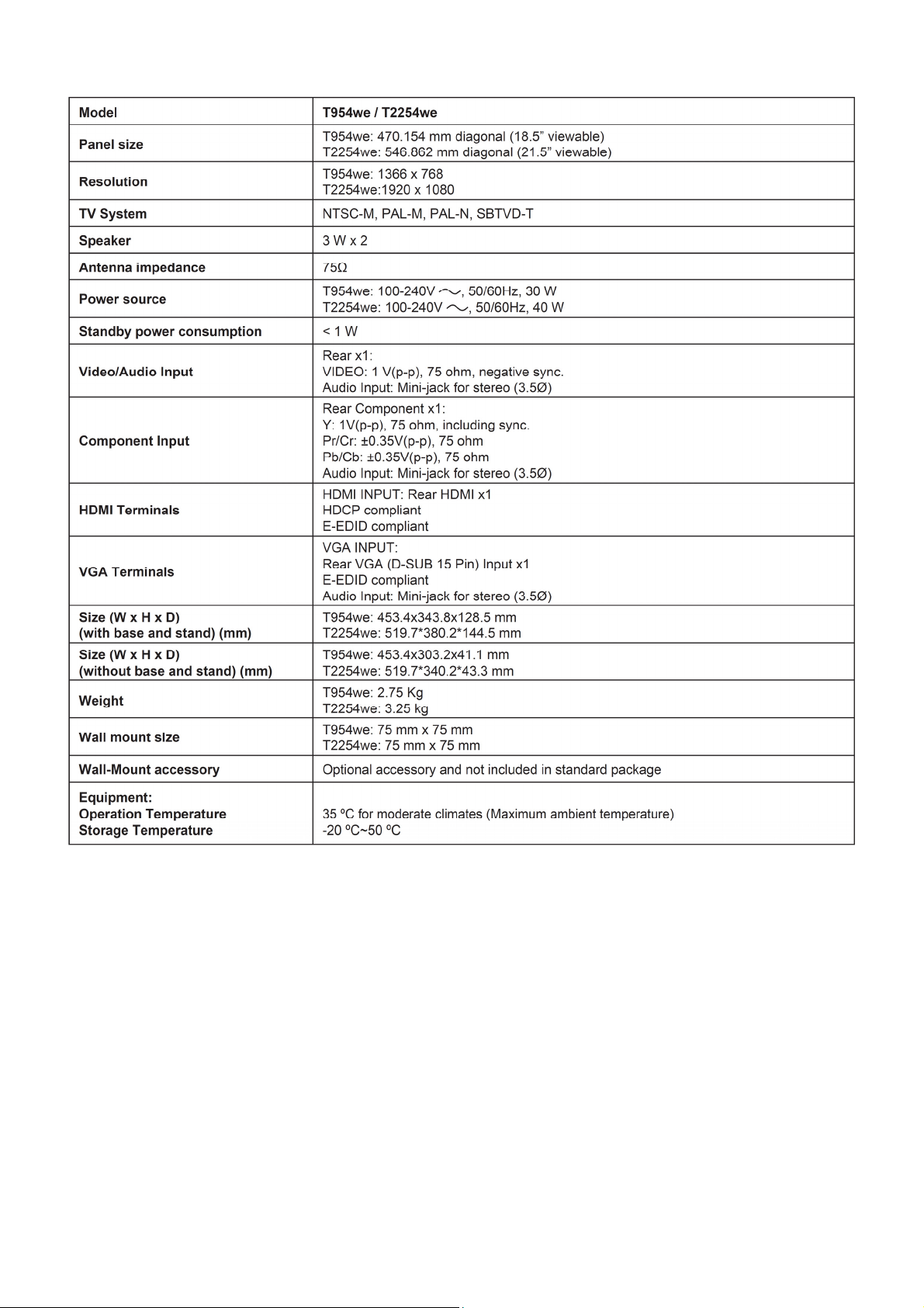
1. General Specification
Note:
• Designs and specifications are subject to change without notice.
• This model may not be compatible with features and/or specifications that may be added in the future.
4
Page 5
2. Operating Instructions
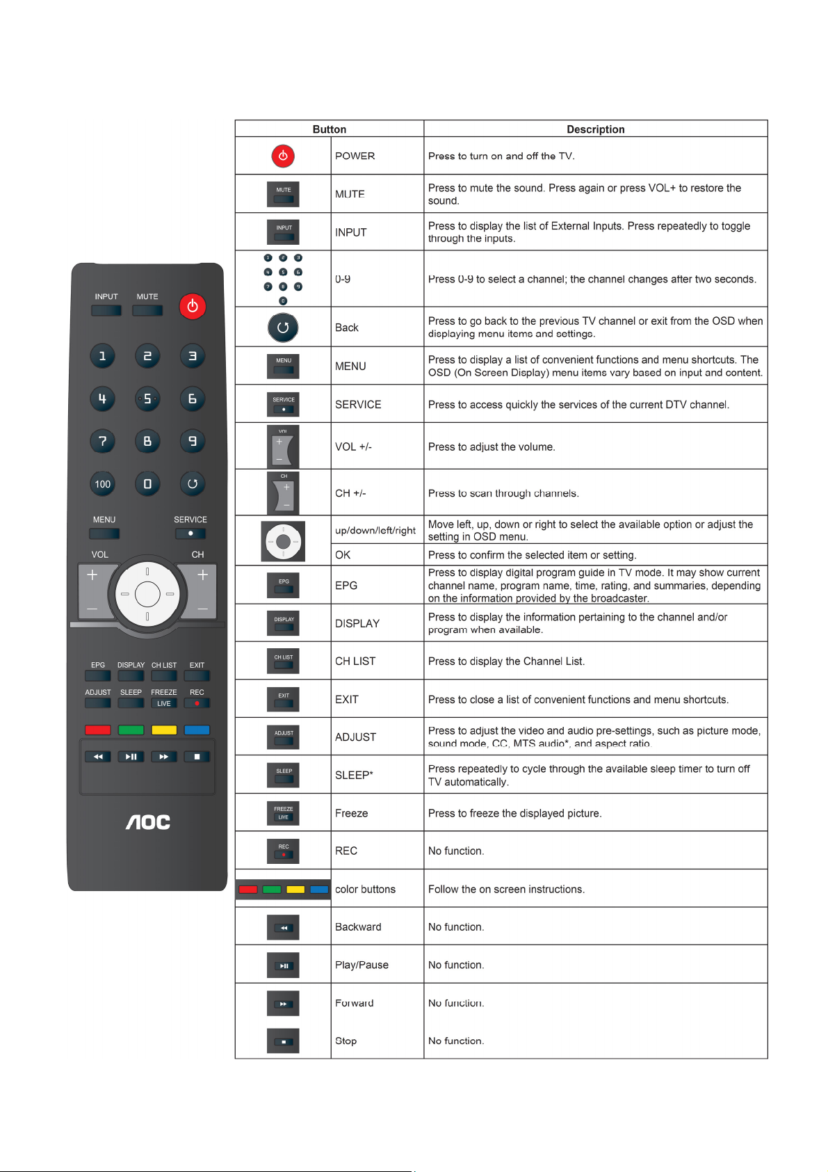
2.1 The Use of Remote Control
5
Page 6
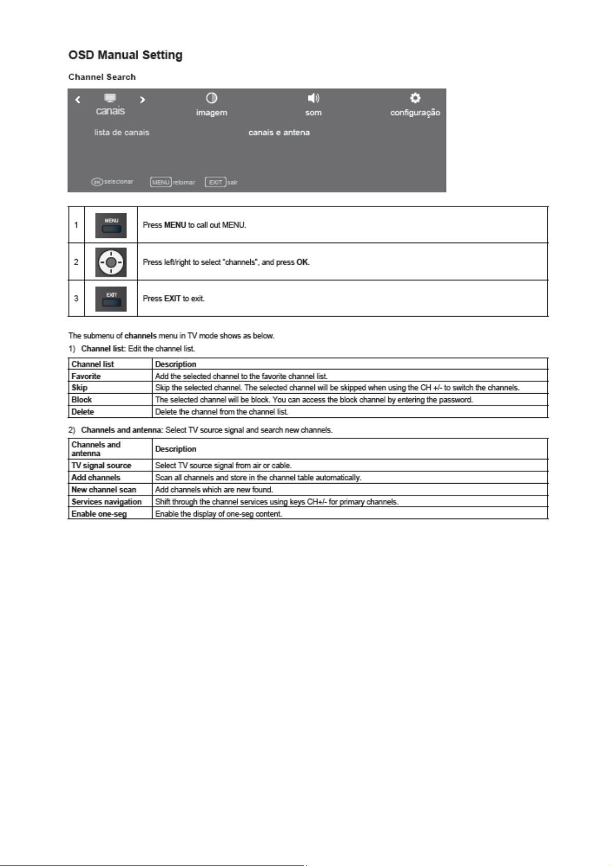
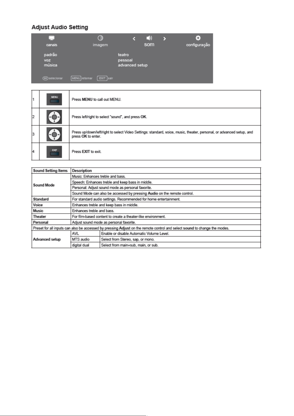
2.2 To Use the Menus
6
Page 7
7
Page 8
8
Page 9
9
Page 10
10
Page 11
11
Page 12
12
Page 13
13
Page 14
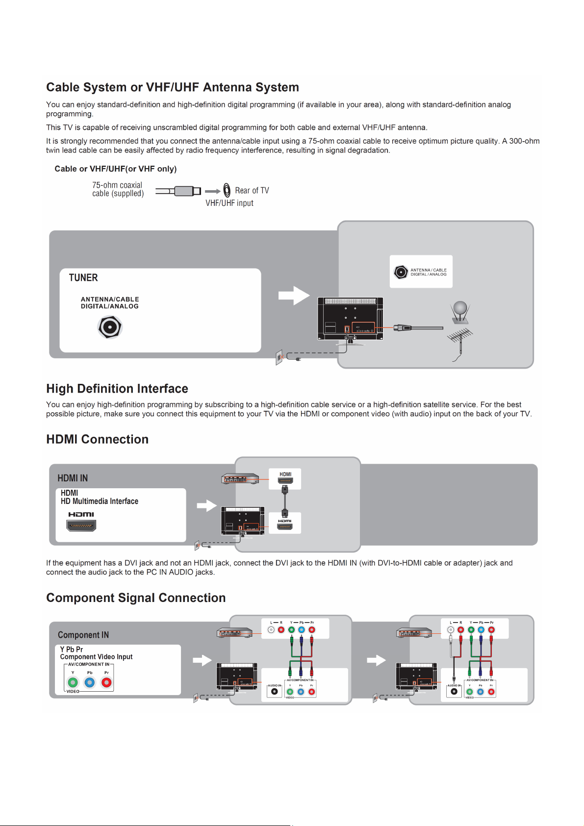
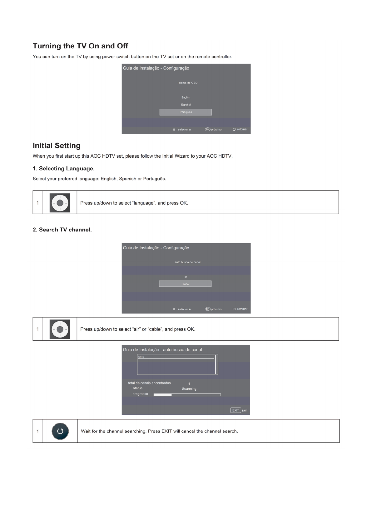
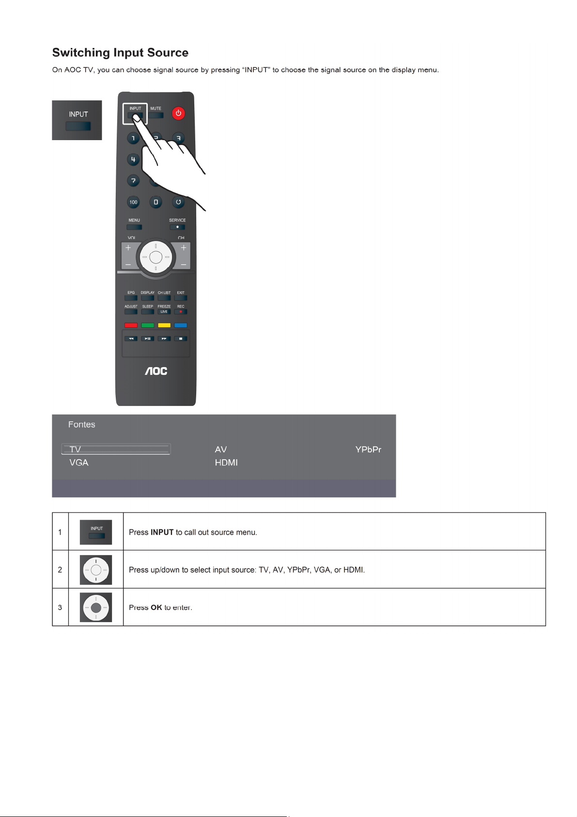
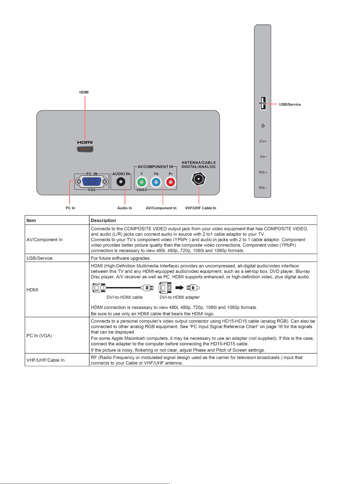
2.3 How to Connect
Connecting TV
14
Page 15
15
Page 16
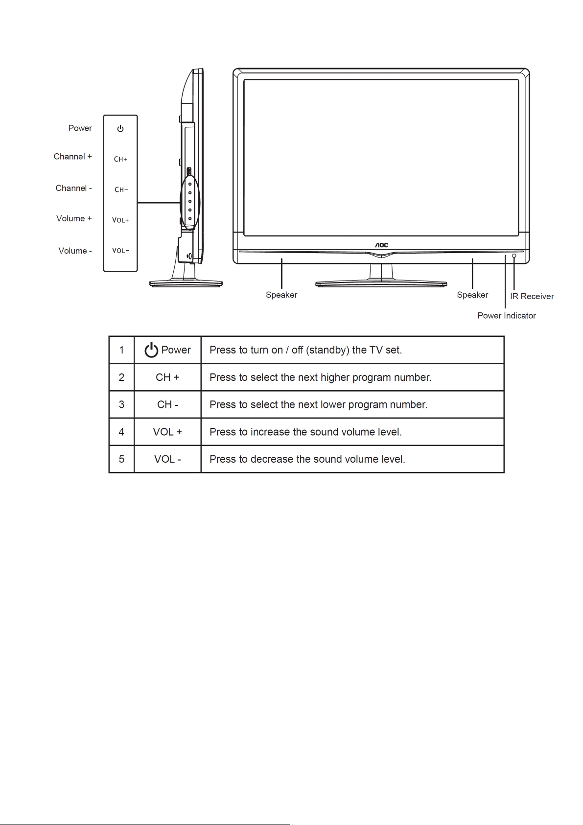
2.4 Front Panel Control Knobs
16
Page 17
17
Page 18
3. Input / Output Specification
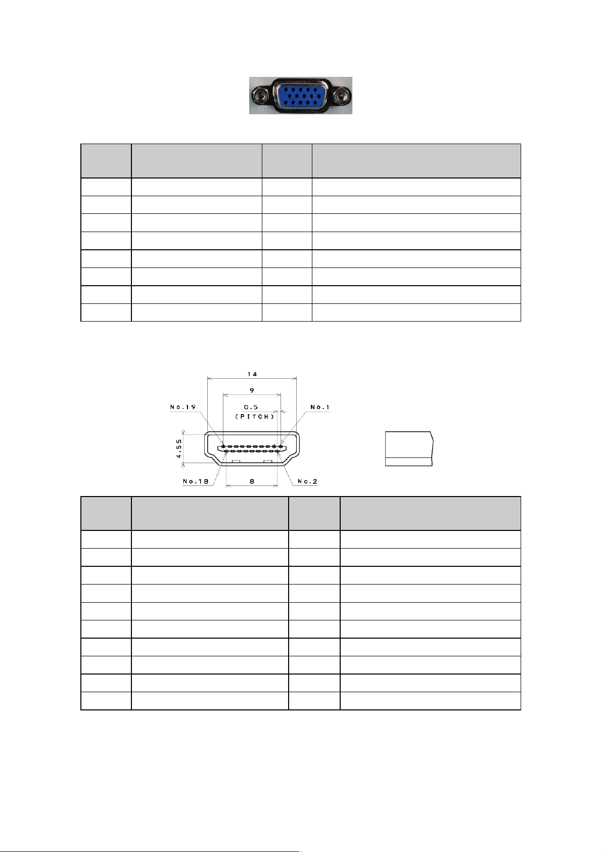
3.1 RGB Signal Input
15 - Pin Color Display Signal Cable
Pin No. Description Pin No. Description
1 Red Video 9 No Pin!
2 Green Video 10 Sync Ground
3 Blue Video 11 RXD
4 TXD 12 Serial Data for DDC
5 Ground 13 H-Sync.
6 Red Ground 14 V-Sync.
7 Green Ground 15 Serial Clock for DDC
8 Blue Ground
3.2 HDMI Digital Connector Pin Assignments
Pin No. Description Pin No. Description
1 TMDS Data2+ 2 TMDS Data2 Shield
3 TMDS Data2- 4 TMDS Data1+
5 TMDS Data1 Shield 6 TMDS Data1-
7 TMDS Data0+ 8 TMDS Data0 Shield
9 TMDS Data0- 10 TMDS Clock+
11 TMDS Clock Shield 12 TMDS Clock13 CEC 14 NC
15 SCL 16 SDA
17 DDC/CEC Ground 18 +5V Power
19 Hot Plug Detect
18
Page 19
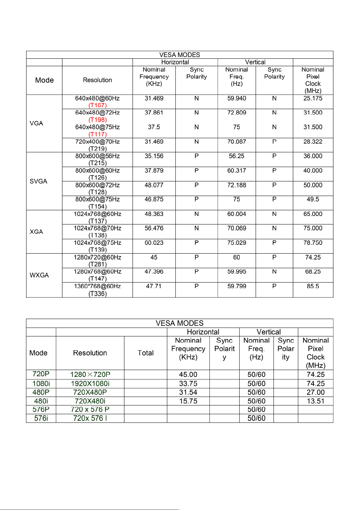
3.3 Compatible Mode Table
Analog RGB Input Signal Timing
HDMI Input Signal Timing
19
Page 20
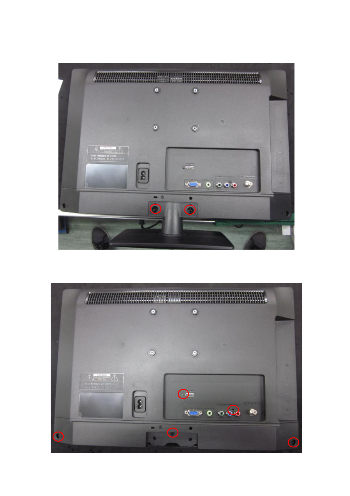
4. Mechanical Instructions
T954we
1. Remove the screws to remove STAND and BASE.
2. Remove the screws to remove REAR COVER.
20
Page 21
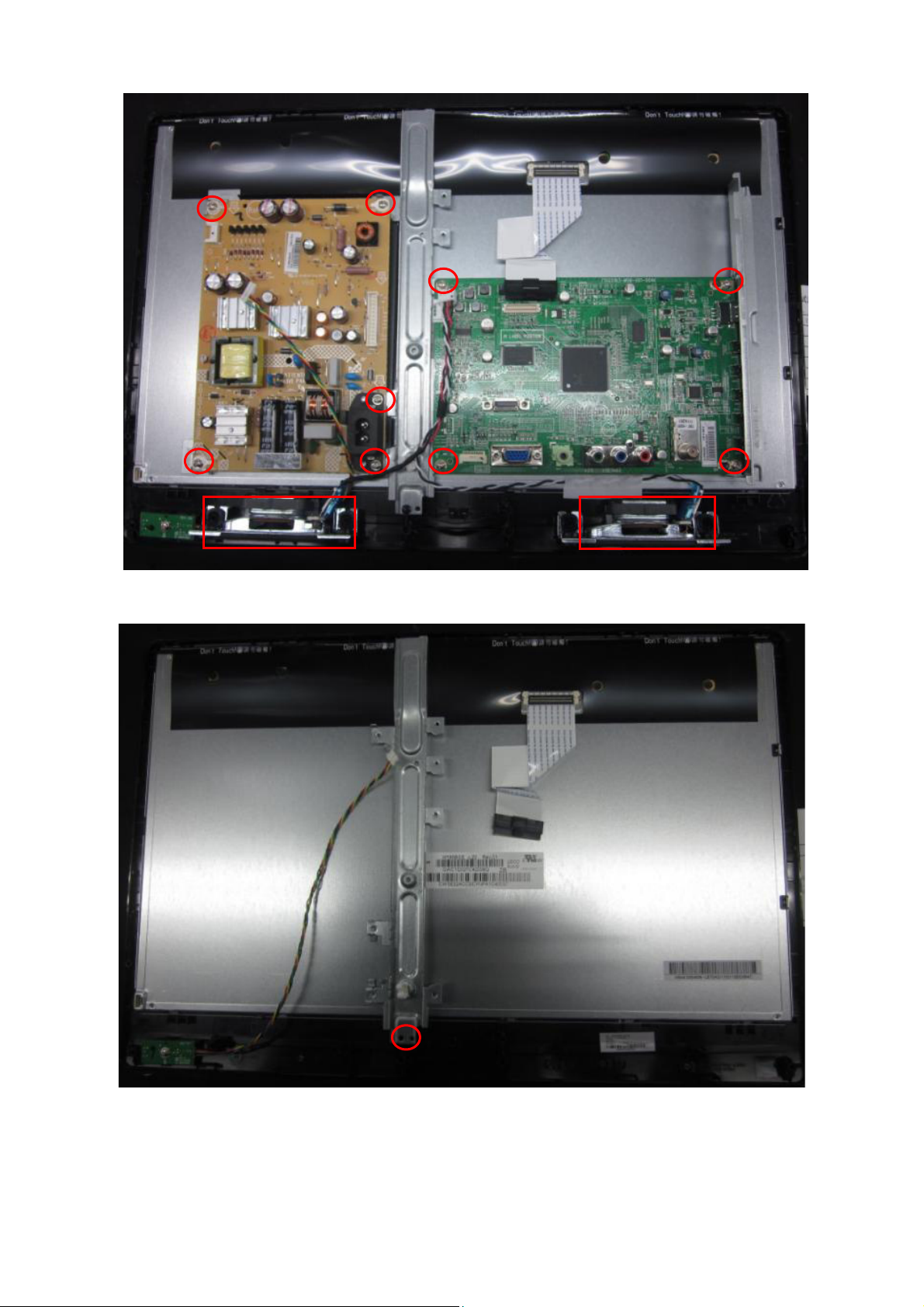
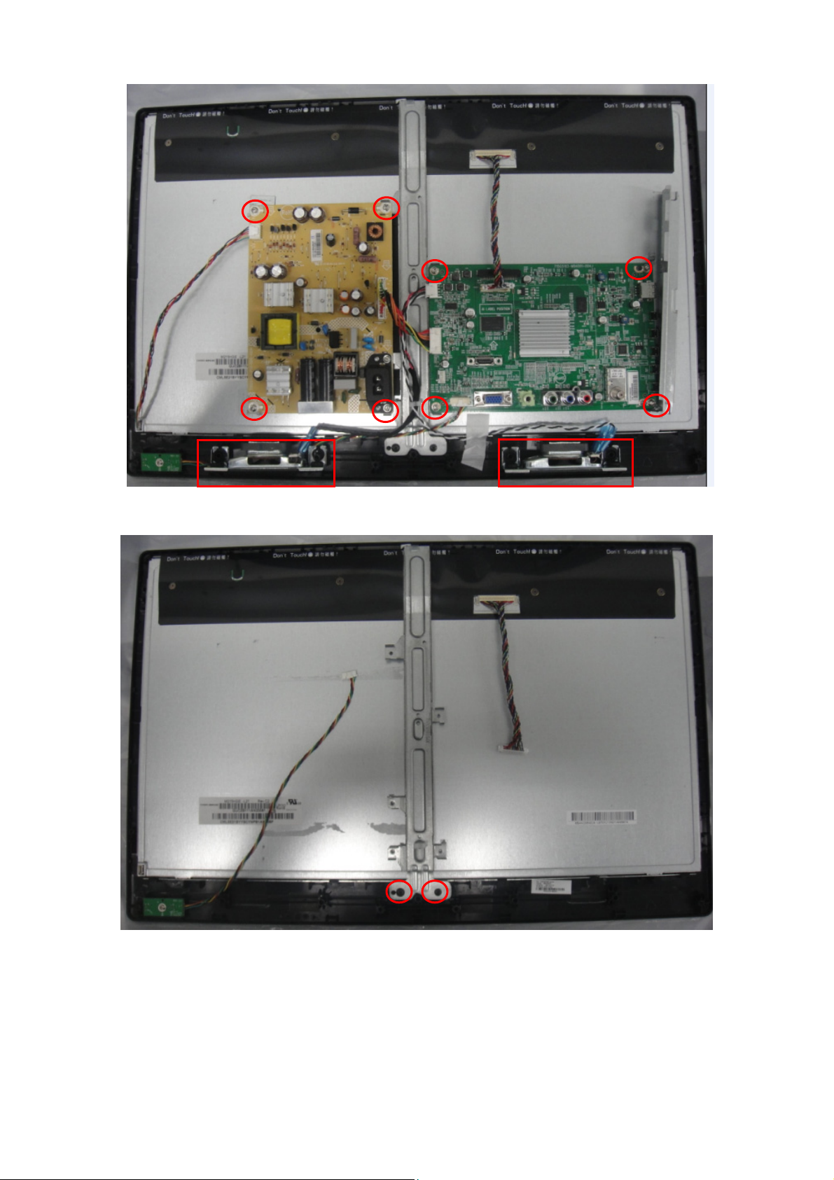
3. Remove the screws to remove SPEAKERS, MAIN BOARD and POWER BOARD.
4. Remove the screw to remove the BKT and separate the Panel and Bezel.
21
Page 22
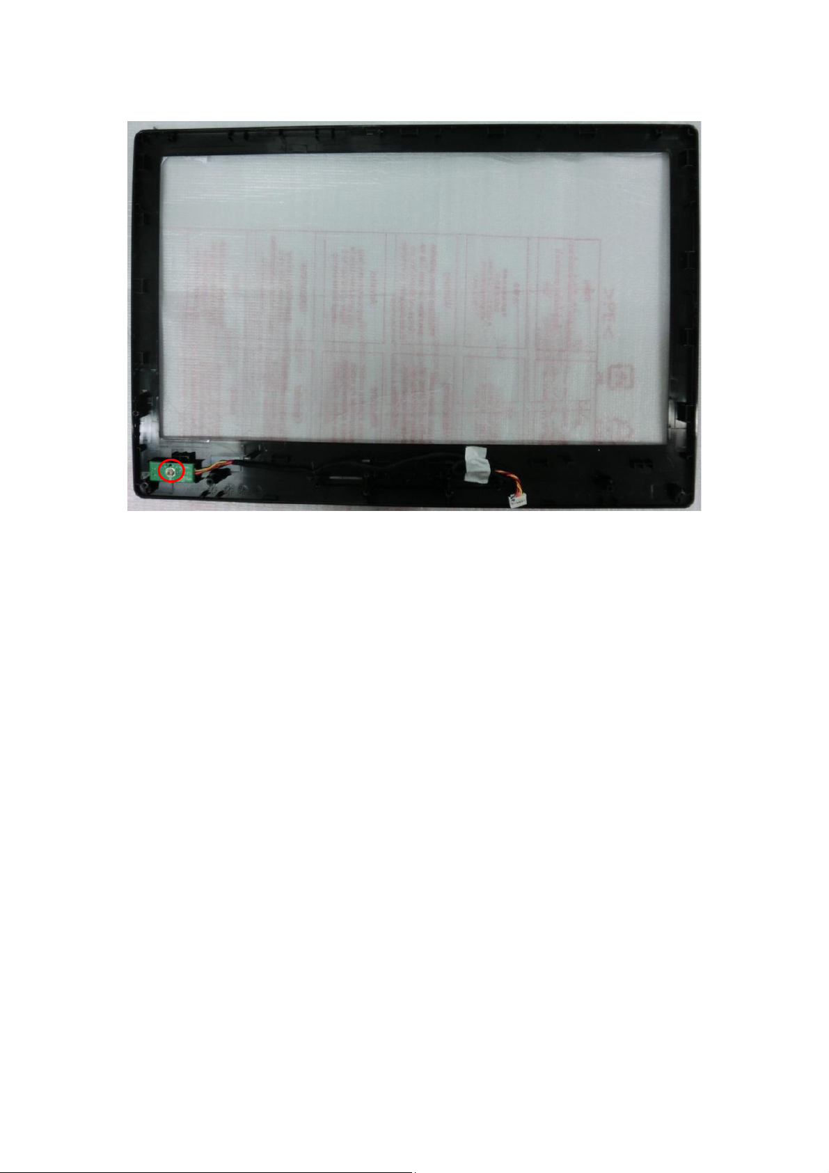
5. Remove the screw to remove IR BOARD.
22
Page 23
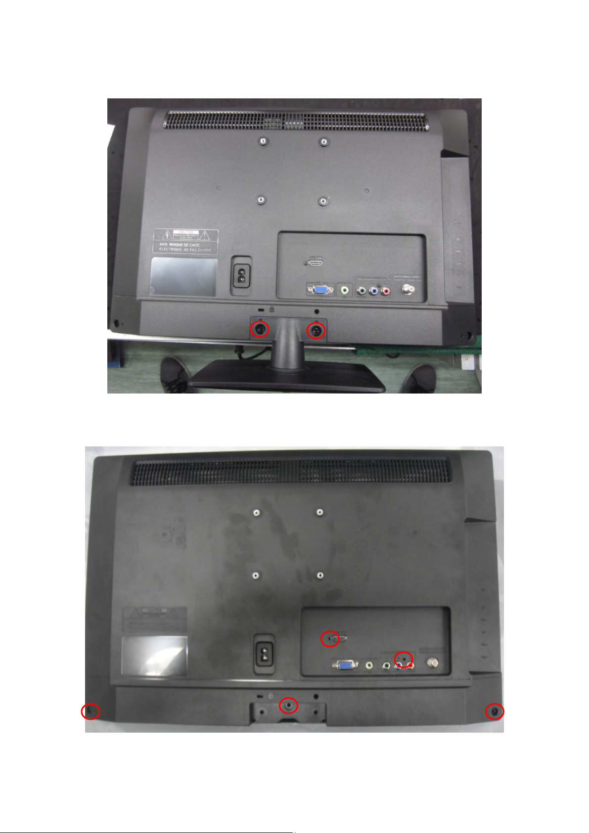
T2254we
1. Remove the screws to remove STAND and BASE.
2. Remove the screws to remove REAR COVER.
23
Page 24
3. Remove the screws to remove SPEAKERS, MAIN BOARD and POWER BOARD.
4. Remove the screws to remove the BKT and separate the Panel and Bezel.
24
Page 25

5. Remove the screw to remove IR BOARD.
25
Page 26
p
p
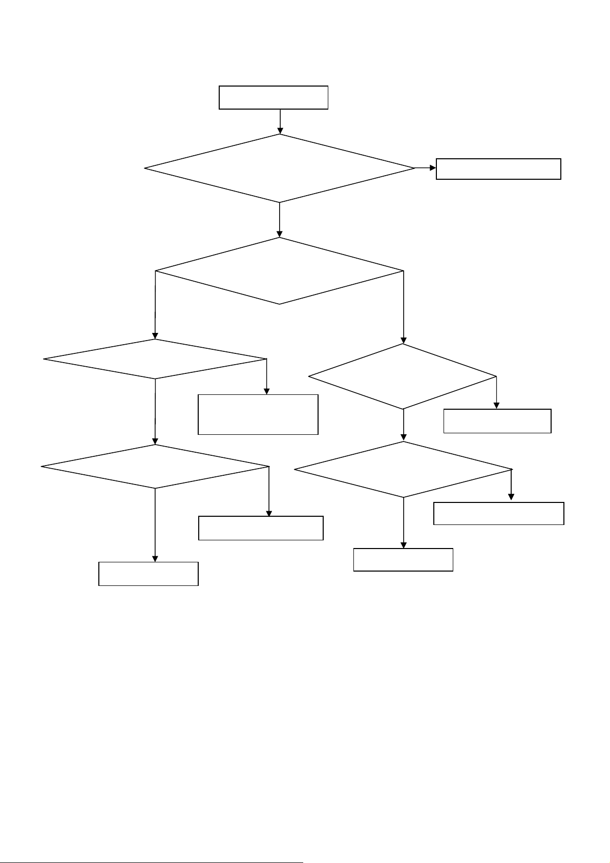
5. Repair Flow Chart
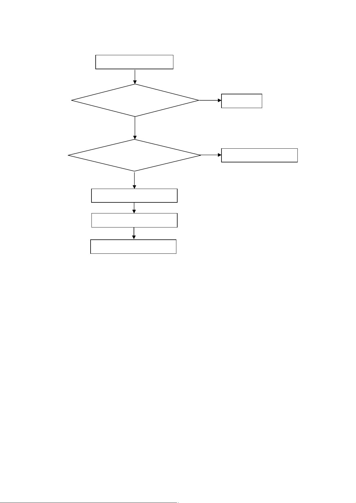
1. No power
No power (LED “Off”)
Check the AC input and
the
ower is “ON”?
Yes
Power board
out
ut=5.2V?
Yes
Check the IR board and LED
Replace the IR board
No
Replace the main board
No
Power “On”
No
Replace the power board
26
Page 27
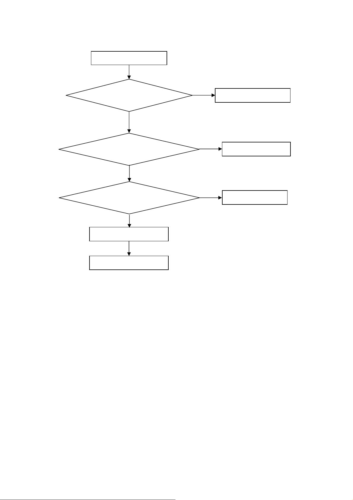
2. Can’t start
Can’t start (LED red)
Power board output=16V?
Yes
Check the power key is under control?
No
Check the IR receiver is normal?
No
Replace the power board
Yes
Replace the key board
Yes
Replace the IR board
No
Replace the main board
No
Replace the Power board
27
Page 28
3. Abnormal display
Abnormal Display
Check the source
Yes
Enter factory mode to do
“EEPROM initial”&“Reset”
No
No
Reset the source
Check the main board
Yes
Check the LVDS cable
Yes
Check the panel
No
Replace the panel
No
Replace the main board
No
Replace the LVDS cable
28
Page 29
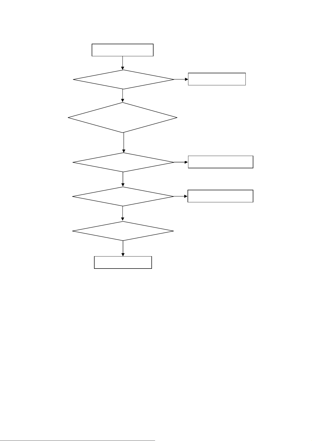
4. No display
No display (No LED)
Check TV is under control and power
on/off by remote control and power key?
Yes
Check the LVDS cable
Yes
Yes
Check the backlight is
“On”?
No
Reinsert or replace the
LVDS cable
No
No
Check the B/L
signal is available?
Yes
Replace the main board
No
Replace main board
Panel Vcc = 3.3V?
Yes
Replace the Panel
No
Replace the main board
Power board output=16V?
Yes
Replace the Panel
Replace the power board
No
29
Page 30

5. Sound problem
No sound or sound abnormal
Check the audio source connection
and the TV system are correct?
Yes
Check the TV is muted, adjust the
volume or enter the menu to reset?
No
No
Reinsert the audio cable or
change the TV system
Enter factory mode to do “Reset”
No
Check the cable between the
speakers and main board is OK?
Yes
Check the speaker resistance value is in spec
(Remark: The value is marked on the speaker)?
Yes
Replace the cable
Replace the main board
No
No
Replace the speaker
30
Page 31

6. Remote control malfunction
Remote Control malfunction
Check the remote control battery is
not properly placed or no power?
No
Use the other remote controls
No
Whether the IR board is
abnormal?
No
Replace the main board
Yes
Replace the battery
Yes
Replace the remote control
Yes
Replace the IR board
31
Page 32

7. OSD is unstable or can’t work normally
OSD is unstable or can’t work normally
Key board connected properly?
Yes
Buttons are OK?
Yes
Key board is OK?
Yes
Enter factory mode to do “Reset”
No
No
No
No
Reconnect the key board
Replace the button function
Replace the key board
Replace the main board
32
Page 33

6. PCB Layout
6.1 Main Board
715G5183M01001004K
33
Page 34

34
Page 35

6.2 Power Board
715G5147P01000001H
35
Page 36

6.3 IR Board
715G5061R02002004M
36
Page 37

7. Adjustment
ADC Adjustment
1. Factory Mode
Turn on the TV. Press menu key and then press number key 1+9 +9+9+back. It will achieve the factory mode.
2. ADC Adjustment
(1) Change TV, press the “Current Source” to Component mode and change signal to TIMING 311and 314), Pattern
185(Color BAR), press the “Auto Color”;
(2) Change TV, press the “Current Source” to PC mode and change signal to PC TIMING 137(1024X768); Pattern
42(5 MOSAIC), press the “Auto Color”.
3. White Balance Adjustment
(1)Enter into the factory mode:(same as the above-mentioned).
(2)Take an example of adjust Ypbpr source.
a. Select item ”Source”: Ypbpr and item “Color Temp”: Normal, Adjust gain of RGB to meet spec in the below
setting of Tim\pat. (COMPONENT mode: TIM = 314; PAT = 141(80IRE))
b. Select item ”Source”: Ypbpr and item “Color Temp”:Warm, Adjust gain of RGB to meet spec in the below setting
of Tim\pat. (COMPONENT mode: TIM = 314; PAT = 141(80IRE))
c. Select item “Source”: Ypbpr and item “Color Temp”: Cool, Adjust gain of RGB to meet spec in the below setting
of Tim\pat. (COMPONENT mode: TIM = 314; PAT = 141(80IRE))
(3) Take an example of adjust VGA Normal:
a. Select item “Source”: VGA and item “Color Temp”: Normal, Adjust gain of RGB to meet spec in the below setting
of Tim\pat. (VGA mode: TIM = 137; PAT = 141(80IRE)
b. Select item “Source”: VGA and item “Color Temp”: Warm, Adjust gain of RGB to meet spec in the below setting
of Tim\pat. (VGA mode: TIM = 137; PAT = 141(80IRE)
c. Select item “Source”: VGA and item “Color Temp”: Cool, Adjust gain of RGB to meet spec in the below setting of
Tim\pat. (VGA mode: TIM = 137; PAT = 141(80IRE)
4、The following color specifications for reference, to RD engineering specifications.
Source VGA/YPbPr VGA/YPbPr VGA/YPbPr
Temp Normal/(7500 K) Warm/(6500 K) Cool/(9300 K)
x (center) 0.295 0.020 0.313 0.020 0.285 0.020
y (center) 0.305 0.020 0.329 0.020 0.293 0.020
Note: all models of color temperature within specification, but also ensure the brightness conform to engineering
specifications.
37
Page 38

8. Block Diagram
DDR II X 1
64Mx16b / 1066 MHz
NAND FLASH
16MB
A RF
TUNER (Silicon in CAM)
PC IN
CVBS
R/L IN
HDMI1
HDMI2
DDC
DDC
24C02
24C02
DDC
DTV
DEMOD
24C02
Series TS
Analog IF+/-
RGB
CV BS
DDC
DDC
ATV
DEMOD
RTD2684
LCD PANEL
LVDS (50/60 Hz)
CVBS Out
Digital Audio Output(COIXIAL)
L/R
SPDIF
HeadPhone Out
AUD IO AMP
TI 3113
SPK
USB1
2.0
UARTKEY RC
38
Page 39

PWR_16V
FB103
PWR_5V
FB101
509.3mA
FB726
734.5 mA
FB107
BUCK (3A)
AT1529F11U
U108
BUCK (3A)
AT1529F11U
U106
VCC33_STB
656mA
L704
Power_EN
143mA
513mA
MOS SW
Q4010
AO4421
FB114
FB115
270mA
FB116
70mA
DVDD3V3
143mA
LDO
G912T63U
U106
D_5V
515mA
LDO
G1084-ADJ
U101
FB113
ALWAYS ON
FB111
FB4017
D1V8
D1V8
FB4016
30mA
280mA
180mA
90mA
70mA
2260mA
230mA
285mA
DM3V3
A3V3
ST_D1V2
A1V2
IO_3.3V
CORE_1.2V
DDR_1.8V
U401
RTD2684D
Main chip
NAND FLASH
HY27UF081G2A-TPCB
U403
DDR2
NT5TU64M16GG-BD
64Mx16-1066MHz
U402
+16V
Power_EN
1104.5 mA
1400mA for 21.5 CMO Panel
600mA for 18.5 CMO Panel
5VSB
FB904
FB905
MOS SW
Q103
AO4421
+16V
D_5V
D_5V
294.1mA
800mA
600mA
AUDIO_VDD
D3V3
370mA
LVDS_PWR_EN
Audio Amp
TPA3113D2
U901
AO4412
Q1001
LDO
G903T63
U4007
LVDSVDDMOS SW
DVDD3V3
DVDD3V3
DVDD3V3
LDO
G912T63UF
U107
370mA
TH1001
LVDS Connect
CN408 (40P)
800mA
FB1109
FB1107
L1108
USB5V
D1V2
138mA
DVDD3V3
5mA
3.3V_TUNER
U1101
TC90527
ISDBT
Demod
TUNER
TU701
Tuner
USB
USB Connect
CN103
+5V real comsumption 2.15A (185 CMO panel) from HDMI black pattern
+5V real comsumption 2.95A (215 CMO panel)from HDMI black pattern
39
Page 40

9. Schematic Diagram
9.1 Main Board
715G5183M01001004K
DC POWER INPUT form PSU
CN700
1
2
3
4
5
6
7
8
9
10
CONN
BL_PWM:
Normal:Max :+3V3, Mi n:0V
Stand_By :0V
BL_ON1:
Normal: High
Stand_B y:
Low
C120
100N 16V
C0402
DGND
C128
100N 16V
C0402
DGND
DGND
DGND DGND
DGND
PWR_5V
R123
10R
R0402
U105
E-PAD
1
VCC
VIN
2
REF
LX
3
GND
PGND
FB4EN
AT1529F11U
56A379-92
DGND
Vout = 0.8x(1+R1/R2)
=1.36
Main chip I/O Power 3.3V
C4174
100N 16V
C0402
C4179
100N 16V
C0402
R4370
10R
R0402
U108
E-PAD
1
VCC
2
REF
3
GND
PGND
FB4EN
AT1529F11U
56A379-92
Vout = 0.8x(1+R1/R2)
=3.32V
BL_ON1_PWR
BL_PWM_PWR
9
8
7
6
5
9
8
VIN
7
LX
6
5
FB101
120R/6000mA
L0805
1 2
R124
10K
R0402
DGND
DGND
PWR_16V
22UF 16V
2.2uH 30%
L101
C0402
R4371
10K
R0402
PWR_ON
22UF 16V
C122
C132
NC
C4176
2.2uH 30%
L2908
C4185
NC
C0402
C104
22UF 16V
C102
100NF 25V
D5V_STB DGND
DGND DGND
FB107
120R/6000mA
L0805
1 2
C123
100N 16V
C0402
DGND
R1
R127
33K 1%
R0402
R2
R130
47K +-1% 1/16W
R0402
DGND
DGND
R1
R4372
34.8K 1/16W 1%
R0402
C4181 100N 16V
R4373
1.02K 1%
R0402
R4374
10K 1%
R2
R0402
DGND
FB103
120R/6000mA
L0805
1 2
D5V_STB
R102
1K
R0402
C105
100N 16V
C0402
FB4038
120R/6000mA
1 2
C4177
100N 16V
C0402
C4211
22UF 16V
C0402
C4207
10UF 25V
C1210
DGND
R4387
NC
R0603
R104
Q102
PMBS3904
1K 1/16W 5%
R0402
SOT23BEC
C4205
+
220UF 16V
EC63
SMD
6.3 X7.7
DGND
D_5V
Core Power(D1V3)
C133
100N 16V
C0402
DGND
D5V_STB
L0805
VCC33_STB
C4212
22UF 16V
DGND
+16V
C109
0.1UF50V
DGND
POWER_BD_Turn_ON 6
C4209
22UF 16V
DGND
FB114
1 2
120R/3000mA
L0603
FB115
1 2
120R/3000mA
L0603
FB116
1 2
120R/3000mA
L0603
C4210
22UF 16V
POWER_BD_Turn_ON6
BL_ON1_PWR13
BL_PWM_PWR13
D5V_STB & D_5V switch
D5V_STB
R710
10K 1/10W
R0603
R107
47K +-5% 1/ 10W
DGND
R0603
Q104
PMBS3904
SOT23BEC
NC/10K
R110
10K
R109
DGND
POWER_EN
POWER_EN6
Main chip Power(ST_D1V2,A1V2)
U106
P01_POWER
C135
100N 16V
C0402
D_5V
G912T63U
SOT223GOI
VI3VO
D2903
GS1A
C110
10uF 10V
C0805
2
4
4
R125
GND
NC
R0603
1
R128
0R05 1/10W
R0603
DGND DGND
DDR Power 1.8V
TO-252
AP1084D18G-13
VIN3VOUT
C111
100N 16V
C0402
Demod 1.2V
U107
G912T63U
DVDD3V3
SOT223GOI
C138
1uF 10V
OEM MODEL
TPV MODEL
PCB NAME
U101
1
VI3VO
1
Sheet
C131
22UF
C0805
C136
100N 16V
C0402
2
R118
NC/3.3K 1%
GND/ADJ
R0402
R2
2
4
4
GND
DGND
715G5183-M0B-001-0040
of
414Monday, J anuary 30, 2012
D3V3
C130
10uF 10V
C0805
D1V3
DGND
DM3V3
A3V3
D3V3
POWER_EN
POWER_EN6
NC/10K
R4381
Tuner 3.3V
VCC33_STB & DV DD3V3 switch
VCC33_STB
R4375
10K 1/10W
R0603
R4380
10K
DGND
DVDD3V3
1109 new add
FB4046
1 2
NC/120R/3000mA
L0603
D_5V
FB4045
220R/2000mA
1 2
U4007
G903T63UF
2
VIN3VOUT
GND14
C4216
1uF 10V
4
DGND DGND DGND
R4377
10K 1/10W 5%
R0603
Q706
PMBS3904
SOT23BEC
DGND
0926 new add
Q4010
1
D
D
2
D
D
3
D
D
G4S
AON4421
DFN8-L3W 2-0_65
0.1UF50V
DVDD3V3
8
7
6
5
C4184
C4188
100N 16V
C0402
3.3V_TUNER
R4378
100K 1/10W
R0603
C4217
22UF 16V
DGND
DGND
DVDD3V3
R4423
NC/0R051/8W
VCC33_STB
T P V ( Top Victory Electronics Co . , Ltd. )
A
絬隔瓜絪腹
Key Component
Date
D_5V
Q103
1
8
D
D
2
7
D
D
3
6
D
D
5
G4S
AON4421
DFN8-L3W 2-0_65
C103
0.1UF50V
C0603
FB111
1 2
120R/3000mA
L0603
R1
R116
0R05 1/16W
R0402
DGND DGNDDGND
Vout=1.8V fixed
DV12
C139
22UF
C0805
DGNDDGND
C113
100N 16V
C0402
C4187
100N 16V
C0402
C4186
100N 16V
C0402
A1V2
ST_D1V2
R112
100K 1/10W
R0603
D1V8
SMD
6.3 X7.7
+
Size
Rev
称爹
DGND
D5V_STB
C112
100UF 16V
EC63
C
<>
称爹
40
Page 41

From RTD268x
S_DQ_IN0
S_DQ_IN1
S_DQ_IN2
S_DQ_IN3
S_DQ_IN4
S_DQ_IN5
S_DQ_IN6
S_DQ_IN7
S_DQ_IN8
S_DQ_IN9
S_DQ_IN10
S_DQ_IN11
S_DQ_IN12
S_DQ_IN13
S_DQ_IN14
S_DQ_IN15
S_DA_IN [0:13]
S_DA_IN0
S_DA_IN1
S_DA_IN2
S_DA_IN3
S_DA_IN4
S_DA_IN5
S_DA_IN6
S_DA_IN7
S_DA_IN8
S_DA_IN9
S_DA_IN10
S_DA_IN11
S_DA_IN12
S_DA_IN13
S_LUDQS#_ IN6
S_LUDQS_IN6
S_LLDQS#_I N6
S_LLDQS_IN6
S_DODT_IN6
S_WE#_IN6
S_CAS#_IN6
S_RAS#_IN6
S_CKE_IN6
S_CK_IN6
S_CK#_IN6
S_DBA0_IN6
S_DBA1_IN6
S_DM0_IN6
S_DM1_IN6
S_DBA2_IN6
S_DQ_IN[ 0:15] 6
S_DA_IN[0:13] 6
S_LUDQS#_I N
S_LUD QS_IN
S_LLDQS#_I N
S_LLDQS_I N
S_DOD T_IN
S_WE#_IN
S_CAS#_I N
S_RAS#_I N
S_CKE_IN
S_CK_I N
S_CK#_I N
S_DBA0_I N
S_DBA1_I N
S_DM0_IN
S_DM1_IN
S_DBA2_I N
S_DQ_IN14
S_DM1_IN
S_DQ_IN9
S_DQ_IN11
S_DQ_IN12
S_DQ_IN6
S_DM0_IN
S_DQ_IN1
S_DQ_IN4
S_DQ_IN3
S_LLDQS_I N
S_LLDQS#_I N
S_LUDQS_I N
S_LUD QS#_IN
S_DQ_IN15
S_DQ_IN8
S_DQ_IN10
S_DQ_IN13
S_DQ_IN7
S_DQ_IN0
S_DQ_IN 2
S_DQ_IN 5
S_CK_IN
S_CK#_IN
S_RAS#_IN
S_CAS#_IN
S_DA_IN 0
S_DA_IN 2
S_DA_IN 4
S_DA_IN 6
S_DA_IN 8
S_DA_IN 11
RP4000 22oHM 1/16W
1
8
CA0402
2
7
3
6
4
5
RP400122oHM 1/16W
1
8
CA0402
2
7
3
6
4
5
RP400222oHM 1/16W
1
8
CA0402
2
7
3
6
4
5
RP400322oHM 1/16W
1
8
CA0402
2
7
3
6
4
5
RP400422oHM 1/16W
1
8
CA0402
2
7
3
6
4
5
R4035
R4037
R4036
R4038
close RTD268x
R4040
8
7
6
5
8
7
6
5
RP4005
RP4006
100R 1/16W 5%
R0402
1
2
3
4
1
2
3
4
close DDR
51R
CA0402
51R
CA0402
S_DQ14
S_DM1
S_DQ9
S_DQ11
S_DQ12
S_DQ6
S_DM0
S_DQ1
S_DQ4
S_DQ3
S_LLDQS
S_LLDQS#
S_LUDQS
S_LUDQS#
S_DQ15
S_DQ8
S_DQ10
S_DQ13
S_DQ7
S_DQ0
S_DQ2
S_DQ5
S_CK
S_CK#
R0402
R0402
R0402
R0402
S_CK#S_CK
S_RAS#
S_CAS#
S_DA0
S_DA2
S_DA4
S_DA6
S_DA8
S_DA11
22R 1/16W 5%
22R 1/16W 5%
22R 1/16W 5%
22R 1/16W 5%
R4034
1K 1/16W
R0402
DGND
S_DODT_IN
1V8DDR
M9
S_DA0
M8
S_DA1
M3
S_DA2
M7
S_DA3
N2
S_DA4
N8
S_DA5
N3
S_DA6
N7
S_DA7 S_DQ5
P2
S_DA8
P8
S_DA9
P3
S_DA10
M2
S_DA11
P7
S_DA12
R2
S_DA13
R8
R3
R7
S_DBA0
S_DBA1
S_DBA2
S_DM0
S_DM1
S_RAS#
S_CAS#
S_WE#
S_CK
S_CK#
S_CKE
R4033
22R 1/16W 5%
R0402
L2
L3
L1
F3
B3
K7
L7
K3
L8
J8
K8
K2
K9
VDD1A1VDD2E1VDD3R1VDD4J9VDD5
A0
A1
A2
A3
A4
A5
A6
A7
A8
A9
A10/AP
A11
A12
NC5
NC3
NC4
1Gb DDR II SDRAM
BA0
BA1
BA2
LDM
UDM
RAS#
CAS#
WE#
CS#
CK
CK#
CKE
ODT
VSS1N1VSS2A3VSS3E3VSS4J3VSS5
P9
VDDQ 1C1VDDQ 2G1VDDQ 3C3VDDQ 4G3VDDQ 5C7VDDQ 6G7VDDQ 7A9VDDQ 8C9VDDQ 9
VSSQ1B2VSSQ2D2VSSQ3F2VSSQ4H2VSSQ5A7VSSQ6E7VSSQ7B8VSSQ8D8VSSQ9F8VSSQ10
DGND
S_DVREF
J2
VREF
J7
H8
U4002
J1
VDDL
DQ0
DQ1
DQ2
DQ3
DQ4
DQ5
DQ6
DQ7
DQ8
DQ9
DQ10
DQ11
DQ12
DQ13
DQ14
DQ15
LDQS
LDQS#
UDQS
UDQS#
NC1
NC2
VSSDL
H5PS1G63EFR -G7C
PBGA-84-8X13
G8
G2
H7
H3
H1
H9
F1
F9
C8
C2
D7
D3
D1
D9
B1
B9
F7
E8
B7
A8
A2
E2
E9
G9
VDDQ10
S_DQ0
S_DQ1
S_DQ2
S_DQ3
S_DQ4
S_DQ6
S_DQ7
S_DQ8
S_DQ9
S_DQ10
S_DQ11
S_DQ12
S_DQ13
S_DQ14
S_DQ15
S_LLDQS
S_LLDQS#
S_LUDQS
S_LUDQS#
S_DA_IN 13 S_DA13
S_WE#_I N
S_CKE_IN
S_DBA1_I N
S_DBA0_I N
S_DA_IN 1
S_DA_IN 10
S_DA_IN 5
S_DA_IN 3
S_DA_IN 9
S_DA_IN 7
S_DA_IN 12
S_DBA2_I N
R4043
51R 1/16W 5%
R0402
RP4007 51R
1
8
CA0402
2
7
3
6
4
5
RP4008 51R
1
8
CA0402
2
7
3
6
4
5
RP4009 51R
1
8
CA0402
2
7
3
6
4
5
S_WE#
S_CKE
S_DBA1
S_DBA0
S_DA1
S_DA10
S_DA5
S_DA3
S_DA9
S_DA7
S_DA12
S_DBA2
R4041
1K 1/10W 1%
R0603
S_DVREF
R4042
1K 1/10W 1%
R0603
1V8DDR
DGND
C4095
100N 16V
C0402
C4096
100N 16V
C0402
Close to DDR
41
(210mA)
D1V8
FB4027
1 2
120R/3000mA
L0603
T P V ( Top Victory Electronics Co . , Ltd. )
A
絬隔瓜絪腹
Key Component
Date
P03_DDR2
1V8DDR
C4097
22UF
C0805
C4098
100N 16V
C0402
C4099
100N 16V
C0402
C4100
100N 16V
C0402
OEM MODEL
TPV MOD EL
PCB NAME
Sheet
C4101
C4102
100N 16V
100N 16V
C0402
C0402
715G5183-M0B-001-0040
514Monday , January 30, 2012
of
C4103
100N 16V
C0402
DGND
C4104
100N 16V
C0402
C4105
100N 16V
C0402
C4106
100N 16V
C0402
C4107
100N 16V
C0402
Size
Rev
称爹
C4108
100N 16V
C0402
<>
称爹
B
C4109
100N 16V
C0402
Page 42

From DDR2
S_DQ_IN[0:15]5
S_DA_IN[0:13]5
S_LUDQS#_IN5
S_LUDQS_IN5
S_LLDQS#_IN5
S_LLDQS_IN5
S_DODT_IN5
S_WE#_IN5
S_CAS#_IN5
S_RAS#_IN5
S_CKE_IN5
S_CK_IN5
S_CK#_IN5
S_DBA0_IN5
S_DBA1_IN5
S_DM0_IN5
S_DM1_IN5
S_DBA2_IN5
To SPDIF
To Demod
TP_ERRO R14
DEMOD_REST14
S_DQ_IN0
S_DQ_IN1
S_DQ_IN2
S_DQ_IN3
S_DQ_IN4
S_DQ_IN5
S_DQ_IN6
S_DQ_IN7
S_DQ_IN8
S_DQ_IN9
S_DQ_IN10
S_DQ_IN11
S_DQ_IN12
S_DQ_IN13
S_DQ_IN14
S_DQ_IN15
S_DA_IN0
S_DA_IN1
S_DA_IN2
S_DA_IN3
S_DA_IN4
S_DA_IN5
S_DA_IN6
S_DA_IN7
S_DA_IN8
S_DA_IN9
S_DA_IN10
S_DA_IN11
S_DA_IN12
S_DA_IN13
S_LUDQS#_IN
S_LUDQS_IN
S_LLDQS#_IN
S_LLDQS_IN
S_DODT_IN
S_WE#_IN
S_CAS#_IN
S_RAS#_IN
S_CKE_IN
S_CK_IN
S_CK#_IN
S_DBA0_IN
S_DBA1_IN
S_DM0_IN
S_DM1_IN
S_DBA2_IN
TP_DI TP_DI
TP_DI14
TP_CL K14
TP_VALID
TP_VALID14
TP_SYN C
TP_SY N C14
TP_ERROR
DEMOD_REST
From HDMI
HDMI1_D2+9
HDMI1_D2-9
HDMI1_D1+9
HDMI1_D1-9
HDMI1_D0+9
HDMI1_D0-9
HDMI1_CLK+9
HDMI1_CLK-9
HDMI1_DDC_SCL9
HDMI1_DDC_SDA9
HOTPLUG19
HDMI_CEC9
To Audio Amplifier
Line_Out_R12
Line_Out_L12
AMP_STBY12
NAND FLASH
4.7K 1/16W
WP#
3
DGND
120R/3000mA
120R/3000mA
22R 1/16W 5%
R4061
22R 1/16W 5%
DM3V3
SPI_SCK-N_R E#
N_CE0#
N_CLE
N_ALE
N_WE#
1
2
R4427
3
R0402
DGND
A3V3
R325
R326
R327
R301
R328
R330
R331
R332
R333
R4410
C4126
100N 16V
DGND
CORE_1.2V
C4066
C4061
+
SMD
6.3
100N 16V
100UF 16V
X
7.7mm
DDR_1.8V
C4074
C4075
22UF
C0805
100N 16V
SPI_WP
SPI FLASH
(Reserved)
#add 111120 for SPI (Mars)#
D3V3
TX0
RX0
BL_EN
PANEL_EN
AMP_STBY
POWER_EN
N_RDY
N_CE0#
N_ALE
LEDG
LEDR
R4069
10K
R4070
12Q4007
PMBS3904
SPI_CS#
SPI_DI-N_D ATA6
WP#
A3V3
D1V3
1 2
D1V8
1 2
DM3V3
IO_3.3V
NC/4K7 1/16W 5%
R338
FB310
(1.1A)
FB4016
(760mA)
HDMI1_D2+
HDMI1_D2HDMI1_D1+
HDMI1_D1HDMI1_D0+
HDMI1_D0HDMI1_CLK+
HDMI1_CLK-
HDMI1_DDC_SCL
HDMI1_DDC_SDA
HOTPLUG1
HDMI_CEC
8
9
16
17
18
/CS
DO(IO1)
/HOLD(IO3)
/WP(IO2)
GND4DI(IO0)
NC/W25Q64BVSSIG
4K7 1/16W 5%
4K7 1/16W 5%
4K7 1/16W 5%
4K7 1/16W 5%
4K7 1/16W 5%
4K7 1/16W 5%
4K7 1/16W 5%
4K7 1/16W 5%
4K7 1/16W 5%
4K7 1/16W 5%
C4059
100N 16V
C4076
100N 16V
DM3V3
37
VDD12VDD
RE
CE
CLE
ALE
WE
WP19R/B
VSS
13
36
DGND
U4009
8
VCC
7
6
CLK
5
C4067
C4060
100N 16V
C4077
100N 16V
DGND
From TUNER
IF_P10,14
IF_N10,14
I2C_SCL13,14
I2C_SDA13,14
A_IF_AGC10
IF_CTL10
From CVBS1
From YPBPR1
Y1+7
PB1+7
PR1+7
VIN_Y0-7
To POWER
POWER_EN4
BL_ADJ13
POWER_BD_Turn_ON4
From KeyPad
LSADC011
LSADC111
IRRX11
LEDG11
LEDR11
LightSensor_ADC11
U4003
H27U1G8F2BTR-BC
<Package>
29
I/O0
30
I/O1
31
I/O2
32
I/O3
41
I/O4
42
I/O5
43
I/O6
44
I/O7
7
VSS
DM3V3
C4222
100N 16V
DGND
SPI_HOLD
R4428 22R 1/16W 5%
R4429 22R 1/16W 5%
C4062
100N 16V
100N 16V
DGND
C4078
100N 16V
IF_P
IF_N
I2C_SCL
I2C_SDA
A_IF_AGC
IF_CTL
Y1+
PB1+
PR1+
VIN_Y0-
POWER_EN
BL_ADJ
POWER_BD_Turn_ON
LSADC0
LSADC1
IRRX
LEDG
LEDR
LightSensor_ADC
DM3V3
C4042
1uF 25V
DGND
N_DATA0
N_DATA1
N_DATA2
N_DATA3
N_DATA4
N_DATA5
N_DATA6
N_DATA7
N_RDY
2nd source
056G2233 54 =
4K7 1/16W 5%
R4426
SPI_SCK-N_RE#
SPI_D0-N_DATA7
R0402
R0402
C4068
C4121
2.2UF
100N 16V
C4080
C4079
100N 16V
100N 16V
砏
C4081
100N 16V
From LVDS
TEDP13
TEDN13
TECLKP13
TECLKN13
TECP13
TECN13
TEBP13
TEBN13
TEAP13
TEAN13
TODP13
TODN13
TOCLKP13
TOCLKN13
TOCP13
TOCN13
TOBP13
TOBN13
TOAP13
TOAN13
BL_EN13
PANEL_EN13
From VGA
VGA_R+7
VGA_R-7
VGA_G+7
VGA_G-7
VGA_B+7
VGA_B-7
VGA_VS7
VGA_HS7
VGA_IN_L7
VGA_IN_R7
TX07
RX07
VGA_DDC_SDA7
VGA_DDC_SCL7
C4082
100N 16V
TEDP
TEDN
TECLKP
TECLKN
TECP
TECN
TEBP
TEBN
TEAP
TEAN
(pin share function)
(pin share function)
TODP
TODN
TOCLKP
TOCLKN
TOCP
TOCN
TOBP
TOBN
TOAP
TOAN
BL_EN
PANEL_EN
VGA_R+
VGA_RVGA_G+
VGA_GVGA_B+
VGA_B-
VGA_VS
VGA_HS
VGA_IN_L
VGA_IN_R
TX0
RX0
VGA_DDC_SDA
VGA_DDC_SCL
120R/3000mA
D_5V
TH1001 PTCR
C4191
100N 16V
C0402
C4083
C4084
100N 16V
100N 16V
PLL_GND
FB4007
1 2
DGND
t
1A
12
+
DGND
ST_D1V2
C4046
20pF
1
2
X4000
PLL_GND
27MHz
C4047
3
4
20pF
5X3.2 SMD
EQUAL LENGTH and DIFFERENTIAL
IMPEDANCE 90ohm
USB_5V
USB_DM1
C4125
USB_DP1
C4190
220UF 16V
EC63
100N 16V
SMD
6.3 X 7.7mm
C4055
C4056
(0.5A)
10uF 6.3V
10uF 6.3V
DGND
IO_3.3VD3V3
FB4017
1 2
C4085
C4086
120R/3000mA
(36mA)
100N 16V
100N 16V
DGND
Tuner
1.Analog A_IF_AGC controlled by scaler
2.Digital D_IF_AGC controlled by Demod
3.IF_CTL switch A_IF_AGC & D_IF_AGC
IF_CTL10
1 2
FB4004
1 2
FB4003
IF_N
IF_P
AGND
R4017 0R05 1/10W
XOUT
C4089
100N 16V
XIN
FB4025
1 2
120R/3000mA
---><---|>
---><---|>
A1V2
D5V_STB
DGND
C4122
10U 16V
FB4011
1 2
120R/3000mA
FB4018
1 2
120R/3000mA
R4431
1.8K 1%
DET_Drop
R4432
1.3K 1%
USB5V
ZD303
DGND
R4018
NC
R4071
R4072
0R05 1/16W
0R05 1/16W
C4119
C4118
100N 16V
100N 16V
C4088
C4087
100N 16V
100N 16V
AGND
VGA_IN_R
VGA_IN_L
DGND
2.2UF 16VC4011
2.2UF 16VC4010
2.2UF 16VC4193
2.2UFC4197
U4000
CORE_1.2V
257
256
254
255
2.2UF
C4199
AGND
AMP_STBY12
IF_CTL
VDAC_3.3V
TP2915
120R/3000mA
VDACGND
120R/3000mA
VADCGND
1uF 25VC4051
1uF 25VC4052
VADC_3.3V
XIN
XOUT
PLL_3.3V
CORE_1.2V
R4014
100R 1/16W 5%
R4015
100R 1/16W 5%
IO_3.3V
DEMOD_REST
A_IF_AGC
IO_3.3V
CORE_1.2V
CORE_1.2V
DDR_1.8V
S_DQ_IN14
S_DM1_IN
S_DQ_IN9
S_DQ_IN11
DDR_1.8V
S_DQ_IN12
S_DQ_IN6
S_DM0_IN
S_DQ_IN1
DDR_1.8V
S_DQ_IN4
S_DQ_IN3
S_LLDQS_IN
S_LLDQS#_IN
DDR_1.8V
S_LUDQS_IN
S_LUDQS#_IN
S_DQ_IN15
S_DQ_IN8
DDR_1.8V
S_DQ_IN10
S_DQ_IN13
S_DQ_IN7
S_DQ_IN0
DDR_1.8V
S_DQ_IN2
S_DQ_IN5
CN303
USB CONN
56
78
1234
1
2
3
4
R/A
DGND
8.5mm
MLVG0402
USB 2.0
A Type
A1V2
R4398
C4064
0R05 1/16W
100N 16V
A3V3 A3V3A3V3 A3V3
FB4019
1 2
120R/3000mA
1 2
ZD304
MLVG0402
HDMI_1.2V
DGND
HDMI_3.3V
DGND
C4063
100N 16V
C4090
100N 16V
PLL_GND
I2C_SCL
I2C_SDA
TP_CLKTP_CLK
TP_VALID
TP_SYN C
TP_ERROR
1 2
DGNDDGND
253
EPAD
AIN_5L
AIN_4L
1
AIN_4R
AIN_5R
2
LSADC3
3
LSADC5
4
VDAC3V3
5
AVOUT1
6
TP
AVOUT2
7
VDACGND
8
ADC2XGND
9
IF1N
10
IF1P
11
ADC2X3V3
12
PLLGND
13
XIN
14
XOUT
15
PLL3V3
16
D1V2
17
RF_AGC
18
I2C0_SCL
19
I2C0_SDA
20
GPIO_M3
21
GPIO_M4
22
GPIO_M6
23
GPIO_M5
24
GPIO_M7
25
D3V3
26
GPIO_U5
27
GPIO_R4
28
GPIO_R3
29
EFUSE_D3V3
30
D3V3
31
NC
32
NC
33
NC
34
NC
35
D1V2
36
D1V2
37
DDR18VCC
38
DQ_14
39
DM1
40
DQ_9
41
DQ_11
42
DDR18VCC
43
DQ_12
44
DQ_6
45
DM0
46
DQ_1
47
DDR18VCC
48
DQ_4
49
DQ_3
50
DQS0
51
DQS0_N
52
DDR18VCC
53
DQS1
54
DQS1_N
55
DQ_15
56
DQ_8
57
DDR18VCC
58
DQ_10
59
DQ_13
60
DQ_7
61
DQ_0
62
DDR18VCC
63
DQ_2
64
DQ_5
DVRI65CK66CK#67RAS#68DDR18VCC69CAS#70ADDR071ADDR272DDR18VCC73ADDR474ADDR675ADDR876ADDR1177ADDR1378DDR18VCC79WE#80CKE81BA182BA083DDR12VCC84ADDR185ADDR1086ADDR587ADDR388DDR18VCC89ADDR990ADDR791ADDR1292BA293ODT94USB1V295HSDM_096HSDP_097USB3V398HSDM_199HSDP_1
RTD2684D
S_CK_IN
S_RAS#_IN
S_DVREF_A
S_CK#_IN
DDR_1.8V
Jack Detection Function (place
resistor Near Connector)
USB_1.2V
C4065
C4069
100N 16V
100N 16V
DGND
USB_3.3V
C4073
100N 16V
DGND
BB_3.3V
AGND
AGND
1uF 25VC4003
FB302
120R/3000mA
C4004 0.1UF50V
1 2
C304
1uF 16V
C0603
120R/3000mA
BB1GND
To AMP
To AV_out
VD_3.3V
AGND
AGND
DGND
R4400 0R05 1/16W
Line_Out_R
Line_Out_L
DGND
1 2
2.2UFC4017
2.2UFC4015
2.2UFC4016
248
246
247
AIO_1L
AIO_1R
AOUT_L
S_DA_IN4
S_DA_IN8
S_DA_IN6
1 2
120R/3000mA
FB4013
1 2
FB4020
300R
2.2UFC4194
2.2UFC4195
244
245
AIO_2L
AIO_2R
S_DA_IN13
S_DA_IN11
FB4008
120R/3000mA
HOTPLUG1
2.2UFC4020
2.2UFC4021
FB4001
1uF 25VC4022
47nF 16VC4196
47nF 16VC4202
47nF 16VC4041
BB1GND
VCM_BB
AVDD_BB0
BB1GND
232
237
241
240
239
238
242
235
234
233
236
243
D1V2
VD3V3
AIN_3L
AIN_3R
VIN_14P
VIN_13P
VIN_10P
VCM_BB
BB0_3V3
BB1GND
BB1_3V3
S_DA_IN3
S_CKE_IN
S_DBA1_IN
S_WE#_IN
S_DA_IN10
S_DBA0_IN
S_DA_IN5
S_DA_IN1
USB_3.3V
C345
USB_1.2V
1uF 16V
C0603
AGND
1KOHM +-1% 1/16W
1KOHM +-1% 1/16W
Close to RTD268x IC
C4058
100N 16V
AGND
VD_1.2VA1V2
C4070
2.2UF
AGND
PLL_3.3V
C4091
100N 16V
PLL_GND
DGNDAGND
2.2UFC4200
2.2UFC4198
2.2UFC4201
2.2UFC4014
251
250
249
252
AIN_1L
AIN_1R
AOUT_R
HPOUT_L
HPOUT_R
S_DA_IN2
S_CAS#_IN
S_DA_IN0
A1V2
A3V3
1 2
47nF 16VC4024
47nF 16VC4023
231
230
VIN1N
VIN_12P
S_DA_IN7
S_DA_IN9
R4020
S_DVREF_A
R4021
AVDD_BB0
C4001
close to RTD268x
AGND
VD_1.2V
Y_1.2V
AGND
47nF 16VC4120
47nF 16VC4025
225
229
226
224
228
227
VIN0N
VD1V2
VIN_9P
VIN_11P
VD_GND33
ADC_GND33
S_DODT_IN
S_DA_IN12
S_DBA2_IN
DDR_1.8V
DGND
C4092
4.7UF 10V
AGND
47nF 16VC4029
47nF 16VC4030
223
222
VIN_8P
VIN_7P
YPP1V2
USB_DP1
USB_DM1
1 2
1 2
47nF 16VC4028
221
VIN_Y1N
100
C4053
100N 16V
C4054
100N 16V
FB4014
300R
FB4021
Y1+
PR1+
47nF 16VC4031
47nF 16VC4027
47nF 16VC4032
220
219
218
VIN_6P
VIN_5P
USB1V2
D1V2
101
102
103
120R/3000mA
Y_3.3V
PB1+
VIN_Y0-
VGA_B+
VGA_B-
VGA_G+
VGA_G-
VGA_R+
VGA_R-
47nF 16VC4037
47nF 16VC4038
47nF 16VC4034
47nF 16VC4033
47nF 16VC4040
47nF 16VC4039
47nF 16VC4036
47nF 16VC4035
217
211
216
214
212
210
215
213
VIN_4P
VIN_3P
VIN_2P
VIN_1P
VIN_BN
VIN_RN
VIN_GN
VIN_Y0N
GPIO_R1
GPIO_K3
GPIO_K4
GPIO_K5
GPIO_K6
D3V3
GPIO_K7
GPIO_S6
104
105
106
107
108
109
110
111
N_WE#
N_DATA4
N_DATA5
BL_ADJ
LEDG
LEDR
VADC_3.3V
C4071
100N 16V
VADCGND
VDAC_3.3V
C4093
4.7uF 10V
VDACGND
DGND
100N 16V
VGA_VS
209
208
VIN_0P
YPP3V3
GPIO_S5
GPIO_S4
112
113
N_DATA3
N_DATA2
R4000
BL_EN
VGA_DDC_SCL
PANEL_EN
R4007 0R05 1/16W
200
199
198
GPIO_B7
GPIO_B6
VDDC_SCL
LVDS_B_DN
LVDS_B_CP
LVDS_B_CN
121
122
123
TOCP
TOCLKP
TOCLKN
FB4009
1 2
FB4015
1 2
FB4022
120R/3000mA
FB4024
120R/3000mA
VGA_DDC_SDA
R0402
R0402
LSADC_REF
R4008 0R05 1/16W
197
196
195
D3V3
VDDC_SDA
LVDS_B_BP
LVDS_B_BN
124
125
126
TODP
TODN
120R/3000mA
120R/3000mA
10K 1%
ST_D1V2
LSADC1
LSADC0
194
193
LSADC0
LSADC1
LSADC_REF
HDMI1V2
HDMI_2_2P
HDMI_2_2N
HDMI_2_1P
HDMI_2_1N
HDMI_2_0P
HDMI_2_0N
HDMI_2_CLKP
HDMI_2_CLKN
HDMI_1_2P
HDMI_1_2N
HDMI_1_1P
HDMI_1_1N
HDMI_1_0P
HDMI_1_0N
HDMI_1_CLKP
HDMI_1_CLKN
TMDS_RE XT
HDMI3V3
HDMI_0_2P
HDMI_0_2N
HDMI_0_1P
HDMI_0_1N
HDMI_0_0P
HDMI_0_0N
HDMI_0_CLKP
HDMI_0_CLKN
HDMI1V2
ST_D1V2
HDDC0_SDA
HDDC0_SCL
HDDC1_SDA
HDDC1_SCL
HDDC2_SDA
HDDC2_SCL
PMM_GPI O_C4
NAND_D7
NAND_D6
SPI_SCLK
SPI_CSN
NAND_CS1
NAND_CS0
NAND RDY/BUSY
NAND_ALE
NAND_CLE
LVDS_A_AN
LVDS_A_AP
LVDS_A_BN
LVDS_A_BP
LVDS_A_CN
LVDS_A_CP
LVDS_A_DN
LVDS_A_DP
LVDS_A_EN
LVDS_A_EP
LVDS_A_FN
LVDS_A_FP
LVDS_B_AP
LVDS_B_AN
D3V3
127
128
Y_3.3VY_1.2V
C4057
AGND
VD_3.3V
AGND
BB_3.3V
APLL3.3V
C4094
AGND
change to 1%
IO_3.3V
POWER_BD_Turn_ON
192
LSADC2
LightSensor_ADC
191
LSADC4
RESET#
190
RSTI_N
HDMI_CEC
189
CEC
188
HDMI1_D2+
187
HDMI1_D2-
186
HDMI1_D1+
185
HDMI1_D1-
184
HDMI1_D0+
183
HDMI1_D0-
182
HDMI1_CLK+
181
HDMI1_CLK-
180
179
178
177
176
175
174
173
172
171
170
169
168
167
166
165
164
163
162
161
160
IRRX
159
IRRX
UART1_TX
158
UART1_RX
157
156
155
HDMI1_DDC_SDA
154
HDMI1_DDC_SCL
153
POWER_EN
152
N_DATA7 SPI_D0-N_DATA7
151
N_DATA6 SPI_DI-N_DATA6
150
SPI_SCK-N_RE#
149
SPDIF_OUT SPI_CS#
148
SPI_WP
147
N_CE0#
146
N_RDY
145
N_ALE
144
N_CLE
143
142
D3V3
141
D1V2
140
139
TEDP
138
TEDN
137
TECLKP
136
TECLKN
135
TECP
134
TECN
133
TEBP
132
TEBN
131
TEAP
130
TEAN
129
IO_3.3V
ROM boot (PIN149 pad_spi_sclk)
0 : boot from ROM
1 : don't boot from ROM
100N 16V
test mode PLL (PIN144 pad_pcmcia_iowr_n)
0 : external
1 : internal
C4072
2.2UF
100N 16V
HDMI_1.2V
R318
HDMI_3.3V
HDMI_1.2V
ST_D1V2
TX0
RX0
Power-On-Latch (POL)
test mode (PIN147 pad_nand_cs1_n)
0 : enable
1 : disable
EJTAG (PIN146 pad_nand_cs0_n)
0 : enable
1 : disable
Flash type (PIN148 pad_spi_cs_n)
0 : SPI-Flash boot
1 : NAND-Flash boot
DGND
2K7 1/16W 5%
IO_3.3V
CORE_1.2V
SPI_WP
N_CE0#
SPI_SCK-N_RE#
N_ALE
HS301
HEAT SINK
Add for Heat Sink Outline 2008/12/06
IO_3.3V
R4005
RESET#
10K 1/16W
C4006
10uF 10V
DGND
D3V3
D3V3
R357
4.7K1/16W
UART1_TX
UART1_RX
D3V3
R356
4.7K1/16W
D3V3
R339
4K7 1/16W 5%
D3V3
R341
NC
R343
4K7 1/16W 5%
DGND
D3V3
R319
4.7K1/16W
SPDIF_OUT
R4430
NC/4K7 1/16W 5%
#add 111120 for SPI (Mars)#
DGND
D3V3
R346
4K7 1/16W 5%
1
1
2
2
AGND
T P V ( Top Victory Electronics Co . , Ltd. )
絬隔瓜絪腹
A
Key Component
P02_RTD268x_256C
Date
OEM MODE L
TPV MODEL
PCB NAME
Sheet
715G5183-M0B-001-0040
of
614Monday, January 30, 2012
D3V3
R359
R358
4.7K1/16W
4.7K1/16W
R360
R361
100OHM1/16W
DGND
100OHM1/16W
Size
Rev
称爹
CN302
1
2
3
4
NC/CONN
A1
称爹
<>
DGND
APLL3.3V
AGND
VGA_HS
206
205
202
201
203
207
204
XIRTC
VSYNC
HSYNC
XORTC
RTC3V3
APLL3V3
ST_D1V2
APLLGND
GPIO_M0
GPIO_M1
GPIO_M2
LVDS_B_FP
LVDS_B_FN
LVDS_B_EP
LVDS_B_EN
LVDS_B_DP
114
115
116
117
118
119
120
TOBN
TOBP
TOCN
TOAN
TOAP
N_DATA1
N_DATA0
A3V3
A3V3A3V3
1 2
A3V3
1 2
42
Page 43

D401
TO RTD268x
C406
22pF 50V
VGA_B+
VGA_BVGA_G+
VGA_GVGA_R+
VGA_R-
VGA_HS
VGA_VS
RX0
TX0
VGA_DDC_SCL
VGA_DDC_SDA
VGA_IN_L
VGA_IN_R
R411 100OHM1/16W
R413 100R 1/16W 5%
R415 100R 1/16W 5%
R416 100OHM1/16W
R421 100OHM1/16W
C407
10PF 50V
VGA_B+6
VGA_B-6
VGA_G+6
VGA_G-6
VGA_R+6
VGA_R-6
VGA_HS6
VGA_VS6
RX06
TX06
VGA_DDC_SCL6
VGA_DDC_SDA6
VGA_IN_L6
VGA_IN_R6
VGA_DDC_SCL
VGA_VS
VGA_HS
VGA_DDC_SDA VGA_SDA
RX0
VGA_CON5V
4K7 1/16W 5%
VGA_DDC_SCL
VGA_DDC_SDA
R402
C402
NC
R419
2.2K
1
BAT54C
VGA_5V
DGND
R420
2.2K
2
3
R403
4K7 1/16W 5%
C403
NC
1 2
D5V_STB
Reserved for
AC-off EDID Only
ZD412 VPORT 0603100KV05
ZD411 VPORT 0603100KV05
ZD410 VPORT 0603100KV05
1 2
1 2
1 2
ZD413 VPORT 0603100KV05
VGA_SCL
VS
HS
12
VGA_BIN
R406
75R
1 2
DGND
1819
5
15
14
13
12
11
ZD404 VPORT 0603100KV05
17 16
DGND
10
4
9
3
8
2
7
1
6
CN402
D-SUB 15P
DGND
DGND
VGA_CON5V
1 3
ZD414
BZX84-C5V6
DGND
VPORT0603100KV05
ZD402
1 2
R414 100OH M1/16W
VGA_BIN
TX0
VGA_GIN
VGA_RIN
ZD401
VPORT0603100KV05
VGA_GIN
1 2
ZD403
VPORT0603100KV05
VGA_RIN
1 2
ZD405
VPORT0603100KV05
SHORT TEST POINT
DGND
R412
75R
DGND
R424
75R
DGND
SH5
SH6
SHORT TEST POINT
SH7
SHORT TEST POINT
C404
5PF 50V
C405
5PF 50V
C408
5PF 50V
Close to Main Chip
R405
100R 1/16W 5%
R408
100R 1/16W 5%
R410
100R 1/16W 5%
R418
100R 1/16W 5%
R423
100R 1/16W 5%
R425
100R 1/16W 5%
VGA_B+
VGA_B-
VGA_G+
VGA_G-
VGA_R+
VGA_R-
DGND DGNDDGNDDGND
Mark on board
PC_LINE_IN
CN403
CONN
3
2
1
DGND
DGND
ZD406
VPORT0603100KV05
1 2
DGND
1.65V: jack not plug in
0V: jack plug in
VGA_INR VGA_IN_R
VGA_INL
ZD407
VPORT0603100KV05
1 2
DGND
DGND DGND
C409
470pF 50V
C411
470pF 50V
R426
6K8 1/16W 5%
DGND
R428
6K8 1/16W 5%
10K 1/16W 5%
10K 1/16W 5%
R427
R430
VGA_IN_L
43
DGND
T P V ( Top Victory Electronics Co . , Ltd. )
絬隔瓜絪腹
A
Key Component
P07_VGA
Date
OEM MOD EL
TPV MOD EL
PCB NAME
Sheet
715G5183-M0B-001-0040
of
714Monday, J anuary 30, 2012
Size
Rev
称爹
Custom
称爹
<>
Page 44

TO RTD268x
YPbPr
Y1+5
PB1+5
PR1+5
VIN_Y 0-5
TO RTD268x
AV1
SPDIF
Y1+
PB1+
PR1+
VIN_Y 0-
Mark on board
SPDIF_OUT
( 础Α)
YPbPr L/R INPUT
CN501
2
A
1
4
B
3
6
C
5
CONN
RCA 1x3 G/B/R Τ
180 8.6蔼( 旦8.3)
臟催
DGND
Y1 Y1+
ZD502
VPORT0603100KV05
Y1
PB1
PR1
VPORT0603100KV05
VPORT0603100KV05
1 2
PB1
ZD501
1 2
PR1
ZD503
1 2
DGND
DGND
DGND
R504
75R
R509
75R
R514
75R
SH1
SHORT TEST POIN T
SH2
SHORT TEST POIN T
SH3
SHORT TEST POIN T
R502
0R05 1/16W
C502
5PF 50V
R505
0R05 1/16W
R507
0R05 1/16W
C503
5PF 50V
R510
0R05 1/16W
R512
0R05 1/16W
C504
5PF 50V
R515
0R05 1/16W
Close to Main Chip
R503
100R 1/16W 5%
R506
100R 1/16W 5%
R508
100R 1/16W 5%
R511
100R 1/16W 5%
R513
100R 1/16W 5%
R501
100R 1/16W 5%
VIN_Y 0-
PB1+
VIN_Y 0-
PR1+
VIN_Y 0-
44
T P V ( Top Victory Electronics Co . , Ltd. )
絬隔瓜絪腹
A
Key Component
P05_YPBPR
Date
OEM MODEL
TPV MO DEL
PCB NAME
Sheet
715G5183-M0B-001-0040
of
814Monday , January 30, 2012
Size
Rev
称爹
Custom
称爹
<>
Page 45

HDMI 0
TO RTD268x
HDMI 1
HOTPLUG1
HDMI1_DDC_SCL
HDMI1_DDC_SDA
TO RTD268x
HDMI1_D2+6
HDMI1_D2-6
HDMI1_D1+6
HDMI1_D1-6
HDMI1_D0+6
HDMI1_D0-6
HDMI1_CLK+6
HDMI1_CLK-6
HDMI1_DDC_SCL6
HDMI1_DDC_SDA6
HOTPLUG16
HDMI_CEC6
R613
4K7 1/16W 5%
R610
10K 1/16W 5%
C603
NC
D5V_STB
12Q601
R614
4K7 1/16W 5%
C604
NC
DGND
HDMI1_D2+
HDMI1_D2HDMI1_D1+
HDMI1_D1HDMI1_D0+
HDMI1_D0HDMI1_CLK+
HDMI1_CLK-
HDMI1_DDC_SCL
HDMI1_DDC_SDA
HOTPLUG1
HDMI_CEC
AC off EDID
solution
without
EEPROM
HDMI1_CON5V
R607
47K 1/16W
3
PMBS3904
DGND
R609
10K 1/16W 5%
R601
R617
0R05 1/10W
0R05 1/10W
DGND
3
12Q604
R605
1K 1/16W
PMBS3904
DGND
HDMI1_DDC_SCL#
HDMI1_DDC_SDA#
HDMI1_D2+
HDMI1_D2HDMI1_D1+
HDMI1_D1HDMI1_D0+
HDMI1_D0HDMI1_CLK+
HDMI1_CLK-
HDMI_CEC
HDMI1_DDC_SCL#
HDMI1_DDC_SDA#
ZD601
ZD602
ZD603
MLVG0402
MLVG0402
MLVG0402
DGND
1 2
1 2
1 2
HDMI1_D2+ HDMI1_D2+
HDMI1_D2-
HDMI1_D1+
HDMI1_D1-
HDMI1_D0+
HDMI1_D0-
HDMI1_CLK+
HDMI1_CLK-
CN602
1
22
D2+
SHELL3
2
23
D2 Shield
SHELL4
3
D2-
4
D1+
5
D1 Shield
6
D1-
7
D0+
8
D0 Shield
9
D0-
10
CK+
11
24
CK Shield
SHELL5
12
CK-
13
CE Remote
14
NC
15
DDC CLK
16
DDC DATA
17
GND
18
+5V
19
HP DET
20
25
SHELL1
SHELL6
21
26
SHELL2
SHELL7
HDMI 1
Vertical shoulder 7.9mm
DGND
HDMI
U601
1
10
CH1
NC
HDMI1_D2-
2
9
CH2
NC
3
8
VN
VN
HDMI1_D1+
4
7
CH3
NC
HDMI1_D1-
6
CH45NC
NC
DGND
U604
HDMI1_D0+
1
10
CH1
NC
HDMI1_D0-
2
9
CH2
NC
3
8
VN
VN
HDMI1_CLK+
4
7
CH3
NC
HDMI1_CLK-
6
CH45NC
NC
DGND
HDMI 2
45
T P V ( Top Victory Electronics Co . , Ltd. )
絬隔瓜絪腹
A
Key Component
P08_HDMIx2
Date
OEM MODEL
TPV MODEL
PCB NAME
Sheet
715G5183-M0B-001-0040
of
914Monday, January 30, 2012
Size
Rev
称爹
称爹
<>
Custom
Page 46

RTD268x<-->
A_IF_AGC6
IF_N
IF_P
A_IF_AGC
IF_N 6,14
IF_P 6, 14
Demod 90527
D_IF_AGC14IF_CTL6
I2C_SDA 14
I2C_SCL 14
D_IF_AGCIF_CTL
3.3V_TUNER
Tuner
LG
TDST-H020F
15
14
13
12
DGND
R4078 0R05 1/16W
R4080
0R05 1/16W
0R05 1/16W
R4079
R4081 0R05 1/16W
TDST-H020F
TH4
TH3
TH2
TH1
R0402
R0402
R0402
R0402
TU2
1
N.C
+B1(3.3V)
IF AGC
DIF(N)
DIF(P)
2
N.C
Tuner_SDA
3
SDA
Tuner_SCL
4
SCL
5
6
N.C
7
N.C
8
N.C
9
10
11
T_IF AGC
IF_N
IF_P
C4136
NC
C0402
DGND
C4130
470P 50V
C0603
3.3V_TUNER
C4131
1N 50V
C0402
DGND
C4137
NC/18pF 50V
C0402
DGND
C4218
1uF 10V
Tuner_SDA
Tuner_SCL
C4138
NC/18pF 50V
C0402
C4220
+
R4084
0R05 OHM
R4085
R0402
0R05 OHM R0402
100UF 16V
I2C_SDA 14
I2C_SCL 14
For Nutune tuner
AIF & DIF AGC spliter
Analog-AGC by Scaler
Digital-AGC by Demod
C4134
22uF 10V
C1206
DGND
C4139
100N 16V
C0402
DGND
FB4029
1 2
120R/3000mA
C4135
10N 50V
C0402
IF_CTL
T_IF AGC
R4083
NC/ 10K+-5%1/16W
R0402
L0603
TS5A3157DCKR
6
IN
5
V+
4
U4005
D_5V
Close
U4005
C4141
100N16V
C0402
DGND
R4082
C4140
100N 16V
DGND
1K
1
NO
2
GND
NC3COM
SC70-6
R4077
NC/6.8K
R0402
R4086
1K 1/10W
R0603
DVDD3V3
DGNDDGND
R4418
10K
C4219
10N 50V
D_IF_AGC 14
Close
U4000
A_IF_AGC 6
46
T P V ( Top Victory Electronics Co . , Ltd. )
絬隔瓜絪腹
A
Key Component
Tuner
Date
OEM MODEL
TPV MODEL
PCB NAME
Sheet
715G5183-M0B-001-0040
of
10 14Monday, J anuary 30, 2012
Size
Rev
称爹
Custom
称爹
<>
Page 47

LED_R
LED_G
Q2801
MMBT3906 PNP
R2802
200OHM1/16W
Q2802
MMBT3906 PNP
R2806
200OHM1/16W
D3V3
23
1
R2801
4K7 1/16W 5%
D3V3
23
1
R2805
4K7 1/16W 5%
LEDR 6
LEDG 6
LightSensor_AD C6
LSADC06
LSADC16
IRRX6
LightSensor_AD C
R2803
NC/510K 1%
DGND
DGND
R2807
NC/510K 1%
R2804
0R05 OHM
R2808
0R05 OHM
C2803
NC/100P 50V
DGND
C2801
0.1UF50V
C2802
0.1UF50V
DGND
ZD2802
VPORT0603100KV05
1 2
DGND
ZD2801
VPORT0603100KV05
1 2
DGND
ZD2803
VPORT0603100KV05
1 2
DGNDDGND
ADC1
ADC2
IRRX
2K12 IR/Key/Lightsensor
C2804
10N 50V
1112
CN2802
CONN
DGND
1.25 pitch R/A type
DGND
100N 16V
1
2
R2811100 OHM 1/10W
3
4
DGND
5
6
7
DGND
8
9
10
LED_G#:
Enable: Low
Disable(Stand_By): High
LED_R#:
Enable(Stand_By): Low
Disable: High
LED_G:
For flash function when
press remote control
DGNDDGND
R2810
R2809
C2805
C2806
100N 16V
1K 1/16W 5%
1K 1/16W 5%
LED_R
LED_G
LightSensor_ADC
ADC1
ADC2
DGND
IRRX
C2807
1 2
120R/3000mA
DGND
FB2801
1 2
FB2802
120R/3000m A
D3V3
D_5V
100N 16V
C4192
100N 16V
Keypad on main board
SW100
VCC33_STB
R4401
2.7K 1%
ADC2
R4403
0R05 OHM
Power
SW
FF
0.8GAP
0
0.831
1.65
2.482
3D
0
40
7F
BF
DGND
SW101
3 4
1 2
SW
SW102
3 4
1 2
SW
SW103
3 4
1 2
SW
SW104
3 4
1 2
SW
VCC33_STB
R4402
2.7K 1%
ADC1
ADC1
3 4
1 2
DGND
Voltage 3.3
CH-
CH+
R4406
R4405
R4404
909R 1%
0R05 OHM
CH-
CH+
VOL-
VOL+
2.7K 1%
R4407
8.2K 1%
VOL-
VOL+
47
ADC2
Power
0
T P V ( Top Victory Electronics Co . , Ltd. )
絬隔瓜絪腹
A
Key Component
P10_KEYPAD
Date
OEM MODEL
TPV MODEL
PCB NAME
Sheet
715G5183-M0B-001-0040
of
11 14Monday, J anuary 30, 2012
0
Size
Rev
称爹
Custom
称爹
<>
Page 48

FW
AMP_ MUTE
NORMAL: Low
MUTE : Hi gh
ARM
AMP_STBY
+16V
R0603
R2910 NC
D5V_STB
R0603
R2917
4.7K1/16W
R0402
R2911
R2904
0R05 1/16W
R0402
100 OHM 1/10W
D2901
BAS316
SOD-323
123Q2902
R0402
R2921
NC
GND_SOUND
SMD
6.3 X 7.7
MMBT3906 PNP
R2901
0R05 1/16W
R0402
D3V3
R2903
NC/ 10K+-5%1/16WR0402
R2905
10K+-5%1/16W
R0402
+
C2912
100UF 25V
EC63
GND_SOUND
3.3V: have output
0V: mute
Shutdown
3
12Q2901
PMBS3904
GND_SOUND
SOT23BEC
R2909
150R 1/16W
R0402
D2902
BAS316
SOD-323
H
Gain 0
L
H
Gain 1
L
Power
Limit
DGND
R2907
0R05 1/16W
R0402
R2912
Line_Out_L
100OHM1/16W
R0402
Close to RTD2684D
R2925
Line_Out_R
100OHM1/16W
R0402
DGND
R2926
0R05 1/16W
R0402
Close to RTD2684D
20dB
26dB
3W
5W
>21.5
<=21.5
Item
NC
0R
47K 1%
24K 1%
C2909
100P 50V
C0402
+16V
C0402
C2926
100P 50V
100K
NC0R
NC
0R
27K 1%
1 2
1 2
220R
FB2905
GND_SOUND
R629 NC
R633
R635
R634
R651 43K 1%
R652
6dB 畉2
FB2904
220R
D3V3
Close to
3113D2
R2915
AUDIO_VDD
R2923
24K 1%
R0402
C2902
100N 16V
C0402
GND_SOUND
Shutdown
NC/4.7K1/ 16W
GND_SOUND
1uF 16V
C0603
C2923
R2906
R0402
GND_SOUND
R2914
NC/4. 7K1/16W
1206
10 OHM 1/4W
R2924
47K 1/16W
R0402
D3V3
R902
100K1/16W
R0402
TP2902
NC
TPTP-0.9
C2906
1uF 16V
C0603
C2910
1uF 16V
C0603
R2916
0R05 1/16WR0402
GND_SOUND
R2918
0R05 1/16W
R0402
GND_SOUND
R2919
C2917
R1206
1uF 25V
C0603
C2925
1uF 16V
C0603
C2927
1uF 16V
C0603
U2901
1
SDZ
2
FAULTZ
3
LINP
4
LINN
5
GAIN0
6
GAIN1
7
AVCC
8
AGND
C2921
1uF 16V
9
GVDD
C0603
7V
10
PLIMIT
11
RINN
12
RINP
13
NC
14
PBTL
TPA3113D2PWPR
GND_SOUND
TSSOP28-P-6_6-0_65HS
R4419 0R05OHM1/8W R0805
R4420 0R05OH M1/8W R 0805
R4421 0R05OH M1/8W R0805
R4422 0R05OHM1/8W R0805
R4408
R0805
0R05OHM1/8W
R4409
R0805
0R05OHM1/8W
R4382
0R05OHM1/8W
R0805
DGND
Thermal Pad
PVCCL
PVCCL
BSPL
OUTPL
PGND
OUTNL
BSNL
BSNR
OUTNR
PGND
OUTPR
BSPR
PVCC
PVCC
GND_SOUND
Close to
3113D2
29
GND_SOUND
28
27
220NF 25V
26
25
24
23
C2914
220NF 25V
22
220NF 25V
21
C0603
20
19
18
220NF 25V
17
C0603
16
15
C2901
C0603
GND_SOUND
C2918
C0603
GND_SOUND
C2928
C2932
1N 50V
C0402
C2904
1N 50V
C0402
GND_SOUND
R2908
10OHM1/16W
R0402
R2920
R0402
10OHM1/16W
R2922
R0402
10OHM1/16W
R2927
10OHM1/16W
R0402
C2933
0.1UF50V
GND_SOUND
C2905
0.1UF50V
+
C2907
330PF 50V
C2915
330PF 50V
C2919
330PF 50V
C2929
330PF 50V
AUDIO_VDD
C2931
220UF 35V
8X10.5
mm
SMD
AUDIO_VDD
20091230
FQ
modify
PN
GND_SOUND
GND_SOUND
GND_SOUND
GND_SOUND
Close to end of terminal
L2902
L
33uH
47uH
22uH
GND_SOUND
GND_SOUND
1uF
330nF
1uF
C2908
1U 25V
C0805
C2916
1U 25V
C0805
C2920
1U 25V
GND_SOUND
GND_SOUND
C
C2930
1U 25V
33UH
L2903
33UH
L2904
33UH
L2901
33UH
Load
8R
16R
6R
C0805
C0805
LOUT+LOUT+
LOUT-
Audio Out
Line_Out_R6
Line_Out_L6
Audio Mute Control
AMP_STBY6
ROUT-
ROUT+
TP2903
TP2904
TP-0. 9
TP2905
TP
TP-0. 9
TP
TP-0. 9
TP2901
TP
TP-0. 9
LOUT+
LOUT-
ROUT+
ROUT-
AMP_STBY
GND_SOUND
-------><-------
-------><-------
4
3
2
1
5 6
GND_SOUND
CN2901
CONN
TP
-------><-------
-------><-------
48
T P V ( Top Victory Electronics Co . , Ltd. )
絬隔瓜絪腹
A
Key Component
Date
OEM MODEL
TPV MOD EL
PCB NAME
Sheet
715G5183-M0B-001-004013. AUDI O AMP/HEADPH ONE OUT
of
12 14Monday, J anuary 30, 2012
Custom
Size
Rev
称爹
Page 49

BL_DIM(PWM for Bright_Adj):
Max: 0 V
Min : +3 V3
From
RTD2864D
BRIGHT ADJUST
From
RTD2864D
INVERTER ON/OFF
RP100122oHM 1/16W
TOBP
TOAP
TOAN
TOCL KP
RP1003
TOCL KN
TOCN
TODP
TODN
TEBP
TEBN
TEAP
TEAN
TECL KP
TECP
TECN
TEDP
TEDN
BackLight_SW:
BackLight on: Low
BackLight off: High
BL_ADJ6
R4383 22R R0402
R4384 22R R0402
RP1004
RP1005
R4385 22R R0402
R4386 22R R0402
R4412
4.7K1/16W
CA0402
8
7
6
5
8
7
6
5
8
7
6
5
8
7
6
5
DGND
CA0402
CA0402
CA0402
R1003
4.7K1/16W
R0402
TO1+
TO1-TOBN
TO0+
TO0-
OCK+
OCKTO2+TOCP
TO2-
TO3+
TO3-
TE1+
TE1TE0+
TE0-
ECK+
ECK-TECLK N
TE2+
TE2-
TE3+
TE3-
4.7K1/16W
R0402
R1011
1
2
3
4
22oHM 1/16W
1
2
3
4
22oHM 1/16W
1
2
3
4
22oHM 1/16W
1
2
3
4
EMI requirement, chang RP
from 0 ohm to 22 ohm on
20101124
NC/0R 05 1/16W
R0402
Q4011
R4413
PMBS3904
SOT23BEC
R0402
BL_EN6
R1004
NC
R0402
12Q1002
R1001
4.7K1/16W
R0402
VGA: Analog dimming
250Hz, PWM 0: 50%
100: 100%, 3.3V DC
Tuner: Digital dimming
250Hz, PWM fixed 80%
D3V3D3V3
D_5V
R1005
4.7K1/16W
3
SOT23BEC
DGND
PMBS3904
R1016
R0402
12Q1005
R0402
R1006
100OHM1/16W
R0402
D_5V
NC
3
PMBS3904
SOT23BEC
DGND
D3V3
DGND
R1017
2K OHM
R0402
C1001
NC
C0805
DGND
BL_PWM
100N 16V
C0402
Single signal
(FFC)
DGND
1
2
3
DGND
TO0TO0+
DGND
TO1TO1+
DGND
TO2TO2+
DGND
OCKOCK+
DGND
TO3TO3+
DGND
DGND
+PANEL_ VCC
4
5
6
7
8
9
10
11
12
13
14
15
16
17
18
19
20
21
22
23
24
25
26
27
28
29
30
To PWR module
0R05 1/16W
R0402
R0402
To LVDS
BL_PWM_PWR
R4394
R4395
NC/0R 05 1/16W
To PWR module
R4396 1K
BL_ON1
C4221
22UF 16V
111021 EIT AC drop issue
R4397
NC/0R 05 1/16W
R0402
To LVDS
3132
CN1002
CONN
DGND
BL_ON1_PWR
DGND
LVDS CNN
CN1002/CN1003 CO-LAY
+PANEL_VCC
DGND
TO0TO1TO2OCKTO3-
DGND
TE0TE1TE2ECKTE3-
DGND
20111101 Change CN1005 type
+PANEL_VCC
R0402
R4390
R0402
R4393
0R05 1/16W
DGND
NC/4K7 1/16W 5%
BIT_SEL
Panel Config
DGND
CN1005
2
4
6
8
10
12
14
16
18
20
22
24
26
28
30
Dual signal
(wireharness)
+PANEL_VCC
1
3
5
7
9
11
13
15
17
19
21
23
25
27
BIT_SEL
29
CONN
31 32
DGND
Panel Power filter
Panel Power 3.3V
PANEL_EN
FB4040
NC/120R /3000mA
1 2
R4388
0R05 1/16W
R4389
R0402
PANEL_VCC
Q1001
8
D
D
7
D
D
6
D
D
5
G4S
C1004
0.1UF50VC0603
DFN8-L3W 2-0_65
R0603
R1007
R0603C1006
10K 1/10W
0R05 1/16W
R0402
BL_ON1_PWR4
BL_PWM_PWR4
BL_ADJ6
BL_EN6
I2C_SCL6,14
I2C_SDA6,14
DGND
TO0+
TO1+
TO2+
OCK+
TO3+
TE0+
DGND
TE1+
TE2+
ECK+
TE3+
PANEL_VCC
FB1002
120R/3000mA
L0603
12
C1003
100N 16V
C0402
DGND
Near
CN1002
VCC33_STB
R1013
4.7K 1/16W
R0402
R1014
4.7K 1/16W
R0402
Q1004
R1015
PMBS3904
4.7K 1/16W
R0402
T P V ( Top Victory Electronics Co . , Ltd. )
絬隔瓜絪腹
A
Key Component
Date
SOT23BEC
DGND
14. LVDS OUTPUT
Q1003
PMBS3904
SOT23BEC
DGND
Panel Control Interface
+PANEL_ VCC
R1002
C1005
+
100UF 16V
EC63
220 OHM 1/4W
R1206
R1012
R0603
OEM MODEL
TPV MOD EL
PCB NAME
Sheet
DGNDDGND
AON4421
1
2
3
R1008 100K 1/10W
715G5183-M0B-001-0040
13 14Thursday, F ebruary 02, 2012
of
6.3 X 7.7
SMD
47K +-5% 1/10W
L0603
I2C_SCL
I2C_SDA
TEDP6
TEDN6
TECL KP6
TECL KN6
TECP6
TECN6
TEBP6
TEBN6
TEAP6
TEAN6
TODP6
TODN6
TOCL KP6
TOCL KN6
TOCP6
TOCN6
TOBP6
TOBN6
TOAP6
TOAN6
PANEL_EN6
FB4041
NC/120R /3000mA
1 2
L0603
1 2
120R/3000mA
+16V
FB4042
L0603
Size
Rev
称爹
VCC33_STB
Custom
TEDP
TEDN
TECL KP
TECL KN
TECP
TECN
TEBP
TEBN
TEAP
TEAN
TODP
TODN
TOCL KP
TOCL KN
TOCP
TOCN
TOBP
TOBN
TOAP
TOAN
PANEL_EN
D5V_STB
49
Page 50

Tuner
IF_P6,10
IF_N6,10
D_IF_AGC10
I2C_SCL10
I2C_SDA10
Change X'tal to
5X3.2 size
R4090
1.2K 1/10W
R4087
1M 1/10W
X4001
4
16MHz
C4155
20pF
IF_P
IF_N
D_IF_AGC
I2C_SCL
I2C_SDA
123
C4156
20pF
XT_O
XT_I
Crystal is 16MHZ
RTD2684
TP_DI
TP_DI6
TP_CLK
TP_CLK6
TP_VALID
TP_VALID6
TP_SYN C
TP_SY NC6
TP_ERROR
TP_ER ROR6
I2C_SDA6, 13
DEMOD_REST6
DGND
FB4030
120R/3000mA
DVDD3V3
12
100N 16V
+3.3VD
C4153
+3.3VD
R4089
R4088
4.7K
4.7K
I2C_SCL10
I2C_SDA10
I2C_SCL
I2C_SDA
10uF 10V
C4152
I2C_SDA
I2C_SCL
I2C_SCL6,13
DEMOD_REST
D_IF_AGC10
XT_O
XT_I
DV12
FB4033
120R/3000mA
FB4034
120R/3000mA
FB4035
120R/3000mA
FB4036
120R/3000mA
12
12
C4163
100N 16V
12
12
DGND
100N 16V
C4164
DGND
DEMOD_REST
100N 16V
10K+-5%1/16W
C4165
100N 16V
100N 16V
IF_P6,10
IF_N6,10
C4161
R4096
C4167
DGND
SLADRS1
DGND
R4103
0R05 1/16W
C4162
1UF
DGND
C4166
1UF
C4142
100N 16V
+3.3VD
DGND
25
26
27
28
29
30
31
32
33
34
35
36
C4143
100N 16V
R4100
4.7K1/16W
R4104
NC
PLLVDD
PLLVSS
VDDC
CKI
SLADRS1
TSMD
VSS
VDDC
ADCVDD
ADCVSS
VREFL
VREFH
24
37
100N 16V
C4157
100N16V
SLADRS0
R4092
TP2916
19
TNSCL
AGCCNTR
SYRSTN42VPGM
100OHM1/16W
TP2913
R4097
AGCCNTI
R4093
18
AGCCNT1
STSFLG143SCL
STSFLG1_ORR
20K OHM 1/16W 1%
TP2914
17
SLADRS0
STSFLG044SDA
STSFLG0_ORR
10K+-5%1/16W
SBYTE_ORR
16
15
SBYTE
RSEORF
45
46
R4411
14
VDDS
VSS
47
0R05 1/16W
+3.3VD
100N 16V
13
VSS
VDDS
48
DGND
C4160
SLOCK
RLOCK
C4169
100N 16V
DGND
U1101
SRCK
PBVAL
SRDT
RERR
SLPEN
GPIO2
GPIO1
GPIO0
VSS
VDDC
TC90527FG
TP_ERROR 6
DGND
12
11
10
9
8
7
6
5
4
3
2
1
C4168
100N 16V
+3.3VD
R4101 0R05 1/ 16WR0402
R4102 0R05 1/ 16WR0402
DGND
TS1_D6
TS1_D5
TS1_D4
TS1_D3
TS1_D2
TS1_D1
TS1_D0
FB4037
120R/3000mA
33 OHM +-5% 1/16W
DV12
12
I2C_SDA 6,13
I2C_SCL 6,13
5
6
7
8
TP2909
TP2910
TP2911
TP2912
RP4010
TP2906
TP2907
TP2908
4
3
2
1
TP_SY NC 6
TP_CL K 6
TP_VALID 6
TP_DI 6
DGND
+3.3VD
R4424
R4425
4.7K1/16W
4.7K1/16W
20
21
23
22
XI
XO
XCKO
TNSDA
AINN Q40AINN I38AINP I
AINP Q
41
39
DGND
C4170
C4171
100N 16V
FB4032 120R/3000mA
1 2
DGND
Demo AGND &
Demo DGND
50
T P V ( Top Victory Electronics Co . , Ltd. )
絬隔瓜絪腹
A
Key Component
Demodulator
Date
OEM MOD EL
TPV MODEL
PCB NAME
Sheet
715G5183-M0B-001-0040
of
14 14Monday, J anuary 30, 2012
Size
Custom
Rev
称爹
Page 51

9.2 Power Board
715G5147P01000001H
2
+
-
4
3
Update_0729
C9906
increase for
EMI solution
0.1UF
C9904
C9905
NC
1.5NF 250V
2
L9901
Update_0620 change for EMI solution
!
R990 1
620K 1/4W
12
t
Update_0620 change to empty layout space
12
Update_0726 change for short pin
t
CN9902
SOCKET
NR9902
NTCR
NR9901
NTCR
!
C9901
NC
30MH
R990 2
620K 1/4W
!
431
!
12
C9903
330NF 275V
R990 3
620K 1/4W
!
!
BD9901
KBP208GL
1
!!
C9902
220PF
+
C9801
47UF 450V
R9312
100KOHM +-5% 1/8W
12
FB9902
Update_0729
BEAD
increase for
EMI solution
!
F901
FUSE
084G 56 3 B
Update_0729
increase for
1 2
FB9901
BEAD
EMI solution
R930 4
8
6
5
C9302
C9301
1NF
C990 9
NC
100K
R9309
NC
R9310
22 OHM 1/8W
+
C9303
47uF
D9302
NC
R93 07
100K
1 2
!!
R9301
+
C9802
6.8K 1/4W
47UF 450V
R9302
6.8K 1/4W
R9303
6.8K 1/4W
IC9101
LD7750R GR
1
OTP
HV
2
COMP
3
CS
VCC
GND4OUT
100N 50V
Update_0722 change for
AI
R9314
C9305
470OHM +-5% 1/8W
470P 50V
Update_0829 change for 16V output
Update_0622 increase circuit for protect
+16V
ZD9302
MTZJ T-72 18 B
C9318
1 2
R9329
470OHM +-5% 1/8W
R9330
1K OHM + -5% 1/8W
R9328
470R
Q9303
2SD1623S-TD-E
100N 50V
T9301
POWER X'FMR
5 8
!
D9303
FR107
!!
C991 0
470pF/250V
Q9302
PMBT3904
4
3
1
2
R9308
2R2 +-5% 1/4W
!
C930 6
22N 50V
C9319
100N 50V
R930 5
100K
R930 6
100K
D9301
PR1007
Q9301
2SK4101LS-MG5/FS
R9311
10K 1/8W
R9313
0.43 OHM +-5% 2WS
Update_0705 change for
OCP lever
FB9904
BEAD
Protect
R931 5
100 OHM 1/4W
!
9
10
11
12
R931 6
100 OHM 1/4W
R931 7
100 OHM 1/4W
R931 8
100 OHM 1/4W
Update_0718 change footprint for
IE
Update_0623 change for regulation
3
D9305
FMWN-2308
!
ZD9301
D9306
1N4148
100 OHM 1/4W
100 OHM 1/4W
100 OHM 1/4W
12
+5.2V
1 2
1
R9319
Update_0718 change footprint for
IE
IC9302
056G 139 3A
PC123X2YFZOF
43
MTZJT-725.6B
R9331
3.3K +-5%1/8W
R9332
1KOHM +-1% 1/8W
2
2N2 500V
R9320
R9321
3
D9304
MBRF20150CT
1
C9313
+16V
1 2
2
D9307
1N4148
ZD9303
C9307
1N 630V
470UF 10V
GDZJ22B
Coil
L9301
+16V
C9312
+
+
C9308
470UF 35V
C9310
Update_0701 change for 5V
ripple current to high
Update_0830 change for IE
request AI
+
C9309
470UF 35V
Coil
L9302
C9314
+
+
470UF 10V
R9322
220R 1/8W 5%
Protect
R9323
3.3K OHM
R9324
3K3 1/8W 1%
C9317
0.1uF 50V
Update_0610
AS431AZTR-E1
Update_0613 change vender
IC9303
C9311
100N 50V
R9325
68K 1/8W 1%
R9327
1K OHM +-5% 1/8W
R9326
2K43 1/8W 1%
C9315
470uF
Update_0722 change for AI
330uF 35V
470uF/35V change to 330uF/35V_0516
+5.2V
+
C9316
100N 50V
ON/OFF
Update_0701 change for 5V
voltage to low at 5V max
load 3.45A and 16V min
load 0.08A.
Update_0718 change from
62K to 68K for 5V max
load 3.45A and 16V
+16V
+5.2V
C9320
1N 50V
DIM
CN9901
1
2
3
4
5
6
7
8
9
10
11
12
13
CONN
Update_0610 for OVP
1
2
3
HS4
SHIELD
T P V ( Top Victory Electronics Co . , Ltd. )
絬隔瓜絪腹
F
Key Component
02.POWER 715G5147-P0F-000-0010
Thursday, October 20, 2011
Date
OEM MO DEL
TPV MOD EL
PCB NAME
Sheet
23
of
A3
Size
Rev
称爹
<>
称爹
51
Page 52

D8101
NC
1 2
D8102
+16V
+16V
R8101
51 OHM
ZD8101
MTZJ T-72 22B
1 2
C8107
+
22UF 35V
C8109
10N 50V
1 2
C8108
100N 50V
C8101
NC
8
COMP
6
OUT7VCC
GND
FB1GM2RT3CS
R8102
75K 1/8W
5
DIM
4
C8110
1uF
+
D8103
RB160M
IC8101
PF7900S
C8102
330uF 35V
22 OHM 1/8W
R8109
47 OHM
R8108
22OHM +-5% 1/8W
12
C8103
100N 50V
R8107
ON/OF F
R8106
NC
R8103
200K 1/8W
SR810-05
Q8101
AOD482
R8105
0.1R
1 2
5
4
L8101
100UH
R8110
10K 1/8W
DIM
R8104
1K 1/6W 5%
C8111
470P 50V
D8D7D6D
S1S2S3G
C8112
Q8102
NC
NC
1 2
FB8105
BEAD
R8111
C8120
510K 1% 1/8W
100NF 50V
R8112
470KOHM + -1% 1/8W
DIM
C8119
R8113
110K 1% 1/8W
ON/OFF
R8123
NC
C8118
1uF
1uF
R8114
330K 1% 1/8W
R8124
0R05 1/4W
+
C8105
82UF 100V
C8113
NC
R8126
10K OHM +-5% 1/8W
+
C8106
82UF 100V
R8127
10K 1/6W 5%
R8145
C8114
NC
Q8103
2N7002
47K 1/4W
Q8106
PMBT3904
R8146
47K 1/4W
C8115
NC
1K 1/8W 1%
Q8107
PMBT3904
R8147
NC
R8128
60V
R8116
100K 1/8W
R8115
Q8104
24K 1/8W 5%
2N7002
C8116
NC
+5.2V
Q8108
PMBT3904
IC8102
AS431AN-E1
R8129
18.2R 1 %
+2.5V
R8125
NC
Update_0729 increase another
risister to adjust current
R8117
15K 1/8W 1%
COMP
R8118
100K 1/8W
+16V
LED2LED1 LED4LED3
R8134NCR8135
Q8112
2N3904
4-Strings for one Light
NC
Q8113
2N3904
Q8114
2N3904
R8136
NC
Q8115
2N3904
CN8103
CONN
CN8102
NC
1
2
3
4
5
6
1
2
LED1
LED2
60V
60V
LED3
LED4
60V
LED3
D8104
1N4148
LED1
D8105
1N4148
LED2
D8106
1N4148
LED3
D8107
1N4148
LED4
Q8105
2N3904
D8112
1N4148
ON/OF F
LED2LED1 LED4LED3
D8113
1N4148
Compensation circuit
R8120
10K OHM +-5% 1/8W
R8121
10K OHM +-5% 1/8W
D8114
1N4148
1 2
R8119
100K 1/8W
R8122
100KOHM +-5% 1/8W
D8115
1N4148
ZD8102
GDZJ15B
C8117
100N 50V
52
Q8109
2N3904
R8130
10ohm +/-1% 1/8W
+5.2V
R8131
1K OHM +-5% 1/8W
R8132
DIM
10K 1/6W 5%
Q8110
PMBT3904
R8133
100KOHM +-1% 1/8W
T P V ( Top Victory Elec tronics Co . , Ltd. )
絬隔瓜絪腹
F
Key Component
Date
R8141
R8142
R8143
10ohm +/-1% 1/8W
OEM MOD EL
TPV MOD EL
PCB NAME
Sheet
R8144
10ohm +/-1% 1/8W
33
of
Q8111
PMBT3904
10ohm +/-1% 1/8W
10ohm +/-1% 1/8W
03.LED Driv er 715G5147-P0F-000-0010
Thursday, October 20, 2011
C
Size
Rev
称爹
<>
称爹
Page 53

9.3 IR Board
715G5061R02002004M
CN01
CONN
33G8032 4F HR
LED
081G 14 50 EL
Red
LED1
264-10SURC/ S530-A3
R002 220 OHM 1/10W
1 2
Top Vie w
65
1
2
3
4
IR
VCC
R001 15K 1/10W
C001
0.1uF 50V
U001
1
VOUT
2
GND
3
VCC
KSM-603TM2M
056G 627911
16 mm
Dip LED
IR
37mm
T P V ( Top Victory Electronics Co . , Ltd. )
絬隔瓜絪腹
Key Component
Date
02-IR&LED
OEM MOD EL
TPV MODEL
PCB NAME
Sheet
715G5061-R0A-000-0040
of
22Thursday , May 26, 2011
Size
Rev
称爹
A
A
称爹
<>
53
Page 54

10. Exploded View
T954we
54
Page 55

T2254we
55
Page 56

T954we
Item Description
1 BEZEL
4 IR BOARD
5 PANEL
6 MAIN BOARD
7 BRACKET
8 POWER BOARD
9 BRACKET
10 BRACKET
11 REAR_COVER 17 0Q1G1030 6120 SCREW FOR IR BOARD 1
12 BRACKET_VESA 18 0M1G1730 8120 SCREW (POWER BOARD/BKT) 1
13 COVER 19 0M1G 930 6 47 SCREW (POWER BOARD/BKT) 1
14 STAND 20 0Q1G 930 8 47 SCREW (COVER/POWER BOARD) 3
15 BASE 21 0Q1G 940 18 47 SCREW (STAND/REAR COVER) 2
16 FOOT PAD 22 0Q1G 940 16 47 SCREW (BASE) 1
T2254we
Item Description
1 BEZEL
2 PANEL
3 BKT_HOLDER
4 POWER BOARD
5 MAIN BOARD
6 BKT_IO 15 0Q1G1030 6120 XL SCREW (IR BOARD) 1
7 BKT_HOLDER 16 0M1G1730 8120 SCREW (POWER BOARD) 3
8 BASE 17 0M1G1730 8120 SCREW (MAIN BOARD) 4
9 STAND 18 0Q1G1030 6120 H1 SCREW (BKT) 2
10 REAR COVER 19 0Q1G 930 8 47 HX SCREW (REAR COVER/BEZEL) 2
11 IR_LENS 20 0Q1G 940 18 47 RA SCREW (STAND/REAR COVER) 2
12 LED_LENS 22 0Q1G 940 12 47 H1 SCREW (STAND) 1
13 IR BOARD 24 0Q1G 330 8 47 XL SCREW (HDMI) 1
14 SPEAKER 25 0Q1G 330 8 47 HX SCREW (I.O/REAR COVER) 1
27 MYLAR 26 0M1G1730 10120 H1 SCREW (POWER BOARD) 2
Item Part No. Description Qty
Item Part No. Description Qty
56
Page 57

11. BOM List
Note: The parts information listed below are for reference only, and are subject to change without notice.
Please go to http://cs.tpv.com.cn/hello1.asp
T954we E1BBMKNSBVB13N
Location Part No. Description Remark
705TQBBCP98 705 ASS'Y FOR BRAZIL PACKING
045G 77500 BARCODE RIBBON
045G 77501 BAR CODE RIBBON X300X75
SP01 078G0035566 YA SPEAKER 8 OHM 3.5W 100X27MM
SP01 078G0050561 Y SPEAKER 8 OHM 5W 100X27 0 NO 2nd Source
085T 583113 GASKET
089G 17356GM02 RCA CABLE 100MM FQE111512I
ECN1002 095G179H30NM09 FFC CABLE 30P 160MM 1.0MM 2nd Source
ECN1002 095G179J30NM09 FFC CABLE 30P 160MM P1.0
ECN2901 095G8013 4WM15 HARNESS 4P-B&R+B&W 300/350MM 2nd Source
ECN2901 095G8013 4XM15 HARNESS 4P(2506)-B&R+B&W 160+300MM
ECN700 095G801313RM14 HARNESS 13P(2506)-10P(2008) 80MM
ECN700 095G801313XM14 HARNESS 13P(2506)-10P(2008) 80MM 2nd Source
ECN8103 095G8014 6RM08 HARNESS 6P(CI1406S)-6P(2008) 200MM
ECN8103 095G8014 6XM08 HARNESS 6P(CI1406S)-6P(2008) 200MM 2nd Source
ECN2802 095G802210WM02 HARNESS 10P-4P 260MM
ECN2802 095G802210XM02 HARNESS 4P(A1253)-10P(A1253) 260MM 2nd Source
M00111 0M1G 930 6 47 H1 SCREW 3X8
M00111 0M1G 930 6 47 RA SCREW 3X8
M00106 0M1G1730 8120 RA SCREW 3X8
M00102 0M1G1730 8120 RA SCREW 3X8
M00106 0M1G1730 8120 XL SCREW 3X8
M00102 0M1G1730 8120 XL SCREW 3X8
M00103 0M1G1730 10120 H1 SCREW M1-MACHINE SCREW X10
M00103 0M1G1730 10120 RA SCREW 3X10
M00104 0Q1G 330 8 47 RA SCREW 3X8
M00104 0Q1G 330 8 47 XL SCREW 3X8
M00110 0Q1G 930 8 47 H1 SCREW 3X8
M00101 0Q1G 930 8 47 HX SCREW 3X8
M00101 0Q1G 930 8 47 RA SCREW 3X8
M00110 0Q1G 930 8 47 RA SCREW 3X8
0Q1G 940 18 47 RA SCREW Q1-SELF TAPING SCREW :Q X18
0Q1G1030 6120 SCREW 3X6
389G224A15N0IS AC POWER CORD 1500MM 2nd Source
705TQ949001 COMSUPTIVE ASS'Y-A4
750GBM185GEM12N000 LCD M185BGE-L22 C1(CC) NB CMI
Q11T5024 1 GP CLIP
Q12G6082 3 TS FOOT PAD
Q36G 600 18111 ZA NON-WOVEN FABRIC CLOTH 0.25 0.3
Q36T 600 35 3 GP NONWOVEN FABRIC
Q40G 581689 4B SN LABEL(58X35MM)
Q40T0001001 1A SN LABEL
Q41G7800615B92 WARRANTY CARD
Q45G 77 5 PE PACKING (Y1900241)
Q45G2010M0201A P.E. BAG (INSTR. BOOK)
Q45G8801 TV006 WN PE PACKINGX340X290X0.04
Q45G9901 TV017 X1 PE PACKINGX540X680X(0.02+0.5)/0.02
Q50G 4 10 TIE (Y1900221)
for the latest information.
57
Page 58

Q50G05005230JY CABLE TIE 3139 134 03971
Q52G 1185 99 BIG CARTON TAPE FOR AOC 72MM
Q52G130118600000YY TAPE
Q52G15010TV0070WXW TAPE_INSULATING
Q52G160119100A00YY TAPE
Q52G18010TV0500AHB INSULATING SHEET
X15T8182202CKD00LH BKT_HOLDER SGCC 0.8 MM 18.5 T954WE
X15T8184203CKD00BL BKT_IO ¿¾ÆÁ SGCC 0.6 MM 21.5 T2254WE
X15T8185101CKD00BL BKT_HOLDER SGCC
X15T8192101CKD00BL BKT_VESA SGCC
X33T0021 GM 1G0100 COVER
X33T0022 ED 1C0100 IR_LENS
X33T0023 1 1C0100 LED_LENS
X34T0033AFLY3L0109 BEZEL_18.5AOC-BZ
X34T0034 GM 2K0100 REAR_COVER
X34T0035 GM 1L0100 STAND
X34T0036 GM 1L0200 BASE
X40G 190615 3A RATING LABEL
X44G9A04101 CUSHION-T EPS
X44G9A04201 CUSHION-B EPS
X44G9A04624 1A DIE CUT CARTON
052G 1185 MIDDLE TAPE (Y1200141)
705TQBCK013 BSAE SCREW ASS'Y FOR CKD
M00107 0Q1G 940 16 47 H1 SCREW 4X16
M00107 0Q1G 940 16 47 HX SCREW Q1-SELF TAPING SCREW:Q X16
Q45G8801 TV012 HW PE PACKINGX120X80X0.04
X40G0001624 2A LABEL FOR SCREW PE BAG
705TQBBCA98 705 ASS'Y
756TXBCB0KS0210001 MAIN BOARD-CBPFBK4SX3C
U4003 056G2233 50 FLASH H27U1G8F2BTR-BC 1GB TSOP1-48
SMTF-U4003 100TARM8001S1X MCU ASS'Y-056G2233 50
Z40G0002ALL01A SFIS LABEL 35MM*9MM
CN700 033G380210B YH L CONNECTOR 10P 2.0
SW104 077G602S 3A CJ TACT SW 4P 5.85 200G TDVC-4-NP
SW103 077G602S 3A CJ TACT SW 4P 5.85 200G TDVC-4-NP
SW102 077G602S 3A CJ TACT SW 4P 5.85 200G TDVC-4-NP
SW101 077G602S 3A CJ TACT SW 4P 5.85 200G TDVC-4-NP
SW100 077G602S 3A CJ TACT SW 4P 5.85 200G TDVC-4-NP
CN501 088G 78F135XCL RCA JACK V/T 6P G/BL/R 1*3 H=8.6
CN403 088G302F3G1VCL PHONE JACK V/T 3P GREEN H=8.4
CN402 088G353FFF1XCL D-SUB CONN SCREWED V/T 15P BLUE H=8.6
TU2 094GATSC T 3G TUNER ATSC TDST-H020F
CN2901 311GW250B04DBX WAFER 2.5MM 4P
709T51830XM00C COMSUPTIVE ASS'Y
055G 23524 WELDING FLUX WITHOUT PB
Q55G 100620500 TIN STICK(SN-0.5AG)
P90T0059202 HEAT SINK FOR U4000
CN2802 033G803210F HR CONNECTOR 10P 1.25
U4000 056G 562F28 SCALER RTD2684D-GR LQFP256
U101 056G 563 56 AP1084D18G-13 TO252-3L
U106 056G 563146 LDO G912T63U 1A 1.2V SOT-223
U107 056G 563146 LDO G912T63U 1A 1.2V SOT-223
U4007 056G 563149 IC G903T63UF 0.6A/3.3V SOT-223
U105 056G 563344 DC/DC AT1529F11U 3.2A SOP-8
58
Page 59

U108 056G 563344 DC/DC AT1529F11U 3.2A SOP-8
U1101 056G 575 35 DEMODULATOR TC90527FG LQFP-48
U4002 056G 615137 DRAM H5PS1G63EFR-G7C 1GB FBGA-84
U2901 056G 616 63 AUDIO TPA3113D2 6W TSSOP-28
U4005 056G 623904 IC TS5A3157DCKR SC70
U4003 056G2233 50 FLASH H27U1G8F2BTR-BC 1GB TSOP1-48
Q102 057G 417 4 PMBS3904/PHILIPS-SMT(04)
Q1005 057G 417 4 PMBS3904/PHILIPS-SMT(04)
Q104 057G 417 4 PMBS3904/PHILIPS-SMT(04)
Q4007 057G 417 4 PMBS3904/PHILIPS-SMT(04)
Q4011 057G 417 4 PMBS3904/PHILIPS-SMT(04)
Q601 057G 417 4 PMBS3904/PHILIPS-SMT(04)
Q604 057G 417 4 PMBS3904/PHILIPS-SMT(04)
Q706 057G 417 4 PMBS3904/PHILIPS-SMT(04)
Q2901 057G 417 4 PMBS3904/PHILIPS-SMT(04)
Q1004 057G 417 4 PMBS3904/PHILIPS-SMT(04)
Q1003 057G 417 4 PMBS3904/PHILIPS-SMT(04)
Q1002 057G 417 4 PMBS3904/PHILIPS-SMT(04)
Q2802 057G 417907 T TRA PMBT3906 PNP -200MA/-40V SOT-23
Q2801 057G 417907 T TRA PMBT3906 PNP -200MA/-40V SOT-23
Q2902 057G 417907 T TRA PMBT3906 PNP -200MA/-40V SOT-23
Q4010 057G 763941 MOSFET AON4421 DFN
Q103 057G 763941 MOSFET AON4421 DFN
Q1001 057G 763941 MOSFET AON4421 DFN
RP4010 061G 1253308JF RST CHIP AR 8P4R 33 OHM +-5% 1/16W
RP1003 061G 1262208JF RST NET 22R 5% 1/16W 8P4R
RP4004 061G 1262208JF RST NET 22R 5% 1/16W 8P4R
RP4003 061G 1262208JF RST NET 22R 5% 1/16W 8P4R
RP4002 061G 1262208JF RST NET 22R 5% 1/16W 8P4R
RP4001 061G 1262208JF RST NET 22R 5% 1/16W 8P4R
RP4000 061G 1262208JF RST NET 22R 5% 1/16W 8P4R
RP1005 061G 1262208JF RST NET 22R 5% 1/16W 8P4R
RP1004 061G 1262208JF RST NET 22R 5% 1/16W 8P4R
RP1001 061G 1262208JF RST NET 22R 5% 1/16W 8P4R
RP4009 061G 1265108JY RST CHIP NET 51R 5% 1/16W 8P4R
RP4008 061G 1265108JY RST CHIP NET 51R 5% 1/16W 8P4R
RP4007 061G 1265108JY RST CHIP NET 51R 5% 1/16W 8P4R
RP4006 061G 1265108JY RST CHIP NET 51R 5% 1/16W 8P4R
RP4005 061G 1265108JY RST CHIP NET 51R 5% 1/16W 8P4R
TH1001 061G 56A100 WT PTCR SMD 0.21R MAX 0.8W
R4008 061G0402000 JF RST CHIPR MAX0R05 1/16W FENGHUA
R4007 061G0402000 JF RST CHIPR MAX0R05 1/16W FENGHUA
R2808 061G0402000 JF RST CHIPR MAX0R05 1/16W FENGHUA
R2804 061G0402000 JF RST CHIPR MAX0R05 1/16W FENGHUA
R4404 061G0402000 JF RST CHIPR MAX0R05 1/16W FENGHUA
R4403 061G0402000 JF RST CHIPR MAX0R05 1/16W FENGHUA
R4085 061G0402000 JF RST CHIPR MAX0R05 1/16W FENGHUA
R4084 061G0402000 JF RST CHIPR MAX0R05 1/16W FENGHUA
R4393 061G0402000 JT RST CHIPR MAX0R05 1/16W TZAI YUAN
R4394 061G0402000 JT RST CHIPR MAX0R05 1/16W TZAI YUAN
R4398 061G0402000 JT RST CHIPR MAX0R05 1/16W TZAI YUAN
R4400 061G0402000 JT RST CHIPR MAX0R05 1/16W TZAI YUAN
R4411 061G0402000 JT RST CHIPR MAX0R05 1/16W TZAI YUAN
R502 061G0402000 JT RST CHIPR MAX0R05 1/16W TZAI YUAN
59
Page 60

R505 061G0402000 JT RST CHIPR MAX0R05 1/16W TZAI YUAN
R507 061G0402000 JT RST CHIPR MAX0R05 1/16W TZAI YUAN
R510 061G0402000 JT RST CHIPR MAX0R05 1/16W TZAI YUAN
R512 061G0402000 JT RST CHIPR MAX0R05 1/16W TZAI YUAN
R515 061G0402000 JT RST CHIPR MAX0R05 1/16W TZAI YUAN
R2901 061G0402000 JT RST CHIPR MAX0R05 1/16W TZAI YUAN
R4008 061G0402000 JT RST CHIPR MAX0R05 1/16W TZAI YUAN
R4007 061G0402000 JT RST CHIPR MAX0R05 1/16W TZAI YUAN
R2926 061G0402000 JT RST CHIPR MAX0R05 1/16W TZAI YUAN
R2918 061G0402000 JT RST CHIPR MAX0R05 1/16W TZAI YUAN
R2916 061G0402000 JT RST CHIPR MAX0R05 1/16W TZAI YUAN
R2907 061G0402000 JT RST CHIPR MAX0R05 1/16W TZAI YUAN
R2904 061G0402000 JT RST CHIPR MAX0R05 1/16W TZAI YUAN
R116 061G0402000 JT RST CHIPR MAX0R05 1/16W TZAI YUAN
R4071 061G0402000 JT RST CHIPR MAX0R05 1/16W TZAI YUAN
R4072 061G0402000 JT RST CHIPR MAX0R05 1/16W TZAI YUAN
R4078 061G0402000 JT RST CHIPR MAX0R05 1/16W TZAI YUAN
R4079 061G0402000 JT RST CHIPR MAX0R05 1/16W TZAI YUAN
R4080 061G0402000 JT RST CHIPR MAX0R05 1/16W TZAI YUAN
R4081 061G0402000 JT RST CHIPR MAX0R05 1/16W TZAI YUAN
R4101 061G0402000 JT RST CHIPR MAX0R05 1/16W TZAI YUAN
R4102 061G0402000 JT RST CHIPR MAX0R05 1/16W TZAI YUAN
R4103 061G0402000 JT RST CHIPR MAX0R05 1/16W TZAI YUAN
R4388 061G0402000 JT RST CHIPR MAX0R05 1/16W TZAI YUAN
R4389 061G0402000 JT RST CHIPR MAX0R05 1/16W TZAI YUAN
R2927 061G0402100 JF RST CHIPR 10 OHM +-5% 1/16W FENGHUA
R2922 061G0402100 JF RST CHIPR 10 OHM +-5% 1/16W FENGHUA
R2920 061G0402100 JF RST CHIPR 10 OHM +-5% 1/16W FENGHUA
R2908 061G0402100 JF RST CHIPR 10 OHM +-5% 1/16W FENGHUA
R4370 061G0402100 JI TEST ONLY RST 0402 10R 5% 1/16W TA-I
R123 061G0402100 JI TEST ONLY RST 0402 10R 5% 1/16W TA-I
R4021 061G04021001FF RST CHIPR 1KOHM +-1% 1/16W FENGHUA
R4020 061G04021001FF RST CHIPR 1KOHM +-1% 1/16W FENGHUA
R4005 061G04021002FF RST CHIPR 10KOHM +-1% 1/16W FENGHUA
R4374 061G04021002FI TEST ONLY RST 0402 10K 1% 1/16W TA-I
R4000 061G04021002FI TEST ONLY RST 0402 10K 1% 1/16W TA-I
R361 061G0402101 JF RST CHIPR 100 OHM +-5% 1/16W FENGHUA
R2925 061G0402101 JF RST CHIPR 100 OHM +-5% 1/16W FENGHUA
R2912 061G0402101 JF RST CHIPR 100 OHM +-5% 1/16W FENGHUA
R4097 061G0402101 JF RST CHIPR 100 OHM +-5% 1/16W FENGHUA
R411 061G0402101 JF RST CHIPR 100 OHM +-5% 1/16W FENGHUA
R414 061G0402101 JF RST CHIPR 100 OHM +-5% 1/16W FENGHUA
R416 061G0402101 JF RST CHIPR 100 OHM +-5% 1/16W FENGHUA
R421 061G0402101 JF RST CHIPR 100 OHM +-5% 1/16W FENGHUA
R360 061G0402101 JF RST CHIPR 100 OHM +-5% 1/16W FENGHUA
R1006 061G0402101 JF RST CHIPR 100 OHM +-5% 1/16W FENGHUA
R410 061G0402101 JT RST CHIP 100R 1/16W 5% TZAI YUAN
R413 061G0402101 JT RST CHIP 100R 1/16W 5% TZAI YUAN
R415 061G0402101 JT RST CHIP 100R 1/16W 5% TZAI YUAN
R418 061G0402101 JT RST CHIP 100R 1/16W 5% TZAI YUAN
R423 061G0402101 JT RST CHIP 100R 1/16W 5% TZAI YUAN
R508 061G0402101 JT RST CHIP 100R 1/16W 5% TZAI YUAN
R511 061G0402101 JT RST CHIP 100R 1/16W 5% TZAI YUAN
R513 061G0402101 JT RST CHIP 100R 1/16W 5% TZAI YUAN
60
Page 61

R506 061G0402101 JT RST CHIP 100R 1/16W 5% TZAI YUAN
R503 061G0402101 JT RST CHIP 100R 1/16W 5% TZAI YUAN
R501 061G0402101 JT RST CHIP 100R 1/16W 5% TZAI YUAN
R425 061G0402101 JT RST CHIP 100R 1/16W 5% TZAI YUAN
R408 061G0402101 JT RST CHIP 100R 1/16W 5% TZAI YUAN
R405 061G0402101 JT RST CHIP 100R 1/16W 5% TZAI YUAN
R4040 061G0402101 JT RST CHIP 100R 1/16W 5% TZAI YUAN
R4015 061G0402101 JT RST CHIP 100R 1/16W 5% TZAI YUAN
R4014 061G0402101 JT RST CHIP 100R 1/16W 5% TZAI YUAN
R4034 061G0402102 JF RST CHIPR 1KOHM +-5% 1/16W FENGHUA
R605 061G0402102 JF RST CHIPR 1KOHM +-5% 1/16W FENGHUA
R4396 061G0402102 JI RST 0402 1K 5% 1/16W TA-I
R102 061G0402102 JI RST 0402 1K 5% 1/16W TA-I
R4082 061G0402102 JI RST 0402 1K 5% 1/16W TA-I
R2810 061G0402102 JT RST CHIP 1K 1/16W 5% TZAI YUAN
R2809 061G0402102 JT RST CHIP 1K 1/16W 5% TZAI YUAN
R104 061G0402102 JT RST CHIP 1K 1/16W 5% TZAI YUAN
R4373 061G04021021FI RST 0402 1.02K 1% 1/16W TA-I
R4092 061G0402103 JF RST CHIPR 10KOHM +-5% 1/16W FENGHUA
R4096 061G0402103 JF RST CHIPR 10KOHM +-5% 1/16W FENGHUA
R2905 061G0402103 JF RST CHIPR 10KOHM +-5% 1/16W FENGHUA
R110 061G0402103 JI TEST ONLY RST 0402 10K 5% 1/16W TA-I
R124 061G0402103 JI TEST ONLY RST 0402 10K 5% 1/16W TA-I
R4069 061G0402103 JI TEST ONLY RST 0402 10K 5% 1/16W TA-I
R4371 061G0402103 JI TEST ONLY RST 0402 10K 5% 1/16W TA-I
R4380 061G0402103 JI TEST ONLY RST 0402 10K 5% 1/16W TA-I
R4418 061G0402103 JI TEST ONLY RST 0402 10K 5% 1/16W TA-I
R610 061G0402103 JT RST CHIP 10K 1/16W 5% TZAI YUAN
R609 061G0402103 JT RST CHIP 10K 1/16W 5% TZAI YUAN
R427 061G0402103 JT RST CHIP 10K 1/16W 5% TZAI YUAN
R430 061G0402103 JT RST CHIP 10K 1/16W 5% TZAI YUAN
R902 061G0402104 JY RST CHIPR 100KOHM +-5% 1/16W YAGEO
R4432 061G04021301FI RST 0402 1.3K 1% 1/16W TA-I
R2909 061G0402151 JI RST 0402 150R 5% 1/16W
R4431 061G04021801FI RST 0402 1.8K 1% 1/16W TA-I
R4093 061G04022002FT RST 0402 20K 1% 1/16W
R2806 061G0402201 JF RST CHIPR 200 OHM +-5% 1/16W FENGHUA
R2802 061G0402201 JF RST CHIPR 200 OHM +-5% 1/16W FENGHUA
R1017 061G0402202 JY RST CHIPR 2KOHM 1/16W YAGEO
R4386 061G0402220 JI RST 0402 22R 5% 1/16W TA-I
R4385 061G0402220 JI RST 0402 22R 5% 1/16W TA-I
R4384 061G0402220 JI RST 0402 22R 5% 1/16W TA-I
R4383 061G0402220 JI RST 0402 22R 5% 1/16W TA-I
R4428 061G0402220 JT RST CHIP 22R 1/16W 5% TZAI YUAN
R4427 061G0402220 JT RST CHIP 22R 1/16W 5% TZAI YUAN
R4061 061G0402220 JT RST CHIP 22R 1/16W 5% TZAI YUAN
R4038 061G0402220 JT RST CHIP 22R 1/16W 5% TZAI YUAN
R4037 061G0402220 JT RST CHIP 22R 1/16W 5% TZAI YUAN
R4036 061G0402220 JT RST CHIP 22R 1/16W 5% TZAI YUAN
R4035 061G0402220 JT RST CHIP 22R 1/16W 5% TZAI YUAN
R4033 061G0402220 JT RST CHIP 22R 1/16W 5% TZAI YUAN
R4429 061G0402220 JT RST CHIP 22R 1/16W 5% TZAI YUAN
R419 061G0402222 JI TEST ONLY RST 0402 2.2K 5% 1/16W TA-I
R420 061G0402222 JI TEST ONLY RST 0402 2.2K 5% 1/16W TA-I
61
Page 62

R2923 061G04022402FT RST 0402 24K 1% 1/16W TZAI YUAN
R4401 061G04022701FI TEST ONLY RST CHIP 2.7K 1/16W 1% TA-I
R4402 061G04022701FI TEST ONLY RST CHIP 2.7K 1/16W 1% TA-I
R4406 061G04022701FI TEST ONLY RST CHIP 2.7K 1/16W 1% TA-I
R318 061G0402272 JF RST CHIP 2K7 1/16W 5% FENGHUA
R127 061G04023302FI RST 0402 33K 1% 1/16W TA-I
R4372 061G04023482FI TEST ONLY RST CHIP 34.8K 1/16W 1% TA-I
R130 061G04024702FI RST 0402 47K 1% 1/16W TA-I
R4070 061G0402472 JF RST CHIPR 4.7KOHM +-5% 1/16W FENGHUA
R1015 061G0402472 JF RST CHIPR 4.7KOHM +-5% 1/16W FENGHUA
R1014 061G0402472 JF RST CHIPR 4.7KOHM +-5% 1/16W FENGHUA
R1013 061G0402472 JF RST CHIPR 4.7KOHM +-5% 1/16W FENGHUA
R4089 061G0402472 JI TEST ONLY RST CHIP 4.7K 5% 1/16W TA-I
R4088 061G0402472 JI TEST ONLY RST CHIP 4.7K 5% 1/16W TA-I
R332 061G0402472 JT RST CHIP 4K7 1/16W 5% TZAI YUAN
R333 061G0402472 JT RST CHIP 4K7 1/16W 5% TZAI YUAN
R339 061G0402472 JT RST CHIP 4K7 1/16W 5% TZAI YUAN
R343 061G0402472 JT RST CHIP 4K7 1/16W 5% TZAI YUAN
R346 061G0402472 JT RST CHIP 4K7 1/16W 5% TZAI YUAN
R402 061G0402472 JT RST CHIP 4K7 1/16W 5% TZAI YUAN
R403 061G0402472 JT RST CHIP 4K7 1/16W 5% TZAI YUAN
R4410 061G0402472 JT RST CHIP 4K7 1/16W 5% TZAI YUAN
R4426 061G0402472 JT RST CHIP 4K7 1/16W 5% TZAI YUAN
R2805 061G0402472 JT RST CHIP 4K7 1/16W 5% TZAI YUAN
R2801 061G0402472 JT RST CHIP 4K7 1/16W 5% TZAI YUAN
R614 061G0402472 JT RST CHIP 4K7 1/16W 5% TZAI YUAN
R613 061G0402472 JT RST CHIP 4K7 1/16W 5% TZAI YUAN
R331 061G0402472 JT RST CHIP 4K7 1/16W 5% TZAI YUAN
R330 061G0402472 JT RST CHIP 4K7 1/16W 5% TZAI YUAN
R328 061G0402472 JT RST CHIP 4K7 1/16W 5% TZAI YUAN
R327 061G0402472 JT RST CHIP 4K7 1/16W 5% TZAI YUAN
R326 061G0402472 JT RST CHIP 4K7 1/16W 5% TZAI YUAN
R325 061G0402472 JT RST CHIP 4K7 1/16W 5% TZAI YUAN
R301 061G0402472 JT RST CHIP 4K7 1/16W 5% TZAI YUAN
R319 061G0402472 JY RST CHIPR 4.7KOHM +-5% 1/16W YAGEO
R356 061G0402472 JY RST CHIPR 4.7KOHM +-5% 1/16W YAGEO
R357 061G0402472 JY RST CHIPR 4.7KOHM +-5% 1/16W YAGEO
R358 061G0402472 JY RST CHIPR 4.7KOHM +-5% 1/16W YAGEO
R359 061G0402472 JY RST CHIPR 4.7KOHM +-5% 1/16W YAGEO
R4100 061G0402472 JY RST CHIPR 4.7KOHM +-5% 1/16W YAGEO
R4413 061G0402472 JY RST CHIPR 4.7KOHM +-5% 1/16W YAGEO
R4424 061G0402472 JY RST CHIPR 4.7KOHM +-5% 1/16W YAGEO
R4425 061G0402472 JY RST CHIPR 4.7KOHM +-5% 1/16W YAGEO
R2917 061G0402472 JY RST CHIPR 4.7KOHM +-5% 1/16W YAGEO
R1011 061G0402472 JY RST CHIPR 4.7KOHM +-5% 1/16W YAGEO
R1005 061G0402472 JY RST CHIPR 4.7KOHM +-5% 1/16W YAGEO
R1003 061G0402472 JY RST CHIPR 4.7KOHM +-5% 1/16W YAGEO
R1001 061G0402472 JY RST CHIPR 4.7KOHM +-5% 1/16W YAGEO
R2924 061G0402473 JF RST CHIPR 47KOHM +-5% 1/16W FENGHUA
R607 061G0402473 JF RST CHIPR 47KOHM +-5% 1/16W FENGHUA
R4043 061G0402510 JF RST CHIP 51R 1/16W 5% FENGHUA
R428 061G0402682 JT RST CHIP 6K8 1/16W 5% TZAI YUAN
R426 061G0402682 JT RST CHIP 6K8 1/16W 5% TZAI YUAN
R514 061G0402750 JI TEST ONLY RST 0402 75R 5% 1/16W TA-I
62
Page 63

R509 061G0402750 JI TEST ONLY RST 0402 75R 5% 1/16W TA-I
R504 061G0402750 JI TEST ONLY RST 0402 75R 5% 1/16W TA-I
R424 061G0402750 JI TEST ONLY RST 0402 75R 5% 1/16W TA-I
R412 061G0402750 JI TEST ONLY RST 0402 75R 5% 1/16W TA-I
R406 061G0402750 JI TEST ONLY RST 0402 75R 5% 1/16W TA-I
R4407 061G04028201FI RST 0402 8.2K 1% 1/16W TA-I
R4405 061G04029090FF RST CHIPR 909R +-1% 1/16W FENGHUA
R617 061G0603000 JF RST CHIPR MAX 0R05 1/10W FENGHUA
R4017 061G0603000 JF RST CHIPR MAX 0R05 1/10W FENGHUA
R601 061G0603000 JF RST CHIPR MAX 0R05 1/10W FENGHUA
R128 061G0603000 JF RST CHIPR MAX 0R05 1/10W FENGHUA
R4041 061G06031001FT RST CHIP 1K 1/10W 1%
R4042 061G06031001FT RST CHIP 1K 1/10W 1%
R2811 061G0603101 JF RST CHIPR 100 OHM +-5% 1/10W FENGHUA
R2911 061G0603101 JF RST CHIPR 100 OHM +-5% 1/10W FENGHUA
R4086 061G0603102 JF RST CHIPR 1K OHM +-5% 1/10W FENGHUA
R710 061G0603103 JF RST CHIPR 10K OHM +-5% 1/10W FENGHUA
R4375 061G0603103 JF RST CHIPR 10K OHM +-5% 1/10W FENGHUA
R1007 061G0603103 JF RST CHIPR 10K OHM +-5% 1/10W FENGHUA
R4377 061G0603103 JT RST CHIP 10K 1/10W 5% TZAI YUAN
R4378 061G0603104 JF RST CHIPR 100KOHM 5% 1/10W FENGHUA
R112 061G0603104 JF RST CHIPR 100KOHM 5% 1/10W FENGHUA
R1008 061G0603104 JF RST CHIPR 100KOHM 5% 1/10W FENGHUA
R4087 061G0603105 JF RST CHIPR 1M OHM +-5% 1/10W FENGHUA
R4090 061G0603122 JF RST CHIPR 1.2KOHM 5% 1/10W FENGHUA
R107 061G0603473 JF RST CHIPR 47KOHM +-5% 1/10W FENGHUA
R1012 061G0603473 JF RST CHIPR 47KOHM +-5% 1/10W FENGHUA
R4409 061G0805000 JF RST CHIPR 0 OHM +-5% 1/8W FENGHUA
R4422 061G0805000 JF RST CHIPR 0 OHM +-5% 1/8W FENGHUA
R4421 061G0805000 JF RST CHIPR 0 OHM +-5% 1/8W FENGHUA
R4420 061G0805000 JF RST CHIPR 0 OHM +-5% 1/8W FENGHUA
R4419 061G0805000 JF RST CHIPR 0 OHM +-5% 1/8W FENGHUA
R4382 061G0805000 JF RST CHIPR 0 OHM +-5% 1/8W FENGHUA
R4408 061G0805000 JF RST CHIPR 0 OHM +-5% 1/8W FENGHUA
R2919 061G1206100 JT RST CHIPR 10 OHM +-5% 1/4W TZAI YUAN
R1002 061G1206221 JT RST CHIPR 220 OHM +-5% 1/4W TZAI YUAN
C2926 065G040210131J Y CAP CHIP 0402 100P 50V NP0 +/-5%
C2909 065G040210131J Y CAP CHIP 0402 100P 50V NP0 +/-5%
C2932 065G040210232K Y CAP CHIP 0402 1N 50V X7R +/-10%
C2904 065G040210232K Y CAP CHIP 0402 1N 50V X7R +/-10%
C4131 065G040210232K Y CAP CHIP 0402 1N 50V X7R +/-10%
C2804 065G040210332K Y CAP CHIP 0402 10N 50V X7R +/-10%
C4219 065G040210332K Y CAP CHIP 0402 10N 50V X7R +/-10%
C4135 065G040210332K Y CAP CHIP 0402 10N 50V X7R +/-10%
C4160 065G040210412K 3 CAP CHIP 0402 100N 16V X7R +/-10%
C4161 065G040210412K 3 CAP CHIP 0402 100N 16V X7R +/-10%
C4163 065G040210412K 3 CAP CHIP 0402 100N 16V X7R +/-10%
C4169 065G040210412K 3 CAP CHIP 0402 100N 16V X7R +/-10%
C4170 065G040210412K 3 CAP CHIP 0402 100N 16V X7R +/-10%
C4171 065G040210412K 3 CAP CHIP 0402 100N 16V X7R +/-10%
C4164 065G040210412K 3 CAP CHIP 0402 100N 16V X7R +/-10%
C4165 065G040210412K 3 CAP CHIP 0402 100N 16V X7R +/-10%
C4167 065G040210412K 3 CAP CHIP 0402 100N 16V X7R +/-10%
C4168 065G040210412K 3 CAP CHIP 0402 100N 16V X7R +/-10%
63
Page 64

C4153 065G040210412K 3 CAP CHIP 0402 100N 16V X7R +/-10%
C4143 065G040210412K 3 CAP CHIP 0402 100N 16V X7R +/-10%
C4142 065G040210412K 3 CAP CHIP 0402 100N 16V X7R +/-10%
C4139 065G040210412K 3 CAP CHIP 0402 100N 16V X7R +/-10%
C4157 065G040210412K T CAP CHIP 0402 100NF 16V X7R
C4141 065G040210412K T CAP CHIP 0402 100NF 16V X7R
C4096 065G040210412K Y CAP 0402 100NF 10% 16V X7R
C4098 065G040210412K Y CAP 0402 100NF 10% 16V X7R
C4099 065G040210412K Y CAP 0402 100NF 10% 16V X7R
C4100 065G040210412K Y CAP 0402 100NF 10% 16V X7R
C4101 065G040210412K Y CAP 0402 100NF 10% 16V X7R
C4102 065G040210412K Y CAP 0402 100NF 10% 16V X7R
C4103 065G040210412K Y CAP 0402 100NF 10% 16V X7R
C4104 065G040210412K Y CAP 0402 100NF 10% 16V X7R
C4105 065G040210412K Y CAP 0402 100NF 10% 16V X7R
C4106 065G040210412K Y CAP 0402 100NF 10% 16V X7R
C4095 065G040210412K Y CAP 0402 100NF 10% 16V X7R
C4094 065G040210412K Y CAP 0402 100NF 10% 16V X7R
C4091 065G040210412K Y CAP 0402 100NF 10% 16V X7R
C4090 065G040210412K Y CAP 0402 100NF 10% 16V X7R
C4089 065G040210412K Y CAP 0402 100NF 10% 16V X7R
C4088 065G040210412K Y CAP 0402 100NF 10% 16V X7R
C4087 065G040210412K Y CAP 0402 100NF 10% 16V X7R
C4086 065G040210412K Y CAP 0402 100NF 10% 16V X7R
C4085 065G040210412K Y CAP 0402 100NF 10% 16V X7R
C4084 065G040210412K Y CAP 0402 100NF 10% 16V X7R
C4083 065G040210412K Y CAP 0402 100NF 10% 16V X7R
C4107 065G040210412K Y CAP 0402 100NF 10% 16V X7R
C4222 065G040210412K Y CAP 0402 100NF 10% 16V X7R
C2807 065G040210412K Y CAP 0402 100NF 10% 16V X7R
C2806 065G040210412K Y CAP 0402 100NF 10% 16V X7R
C2805 065G040210412K Y CAP 0402 100NF 10% 16V X7R
C2902 065G040210412K Y CAP 0402 100NF 10% 16V X7R
C4192 065G040210412K Y CAP 0402 100NF 10% 16V X7R
C4191 065G040210412K Y CAP 0402 100NF 10% 16V X7R
C4188 065G040210412K Y CAP 0402 100NF 10% 16V X7R
C4187 065G040210412K Y CAP 0402 100NF 10% 16V X7R
C4186 065G040210412K Y CAP 0402 100NF 10% 16V X7R
C4181 065G040210412K Y CAP 0402 100NF 10% 16V X7R
C4179 065G040210412K Y CAP 0402 100NF 10% 16V X7R
C4177 065G040210412K Y CAP 0402 100NF 10% 16V X7R
C4174 065G040210412K Y CAP 0402 100NF 10% 16V X7R
C4140 065G040210412K Y CAP 0402 100NF 10% 16V X7R
C4126 065G040210412K Y CAP 0402 100NF 10% 16V X7R
C4125 065G040210412K Y CAP 0402 100NF 10% 16V X7R
C4119 065G040210412K Y CAP 0402 100NF 10% 16V X7R
C4118 065G040210412K Y CAP 0402 100NF 10% 16V X7R
C4109 065G040210412K Y CAP 0402 100NF 10% 16V X7R
C4108 065G040210412K Y CAP 0402 100NF 10% 16V X7R
C4060 065G040210412K Y CAP 0402 100NF 10% 16V X7R
C4059 065G040210412K Y CAP 0402 100NF 10% 16V X7R
C4058 065G040210412K Y CAP 0402 100NF 10% 16V X7R
C4057 065G040210412K Y CAP 0402 100NF 10% 16V X7R
C4054 065G040210412K Y CAP 0402 100NF 10% 16V X7R
64
Page 65

C4053 065G040210412K Y CAP 0402 100NF 10% 16V X7R
C4001 065G040210412K Y CAP 0402 100NF 10% 16V X7R
C136 065G040210412K Y CAP 0402 100NF 10% 16V X7R
C135 065G040210412K Y CAP 0402 100NF 10% 16V X7R
C133 065G040210412K Y CAP 0402 100NF 10% 16V X7R
C128 065G040210412K Y CAP 0402 100NF 10% 16V X7R
C123 065G040210412K Y CAP 0402 100NF 10% 16V X7R
C120 065G040210412K Y CAP 0402 100NF 10% 16V X7R
C113 065G040210412K Y CAP 0402 100NF 10% 16V X7R
C111 065G040210412K Y CAP 0402 100NF 10% 16V X7R
C105 065G040210412K Y CAP 0402 100NF 10% 16V X7R
C1006 065G040210412K Y CAP 0402 100NF 10% 16V X7R
C1003 065G040210412K Y CAP 0402 100NF 10% 16V X7R
C4082 065G040210412K Y CAP 0402 100NF 10% 16V X7R
C4081 065G040210412K Y CAP 0402 100NF 10% 16V X7R
C4080 065G040210412K Y CAP 0402 100NF 10% 16V X7R
C4079 065G040210412K Y CAP 0402 100NF 10% 16V X7R
C4078 065G040210412K Y CAP 0402 100NF 10% 16V X7R
C4077 065G040210412K Y CAP 0402 100NF 10% 16V X7R
C4076 065G040210412K Y CAP 0402 100NF 10% 16V X7R
C4075 065G040210412K Y CAP 0402 100NF 10% 16V X7R
C4073 065G040210412K Y CAP 0402 100NF 10% 16V X7R
C4062 065G040210412K Y CAP 0402 100NF 10% 16V X7R
C4063 065G040210412K Y CAP 0402 100NF 10% 16V X7R
C4064 065G040210412K Y CAP 0402 100NF 10% 16V X7R
C4065 065G040210412K Y CAP 0402 100NF 10% 16V X7R
C4066 065G040210412K Y CAP 0402 100NF 10% 16V X7R
C4067 065G040210412K Y CAP 0402 100NF 10% 16V X7R
C4068 065G040210412K Y CAP 0402 100NF 10% 16V X7R
C4069 065G040210412K Y CAP 0402 100NF 10% 16V X7R
C4071 065G040210412K Y CAP 0402 100NF 10% 16V X7R
C102 065G040210425K T CAP 0402 100NF 10% 25V X5R
C138 065G0402105A5K M CAP 0402 1UF 10% 10V X5R
C4216 065G0402105A5K M CAP 0402 1UF 10% 10V X5R
C4218 065G0402105A5K M CAP 0402 1UF 10% 10V X5R
C4156 065G040220031J Y CAP 0402 20PF 5% 50V NP0
C4155 065G040220031J Y CAP 0402 20PF 5% 50V NP0
C4046 065G040220031J Y CAP 0402 20PF 5% 50V NP0
C4047 065G040220031J Y CAP 0402 20PF 5% 50V NP0
C406 065G040222031J T CAP CHIP 0402 22PF J 50V NPO
C2907 065G040233131J Y 0402 330PF J 50V NPO
C2915 065G040233131J Y 0402 330PF J 50V NPO
C2919 065G040233131J Y 0402 330PF J 50V NPO
C2929 065G040233131J Y 0402 330PF J 50V NPO
C411 065G040247131J A CAP CHIP 0402 470PF J 50V NPO
C409 065G040247131J A CAP CHIP 0402 470PF J 50V NPO
C4031 065G040247312K A CAP 0402 47NF 10% 16V X7R
C4032 065G040247312K A CAP 0402 47NF 10% 16V X7R
C4033 065G040247312K A CAP 0402 47NF 10% 16V X7R
C4034 065G040247312K A CAP 0402 47NF 10% 16V X7R
C4035 065G040247312K A CAP 0402 47NF 10% 16V X7R
C4036 065G040247312K A CAP 0402 47NF 10% 16V X7R
C4037 065G040247312K A CAP 0402 47NF 10% 16V X7R
C4202 065G040247312K A CAP 0402 47NF 10% 16V X7R
65
Page 66

C4196 065G040247312K A CAP 0402 47NF 10% 16V X7R
C4038 065G040247312K A CAP 0402 47NF 10% 16V X7R
C4039 065G040247312K A CAP 0402 47NF 10% 16V X7R
C4040 065G040247312K A CAP 0402 47NF 10% 16V X7R
C4041 065G040247312K A CAP 0402 47NF 10% 16V X7R
C4120 065G040247312K A CAP 0402 47NF 10% 16V X7R
C4023 065G040247312K A CAP 0402 47NF 10% 16V X7R
C4024 065G040247312K A CAP 0402 47NF 10% 16V X7R
C4025 065G040247312K A CAP 0402 47NF 10% 16V X7R
C4027 065G040247312K A CAP 0402 47NF 10% 16V X7R
C4028 065G040247312K A CAP 0402 47NF 10% 16V X7R
C4029 065G040247312K A CAP 0402 47NF 10% 16V X7R
C4030 065G040247312K A CAP 0402 47NF 10% 16V X7R
C502 065G040250931C 3 CAP CHIP 0402 5PF 50V NP0 +/-0.25PF
C504 065G040250931C 3 CAP CHIP 0402 5PF 50V NP0 +/-0.25PF
C503 065G040250931C 3 CAP CHIP 0402 5PF 50V NP0 +/-0.25PF
C408 065G040250931C Y CAP 0402 5PF 0.25PF 50V NP0
C405 065G040250931C Y CAP 0402 5PF 0.25PF 50V NP0
C404 065G040250931C Y CAP 0402 5PF 0.25PF 50V NP0
C407 065G060310031J F CAP 0603 10PF 5% 50V NP0
C103 065G060310432K 3 CAP CHIP 0603 0.1UF K 50V X7R
C109 065G060310432K 3 CAP CHIP 0603 0.1UF K 50V X7R
C4004 065G060310432K 3 CAP CHIP 0603 0.1UF K 50V X7R
C4184 065G060310432K 3 CAP CHIP 0603 0.1UF K 50V X7R
C2905 065G060310432K 3 CAP CHIP 0603 0.1UF K 50V X7R
C2933 065G060310432K 3 CAP CHIP 0603 0.1UF K 50V X7R
C2801 065G060310432K 3 CAP CHIP 0603 0.1UF K 50V X7R
C2802 065G060310432K 3 CAP CHIP 0603 0.1UF K 50V X7R
C1004 065G060310432K 3 CAP CHIP 0603 0.1UF K 50V X7R
C2927 065G060310512K 3 CAP 0603 1UF 10% 16V X7R
C2925 065G060310512K 3 CAP 0603 1UF 10% 16V X7R
C2923 065G060310512K 3 CAP 0603 1UF 10% 16V X7R
C2921 065G060310512K 3 CAP 0603 1UF 10% 16V X7R
C2910 065G060310512K 3 CAP 0603 1UF 10% 16V X7R
C2906 065G060310512K 3 CAP 0603 1UF 10% 16V X7R
C345 065G060310512K 3 CAP 0603 1UF 10% 16V X7R
C304 065G060310512K 3 CAP 0603 1UF 10% 16V X7R
C2917 065G060310522K T CAP CHIP 0603 1UF K 25V X7R
C4052 065G060310522K T CAP CHIP 0603 1UF K 25V X7R
C4051 065G060310522K T CAP CHIP 0603 1UF K 25V X7R
C4042 065G060310522K T CAP CHIP 0603 1UF K 25V X7R
C4022 065G060310522K T CAP CHIP 0603 1UF K 25V X7R
C4003 065G060310522K T CAP CHIP 0603 1UF K 25V X7R
C4055 065G060310605M 3 MLCC 0603 10UF 6.3V X5R +-20% TDK
C4056 065G060310605M 3 MLCC 0603 10UF 6.3V X5R +-20% TDK
C2928 065G060322422K T CAP CHIP0603 220NF K 25V X7R
C2918 065G060322422K T CAP CHIP0603 220NF K 25V X7R
C2914 065G060322422K T CAP CHIP0603 220NF K 25V X7R
C2901 065G060322422K T CAP CHIP0603 220NF K 25V X7R
C4201 065G060322515K M CAP 0603 2.2UF 10% 16V X5R
C4200 065G060322515K M CAP 0603 2.2UF 10% 16V X5R
C4199 065G060322515K M CAP 0603 2.2UF 10% 16V X5R
C4198 065G060322515K M CAP 0603 2.2UF 10% 16V X5R
C4197 065G060322515K M CAP 0603 2.2UF 10% 16V X5R
66
Page 67

C4195 065G060322515K M CAP 0603 2.2UF 10% 16V X5R
C4194 065G060322515K M CAP 0603 2.2UF 10% 16V X5R
C4121 065G060322515K M CAP 0603 2.2UF 10% 16V X5R
C4072 065G060322515K M CAP 0603 2.2UF 10% 16V X5R
C4070 065G060322515K M CAP 0603 2.2UF 10% 16V X5R
C4021 065G060322515K M CAP 0603 2.2UF 10% 16V X5R
C4020 065G060322515K M CAP 0603 2.2UF 10% 16V X5R
C4017 065G060322515K M CAP 0603 2.2UF 10% 16V X5R
C4016 065G060322515K M CAP 0603 2.2UF 10% 16V X5R
C4015 065G060322515K M CAP 0603 2.2UF 10% 16V X5R
C4014 065G060322515K M CAP 0603 2.2UF 10% 16V X5R
C4193 065G060322515K T CAP 0603 2.2UF 10% 16V X5R
C4011 065G060322515K T CAP 0603 2.2UF 10% 16V X5R
C4010 065G060322515K T CAP 0603 2.2UF 10% 16V X5R
C4130 065G060347131J Y CAP CHIP 0603 470P 50V NP0 +/-5%
C4093 065G0603475A5K M CAP CHIP 0603 4.7UF K 10V X5R
C4092 065G0603475A5K T CAP CHIP 0603 4.7UF K 10V X5R
C2930 065G080510522K 3 CAP CHIP 0805 1U 25V X7R +/-10%
C2920 065G080510522K 3 CAP CHIP 0805 1U 25V X7R +/-10%
C2916 065G080510522K 3 CAP CHIP 0805 1U 25V X7R +/-10%
C2908 065G080510522K 3 CAP CHIP 0805 1U 25V X7R +/-10%
C4162 065G080510522K M CAP 0805 1UF 10% 25V X7R
C4166 065G080510522K M CAP 0805 1UF 10% 25V X7R
C4122 065G080510615K 3 CAP CHIP 0805 10U 16V X5R +/-10%
C130 065G0805106A5K 3 CHIP 10UF 10V X5R 10%
C4006 065G0805106A5K 3 CHIP 10UF 10V X5R 10%
C4152 065G0805106A5K 3 CHIP 10UF 10V X5R 10%
C110 065G0805106A5K 3 CHIP 10UF 10V X5R 10%
C139 065G080522605M M CAP 0805 22UF 20% 6.3V X5R
C131 065G080522605M M CAP 0805 22UF 20% 6.3V X5R
C4074 065G080522605M M CAP 0805 22UF 20% 6.3V X5R
C4097 065G080522605M M CAP 0805 22UF 20% 6.3V X5R
C4221 065G120622615K M CAP CHIP 1206 22UF K 16V X5R
C4217 065G120622615K M CAP CHIP 1206 22UF K 16V X5R
C4212 065G120622615K M CAP CHIP 1206 22UF K 16V X5R
C4211 065G120622615K M CAP CHIP 1206 22UF K 16V X5R
C4210 065G120622615K M CAP CHIP 1206 22UF K 16V X5R
C4209 065G120622615K M CAP CHIP 1206 22UF K 16V X5R
C4176 065G120622615K M CAP CHIP 1206 22UF K 16V X5R
C122 065G120622615K M CAP CHIP 1206 22UF K 16V X5R
C104 065G120622615K M CAP CHIP 1206 22UF K 16V X5R
C4134 065G1206226A5K M CAP CHIP 1206 22UF K 10V X5R
C4207 065G121010622K M CAP 1210 10UF 10% 25V X7R
C4190 067G 3112213CT EC SMD 220UF 16V HV 6.3*7.7
C4205 067G 3112213CT EC SMD 220UF 16V HV 6.3*7.7
C112 067G311C1013CT EC SMD 100UF 20% 16V RV 6.3*7.7
C4061 067G311C1013CT EC SMD 100UF 20% 16V RV 6.3*7.7
C4220 067G311C1013CT EC SMD 100UF 20% 16V RV 6.3*7.7
C1005 067G311C1013CT EC SMD 100UF 20% 16V RV 6.3*7.7
C2931 067G311C2216CT EC SMD 220UF 20% 35V 8*10.5
C2912 067G311R1014CT EC 100UF 20% 25V 6.3*7.7
FB4045 071G 56A221 TA IND FXD 0805 EMI 100MHZ 220R R
FB2905 071G 56D221 M CHIP BEAD 0805 220R 25% 3000MA
FB2904 071G 56D221 M CHIP BEAD 0805 220R 25% 3000MA
67
Page 68

FB4038 071G 56K121 TA CHIP BEAD 120R/6000MA HCB2012KF-121T60
FB107 071G 56K121 TA CHIP BEAD 120R/6000MA HCB2012KF-121T60
FB103 071G 56K121 TA CHIP BEAD 120R/6000MA HCB2012KF-121T60
FB101 071G 56K121 TA CHIP BEAD 120R/6000MA HCB2012KF-121T60
FB4015 071G 59A121 TA CHIP BEAD 120R/3000MA HCB1608KF-121T30
FB4016 071G 59A121 TA CHIP BEAD 120R/3000MA HCB1608KF-121T30
FB4017 071G 59A121 TA CHIP BEAD 120R/3000MA HCB1608KF-121T30
FB4018 071G 59A121 TA CHIP BEAD 120R/3000MA HCB1608KF-121T30
FB4019 071G 59A121 TA CHIP BEAD 120R/3000MA HCB1608KF-121T30
FB4021 071G 59A121 TA CHIP BEAD 120R/3000MA HCB1608KF-121T30
FB4022 071G 59A121 TA CHIP BEAD 120R/3000MA HCB1608KF-121T30
FB4024 071G 59A121 TA CHIP BEAD 120R/3000MA HCB1608KF-121T30
FB4025 071G 59A121 TA CHIP BEAD 120R/3000MA HCB1608KF-121T30
FB4027 071G 59A121 TA CHIP BEAD 120R/3000MA HCB1608KF-121T30
FB4029 071G 59A121 TA CHIP BEAD 120R/3000MA HCB1608KF-121T30
FB4030 071G 59A121 TA CHIP BEAD 120R/3000MA HCB1608KF-121T30
FB4032 071G 59A121 TA CHIP BEAD 120R/3000MA HCB1608KF-121T30
FB4033 071G 59A121 TA CHIP BEAD 120R/3000MA HCB1608KF-121T30
FB2802 071G 59A121 TA CHIP BEAD 120R/3000MA HCB1608KF-121T30
FB2801 071G 59A121 TA CHIP BEAD 120R/3000MA HCB1608KF-121T30
FB4042 071G 59A121 TA CHIP BEAD 120R/3000MA HCB1608KF-121T30
FB4037 071G 59A121 TA CHIP BEAD 120R/3000MA HCB1608KF-121T30
FB4036 071G 59A121 TA CHIP BEAD 120R/3000MA HCB1608KF-121T30
FB4035 071G 59A121 TA CHIP BEAD 120R/3000MA HCB1608KF-121T30
FB4034 071G 59A121 TA CHIP BEAD 120R/3000MA HCB1608KF-121T30
FB4013 071G 59A121 TA CHIP BEAD 120R/3000MA HCB1608KF-121T30
FB1002 071G 59A121 TA CHIP BEAD 120R/3000MA HCB1608KF-121T30
FB111 071G 59A121 TA CHIP BEAD 120R/3000MA HCB1608KF-121T30
FB114 071G 59A121 TA CHIP BEAD 120R/3000MA HCB1608KF-121T30
FB115 071G 59A121 TA CHIP BEAD 120R/3000MA HCB1608KF-121T30
FB116 071G 59A121 TA CHIP BEAD 120R/3000MA HCB1608KF-121T30
FB302 071G 59A121 TA CHIP BEAD 120R/3000MA HCB1608KF-121T30
FB310 071G 59A121 TA CHIP BEAD 120R/3000MA HCB1608KF-121T30
FB4001 071G 59A121 TA CHIP BEAD 120R/3000MA HCB1608KF-121T30
FB4003 071G 59A121 TA CHIP BEAD 120R/3000MA HCB1608KF-121T30
FB4004 071G 59A121 TA CHIP BEAD 120R/3000MA HCB1608KF-121T30
FB4007 071G 59A121 TA CHIP BEAD 120R/3000MA HCB1608KF-121T30
FB4008 071G 59A121 TA CHIP BEAD 120R/3000MA HCB1608KF-121T30
FB4009 071G 59A121 TA CHIP BEAD 120R/3000MA HCB1608KF-121T30
FB4011 071G 59A121 TA CHIP BEAD 120R/3000MA HCB1608KF-121T30
FB4020 071G 59G301 C1 CHIP BEAD 0603 300R 25% 2A
FB4014 071G 59G301 C1 CHIP BEAD 0603 300R 25% 2A
L101 073G253S 61 T SMD CHOKE 2.2UH 30% 0.0217R
L2908 073G253S 61 T SMD CHOKE 2.2UH 30% 0.0217R
L2904 073G253S120 M SMD CHOKE 33UH 20% 0.18R 1.4A
L2903 073G253S120 M SMD CHOKE 33UH 20% 0.18R 1.4A
L2902 073G253S120 M SMD CHOKE 33UH 20% 0.18R 1.4A
L2901 073G253S120 M SMD CHOKE 33UH 20% 0.18R 1.4A
CN602 088G 34021A VA HDMI HEADER V/T 21P BLACK H=10.5 HF
CN303 088G352F4B4ACL USB CONN A TYPE R/A 4P BLACK H=8.5
D401 093G 60505 SCHOTTKY BAT54C 0.2A 30V SOT-23
ZD406 093G 64 37 N VPORT0603100KV05
ZD407 093G 64 37 N VPORT0603100KV05
ZD410 093G 64 37 N VPORT0603100KV05
68
Page 69

ZD411 093G 64 37 N VPORT0603100KV05
ZD412 093G 64 37 N VPORT0603100KV05
ZD413 093G 64 37 N VPORT0603100KV05
ZD501 093G 64 37 N VPORT0603100KV05
ZD502 093G 64 37 N VPORT0603100KV05
ZD503 093G 64 37 N VPORT0603100KV05
ZD2801 093G 64 37 N VPORT0603100KV05
ZD2802 093G 64 37 N VPORT0603100KV05
ZD2803 093G 64 37 N VPORT0603100KV05
ZD405 093G 64 37 N VPORT0603100KV05
ZD404 093G 64 37 N VPORT0603100KV05
ZD403 093G 64 37 N VPORT0603100KV05
ZD402 093G 64 37 N VPORT0603100KV05
ZD401 093G 64 37 N VPORT0603100KV05
X4000 093G 22S921 C CRYSTAL 27MHZ 20P SMD-5.0X3.2
X4001 093G 22S928 C CRYSTAL 7B16000195 16MHZ 30PPM 20PF
ZD414 093G 39S911 T ZENER BZX84-C5V6 5.6V 0.25W SOT-23
D2903 093G 52S903 T RECTIFIER GS1A 1A 50V DO-214AC
ZD603 093G 64S500 SU ESD MLVG04025R0QV05BP INPAQ
ZD602 093G 64S500 SU ESD MLVG04025R0QV05BP INPAQ
ZD601 093G 64S500 SU ESD MLVG04025R0QV05BP INPAQ
ZD304 093G 64S500 SU ESD MLVG04025R0QV05BP INPAQ
ZD303 093G 64S500 SU ESD MLVG04025R0QV05BP INPAQ
D2902 093G 64S900 T DIODE BAS316 SOD-323 PHILIPS
D2901 093G 64S900 T DIODE BAS316 SOD-323 PHILIPS
CN1002 311GF100B30ADJ FFC CONN 1.0MM 30P
CN1005 311GW125F30ACH WAFER 1.25MM 30P V/T -
709T51830XS00C COMSUPTIVE ASS'Y
055G 100610 TIN CREAM W/O PB
H40G 45762429A LABEL
Q52G1701 2 XW MESH PRINTTING_PAPER PAPER
E715 715G5183M01001004K MAIN BOARD PCB
IRPFBXBBC IR BOARD
LED1 081G 2 4 EL LED RED 264-10SURC/S530-A3
U001 356G0927911 IR RECEIVER KSM-603TM2M. 38K
709T5061 XM00C CONSUMPTIVE ASS'Y
Q49G 51100 CLEANER
CN01 033G8032 4F HR CONNECTOR 4P 1.25
R001 061G0603153 JY RST CHIPR 15KOHM 1/10W YAGEO
R002 061G0603221 JF ST CHIPR 220 OHM +-5% 1/10W FENGHUA
C001 065G060310432K F CAP CHIP 0603 0.1UF K 50V X7R
709T5061 XS00C CONSUMPTIVE ASS'Y
E715 715G5061R02002004M IR BOARD PCB
PLTV18244MXE9C POWER BOARD
Z40G0002ALL01A SFIS LABEL 35MM*9MM
GND2 009G6005 1 GND TERMINAL
GND3 009G6005 1 GND TERMINAL
GND4 009G6005 1 GND TERMINAL
CN9901 033G327813D CONNECTOR
CN8103 033G3802 6B YH CONN.6P 2.0 DIP
IC9302 056G 139 3A PC123Y22FZOF SHARP
NR9902 061G 58159LAW 5A NTCR 1.5R 15% 2.4W SCK101R55LMY502
NR9901 061G 58159LAW 5A NTCR 1.5R 15% 2.4W SCK101R55LMY502
R8105 061G153M10859B SY RST MOF 0.1R 5% 3WS PITCH=20MM
69
Page 70

R9328 061G153M47159B SY RST MOF 470R 5% 3W
C9906 063G107K104 UU CAP X2 100NF 10% 305V
C9903 063G107K334 UM CAP X2 330NF 10% 275V BULK ( B )
C9308 067G 4154716KV EC 470UF 20% 35V EP 12.5*12
C9802 067G 43R47015K EC 47UF 20% 450V 13*35
C9801 067G 43R47015K EC 47UF 20% 450V 13*35
L9901 073G 174192 H LINE FILTER 30MH MIN LCL-12012 HA
L9301 073G 253 91 L CHOKE COIL 3.5UH 10% CC-015367HF,VOC,HF
L9302 073G 253 91 L CHOKE COIL 3.5UH 10% CC-015367HF,VOC,HF
L8101 073G 253209 L CHOKE COIL 100UH 10% CC-012898
T9301 080GL32P 27 L X'FMR 480UH 10% 10UH PT-013361-5 EFD30
CN9902 087G 50147C HC AC SOCKET V/T 2P DB-8-01 H=14MM
D8102 093G 60938 DIODE SR810-05 8A/100V DO-201AD
0Q1G 340 8140 SCREW Q1-SELF TAPING SCREW :Q X8.0
705TXB57847 Q9301 ASS'Y
Q9301 057G 667 51 MOSFET 2SK4101LS-MG5/FS 7A 650V TO-220FI
0M1G1730 8120 SCREW 3X8
HS3 Q90G0195 1 HEAT SINK
705TXB93807 D9304 ASS'Y
D9304 093G 60946 SCHOTTKY MBRF20150CT C0 20 150 ITO-220AB
0M1G1730 8120 SCREW 3X8
HS1 Q90G0195 1 HEAT SINK
705TXB93808 D9305 ASS'Y
D9305 093G 60324 SCHOTTKY FMWN-2308 30A 80V TO-220
0M1G1730 8120 SCREW 3X8
HS2 Q90G0195 1 HEAT SINK
709T51470XM00C COMSUMPTIVE ASS'Y
055G 23524 WELDING FLUX WITHOUT PB
Q55G 100620500 TIN STICK(SN-0.5AG)
HS4 Q85T0205101 SHIELD 13*30
IC8102 056G 158501 IC AS431AN-E1 SOT23
IC9101 056G 379190 AC/DC CONVERTER LD7750RGR SOP-7
IC8101 056G 700 23 TEST ONLY LED DRIVER PF7900S SOP-8
Q8106 057G 417 18 T PMBT3904 SOT-23
Q8107 057G 417 18 T PMBT3904 SOT-23
Q8108 057G 417 18 T PMBT3904 SOT-23
Q9302 057G 417 18 T PMBT3904 SOT-23
Q8110 057G 417 18 T PMBT3904 SOT-23
Q8111 057G 417 18 T PMBT3904 SOT-23
Q9303 057G 419913 T TRANSISTOR 2SD1623S-TD-E PCP
Q8101 057G 600923 MOSFET AOD4126 TO-252
Q8103 057G 763904 TRA FET 2N7002 SOT-23 PHILIPS
Q8104 057G 763904 TRA FET 2N7002 SOT-23 PHILIPS
JR9908 061G0805000 JY RST CHIPR MAX 0R05 OHM 1/8W YAGEO
R9332 061G08051001FF RST CHIPR 1KOHM +-1% 1/8W FENGHUA
R8128 061G08051001FF RST CHIPR 1KOHM +-1% 1/8W FENGHUA
R8128 061G08051001FY RST CHIP 1K 1/8W 1%
R9332 061G08051001FY RST CHIP 1K 1/8W 1%
R8133 061G08051003FF RST CHIPR 100KOHM +-1% 1/8W FENGHUA
R8144 061G08051009FT RST CHIP R 10OHM +/-1% 1/8W
R8143 061G08051009FT RST CHIP R 10OHM +/-1% 1/8W
R8142 061G08051009FT RST CHIP R 10OHM +/-1% 1/8W
R8141 061G08051009FT RST CHIP R 10OHM +/-1% 1/8W
R8130 061G08051009FT RST CHIP R 10OHM +/-1% 1/8W
70
Page 71

R8130 061G08051009FY RST CHIP R 10OHM +/-1% 1/8W
R8141 061G08051009FY RST CHIP R 10OHM +/-1% 1/8W
R8142 061G08051009FY RST CHIP R 10OHM +/-1% 1/8W
R8143 061G08051009FY RST CHIP R 10OHM +/-1% 1/8W
R8144 061G08051009FY RST CHIP R 10OHM +/-1% 1/8W
R8131 061G0805102 JT RST CHIPR 1K OHM +- 5% 1/8W TZAI YUAN
R9330 061G0805102 JT RST CHIPR 1K OHM +- 5% 1/8W TZAI YUAN
R9327 061G0805102 JT RST CHIPR 1K OHM +- 5% 1/8W TZAI YUAN
R9327 061G0805102 JY RST CHIPR 1K OHM 5% 1/8W YAGEO
R8110 061G0805103 JF RST CHIPR 10K OHM +-5% 1/8W FENGHUA
R9311 061G0805103 JF RST CHIPR 10K OHM +-5% 1/8W FENGHUA
R9311 061G0805103 JT RST 0805 10K 5% 1/8W
R8126 061G0805103 JT RST 0805 10K 5% 1/8W
R8121 061G0805103 JT RST 0805 10K 5% 1/8W
R8120 061G0805103 JT RST 0805 10K 5% 1/8W
R8110 061G0805103 JT RST 0805 10K 5% 1/8W
R8121 061G0805103 JY RST CHIPR 10KOHM +-5% 1/8W YAGEO
R8126 061G0805103 JY RST CHIPR 10KOHM +-5% 1/8W YAGEO
R8118 061G0805104 JI RST 0805 100K 5% 1/8W
R8116 061G0805104 JI RST 0805 100K 5% 1/8W
R8116 061G0805104 JT RST CHIPR 100KOHM +- 5% 1/8W TZAI YUAN
R8118 061G0805104 JT RST CHIPR 100KOHM +- 5% 1/8W TZAI YUAN
R8119 061G0805104 JT RST CHIPR 100KOHM +- 5% 1/8W TZAI YUAN
R8122 061G0805104 JT RST CHIPR 100KOHM +- 5% 1/8W TZAI YUAN
R9312 061G0805104 JT RST CHIPR 100KOHM +- 5% 1/8W TZAI YUAN
R8119 061G0805104 JY RST CHIPR 100KOHM 1/8W YAGEO
R8122 061G0805104 JY RST CHIPR 100KOHM 1/8W YAGEO
R9312 061G0805104 JY RST CHIPR 100KOHM 1/8W YAGEO
R8113 061G0805114 JF RST CHIPR 110 KOHM +-5% 1/8W FENGHUA
R8113 061G0805114 JT RST 0805 110K 5% 1/8W
R8117 061G08051502FY RST CHIP 15K 1/8W 1%
R8103 061G0805204 JF RST CHIPR 200KOHM +-5% 1/8W FENGHUA
R8103 061G0805204 JT RST CHIP R 200KOHM 1/8W +/-5% TZAI YUAN
R8107 061G0805220 JF RST CHIPR 22 OHM +-5% 1/8W FENGHUA
R9310 061G0805220 JF RST CHIPR 22 OHM +-5% 1/8W FENGHUA
R8107 061G0805220 JI RST 0805 22R 5% 1/8W
R9310 061G0805220 JI RST 0805 22R 5% 1/8W
R8108 061G0805220 JT RST CHIPR 22OHM +-5% 1/8W TZAI YUAN
R9322 061G0805221 JT RST CHIP 220R 1/8W 5% TZAI YUAN
R8115 061G0805243 JT RST CHIP 24K 1/8W 5% TZAI YUAN
R9326 061G08052431FF RST CHIPR 2.43KOHM +-1% 1/8W FENGHUA
R9326 061G08052431FY RST CHIP 2K43 1/8W 1%
R9324 061G08053301FT RST CHIP 3K3 1/8W 1%
R8114 061G08053303FT RST CHIP 330K 1% 1/8W
R9331 061G0805332 JF RST CHIPR 3.3KOHM +-5% 1/8W FENGHUA
R9323 061G0805332 JI RST CHIPR 3.3KOHM +-5% 1/8W 0805
R9323 061G0805332 JY RST CHIPR 3K3 +-5% 1/8W YAGEO
R9331 061G0805332 JY RST CHIPR 3K3 +-5% 1/8W YAGEO
R8125 061G08053609FI RST 0805 36R 1% 1/8W
R8129 061G08053609FI RST 0805 36R 1% 1/8W
R8109 061G0805470 JI RST CHIPR 47 OHM +-5% 1/8W 0805
R8112 061G08054703FF RST CHIPR 470KOHM +-1% 1/8W FENGHUA
R8112 061G08054703FI RST 0805 470K 1% 1/8W TA-I
R9314 061G0805471 JT RST CHIPR 470OHM +-5% 1/8W TZAI YUAN
71
Page 72

R9329 061G0805471 JT RST CHIPR 470OHM +-5% 1/8W TZAI YUAN
R9314 061G0805471 JY RST CHIPR 470OHM +-5% 1/8W YAGEO
R8111 061G08055103FF RST CHIPR 510K OHM +- 1% 1/8W FENGHUA
R8111 061G08055103FT RST CHIP 510K OHM 1/8W 1% TZAI YUAN
R9325 061G08056802FT RST CHIP R 68K 1/8W 1%
R8102 061G0805753 JF RST CHIPR 75KOHM +-5% 1/8W FENGHUA
R8124 061G1206000 JF RST CHIPR MAX0R05 1/4W FENGHUA
JR9907 061G1206000 JF RST CHIPR MAX0R05 1/4W FENGHUA
JR9906 061G1206000 JF RST CHIPR MAX0R05 1/4W FENGHUA
JR9904 061G1206000 JF RST CHIPR MAX0R05 1/4W FENGHUA
JR9902 061G1206000 JF RST CHIPR MAX0R05 1/4W FENGHUA
JR9901 061G1206000 JF RST CHIPR MAX0R05 1/4W FENGHUA
JR9911 061G1206000 JY RST CHIPR MAX0R05 1/4W YAGEO
JR9910 061G1206000 JY RST CHIPR MAX0R05 1/4W YAGEO
JR9909 061G1206000 JY RST CHIPR MAX0R05 1/4W YAGEO
JR9907 061G1206000 JY RST CHIPR MAX0R05 1/4W YAGEO
JR9906 061G1206000 JY RST CHIPR MAX0R05 1/4W YAGEO
JR9904 061G1206000 JY RST CHIPR MAX0R05 1/4W YAGEO
JR9902 061G1206000 JY RST CHIPR MAX0R05 1/4W YAGEO
JR9901 061G1206000 JY RST CHIPR MAX0R05 1/4W YAGEO
R9321 061G1206101 JF RST CHIPR 100 OHM +-5% 1/4W FENGHUA
R9320 061G1206101 JF RST CHIPR 100 OHM +-5% 1/4W FENGHUA
R9319 061G1206101 JF RST CHIPR 100 OHM +-5% 1/4W FENGHUA
R9318 061G1206101 JF RST CHIPR 100 OHM +-5% 1/4W FENGHUA
R9317 061G1206101 JF RST CHIPR 100 OHM +-5% 1/4W FENGHUA
R9316 061G1206101 JF RST CHIPR 100 OHM +-5% 1/4W FENGHUA
R9315 061G1206101 JF RST CHIPR 100 OHM +-5% 1/4W FENGHUA
R9321 061G1206101 JT RST CHIPR 100 OHM +-5% 1/4W TZAI YUAN
R9320 061G1206101 JT RST CHIPR 100 OHM +-5% 1/4W TZAI YUAN
R9319 061G1206101 JT RST CHIPR 100 OHM +-5% 1/4W TZAI YUAN
R9318 061G1206101 JT RST CHIPR 100 OHM +-5% 1/4W TZAI YUAN
R9317 061G1206101 JT RST CHIPR 100 OHM +-5% 1/4W TZAI YUAN
R9316 061G1206101 JT RST CHIPR 100 OHM +-5% 1/4W TZAI YUAN
R9315 061G1206101 JT RST CHIPR 100 OHM +-5% 1/4W TZAI YUAN
R9304 061G1206104 JI RST 1206 100K 5% 1/4W
R9305 061G1206104 JI RST 1206 100K 5% 1/4W
R9306 061G1206104 JI RST 1206 100K 5% 1/4W
R9307 061G1206104 JI RST 1206 100K 5% 1/4W
R9307 061G1206104 JY RST CHIPR 100KOHM 5% 1/4W YAGEO
R9306 061G1206104 JY RST CHIPR 100KOHM 5% 1/4W YAGEO
R9305 061G1206104 JY RST CHIPR 100KOHM 5% 1/4W YAGEO
R9304 061G1206104 JY RST CHIPR 100KOHM 5% 1/4W YAGEO
R9308 061G1206229 JT RST CHIPR 2R2 +-5% 1/4W TZAI YUAN
R9308 061G1206229 JY RST 1206 2.2R 5% 1/4W
R8146 061G1206473 JI RST 47K OHM 5% 1/4W TA-I
R8145 061G1206473 JI RST 47K OHM 5% 1/4W TA-I
R8145 061G1206473 JT RST CHIPR 47 KOHM +-5% 1/4W TZAI YUAN
R8146 061G1206473 JT RST CHIPR 47 KOHM +-5% 1/4W TZAI YUAN
R9901 061G1206624 JI RST 1206 620K 5% 1/4W
R9902 061G1206624 JI RST 1206 620K 5% 1/4W
R9903 061G1206624 JI RST 1206 620K 5% 1/4W
R9903 061G1206624 JT RST CHIPR 620 KOHM +-5% 1/4W TZAI YUAN
R9902 061G1206624 JT RST CHIPR 620 KOHM +-5% 1/4W TZAI YUAN
R9901 061G1206624 JT RST CHIPR 620 KOHM +-5% 1/4W TZAI YUAN
72
Page 73

R9301 061G1206682 JI RST 6.8K OHM 5% 1/4W TA-I
R9302 061G1206682 JI RST 6.8K OHM 5% 1/4W TA-I
R9303 061G1206682 JI RST 6.8K OHM 5% 1/4W TA-I
R9303 061G1206682 JT RST CHIPR 6.8 KOHM +-5% 1/4W TZAI YUAN
R9302 061G1206682 JT RST CHIPR 6.8 KOHM +-5% 1/4W TZAI YUAN
R9301 061G1206682 JT RST CHIPR 6.8 KOHM +-5% 1/4W TZAI YUAN
C9320 065G080510232K M CAP 0805 1NF 10% 50V X7R
C9320 065G080510232K Y CAP CHIP 0805 1N 50V X7R +/-10%
C8109 065G080510332K Y CAP CHIP 0805 10N 50V X7R +/-10%
C9319 065G080510432K 3 CAP CHIP 0805 100N 50V X7R +/-10%
C9316 065G080510432K 3 CAP CHIP 0805 100N 50V X7R +/-10%
C9311 065G080510432K 3 CAP CHIP 0805 100N 50V X7R +/-10%
C9302 065G080510432K 3 CAP CHIP 0805 100N 50V X7R +/-10%
C8117 065G080510432K 3 CAP CHIP 0805 100N 50V X7R +/-10%
C8108 065G080510432K 3 CAP CHIP 0805 100N 50V X7R +/-10%
C9317 065G080510432K F CAP CHIP 0805 0.1UF K 50V X7R
C8120 065G080510432K M CAP 0805 100NF 10% 50V X7R
C9317 065G080510432K T 0.1UF K 50V X7R TAIYO YUDEN
C9318 065G080510432K Y CAP CHIP 0805 100N 50V X7R +/-10%
C9319 065G080510432K Y CAP CHIP 0805 100N 50V X7R +/-10%
C9316 065G080510432K Y CAP CHIP 0805 100N 50V X7R +/-10%
C9311 065G080510432K Y CAP CHIP 0805 100N 50V X7R +/-10%
C9302 065G080510432K Y CAP CHIP 0805 100N 50V X7R +/-10%
C8117 065G080510432K Y CAP CHIP 0805 100N 50V X7R +/-10%
C8108 065G080510432K Y CAP CHIP 0805 100N 50V X7R +/-10%
C8103 065G080510432K Y CAP CHIP 0805 100N 50V X7R +/-10%
C8110 065G080510532K M CAP 0805 1UF 10% 50V X7R
C8118 065G080510532K M CAP 0805 1UF 10% 50V X7R
C8119 065G080510532K M CAP 0805 1UF 10% 50V X7R
C8118 065G080510532K T CAP 0805 1UF 10% 50V X7R
C8119 065G080510532K T CAP 0805 1UF 10% 50V X7R
C9306 065G080522332K Y CAP CHIP 0805 22N 50V X7R +/-10%
C9305 065G080547131J F CAP CHIP 0805 470PF J 50V NPO
C8111 065G080547131J F CAP CHIP 0805 470PF J 50V NPO
C8111 065G080547131J Y CAP CHIP 0805 470P 50V NPO +/-5%
C9305 065G080547131J Y CAP CHIP 0805 470P 50V NPO +/-5%
C9307 065G1206102B2K 3 CAP 1206 1NF 10% 630V X7R
C9307 065G1206102B2K T CAP CHIP1206 1000PF K 630V X7R
C9313 065G120622272K F CAP 1206 2.2NF 10% 500V X7R
C9313 065G120622272K Y CER 1206 2N2 500V X7R 10%
D8103 093G 60S 15 T SCHOTTKY RB160M 60 TR 1A 60V SOD-123
709T51470XS00C COMSUMPTIVE ASS'Y
CN9902 006G 31500 EYELET
IC9303 056G 158 10 T DC/DC AS431AZTR-E1 150MA 40V TO-92
Q8115 057G 417513 T TRA 2N3904 TO-92
Q8114 057G 417513 T TRA 2N3904 TO-92
Q8113 057G 417513 T TRA 2N3904 TO-92
Q8112 057G 417513 T TRA 2N3904 TO-92
Q8109 057G 417513 T TRA 2N3904 TO-92
Q8105 057G 417513 T TRA 2N3904 TO-92
J9918 061G 20711052T SY RST MOF 11R 5% 1/2W RSS12J11R0A520NH
R8104 061G 60210252T TZ RST CFR 1K 1/6W 5%
R8132 061G 60210352T TZ RST CFR 10K 1/6W 5%
R8127 061G 60210352T TZ RST CFR 10K 1/6W 5%
73
Page 74

R8101 061G 60251052T 51OHM +-5% 1/6W
R9313 061G152M43852T SY RST MOFR 0.43 OHM +-5% 2WS FUTABA
C9301 065G 1K10293T CAP CER 1NF 10% 1KV R
C9902 065G306K2212SR CAP Y1 220PF 10% 250V Y5P
C9910 065G306K47123R CAP Y1 470PF 10% 250V Y5P
C9905 065G306M1523SR CAP Y1 1.5NF 20% 250V Y5U
C9309 067G 4154716KT EC 470UF 20% 35V 12.5*12
C8106 067G 4158209KT EC 82UF 20% 100V 12.5*12 4000 HR
C8105 067G 4158209KT EC 82UF 20% 100V 12.5*12 4000 HR
C9310 067G204S4712KT CAP CS 470UF 20% 10V 8*7
C8107 067G215C2206KT EC 22UF 20% 35V 8*9
C9303 067G215C4706KT EC 47UF 20% 35V 8*9 EM
C9315 067G215C4713KT EC 470 20% 16 8*9 EM
C9312 067G215S3316KT EC 330UF 20% 35V 10*12
C8102 067G215S3316KT EC 330UF 20% 35V 10*12
FB9904 071G 55 9 T BEAD 3.5*0.8*6.0MM 110R HF
FB8105 071G 55 9 T BEAD 3.5*0.8*6.0MM 110R HF
FB9902 071G 55 9 T BEAD 3.5*0.8*6.0MM 110R HF
FB9901 071G 55 26 H BEAD 3.5*6.0*0.8 127R 25% BF-I35060R-796
FB9901 071G 55 26 S BEAD 3.5*6MM 127R 25% LB3.5¡Á0.8¡Á6-2
F901 084G 56 3 B FUSE 3.15A 250V
ZD8102 093G 3916652T MTZJ15B (13.89-14.62)
ZD8101 093G 3916852T ZENER MTZJ T-72 22B 22V 0.5W DO-34
ZD9302 093G 3918252T ZENER MTZJ T-72 18B 16.82 0.5 DO-34
ZD9301 093G 3919652T ZENER MTZJT-725.6B 5.6V 0.5W DO-34
ZD9303 093G 3958752T ZENER GDZJ22B 22V 0.5W DO-35
D9303 093G 6026T52T CTIFIER DIODE FR107
D8115 093G 6451652T 1N4148
D8113 093G 6451652T 1N4148
D8107 093G 6451652T 1N4148
D8105 093G 6451652T 1N4148
D9307 093G 6451652T 1N4148
D9306 093G 6451652T 1N4148
D8114 093G 6451652T 1N4148
D8112 093G 6451652T 1N4148
D8106 093G 6451652T 1N4148
D8104 093G 6451652T 1N4148
D9301 093G110050152T DIODE PR1007 1A/1000V 500NS DO-41
J9915 095G 90 23 JUMPER WIRE
J9916 095G 90 23 JUMPER WIRE
J9917 095G 90 23 JUMPER WIRE
J9919 095G 90 23 JUMPER WIRE
J9920 095G 90 23 JUMPER WIRE
J9921 095G 90 23 JUMPER WIRE
J9924 095G 90 23 JUMPER WIRE
J9905 095G 90 23 JUMPER WIRE
J9906 095G 90 23 JUMPER WIRE
J9923 095G 90 23 JUMPER WIRE
J9922 095G 90 23 JUMPER WIRE
J9914 095G 90 23 JUMPER WIRE
J9902 095G 90 23 JUMPER WIRE
J9903 095G 90 23 JUMPER WIRE
J9904 095G 90 23 JUMPER WIRE
J9907 095G 90 23 JUMPER WIRE
74
Page 75

J9908 095G 90 23 JUMPER WIRE
J9909 095G 90 23 JUMPER WIRE
J9910 095G 90 23 JUMPER WIRE
J9911 095G 90 23 JUMPER WIRE
J9912 095G 90 23 JUMPER WIRE
J9913 095G 90 23 JUMPER WIRE
709T51470XA00C COMSUMPTIVE ASS'Y
H40G 45762429A LABEL
E715 715G5147P01000001H POWER BOARD PCB
705TXCA4990 PREFORM ASS'Y
C9314 067G204S4712KT CAP CS 470UF 20% 10V 8*7
BD9901 093G 50460511 BRIDGE KBP208GL 4A 800V KBP
75
Page 76

T2254we E2ABMKNSBVB13N
Location Part No. Description Remark
705TQCBCA02 705 ASS'Y FOR BRAZIL PCBA
756TXBCB0KS0250000 MAIN BOARD-CBPFBK4SX3C
U4003 056G2233 50 FLASH H27U1G8F2BTR-BC 1GB TSOP1-48
SMTF-U4003 100TARMI002S1X MCU ASS'Y-056G2233 50
Z40G0002ALL01A SFIS LABEL 35MM*9MM
CN700 033G380210B YH L CONNECTOR 10P 2.0
SW104 077G602S 3A CJ TACT SW 4P 5.85 200G TDVC-4-NP
SW103 077G602S 3A CJ TACT SW 4P 5.85 200G TDVC-4-NP
SW102 077G602S 3A CJ TACT SW 4P 5.85 200G TDVC-4-NP
SW101 077G602S 3A CJ TACT SW 4P 5.85 200G TDVC-4-NP
SW100 077G602S 3A CJ TACT SW 4P 5.85 200G TDVC-4-NP
CN501 088G 78F135XCL RCA JACK V/T 6P G/BL/R 1*3 H=8.6
CN403 088G302F3G1VCL PHONE JACK V/T 3P GREEN H=8.4
CN402 088G353FFF1XCL D-SUB CONN SCREWED V/T 15P BLUE H=8.6
TU2 094GATSC T 3G TUNER ATSC TDST-H020F
CN2901 311GW250B04DBX WAFER 2.5MM 4P
709T51830XM00C COMSUPTIVE ASS'Y
055G 23524 WELDING FLUX WITHOUT PB
Q55G 100620500 TIN STICK(SN-0.5AG)
P90T0059202 HEAT SINK FOR U4000
CN2802 033G803210F HR CONNECTOR 10P 1.25
U4000 056G 562F28 SCALER RTD2684D-GR LQFP256
U101 056G 563 56 AP1084D18G-13 TO252-3L
U106 056G 563146 LDO G912T63U 1A 1.2V SOT-223
U107 056G 563146 LDO G912T63U 1A 1.2V SOT-223
U4007 056G 563149 IC G903T63UF 0.6A/3.3V SOT-223
U105 056G 563344 DC/DC AT1529F11U 3.2A SOP-8
U108 056G 563344 DC/DC AT1529F11U 3.2A SOP-8
U1101 056G 575 35 DEMODULATOR TC90527FG LQFP-48
U4002 056G 615137 DRAM H5PS1G63EFR-G7C 1GB FBGA-84
U2901 056G 616 63 AUDIO TPA3113D2 6W TSSOP-28
U4005 056G 623904 IC TS5A3157DCKR SC70
U4003 056G2233 50 FLASH H27U1G8F2BTR-BC 1GB TSOP1-48
Q1005 057G 417 4 PMBS3904/PHILIPS-SMT(04)
Q1004 057G 417 4 PMBS3904/PHILIPS-SMT(04)
Q102 057G 417 4 PMBS3904/PHILIPS-SMT(04)
Q104 057G 417 4 PMBS3904/PHILIPS-SMT(04)
Q4007 057G 417 4 PMBS3904/PHILIPS-SMT(04)
Q4011 057G 417 4 PMBS3904/PHILIPS-SMT(04)
Q601 057G 417 4 PMBS3904/PHILIPS-SMT(04)
Q604 057G 417 4 PMBS3904/PHILIPS-SMT(04)
Q706 057G 417 4 PMBS3904/PHILIPS-SMT(04)
Q2901 057G 417 4 PMBS3904/PHILIPS-SMT(04)
Q1003 057G 417 4 PMBS3904/PHILIPS-SMT(04)
Q1002 057G 417 4 PMBS3904/PHILIPS-SMT(04)
Q2802 057G 417907 T TRA PMBT3906 PNP -200MA/-40V SOT-23
Q2801 057G 417907 T TRA PMBT3906 PNP -200MA/-40V SOT-23
Q2902 057G 417907 T TRA PMBT3906 PNP -200MA/-40V SOT-23
Q4010 057G 763941 MOSFET AON4421 DFN
Q103 057G 763941 MOSFET AON4421 DFN
Q1001 057G 763941 MOSFET AON4421 DFN
RP4010 061G 1253308JF RST CHIP AR 8P4R 33 OHM +-5% 1/16W
76
Page 77

RP4004 061G 1262208JF RST NET 22R 5% 1/16W 8P4R
RP4003 061G 1262208JF RST NET 22R 5% 1/16W 8P4R
RP4002 061G 1262208JF RST NET 22R 5% 1/16W 8P4R
RP4001 061G 1262208JF RST NET 22R 5% 1/16W 8P4R
RP4000 061G 1262208JF RST NET 22R 5% 1/16W 8P4R
RP1005 061G 1262208JF RST NET 22R 5% 1/16W 8P4R
RP1004 061G 1262208JF RST NET 22R 5% 1/16W 8P4R
RP1003 061G 1262208JF RST NET 22R 5% 1/16W 8P4R
RP1001 061G 1262208JF RST NET 22R 5% 1/16W 8P4R
RP4009 061G 1265108JY RST CHIP NET 51R 5% 1/16W 8P4R
RP4008 061G 1265108JY RST CHIP NET 51R 5% 1/16W 8P4R
RP4007 061G 1265108JY RST CHIP NET 51R 5% 1/16W 8P4R
RP4006 061G 1265108JY RST CHIP NET 51R 5% 1/16W 8P4R
RP4005 061G 1265108JY RST CHIP NET 51R 5% 1/16W 8P4R
TH1001 061G 56A100 WT PTCR SMD 0.21R MAX 0.8W
R4008 061G0402000 JF RST CHIPR MAX0R05 1/16W FENGHUA
R4007 061G0402000 JF RST CHIPR MAX0R05 1/16W FENGHUA
R2808 061G0402000 JF RST CHIPR MAX0R05 1/16W FENGHUA
R2804 061G0402000 JF RST CHIPR MAX0R05 1/16W FENGHUA
R4404 061G0402000 JF RST CHIPR MAX0R05 1/16W FENGHUA
R4403 061G0402000 JF RST CHIPR MAX0R05 1/16W FENGHUA
R4085 061G0402000 JF RST CHIPR MAX0R05 1/16W FENGHUA
R4084 061G0402000 JF RST CHIPR MAX0R05 1/16W FENGHUA
R4393 061G0402000 JT RST CHIPR MAX0R05 1/16W TZAI YUAN
R4394 061G0402000 JT RST CHIPR MAX0R05 1/16W TZAI YUAN
R4398 061G0402000 JT RST CHIPR MAX0R05 1/16W TZAI YUAN
R4400 061G0402000 JT RST CHIPR MAX0R05 1/16W TZAI YUAN
R4411 061G0402000 JT RST CHIPR MAX0R05 1/16W TZAI YUAN
R502 061G0402000 JT RST CHIPR MAX0R05 1/16W TZAI YUAN
R505 061G0402000 JT RST CHIPR MAX0R05 1/16W TZAI YUAN
R507 061G0402000 JT RST CHIPR MAX0R05 1/16W TZAI YUAN
R510 061G0402000 JT RST CHIPR MAX0R05 1/16W TZAI YUAN
R512 061G0402000 JT RST CHIPR MAX0R05 1/16W TZAI YUAN
R515 061G0402000 JT RST CHIPR MAX0R05 1/16W TZAI YUAN
R4008 061G0402000 JT RST CHIPR MAX0R05 1/16W TZAI YUAN
R4007 061G0402000 JT RST CHIPR MAX0R05 1/16W TZAI YUAN
R2926 061G0402000 JT RST CHIPR MAX0R05 1/16W TZAI YUAN
R2918 061G0402000 JT RST CHIPR MAX0R05 1/16W TZAI YUAN
R2916 061G0402000 JT RST CHIPR MAX0R05 1/16W TZAI YUAN
R2907 061G0402000 JT RST CHIPR MAX0R05 1/16W TZAI YUAN
R2904 061G0402000 JT RST CHIPR MAX0R05 1/16W TZAI YUAN
R2901 061G0402000 JT RST CHIPR MAX0R05 1/16W TZAI YUAN
R4389 061G0402000 JT RST CHIPR MAX0R05 1/16W TZAI YUAN
R116 061G0402000 JT RST CHIPR MAX0R05 1/16W TZAI YUAN
R4071 061G0402000 JT RST CHIPR MAX0R05 1/16W TZAI YUAN
R4072 061G0402000 JT RST CHIPR MAX0R05 1/16W TZAI YUAN
R4078 061G0402000 JT RST CHIPR MAX0R05 1/16W TZAI YUAN
R4079 061G0402000 JT RST CHIPR MAX0R05 1/16W TZAI YUAN
R4080 061G0402000 JT RST CHIPR MAX0R05 1/16W TZAI YUAN
R4081 061G0402000 JT RST CHIPR MAX0R05 1/16W TZAI YUAN
R4101 061G0402000 JT RST CHIPR MAX0R05 1/16W TZAI YUAN
R4102 061G0402000 JT RST CHIPR MAX0R05 1/16W TZAI YUAN
R4103 061G0402000 JT RST CHIPR MAX0R05 1/16W TZAI YUAN
R4388 061G0402000 JT RST CHIPR MAX0R05 1/16W TZAI YUAN
77
Page 78

R2927 061G0402100 JF RST CHIPR 10 OHM +-5% 1/16W FENGHUA
R2922 061G0402100 JF RST CHIPR 10 OHM +-5% 1/16W FENGHUA
R2920 061G0402100 JF RST CHIPR 10 OHM +-5% 1/16W FENGHUA
R2908 061G0402100 JF RST CHIPR 10 OHM +-5% 1/16W FENGHUA
R4370 061G0402100 JI TEST ONLY RST 0402 10R 5% 1/16W TA-I
R123 061G0402100 JI TEST ONLY RST 0402 10R 5% 1/16W TA-I
R4021 061G04021001FF RST CHIPR 1KOHM +-1% 1/16W FENGHUA
R4020 061G04021001FF RST CHIPR 1KOHM +-1% 1/16W FENGHUA
R4005 061G04021002FF RST CHIPR 10KOHM +-1% 1/16W FENGHUA
R4374 061G04021002FI TEST ONLY RST 0402 10K 1% 1/16W TA-I
R4000 061G04021002FI TEST ONLY RST 0402 10K 1% 1/16W TA-I
R2925 061G0402101 JF RST CHIPR 100 OHM +-5% 1/16W FENGHUA
R2912 061G0402101 JF RST CHIPR 100 OHM +-5% 1/16W FENGHUA
R421 061G0402101 JF RST CHIPR 100 OHM +-5% 1/16W FENGHUA
R416 061G0402101 JF RST CHIPR 100 OHM +-5% 1/16W FENGHUA
R414 061G0402101 JF RST CHIPR 100 OHM +-5% 1/16W FENGHUA
R411 061G0402101 JF RST CHIPR 100 OHM +-5% 1/16W FENGHUA
R4097 061G0402101 JF RST CHIPR 100 OHM +-5% 1/16W FENGHUA
R361 061G0402101 JF RST CHIPR 100 OHM +-5% 1/16W FENGHUA
R360 061G0402101 JF RST CHIPR 100 OHM +-5% 1/16W FENGHUA
R1006 061G0402101 JF RST CHIPR 100 OHM +-5% 1/16W FENGHUA
R410 061G0402101 JT RST CHIP 100R 1/16W 5% TZAI YUAN
R413 061G0402101 JT RST CHIP 100R 1/16W 5% TZAI YUAN
R415 061G0402101 JT RST CHIP 100R 1/16W 5% TZAI YUAN
R418 061G0402101 JT RST CHIP 100R 1/16W 5% TZAI YUAN
R423 061G0402101 JT RST CHIP 100R 1/16W 5% TZAI YUAN
R425 061G0402101 JT RST CHIP 100R 1/16W 5% TZAI YUAN
R501 061G0402101 JT RST CHIP 100R 1/16W 5% TZAI YUAN
R503 061G0402101 JT RST CHIP 100R 1/16W 5% TZAI YUAN
R513 061G0402101 JT RST CHIP 100R 1/16W 5% TZAI YUAN
R511 061G0402101 JT RST CHIP 100R 1/16W 5% TZAI YUAN
R508 061G0402101 JT RST CHIP 100R 1/16W 5% TZAI YUAN
R506 061G0402101 JT RST CHIP 100R 1/16W 5% TZAI YUAN
R408 061G0402101 JT RST CHIP 100R 1/16W 5% TZAI YUAN
R405 061G0402101 JT RST CHIP 100R 1/16W 5% TZAI YUAN
R4040 061G0402101 JT RST CHIP 100R 1/16W 5% TZAI YUAN
R4015 061G0402101 JT RST CHIP 100R 1/16W 5% TZAI YUAN
R4014 061G0402101 JT RST CHIP 100R 1/16W 5% TZAI YUAN
R605 061G0402102 JF RST CHIPR 1KOHM +-5% 1/16W FENGHUA
R4034 061G0402102 JF RST CHIPR 1KOHM +-5% 1/16W FENGHUA
R102 061G0402102 JI RST 0402 1K 5% 1/16W TA-I
R4082 061G0402102 JI RST 0402 1K 5% 1/16W TA-I
R4396 061G0402102 JI RST 0402 1K 5% 1/16W TA-I
R104 061G0402102 JT RST CHIP 1K 1/16W 5% TZAI YUAN
R2809 061G0402102 JT RST CHIP 1K 1/16W 5% TZAI YUAN
R2810 061G0402102 JT RST CHIP 1K 1/16W 5% TZAI YUAN
R4373 061G04021021FI RST 0402 1.02K 1% 1/16W TA-I
R4092 061G0402103 JF RST CHIPR 10KOHM +-5% 1/16W FENGHUA
R4096 061G0402103 JF RST CHIPR 10KOHM +-5% 1/16W FENGHUA
R2905 061G0402103 JF RST CHIPR 10KOHM +-5% 1/16W FENGHUA
R110 061G0402103 JI TEST ONLY RST 0402 10K 5% 1/16W TA-I
R124 061G0402103 JI TEST ONLY RST 0402 10K 5% 1/16W TA-I
R4069 061G0402103 JI TEST ONLY RST 0402 10K 5% 1/16W TA-I
R4371 061G0402103 JI TEST ONLY RST 0402 10K 5% 1/16W TA-I
78
Page 79

R4380 061G0402103 JI TEST ONLY RST 0402 10K 5% 1/16W TA-I
R4418 061G0402103 JI TEST ONLY RST 0402 10K 5% 1/16W TA-I
R610 061G0402103 JT RST CHIP 10K 1/16W 5% TZAI YUAN
R609 061G0402103 JT RST CHIP 10K 1/16W 5% TZAI YUAN
R430 061G0402103 JT RST CHIP 10K 1/16W 5% TZAI YUAN
R427 061G0402103 JT RST CHIP 10K 1/16W 5% TZAI YUAN
R902 061G0402104 JY RST CHIPR 100KOHM +-5% 1/16W YAGEO
R4432 061G04021301FI RST 0402 1.3K 1% 1/16W TA-I
R2909 061G0402151 JI RST 0402 150R 5% 1/16W
R4431 061G04021801FI RST 0402 1.8K 1% 1/16W TA-I
R4093 061G04022002FT RST 0402 20K 1% 1/16W
R2802 061G0402201 JF RST CHIPR 200 OHM +-5% 1/16W FENGHUA
R2806 061G0402201 JF RST CHIPR 200 OHM +-5% 1/16W FENGHUA
R1017 061G0402202 JY RST CHIPR 2KOHM 1/16W YAGEO
R4386 061G0402220 JI RST 0402 22R 5% 1/16W TA-I
R4385 061G0402220 JI RST 0402 22R 5% 1/16W TA-I
R4384 061G0402220 JI RST 0402 22R 5% 1/16W TA-I
R4383 061G0402220 JI RST 0402 22R 5% 1/16W TA-I
R4429 061G0402220 JT RST CHIP 22R 1/16W 5% TZAI YUAN
R4428 061G0402220 JT RST CHIP 22R 1/16W 5% TZAI YUAN
R4427 061G0402220 JT RST CHIP 22R 1/16W 5% TZAI YUAN
R4061 061G0402220 JT RST CHIP 22R 1/16W 5% TZAI YUAN
R4038 061G0402220 JT RST CHIP 22R 1/16W 5% TZAI YUAN
R4037 061G0402220 JT RST CHIP 22R 1/16W 5% TZAI YUAN
R4033 061G0402220 JT RST CHIP 22R 1/16W 5% TZAI YUAN
R4035 061G0402220 JT RST CHIP 22R 1/16W 5% TZAI YUAN
R4036 061G0402220 JT RST CHIP 22R 1/16W 5% TZAI YUAN
R420 061G0402222 JI TEST ONLY RST 0402 2.2K 5% 1/16W TA-I
R419 061G0402222 JI TEST ONLY RST 0402 2.2K 5% 1/16W TA-I
R2923 061G04022402FT RST 0402 24K 1% 1/16W TZAI YUAN
R4401 061G04022701FI TEST ONLY RST CHIP 2.7K 1/16W 1% TA-I
R4402 061G04022701FI TEST ONLY RST CHIP 2.7K 1/16W 1% TA-I
R4406 061G04022701FI TEST ONLY RST CHIP 2.7K 1/16W 1% TA-I
R318 061G0402272 JF RST CHIP 2K7 1/16W 5% FENGHUA
R127 061G04023302FI RST 0402 33K 1% 1/16W TA-I
R4372 061G04023482FI TEST ONLY RST CHIP 34.8K 1/16W 1% TA-I
R130 061G04024702FI RST 0402 47K 1% 1/16W TA-I
R4070 061G0402472 JF RST CHIPR 4.7KOHM +-5% 1/16W FENGHUA
R1015 061G0402472 JF RST CHIPR 4.7KOHM +-5% 1/16W FENGHUA
R1014 061G0402472 JF RST CHIPR 4.7KOHM +-5% 1/16W FENGHUA
R1013 061G0402472 JF RST CHIPR 4.7KOHM +-5% 1/16W FENGHUA
R4089 061G0402472 JI TEST ONLY RST CHIP 4.7K 5% 1/16W TA-I
R4088 061G0402472 JI TEST ONLY RST CHIP 4.7K 5% 1/16W TA-I
R331 061G0402472 JT RST CHIP 4K7 1/16W 5% TZAI YUAN
R332 061G0402472 JT RST CHIP 4K7 1/16W 5% TZAI YUAN
R333 061G0402472 JT RST CHIP 4K7 1/16W 5% TZAI YUAN
R339 061G0402472 JT RST CHIP 4K7 1/16W 5% TZAI YUAN
R343 061G0402472 JT RST CHIP 4K7 1/16W 5% TZAI YUAN
R346 061G0402472 JT RST CHIP 4K7 1/16W 5% TZAI YUAN
R613 061G0402472 JT RST CHIP 4K7 1/16W 5% TZAI YUAN
R4410 061G0402472 JT RST CHIP 4K7 1/16W 5% TZAI YUAN
R403 061G0402472 JT RST CHIP 4K7 1/16W 5% TZAI YUAN
R402 061G0402472 JT RST CHIP 4K7 1/16W 5% TZAI YUAN
R4426 061G0402472 JT RST CHIP 4K7 1/16W 5% TZAI YUAN
79
Page 80

R2805 061G0402472 JT RST CHIP 4K7 1/16W 5% TZAI YUAN
R2801 061G0402472 JT RST CHIP 4K7 1/16W 5% TZAI YUAN
R614 061G0402472 JT RST CHIP 4K7 1/16W 5% TZAI YUAN
R330 061G0402472 JT RST CHIP 4K7 1/16W 5% TZAI YUAN
R328 061G0402472 JT RST CHIP 4K7 1/16W 5% TZAI YUAN
R327 061G0402472 JT RST CHIP 4K7 1/16W 5% TZAI YUAN
R326 061G0402472 JT RST CHIP 4K7 1/16W 5% TZAI YUAN
R325 061G0402472 JT RST CHIP 4K7 1/16W 5% TZAI YUAN
R301 061G0402472 JT RST CHIP 4K7 1/16W 5% TZAI YUAN
R1011 061G0402472 JY RST CHIPR 4.7KOHM +-5% 1/16W YAGEO
R319 061G0402472 JY RST CHIPR 4.7KOHM +-5% 1/16W YAGEO
R356 061G0402472 JY RST CHIPR 4.7KOHM +-5% 1/16W YAGEO
R357 061G0402472 JY RST CHIPR 4.7KOHM +-5% 1/16W YAGEO
R358 061G0402472 JY RST CHIPR 4.7KOHM +-5% 1/16W YAGEO
R359 061G0402472 JY RST CHIPR 4.7KOHM +-5% 1/16W YAGEO
R4100 061G0402472 JY RST CHIPR 4.7KOHM +-5% 1/16W YAGEO
R4413 061G0402472 JY RST CHIPR 4.7KOHM +-5% 1/16W YAGEO
R4424 061G0402472 JY RST CHIPR 4.7KOHM +-5% 1/16W YAGEO
R4425 061G0402472 JY RST CHIPR 4.7KOHM +-5% 1/16W YAGEO
R2917 061G0402472 JY RST CHIPR 4.7KOHM +-5% 1/16W YAGEO
R1005 061G0402472 JY RST CHIPR 4.7KOHM +-5% 1/16W YAGEO
R1003 061G0402472 JY RST CHIPR 4.7KOHM +-5% 1/16W YAGEO
R1001 061G0402472 JY RST CHIPR 4.7KOHM +-5% 1/16W YAGEO
R2924 061G0402473 JF RST CHIPR 47KOHM +-5% 1/16W FENGHUA
R607 061G0402473 JF RST CHIPR 47KOHM +-5% 1/16W FENGHUA
R4043 061G0402510 JF RST CHIP 51R 1/16W 5% FENGHUA
R428 061G0402682 JT RST CHIP 6K8 1/16W 5% TZAI YUAN
R426 061G0402682 JT RST CHIP 6K8 1/16W 5% TZAI YUAN
R514 061G0402750 JI TEST ONLY RST 0402 75R 5% 1/16W TA-I
R509 061G0402750 JI TEST ONLY RST 0402 75R 5% 1/16W TA-I
R504 061G0402750 JI TEST ONLY RST 0402 75R 5% 1/16W TA-I
R424 061G0402750 JI TEST ONLY RST 0402 75R 5% 1/16W TA-I
R412 061G0402750 JI TEST ONLY RST 0402 75R 5% 1/16W TA-I
R406 061G0402750 JI TEST ONLY RST 0402 75R 5% 1/16W TA-I
R4407 061G04028201FI RST 0402 8.2K 1% 1/16W TA-I
R4405 061G04029090FF RST CHIPR 909R +-1% 1/16W FENGHUA
R601 061G0603000 JF RST CHIPR MAX 0R05 1/10W FENGHUA
R617 061G0603000 JF RST CHIPR MAX 0R05 1/10W FENGHUA
R128 061G0603000 JF RST CHIPR MAX 0R05 1/10W FENGHUA
R4017 061G0603000 JF RST CHIPR MAX 0R05 1/10W FENGHUA
R4041 061G06031001FT RST CHIP 1K 1/10W 1%
R4042 061G06031001FT RST CHIP 1K 1/10W 1%
R2811 061G0603101 JF RST CHIPR 100 OHM +-5% 1/10W FENGHUA
R2911 061G0603101 JF RST CHIPR 100 OHM +-5% 1/10W FENGHUA
R4086 061G0603102 JF RST CHIPR 1K OHM +-5% 1/10W FENGHUA
R710 061G0603103 JF RST CHIPR 10K OHM +-5% 1/10W FENGHUA
R4375 061G0603103 JF RST CHIPR 10K OHM +-5% 1/10W FENGHUA
R1007 061G0603103 JF RST CHIPR 10K OHM +-5% 1/10W FENGHUA
R4377 061G0603103 JT RST CHIP 10K 1/10W 5% TZAI YUAN
R1008 061G0603104 JF RST CHIPR 100KOHM 5% 1/10W FENGHUA
R112 061G0603104 JF RST CHIPR 100KOHM 5% 1/10W FENGHUA
R4378 061G0603104 JF RST CHIPR 100KOHM 5% 1/10W FENGHUA
R4087 061G0603105 JF RST CHIPR 1M OHM +-5% 1/10W FENGHUA
R4090 061G0603122 JF RST CHIPR 1.2KOHM 5% 1/10W FENGHUA
80
Page 81

R1012 061G0603473 JF RST CHIPR 47KOHM +-5% 1/10W FENGHUA
R107 061G0603473 JF RST CHIPR 47KOHM +-5% 1/10W FENGHUA
R4422 061G0805000 JF RST CHIPR 0 OHM +-5% 1/8W FENGHUA
R4421 061G0805000 JF RST CHIPR 0 OHM +-5% 1/8W FENGHUA
R4420 061G0805000 JF RST CHIPR 0 OHM +-5% 1/8W FENGHUA
R4419 061G0805000 JF RST CHIPR 0 OHM +-5% 1/8W FENGHUA
R4409 061G0805000 JF RST CHIPR 0 OHM +-5% 1/8W FENGHUA
R4408 061G0805000 JF RST CHIPR 0 OHM +-5% 1/8W FENGHUA
R4382 061G0805000 JF RST CHIPR 0 OHM +-5% 1/8W FENGHUA
R2919 061G1206100 JT RST CHIPR 10 OHM +-5% 1/4W TZAI YUAN
R1002 061G1206221 JT RST CHIPR 220 OHM +-5% 1/4W TZAI YUAN
C2926 065G040210131J Y CAP CHIP 0402 100P 50V NP0 +/-5%
C2909 065G040210131J Y CAP CHIP 0402 100P 50V NP0 +/-5%
C2932 065G040210232K Y CAP CHIP 0402 1N 50V X7R +/-10%
C2904 065G040210232K Y CAP CHIP 0402 1N 50V X7R +/-10%
C4131 065G040210232K Y CAP CHIP 0402 1N 50V X7R +/-10%
C2804 065G040210332K Y CAP CHIP 0402 10N 50V X7R +/-10%
C4219 065G040210332K Y CAP CHIP 0402 10N 50V X7R +/-10%
C4135 065G040210332K Y CAP CHIP 0402 10N 50V X7R +/-10%
C4153 065G040210412K 3 CAP CHIP 0402 100N 16V X7R +/-10%
C4160 065G040210412K 3 CAP CHIP 0402 100N 16V X7R +/-10%
C4161 065G040210412K 3 CAP CHIP 0402 100N 16V X7R +/-10%
C4167 065G040210412K 3 CAP CHIP 0402 100N 16V X7R +/-10%
C4165 065G040210412K 3 CAP CHIP 0402 100N 16V X7R +/-10%
C4164 065G040210412K 3 CAP CHIP 0402 100N 16V X7R +/-10%
C4171 065G040210412K 3 CAP CHIP 0402 100N 16V X7R +/-10%
C4170 065G040210412K 3 CAP CHIP 0402 100N 16V X7R +/-10%
C4169 065G040210412K 3 CAP CHIP 0402 100N 16V X7R +/-10%
C4168 065G040210412K 3 CAP CHIP 0402 100N 16V X7R +/-10%
C4163 065G040210412K 3 CAP CHIP 0402 100N 16V X7R +/-10%
C4143 065G040210412K 3 CAP CHIP 0402 100N 16V X7R +/-10%
C4142 065G040210412K 3 CAP CHIP 0402 100N 16V X7R +/-10%
C4139 065G040210412K 3 CAP CHIP 0402 100N 16V X7R +/-10%
C4157 065G040210412K T CAP CHIP 0402 100NF 16V X7R
C4141 065G040210412K T CAP CHIP 0402 100NF 16V X7R
C4106 065G040210412K Y CAP 0402 100NF 10% 16V X7R
C4105 065G040210412K Y CAP 0402 100NF 10% 16V X7R
C4104 065G040210412K Y CAP 0402 100NF 10% 16V X7R
C4103 065G040210412K Y CAP 0402 100NF 10% 16V X7R
C4102 065G040210412K Y CAP 0402 100NF 10% 16V X7R
C4101 065G040210412K Y CAP 0402 100NF 10% 16V X7R
C4100 065G040210412K Y CAP 0402 100NF 10% 16V X7R
C4099 065G040210412K Y CAP 0402 100NF 10% 16V X7R
C4098 065G040210412K Y CAP 0402 100NF 10% 16V X7R
C4096 065G040210412K Y CAP 0402 100NF 10% 16V X7R
C4095 065G040210412K Y CAP 0402 100NF 10% 16V X7R
C4094 065G040210412K Y CAP 0402 100NF 10% 16V X7R
C4091 065G040210412K Y CAP 0402 100NF 10% 16V X7R
C4083 065G040210412K Y CAP 0402 100NF 10% 16V X7R
C4084 065G040210412K Y CAP 0402 100NF 10% 16V X7R
C4090 065G040210412K Y CAP 0402 100NF 10% 16V X7R
C4089 065G040210412K Y CAP 0402 100NF 10% 16V X7R
C4088 065G040210412K Y CAP 0402 100NF 10% 16V X7R
C4087 065G040210412K Y CAP 0402 100NF 10% 16V X7R
81
Page 82

C4086 065G040210412K Y CAP 0402 100NF 10% 16V X7R
C4085 065G040210412K Y CAP 0402 100NF 10% 16V X7R
C4107 065G040210412K Y CAP 0402 100NF 10% 16V X7R
C4222 065G040210412K Y CAP 0402 100NF 10% 16V X7R
C2807 065G040210412K Y CAP 0402 100NF 10% 16V X7R
C2806 065G040210412K Y CAP 0402 100NF 10% 16V X7R
C2805 065G040210412K Y CAP 0402 100NF 10% 16V X7R
C2902 065G040210412K Y CAP 0402 100NF 10% 16V X7R
C4192 065G040210412K Y CAP 0402 100NF 10% 16V X7R
C4191 065G040210412K Y CAP 0402 100NF 10% 16V X7R
C4188 065G040210412K Y CAP 0402 100NF 10% 16V X7R
C4187 065G040210412K Y CAP 0402 100NF 10% 16V X7R
C4186 065G040210412K Y CAP 0402 100NF 10% 16V X7R
C4181 065G040210412K Y CAP 0402 100NF 10% 16V X7R
C4179 065G040210412K Y CAP 0402 100NF 10% 16V X7R
C4177 065G040210412K Y CAP 0402 100NF 10% 16V X7R
C4174 065G040210412K Y CAP 0402 100NF 10% 16V X7R
C4140 065G040210412K Y CAP 0402 100NF 10% 16V X7R
C4126 065G040210412K Y CAP 0402 100NF 10% 16V X7R
C4125 065G040210412K Y CAP 0402 100NF 10% 16V X7R
C4119 065G040210412K Y CAP 0402 100NF 10% 16V X7R
C4118 065G040210412K Y CAP 0402 100NF 10% 16V X7R
C4109 065G040210412K Y CAP 0402 100NF 10% 16V X7R
C4108 065G040210412K Y CAP 0402 100NF 10% 16V X7R
C4082 065G040210412K Y CAP 0402 100NF 10% 16V X7R
C4059 065G040210412K Y CAP 0402 100NF 10% 16V X7R
C4058 065G040210412K Y CAP 0402 100NF 10% 16V X7R
C4057 065G040210412K Y CAP 0402 100NF 10% 16V X7R
C4054 065G040210412K Y CAP 0402 100NF 10% 16V X7R
C4053 065G040210412K Y CAP 0402 100NF 10% 16V X7R
C4001 065G040210412K Y CAP 0402 100NF 10% 16V X7R
C136 065G040210412K Y CAP 0402 100NF 10% 16V X7R
C135 065G040210412K Y CAP 0402 100NF 10% 16V X7R
C133 065G040210412K Y CAP 0402 100NF 10% 16V X7R
C128 065G040210412K Y CAP 0402 100NF 10% 16V X7R
C123 065G040210412K Y CAP 0402 100NF 10% 16V X7R
C120 065G040210412K Y CAP 0402 100NF 10% 16V X7R
C113 065G040210412K Y CAP 0402 100NF 10% 16V X7R
C111 065G040210412K Y CAP 0402 100NF 10% 16V X7R
C105 065G040210412K Y CAP 0402 100NF 10% 16V X7R
C1006 065G040210412K Y CAP 0402 100NF 10% 16V X7R
C1003 065G040210412K Y CAP 0402 100NF 10% 16V X7R
C4060 065G040210412K Y CAP 0402 100NF 10% 16V X7R
C4081 065G040210412K Y CAP 0402 100NF 10% 16V X7R
C4080 065G040210412K Y CAP 0402 100NF 10% 16V X7R
C4079 065G040210412K Y CAP 0402 100NF 10% 16V X7R
C4078 065G040210412K Y CAP 0402 100NF 10% 16V X7R
C4077 065G040210412K Y CAP 0402 100NF 10% 16V X7R
C4076 065G040210412K Y CAP 0402 100NF 10% 16V X7R
C4075 065G040210412K Y CAP 0402 100NF 10% 16V X7R
C4073 065G040210412K Y CAP 0402 100NF 10% 16V X7R
C4071 065G040210412K Y CAP 0402 100NF 10% 16V X7R
C4062 065G040210412K Y CAP 0402 100NF 10% 16V X7R
C4063 065G040210412K Y CAP 0402 100NF 10% 16V X7R
82
Page 83

C4064 065G040210412K Y CAP 0402 100NF 10% 16V X7R
C4065 065G040210412K Y CAP 0402 100NF 10% 16V X7R
C4066 065G040210412K Y CAP 0402 100NF 10% 16V X7R
C4067 065G040210412K Y CAP 0402 100NF 10% 16V X7R
C4068 065G040210412K Y CAP 0402 100NF 10% 16V X7R
C4069 065G040210412K Y CAP 0402 100NF 10% 16V X7R
C102 065G040210425K T CAP 0402 100NF 10% 25V X5R
C4218 065G0402105A5K M CAP 0402 1UF 10% 10V X5R
C4216 065G0402105A5K M CAP 0402 1UF 10% 10V X5R
C138 065G0402105A5K M CAP 0402 1UF 10% 10V X5R
C4047 065G040220031J Y CAP 0402 20PF 5% 50V NP0
C4155 065G040220031J Y CAP 0402 20PF 5% 50V NP0
C4156 065G040220031J Y CAP 0402 20PF 5% 50V NP0
C4046 065G040220031J Y CAP 0402 20PF 5% 50V NP0
C406 065G040222031J T CAP CHIP 0402 22PF J 50V NPO
C2907 065G040233131J Y 0402 330PF J 50V NPO
C2915 065G040233131J Y 0402 330PF J 50V NPO
C2919 065G040233131J Y 0402 330PF J 50V NPO
C2929 065G040233131J Y 0402 330PF J 50V NPO
C411 065G040247131J A CAP CHIP 0402 470PF J 50V NPO
C409 065G040247131J A CAP CHIP 0402 470PF J 50V NPO
C4031 065G040247312K A CAP 0402 47NF 10% 16V X7R
C4032 065G040247312K A CAP 0402 47NF 10% 16V X7R
C4033 065G040247312K A CAP 0402 47NF 10% 16V X7R
C4034 065G040247312K A CAP 0402 47NF 10% 16V X7R
C4035 065G040247312K A CAP 0402 47NF 10% 16V X7R
C4036 065G040247312K A CAP 0402 47NF 10% 16V X7R
C4037 065G040247312K A CAP 0402 47NF 10% 16V X7R
C4038 065G040247312K A CAP 0402 47NF 10% 16V X7R
C4039 065G040247312K A CAP 0402 47NF 10% 16V X7R
C4040 065G040247312K A CAP 0402 47NF 10% 16V X7R
C4041 065G040247312K A CAP 0402 47NF 10% 16V X7R
C4120 065G040247312K A CAP 0402 47NF 10% 16V X7R
C4196 065G040247312K A CAP 0402 47NF 10% 16V X7R
C4202 065G040247312K A CAP 0402 47NF 10% 16V X7R
C4030 065G040247312K A CAP 0402 47NF 10% 16V X7R
C4023 065G040247312K A CAP 0402 47NF 10% 16V X7R
C4024 065G040247312K A CAP 0402 47NF 10% 16V X7R
C4025 065G040247312K A CAP 0402 47NF 10% 16V X7R
C4027 065G040247312K A CAP 0402 47NF 10% 16V X7R
C4028 065G040247312K A CAP 0402 47NF 10% 16V X7R
C4029 065G040247312K A CAP 0402 47NF 10% 16V X7R
C502 065G040250931C 3 CAP CHIP 0402 5PF 50V NP0 +/-0.25PF
C504 065G040250931C 3 CAP CHIP 0402 5PF 50V NP0 +/-0.25PF
C503 065G040250931C 3 CAP CHIP 0402 5PF 50V NP0 +/-0.25PF
C408 065G040250931C Y CAP 0402 5PF 0.25PF 50V NP0
C405 065G040250931C Y CAP 0402 5PF 0.25PF 50V NP0
C404 065G040250931C Y CAP 0402 5PF 0.25PF 50V NP0
C407 065G060310031J F CAP 0603 10PF 5% 50V NP0
C2802 065G060310432K 3 CAP CHIP 0603 0.1UF K 50V X7R
C2801 065G060310432K 3 CAP CHIP 0603 0.1UF K 50V X7R
C2933 065G060310432K 3 CAP CHIP 0603 0.1UF K 50V X7R
C2905 065G060310432K 3 CAP CHIP 0603 0.1UF K 50V X7R
C4184 065G060310432K 3 CAP CHIP 0603 0.1UF K 50V X7R
83
Page 84

C4004 065G060310432K 3 CAP CHIP 0603 0.1UF K 50V X7R
C109 065G060310432K 3 CAP CHIP 0603 0.1UF K 50V X7R
C103 065G060310432K 3 CAP CHIP 0603 0.1UF K 50V X7R
C1004 065G060310432K 3 CAP CHIP 0603 0.1UF K 50V X7R
C2927 065G060310512K 3 CAP 0603 1UF 10% 16V X7R
C2925 065G060310512K 3 CAP 0603 1UF 10% 16V X7R
C2923 065G060310512K 3 CAP 0603 1UF 10% 16V X7R
C2921 065G060310512K 3 CAP 0603 1UF 10% 16V X7R
C2910 065G060310512K 3 CAP 0603 1UF 10% 16V X7R
C2906 065G060310512K 3 CAP 0603 1UF 10% 16V X7R
C345 065G060310512K 3 CAP 0603 1UF 10% 16V X7R
C304 065G060310512K 3 CAP 0603 1UF 10% 16V X7R
C4051 065G060310522K T CAP CHIP 0603 1UF K 25V X7R
C4042 065G060310522K T CAP CHIP 0603 1UF K 25V X7R
C4022 065G060310522K T CAP CHIP 0603 1UF K 25V X7R
C4003 065G060310522K T CAP CHIP 0603 1UF K 25V X7R
C4052 065G060310522K T CAP CHIP 0603 1UF K 25V X7R
C2917 065G060310522K T CAP CHIP 0603 1UF K 25V X7R
C4055 065G060310605M 3 MLCC 0603 10UF 6.3V X5R +-20% TDK
C4056 065G060310605M 3 MLCC 0603 10UF 6.3V X5R +-20% TDK
C2901 065G060322422K T CAP CHIP0603 220NF K 25V X7R
C2914 065G060322422K T CAP CHIP0603 220NF K 25V X7R
C2918 065G060322422K T CAP CHIP0603 220NF K 25V X7R
C2928 065G060322422K T CAP CHIP0603 220NF K 25V X7R
C4020 065G060322515K M CAP 0603 2.2UF 10% 16V X5R
C4021 065G060322515K M CAP 0603 2.2UF 10% 16V X5R
C4070 065G060322515K M CAP 0603 2.2UF 10% 16V X5R
C4072 065G060322515K M CAP 0603 2.2UF 10% 16V X5R
C4121 065G060322515K M CAP 0603 2.2UF 10% 16V X5R
C4194 065G060322515K M CAP 0603 2.2UF 10% 16V X5R
C4195 065G060322515K M CAP 0603 2.2UF 10% 16V X5R
C4197 065G060322515K M CAP 0603 2.2UF 10% 16V X5R
C4198 065G060322515K M CAP 0603 2.2UF 10% 16V X5R
C4199 065G060322515K M CAP 0603 2.2UF 10% 16V X5R
C4200 065G060322515K M CAP 0603 2.2UF 10% 16V X5R
C4201 065G060322515K M CAP 0603 2.2UF 10% 16V X5R
C4017 065G060322515K M CAP 0603 2.2UF 10% 16V X5R
C4016 065G060322515K M CAP 0603 2.2UF 10% 16V X5R
C4015 065G060322515K M CAP 0603 2.2UF 10% 16V X5R
C4014 065G060322515K M CAP 0603 2.2UF 10% 16V X5R
C4193 065G060322515K T CAP 0603 2.2UF 10% 16V X5R
C4011 065G060322515K T CAP 0603 2.2UF 10% 16V X5R
C4010 065G060322515K T CAP 0603 2.2UF 10% 16V X5R
C4130 065G060347131J Y CAP CHIP 0603 470P 50V NP0 +/-5%
C4093 065G0603475A5K M CAP CHIP 0603 4.7UF K 10V X5R
C4092 065G0603475A5K T CAP CHIP 0603 4.7UF K 10V X5R
C2920 065G080510522K 3 CAP CHIP 0805 1U 25V X7R +/-10%
C2916 065G080510522K 3 CAP CHIP 0805 1U 25V X7R +/-10%
C2908 065G080510522K 3 CAP CHIP 0805 1U 25V X7R +/-10%
C2930 065G080510522K 3 CAP CHIP 0805 1U 25V X7R +/-10%
C4166 065G080510522K M CAP 0805 1UF 10% 25V X7R
C4162 065G080510522K M CAP 0805 1UF 10% 25V X7R
C4122 065G080510615K 3 CAP CHIP 0805 10U 16V X5R +/-10%
C4152 065G0805106A5K 3 CHIP 10UF 10V X5R 10%
84
Page 85

C110 065G0805106A5K 3 CHIP 10UF 10V X5R 10%
C130 065G0805106A5K 3 CHIP 10UF 10V X5R 10%
C4006 065G0805106A5K 3 CHIP 10UF 10V X5R 10%
C131 065G080522605M M CAP 0805 22UF 20% 6.3V X5R
C4097 065G080522605M M CAP 0805 22UF 20% 6.3V X5R
C4074 065G080522605M M CAP 0805 22UF 20% 6.3V X5R
C139 065G080522605M M CAP 0805 22UF 20% 6.3V X5R
C4221 065G120622615K M CAP CHIP 1206 22UF K 16V X5R
C4217 065G120622615K M CAP CHIP 1206 22UF K 16V X5R
C4212 065G120622615K M CAP CHIP 1206 22UF K 16V X5R
C4211 065G120622615K M CAP CHIP 1206 22UF K 16V X5R
C4210 065G120622615K M CAP CHIP 1206 22UF K 16V X5R
C4209 065G120622615K M CAP CHIP 1206 22UF K 16V X5R
C4176 065G120622615K M CAP CHIP 1206 22UF K 16V X5R
C122 065G120622615K M CAP CHIP 1206 22UF K 16V X5R
C104 065G120622615K M CAP CHIP 1206 22UF K 16V X5R
C4134 065G1206226A5K M CAP CHIP 1206 22UF K 10V X5R
C4207 065G121010622K M CAP 1210 10UF 10% 25V X7R
C4190 067G 3112213CT EC SMD 220UF 16V HV 6.3*7.7
C4205 067G 3112213CT EC SMD 220UF 16V HV 6.3*7.7
C112 067G311C1013CT EC SMD 100UF 20% 16V RV 6.3*7.7
C4061 067G311C1013CT EC SMD 100UF 20% 16V RV 6.3*7.7
C4220 067G311C1013CT EC SMD 100UF 20% 16V RV 6.3*7.7
C1005 067G311C1013CT EC SMD 100UF 20% 16V RV 6.3*7.7
C2931 067G311C2216CT EC SMD 220UF 20% 35V 8*10.5
C2912 067G311R1014CT EC 100UF 20% 25V 6.3*7.7
FB4045 071G 56A221 TA IND FXD 0805 EMI 100MHZ 220R R
FB2905 071G 56D221 M CHIP BEAD 0805 220R 25% 3000MA
FB2904 071G 56D221 M CHIP BEAD 0805 220R 25% 3000MA
FB4038 071G 56K121 TA CHIP BEAD 120R/6000MA HCB2012KF-121T60
FB107 071G 56K121 TA CHIP BEAD 120R/6000MA HCB2012KF-121T60
FB103 071G 56K121 TA CHIP BEAD 120R/6000MA HCB2012KF-121T60
FB101 071G 56K121 TA CHIP BEAD 120R/6000MA HCB2012KF-121T60
FB4013 071G 59A121 TA CHIP BEAD 120R/3000MA HCB1608KF-121T30
FB4015 071G 59A121 TA CHIP BEAD 120R/3000MA HCB1608KF-121T30
FB4016 071G 59A121 TA CHIP BEAD 120R/3000MA HCB1608KF-121T30
FB4017 071G 59A121 TA CHIP BEAD 120R/3000MA HCB1608KF-121T30
FB4018 071G 59A121 TA CHIP BEAD 120R/3000MA HCB1608KF-121T30
FB4019 071G 59A121 TA CHIP BEAD 120R/3000MA HCB1608KF-121T30
FB4021 071G 59A121 TA CHIP BEAD 120R/3000MA HCB1608KF-121T30
FB4022 071G 59A121 TA CHIP BEAD 120R/3000MA HCB1608KF-121T30
FB4024 071G 59A121 TA CHIP BEAD 120R/3000MA HCB1608KF-121T30
FB4025 071G 59A121 TA CHIP BEAD 120R/3000MA HCB1608KF-121T30
FB4027 071G 59A121 TA CHIP BEAD 120R/3000MA HCB1608KF-121T30
FB4029 071G 59A121 TA CHIP BEAD 120R/3000MA HCB1608KF-121T30
FB4030 071G 59A121 TA CHIP BEAD 120R/3000MA HCB1608KF-121T30
FB4032 071G 59A121 TA CHIP BEAD 120R/3000MA HCB1608KF-121T30
FB2802 071G 59A121 TA CHIP BEAD 120R/3000MA HCB1608KF-121T30
FB2801 071G 59A121 TA CHIP BEAD 120R/3000MA HCB1608KF-121T30
FB4042 071G 59A121 TA CHIP BEAD 120R/3000MA HCB1608KF-121T30
FB4037 071G 59A121 TA CHIP BEAD 120R/3000MA HCB1608KF-121T30
FB4036 071G 59A121 TA CHIP BEAD 120R/3000MA HCB1608KF-121T30
FB4035 071G 59A121 TA CHIP BEAD 120R/3000MA HCB1608KF-121T30
FB4034 071G 59A121 TA CHIP BEAD 120R/3000MA HCB1608KF-121T30
85
Page 86

FB4033 071G 59A121 TA CHIP BEAD 120R/3000MA HCB1608KF-121T30
FB1002 071G 59A121 TA CHIP BEAD 120R/3000MA HCB1608KF-121T30
FB111 071G 59A121 TA CHIP BEAD 120R/3000MA HCB1608KF-121T30
FB114 071G 59A121 TA CHIP BEAD 120R/3000MA HCB1608KF-121T30
FB115 071G 59A121 TA CHIP BEAD 120R/3000MA HCB1608KF-121T30
FB116 071G 59A121 TA CHIP BEAD 120R/3000MA HCB1608KF-121T30
FB302 071G 59A121 TA CHIP BEAD 120R/3000MA HCB1608KF-121T30
FB310 071G 59A121 TA CHIP BEAD 120R/3000MA HCB1608KF-121T30
FB4001 071G 59A121 TA CHIP BEAD 120R/3000MA HCB1608KF-121T30
FB4003 071G 59A121 TA CHIP BEAD 120R/3000MA HCB1608KF-121T30
FB4004 071G 59A121 TA CHIP BEAD 120R/3000MA HCB1608KF-121T30
FB4007 071G 59A121 TA CHIP BEAD 120R/3000MA HCB1608KF-121T30
FB4008 071G 59A121 TA CHIP BEAD 120R/3000MA HCB1608KF-121T30
FB4009 071G 59A121 TA CHIP BEAD 120R/3000MA HCB1608KF-121T30
FB4011 071G 59A121 TA CHIP BEAD 120R/3000MA HCB1608KF-121T30
FB4014 071G 59G301 C1 CHIP BEAD 0603 300R 25% 2A
FB4020 071G 59G301 C1 CHIP BEAD 0603 300R 25% 2A
L2908 073G253S 61 T SMD CHOKE 2.2UH 30% 0.0217R
L101 073G253S 61 T SMD CHOKE 2.2UH 30% 0.0217R
L2904 073G253S120 M SMD CHOKE 33UH 20% 0.18R 1.4A
L2903 073G253S120 M SMD CHOKE 33UH 20% 0.18R 1.4A
L2902 073G253S120 M SMD CHOKE 33UH 20% 0.18R 1.4A
L2901 073G253S120 M SMD CHOKE 33UH 20% 0.18R 1.4A
CN602 088G 34021A VA HDMI HEADER V/T 21P BLACK H=10.5 HF
CN303 088G352F4B4ACL USB CONN A TYPE R/A 4P BLACK H=8.5
D401 093G 60505 SCHOTTKY BAT54C 0.2A 30V SOT-23
ZD406 093G 64 37 N VPORT0603100KV05
ZD407 093G 64 37 N VPORT0603100KV05
ZD410 093G 64 37 N VPORT0603100KV05
ZD411 093G 64 37 N VPORT0603100KV05
ZD412 093G 64 37 N VPORT0603100KV05
ZD413 093G 64 37 N VPORT0603100KV05
ZD501 093G 64 37 N VPORT0603100KV05
ZD502 093G 64 37 N VPORT0603100KV05
ZD503 093G 64 37 N VPORT0603100KV05
ZD2801 093G 64 37 N VPORT0603100KV05
ZD2802 093G 64 37 N VPORT0603100KV05
ZD2803 093G 64 37 N VPORT0603100KV05
ZD405 093G 64 37 N VPORT0603100KV05
ZD404 093G 64 37 N VPORT0603100KV05
ZD403 093G 64 37 N VPORT0603100KV05
ZD402 093G 64 37 N VPORT0603100KV05
ZD401 093G 64 37 N VPORT0603100KV05
X4000 093G 22S921 C CRYSTAL 27MHZ 20P SMD-5.0X3.2
X4001 093G 22S928 C CRYSTAL 7B16000195 16MHZ 30PPM 20PF
ZD414 093G 39S911 T ZENER BZX84-C5V6 5.6V 0.25W SOT-23
D2903 093G 52S903 T RECTIFIER GS1A 1A 50V DO-214AC
ZD603 093G 64S500 SU ESD MLVG04025R0QV05BP INPAQ
ZD602 093G 64S500 SU ESD MLVG04025R0QV05BP INPAQ
ZD601 093G 64S500 SU ESD MLVG04025R0QV05BP INPAQ
ZD304 093G 64S500 SU ESD MLVG04025R0QV05BP INPAQ
ZD303 093G 64S500 SU ESD MLVG04025R0QV05BP INPAQ
D2902 093G 64S900 T DIODE BAS316 SOD-323 PHILIPS
D2901 093G 64S900 T DIODE BAS316 SOD-323 PHILIPS
86
Page 87

CN1002 311GF100B30ADJ FFC CONN 1.0MM 30P
CN1005 311GW125F30ACH WAFER 1.25MM 30P V/T -
709T51830XS00C COMSUPTIVE ASS'Y
055G 100610 TIN CREAM W/O PB
H40G 45762429A LABEL
Q52G1701 2 XW MESH PRINTTING_PAPER PAPER
E715 715G5183M01001004K MAIN BOARD PCB
IRPFBXBBC IR BOARD
LED1 081G 2 4 EL LED RED 264-10SURC/S530-A3
U001 356G0927911 IR RECEIVER KSM-603TM2M. 38K
709T5061 XM00C CONSUMPTIVE ASS'Y
Q49G 51100 CLEANER
CN01 033G8032 4F HR CONNECTOR 4P 1.25
R001 061G0603153 JY RST CHIPR 15KOHM 1/10W YAGEO
R002 061G0603221 JF ST CHIPR 220 OHM +-5% 1/10W FENGHUA
C001 065G060310432K F CAP CHIP 0603 0.1UF K 50V X7R
709T5061 XS00C CONSUMPTIVE ASS'Y
E715 715G5061R02002004M IR BOARD PCB
PLTV1B344MXF1C POWER BOARD
Z40G0002ALL01A SFIS LABEL 35MM*9MM
GND2 009G6005 1 GND TERMINAL
GND3 009G6005 1 GND TERMINAL
GND4 009G6005 1 GND TERMINAL
CN9901 033G327813D CONNECTOR
CN8103 033G3802 6B YH CONN.6P 2.0 DIP
IC9302 056G 139 3A PC123Y22FZOF SHARP
NR9901 061G 58159LAW 5A NTCR 1.5R 15% 2.4W SCK101R55LMY502
NR9902 061G 58159LAW 5A NTCR 1.5R 15% 2.4W SCK101R55LMY502
R8105 061G153M10859B SY RST MOF 0.1R 5% 3WS PITCH=20MM
R9328 061G153M47159B SY RST MOF 470R 5% 3W
C9906 063G107K104 UU CAP X2 100NF 10% 305V
C9903 063G107K334 UM CAP X2 330NF 10% 275V BULK ( B )
C9308 067G 4154716KV EC 470UF 20% 35V EP 12.5*12
C9802 067G 43R47015K EC 47UF 20% 450V 13*35
C9801 067G 43R47015K EC 47UF 20% 450V 13*35
L9901 073G 174192 H LINE FILTER 30MH MIN LCL-12012 HA
L9301 073G 253 91 L CHOKE COIL 3.5UH 10% CC-015367HF,VOC,HF
L9302 073G 253 91 L CHOKE COIL 3.5UH 10% CC-015367HF,VOC,HF
L8101 073G 253209 L CHOKE COIL 100UH 10% CC-012898
T9301 080GL32P 27 L X'FMR 480UH 10% 10UH PT-013361-5 EFD30
CN9902 087G 50147C HC AC SOCKET V/T 2P DB-8-01 H=14MM
D8102 093G 60938 DIODE SR810-05 8A/100V DO-201AD
0Q1G 340 8140 SCREW Q1-SELF TAPING SCREW :Q X8.0
705TXB57847 Q9301 ASS'Y
Q9301 057G 667 51 MOSFET 2SK4101LS-MG5/FS 7A 650V TO-220FI
0M1G1730 8120 SCREW 3X8
HS3 Q90G0195 1 HEAT SINK
705TXB93807 D9304 ASS'Y
D9304 093G 60946 SCHOTTKY MBRF20150CT C0 20 150 ITO-220AB
0M1G1730 8120 SCREW 3X8
HS1 Q90G0195 1 HEAT SINK
705TXB93808 D9305 ASS'Y
D9305 093G 60324 SCHOTTKY FMWN-2308 30A 80V TO-220
0M1G1730 8120 SCREW 3X8
87
Page 88

HS2 Q90G0195 1 HEAT SINK
709T51470XM00C COMSUMPTIVE ASS'Y
055G 23524 WELDING FLUX WITHOUT PB
Q55G 100620500 TIN STICK(SN-0.5AG)
HS4 Q85T0205101 SHIELD 13*30
IC8102 056G 158501 IC AS431AN-E1 SOT23
IC9101 056G 379190 AC/DC CONVERTER LD7750RGR SOP-7
IC8101 056G 700 23 TEST ONLY LED DRIVER PF7900S SOP-8
Q8111 057G 417 18 T PMBT3904 SOT-23
Q8110 057G 417 18 T PMBT3904 SOT-23
Q9302 057G 417 18 T PMBT3904 SOT-23
Q8108 057G 417 18 T PMBT3904 SOT-23
Q8107 057G 417 18 T PMBT3904 SOT-23
Q8106 057G 417 18 T PMBT3904 SOT-23
Q9303 057G 419913 T TRANSISTOR 2SD1623S-TD-E PCP
Q8101 057G 600923 MOSFET AOD4126 TO-252
Q8103 057G 763904 TRA FET 2N7002 SOT-23 PHILIPS
Q8104 057G 763904 TRA FET 2N7002 SOT-23 PHILIPS
JR9908 061G0805000 JY RST CHIPR MAX 0R05 OHM 1/8W YAGEO
R8128 061G08051001FF RST CHIPR 1KOHM +-1% 1/8W FENGHUA
R9332 061G08051001FF RST CHIPR 1KOHM +-1% 1/8W FENGHUA
R9332 061G08051001FY RST CHIP 1K 1/8W 1%
R8128 061G08051001FY RST CHIP 1K 1/8W 1%
R8133 061G08051003FF RST CHIPR 100KOHM +-1% 1/8W FENGHUA
R8130 061G08051009FT RST CHIP R 10OHM +/-1% 1/8W
R8141 061G08051009FT RST CHIP R 10OHM +/-1% 1/8W
R8142 061G08051009FT RST CHIP R 10OHM +/-1% 1/8W
R8143 061G08051009FT RST CHIP R 10OHM +/-1% 1/8W
R8144 061G08051009FT RST CHIP R 10OHM +/-1% 1/8W
R8144 061G08051009FY RST CHIP R 10OHM +/-1% 1/8W
R8143 061G08051009FY RST CHIP R 10OHM +/-1% 1/8W
R8142 061G08051009FY RST CHIP R 10OHM +/-1% 1/8W
R8141 061G08051009FY RST CHIP R 10OHM +/-1% 1/8W
R8130 061G08051009FY RST CHIP R 10OHM +/-1% 1/8W
R8131 061G0805102 JT RST CHIPR 1K OHM +- 5% 1/8W TZAI YUAN
R9327 061G0805102 JT RST CHIPR 1K OHM +- 5% 1/8W TZAI YUAN
R9330 061G0805102 JT RST CHIPR 1K OHM +- 5% 1/8W TZAI YUAN
R9327 061G0805102 JY RST CHIPR 1K OHM 5% 1/8W YAGEO
R8110 061G0805103 JF RST CHIPR 10K OHM +-5% 1/8W FENGHUA
R9311 061G0805103 JF RST CHIPR 10K OHM +-5% 1/8W FENGHUA
R8110 061G0805103 JT RST 0805 10K 5% 1/8W
R8120 061G0805103 JT RST 0805 10K 5% 1/8W
R8121 061G0805103 JT RST 0805 10K 5% 1/8W
R8126 061G0805103 JT RST 0805 10K 5% 1/8W
R9311 061G0805103 JT RST 0805 10K 5% 1/8W
R8121 061G0805103 JY RST CHIPR 10KOHM +-5% 1/8W YAGEO
R8126 061G0805103 JY RST CHIPR 10KOHM +-5% 1/8W YAGEO
R8116 061G0805104 JI RST 0805 100K 5% 1/8W
R8118 061G0805104 JI RST 0805 100K 5% 1/8W
R8116 061G0805104 JT RST CHIPR 100KOHM +- 5% 1/8W TZAI YUAN
R8118 061G0805104 JT RST CHIPR 100KOHM +- 5% 1/8W TZAI YUAN
R8119 061G0805104 JT RST CHIPR 100KOHM +- 5% 1/8W TZAI YUAN
R8122 061G0805104 JT RST CHIPR 100KOHM +- 5% 1/8W TZAI YUAN
R9312 061G0805104 JT RST CHIPR 100KOHM +- 5% 1/8W TZAI YUAN
88
Page 89

R9312 061G0805104 JY RST CHIPR 100KOHM 1/8W YAGEO
R8122 061G0805104 JY RST CHIPR 100KOHM 1/8W YAGEO
R8119 061G0805104 JY RST CHIPR 100KOHM 1/8W YAGEO
R8129 061G0805150 JT RST CHIP 15R 1/8W 5% TZAI YUAN
R8117 061G08051502FY RST CHIP 15K 1/8W 1%
R8103 061G0805204 JF RST CHIPR 200KOHM +-5% 1/8W FENGHUA
R8103 061G0805204 JT RST CHIP R 200KOHM 1/8W +/-5% TZAI YUAN
R8107 061G0805220 JF RST CHIPR 22 OHM +-5% 1/8W FENGHUA
R9310 061G0805220 JF RST CHIPR 22 OHM +-5% 1/8W FENGHUA
R8107 061G0805220 JI RST 0805 22R 5% 1/8W
R9310 061G0805220 JI RST 0805 22R 5% 1/8W
R8108 061G0805220 JT RST CHIPR 22OHM +-5% 1/8W TZAI YUAN
R9322 061G0805221 JT RST CHIP 220R 1/8W 5% TZAI YUAN
R8115 061G0805243 JT RST CHIP 24K 1/8W 5% TZAI YUAN
R9326 061G08052431FF RST CHIPR 2.43KOHM +-1% 1/8W FENGHUA
R9326 061G08052431FY RST CHIP 2K43 1/8W 1%
R9324 061G08053301FT RST CHIP 3K3 1/8W 1%
R8114 061G08053303FT RST CHIP 330K 1% 1/8W
R9331 061G0805332 JF RST CHIPR 3.3KOHM +-5% 1/8W FENGHUA
R9323 061G0805332 JI RST CHIPR 3.3KOHM +-5% 1/8W 0805
R9323 061G0805332 JY RST CHIPR 3K3 +-5% 1/8W YAGEO
R9331 061G0805332 JY RST CHIPR 3K3 +-5% 1/8W YAGEO
R8109 061G0805470 JI RST CHIPR 47 OHM +-5% 1/8W 0805
R8112 061G08054703FF RST CHIPR 470KOHM +-1% 1/8W FENGHUA
R8112 061G08054703FI RST 0805 470K 1% 1/8W TA-I
R9314 061G0805471 JT RST CHIPR 470OHM +-5% 1/8W TZAI YUAN
R9329 061G0805471 JT RST CHIPR 470OHM +-5% 1/8W TZAI YUAN
R9314 061G0805471 JY RST CHIPR 470OHM +-5% 1/8W YAGEO
R8111 061G08055103FF RST CHIPR 510K OHM +- 1% 1/8W FENGHUA
R8111 061G08055103FT RST CHIP 510K OHM 1/8W 1% TZAI YUAN
R9325 061G08056802FT RST CHIP R 68K 1/8W 1%
R8102 061G0805753 JF RST CHIPR 75KOHM +-5% 1/8W FENGHUA
R8113 061G08059102FF RST CHIPR 91KOHM +-1% 1/8W FENGHUA
R8113 061G08059102FI RST CHIPR 91KOHM +-1% 1/8W 0805
R8124 061G1206000 JF RST CHIPR MAX0R05 1/4W FENGHUA
JR9907 061G1206000 JF RST CHIPR MAX0R05 1/4W FENGHUA
JR9906 061G1206000 JF RST CHIPR MAX0R05 1/4W FENGHUA
JR9904 061G1206000 JF RST CHIPR MAX0R05 1/4W FENGHUA
JR9902 061G1206000 JF RST CHIPR MAX0R05 1/4W FENGHUA
JR9901 061G1206000 JF RST CHIPR MAX0R05 1/4W FENGHUA
JR9911 061G1206000 JY RST CHIPR MAX0R05 1/4W YAGEO
JR9910 061G1206000 JY RST CHIPR MAX0R05 1/4W YAGEO
JR9909 061G1206000 JY RST CHIPR MAX0R05 1/4W YAGEO
JR9907 061G1206000 JY RST CHIPR MAX0R05 1/4W YAGEO
JR9906 061G1206000 JY RST CHIPR MAX0R05 1/4W YAGEO
JR9904 061G1206000 JY RST CHIPR MAX0R05 1/4W YAGEO
JR9902 061G1206000 JY RST CHIPR MAX0R05 1/4W YAGEO
JR9901 061G1206000 JY RST CHIPR MAX0R05 1/4W YAGEO
R9321 061G1206101 JF RST CHIPR 100 OHM +-5% 1/4W FENGHUA
R9320 061G1206101 JF RST CHIPR 100 OHM +-5% 1/4W FENGHUA
R9319 061G1206101 JF RST CHIPR 100 OHM +-5% 1/4W FENGHUA
R9318 061G1206101 JF RST CHIPR 100 OHM +-5% 1/4W FENGHUA
R9317 061G1206101 JF RST CHIPR 100 OHM +-5% 1/4W FENGHUA
R9316 061G1206101 JF RST CHIPR 100 OHM +-5% 1/4W FENGHUA
89
Page 90

R9315 061G1206101 JF RST CHIPR 100 OHM +-5% 1/4W FENGHUA
R9321 061G1206101 JT RST CHIPR 100 OHM +-5% 1/4W TZAI YUAN
R9320 061G1206101 JT RST CHIPR 100 OHM +-5% 1/4W TZAI YUAN
R9319 061G1206101 JT RST CHIPR 100 OHM +-5% 1/4W TZAI YUAN
R9318 061G1206101 JT RST CHIPR 100 OHM +-5% 1/4W TZAI YUAN
R9317 061G1206101 JT RST CHIPR 100 OHM +-5% 1/4W TZAI YUAN
R9316 061G1206101 JT RST CHIPR 100 OHM +-5% 1/4W TZAI YUAN
R9315 061G1206101 JT RST CHIPR 100 OHM +-5% 1/4W TZAI YUAN
R9304 061G1206104 JI RST 1206 100K 5% 1/4W
R9305 061G1206104 JI RST 1206 100K 5% 1/4W
R9306 061G1206104 JI RST 1206 100K 5% 1/4W
R9307 061G1206104 JI RST 1206 100K 5% 1/4W
R9307 061G1206104 JY RST CHIPR 100KOHM 5% 1/4W YAGEO
R9306 061G1206104 JY RST CHIPR 100KOHM 5% 1/4W YAGEO
R9305 061G1206104 JY RST CHIPR 100KOHM 5% 1/4W YAGEO
R9304 061G1206104 JY RST CHIPR 100KOHM 5% 1/4W YAGEO
R9308 061G1206229 JT RST CHIPR 2R2 +-5% 1/4W TZAI YUAN
R9308 061G1206229 JY RST 1206 2.2R 5% 1/4W
R8146 061G1206473 JI RST 47K OHM 5% 1/4W TA-I
R8145 061G1206473 JI RST 47K OHM 5% 1/4W TA-I
R8145 061G1206473 JT RST CHIPR 47 KOHM +-5% 1/4W TZAI YUAN
R8146 061G1206473 JT RST CHIPR 47 KOHM +-5% 1/4W TZAI YUAN
R9901 061G1206624 JI RST 1206 620K 5% 1/4W
R9902 061G1206624 JI RST 1206 620K 5% 1/4W
R9903 061G1206624 JI RST 1206 620K 5% 1/4W
R9902 061G1206624 JT RST CHIPR 620 KOHM +-5% 1/4W TZAI YUAN
R9903 061G1206624 JT RST CHIPR 620 KOHM +-5% 1/4W TZAI YUAN
R9901 061G1206624 JT RST CHIPR 620 KOHM +-5% 1/4W TZAI YUAN
R9301 061G1206682 JI RST 6.8K OHM 5% 1/4W TA-I
R9302 061G1206682 JI RST 6.8K OHM 5% 1/4W TA-I
R9303 061G1206682 JI RST 6.8K OHM 5% 1/4W TA-I
R9303 061G1206682 JT RST CHIPR 6.8 KOHM +-5% 1/4W TZAI YUAN
R9302 061G1206682 JT RST CHIPR 6.8 KOHM +-5% 1/4W TZAI YUAN
R9301 061G1206682 JT RST CHIPR 6.8 KOHM +-5% 1/4W TZAI YUAN
C9320 065G080510232K M CAP 0805 1NF 10% 50V X7R
C9320 065G080510232K Y CAP CHIP 0805 1N 50V X7R +/-10%
C8109 065G080510332K Y CAP CHIP 0805 10N 50V X7R +/-10%
C9316 065G080510432K 3 CAP CHIP 0805 100N 50V X7R +/-10%
C9319 065G080510432K 3 CAP CHIP 0805 100N 50V X7R +/-10%
C9311 065G080510432K 3 CAP CHIP 0805 100N 50V X7R +/-10%
C9302 065G080510432K 3 CAP CHIP 0805 100N 50V X7R +/-10%
C8117 065G080510432K 3 CAP CHIP 0805 100N 50V X7R +/-10%
C8108 065G080510432K 3 CAP CHIP 0805 100N 50V X7R +/-10%
C9317 065G080510432K F CAP CHIP 0805 0.1UF K 50V X7R
C8120 065G080510432K M CAP 0805 100NF 10% 50V X7R
C9317 065G080510432K T 0.1UF K 50V X7R TAIYO YUDEN
C9319 065G080510432K Y CAP CHIP 0805 100N 50V X7R +/-10%
C9318 065G080510432K Y CAP CHIP 0805 100N 50V X7R +/-10%
C9316 065G080510432K Y CAP CHIP 0805 100N 50V X7R +/-10%
C9311 065G080510432K Y CAP CHIP 0805 100N 50V X7R +/-10%
C9302 065G080510432K Y CAP CHIP 0805 100N 50V X7R +/-10%
C8117 065G080510432K Y CAP CHIP 0805 100N 50V X7R +/-10%
C8108 065G080510432K Y CAP CHIP 0805 100N 50V X7R +/-10%
C8103 065G080510432K Y CAP CHIP 0805 100N 50V X7R +/-10%
90
Page 91

C8110 065G080510532K M CAP 0805 1UF 10% 50V X7R
C8118 065G080510532K M CAP 0805 1UF 10% 50V X7R
C8119 065G080510532K M CAP 0805 1UF 10% 50V X7R
C8119 065G080510532K T CAP 0805 1UF 10% 50V X7R
C8118 065G080510532K T CAP 0805 1UF 10% 50V X7R
C9306 065G080522332K Y CAP CHIP 0805 22N 50V X7R +/-10%
C8111 065G080547131J F CAP CHIP 0805 470PF J 50V NPO
C9305 065G080547131J F CAP CHIP 0805 470PF J 50V NPO
C9305 065G080547131J Y CAP CHIP 0805 470P 50V NPO +/-5%
C8111 065G080547131J Y CAP CHIP 0805 470P 50V NPO +/-5%
C9307 065G1206102B2K 3 CAP 1206 1NF 10% 630V X7R
C9307 065G1206102B2K T CAP CHIP1206 1000PF K 630V X7R
C9313 065G120622272K F CAP 1206 2.2NF 10% 500V X7R
C9313 065G120622272K Y CER 1206 2N2 500V X7R 10%
D8103 093G 60S 15 T SCHOTTKY RB160M 60 TR 1A 60V SOD-123
709T51470XS00C COMSUMPTIVE ASS'Y
CN9902 006G 31500 EYELET
IC9303 056G 158 10 T DC/DC AS431AZTR-E1 150MA 40V TO-92
Q8115 057G 417513 T TRA 2N3904 TO-92
Q8114 057G 417513 T TRA 2N3904 TO-92
Q8113 057G 417513 T TRA 2N3904 TO-92
Q8112 057G 417513 T TRA 2N3904 TO-92
Q8109 057G 417513 T TRA 2N3904 TO-92
Q8105 057G 417513 T TRA 2N3904 TO-92
J9918 061G 20711052T SY RST MOF 11R 5% 1/2W RSS12J11R0A520NH
R8104 061G 60210252T TZ RST CFR 1K 1/6W 5%
R8127 061G 60210352T TZ RST CFR 10K 1/6W 5%
R8132 061G 60210352T TZ RST CFR 10K 1/6W 5%
R8101 061G 60251052T 51OHM +-5% 1/6W
R9313 061G152M43852T SY RST MOFR 0.43 OHM +-5% 2WS FUTABA
C9301 065G 1K10293T CAP CER 1NF 10% 1KV R
C9902 065G306K2212SR CAP Y1 220PF 10% 250V Y5P
C9910 065G306K47123R CAP Y1 470PF 10% 250V Y5P
C9905 065G306M1523SR CAP Y1 1.5NF 20% 250V Y5U
C9309 067G 4154716KT EC 470UF 20% 35V 12.5*12
C8106 067G 4158209KT EC 82UF 20% 100V 12.5*12 4000 HR
C8105 067G 4158209KT EC 82UF 20% 100V 12.5*12 4000 HR
C9310 067G204S4712KT CAP CS 470UF 20% 10V 8*7
C8107 067G215C2206KT EC 22UF 20% 35V 8*9
C9303 067G215C4706KT EC 47UF 20% 35V 8*9 EM
C9315 067G215C4713KT EC 470 20% 16 8*9 EM
C8102 067G215S3316KT EC 330UF 20% 35V 10*12
C9312 067G215S3316KT EC 330UF 20% 35V 10*12
FB9902 071G 55 9 T BEAD 3.5*0.8*6.0MM 110R HF
FB8105 071G 55 9 T BEAD 3.5*0.8*6.0MM 110R HF
FB9904 071G 55 9 T BEAD 3.5*0.8*6.0MM 110R HF
FB9901 071G 55 26 H BEAD 3.5*6.0*0.8 127R 25% BF-I35060R-796
FB9901 071G 55 26 S BEAD 3.5*6MM 127R 25% LB3.5¡Á0.8¡Á6-2
F901 084G 56 3 B FUSE 3.15A 250V
ZD8102 093G 3916652T MTZJ15B (13.89-14.62)
ZD8101 093G 3916852T ZENER MTZJ T-72 22B 22V 0.5W DO-34
ZD9302 093G 3918252T ZENER MTZJ T-72 18B 16.82 0.5 DO-34
ZD9301 093G 3919652T ZENER MTZJT-725.6B 5.6V 0.5W DO-34
ZD9303 093G 3958752T ZENER GDZJ22B 22V 0.5W DO-35
91
Page 92

D9303 093G 6026T52T CTIFIER DIODE FR107
D8115 093G 6451652T 1N4148
D8113 093G 6451652T 1N4148
D8107 093G 6451652T 1N4148
D8105 093G 6451652T 1N4148
D9307 093G 6451652T 1N4148
D9306 093G 6451652T 1N4148
D8114 093G 6451652T 1N4148
D8112 093G 6451652T 1N4148
D8106 093G 6451652T 1N4148
D8104 093G 6451652T 1N4148
D9301 093G110050152T DIODE PR1007 1A/1000V 500NS DO-41
J9914 095G 90 23 JUMPER WIRE
J9915 095G 90 23 JUMPER WIRE
J9916 095G 90 23 JUMPER WIRE
J9917 095G 90 23 JUMPER WIRE
J9919 095G 90 23 JUMPER WIRE
J9920 095G 90 23 JUMPER WIRE
J9921 095G 90 23 JUMPER WIRE
J9924 095G 90 23 JUMPER WIRE
J9905 095G 90 23 JUMPER WIRE
J9906 095G 90 23 JUMPER WIRE
J9922 095G 90 23 JUMPER WIRE
J9923 095G 90 23 JUMPER WIRE
J9902 095G 90 23 JUMPER WIRE
J9903 095G 90 23 JUMPER WIRE
J9904 095G 90 23 JUMPER WIRE
J9907 095G 90 23 JUMPER WIRE
J9908 095G 90 23 JUMPER WIRE
J9909 095G 90 23 JUMPER WIRE
J9910 095G 90 23 JUMPER WIRE
J9911 095G 90 23 JUMPER WIRE
J9912 095G 90 23 JUMPER WIRE
J9913 095G 90 23 JUMPER WIRE
709T51470XA00C COMSUMPTIVE ASS'Y
H40G 45762429A LABEL
E715 715G5147P01000001H POWER BOARD PCB
705TXCA4990 PREFORM ASS'Y
C9314 067G204S4712KT CAP CS 470UF 20% 10V 8*7
BD9901 093G 50460511 BRIDGE KBP208GL 4A 800V KBP
705TQCBCP02 705 ASS'Y FOR BRAZIL PACKING
045G 77500 BARCODE RIBBON
045G 77501 BAR CODE RIBBON X300X75
SP01 078G0035566 YA SPEAKER 8 OHM 3.5W 100X27MM
SP01 078G0050561 Y SPEAKER 8 OHM 5W 100X27 0 NO 2nd Source
089G 17356GM02 RCA CABLE 100MM FQE111512I
ECN700 095G801313RM14 HARNESS 13P(2506)-10P(2008) 80MM
ECN700 095G801313XM14 HARNESS 13P(2506)-10P(2008) 80MM 2nd Source
ECN8103 095G8014 6RM09 HARNESS 6P(2008)-6P(CI1406S) 230MM 2nd Source
ECN8103 095G8014 6XM09 HARNESS 6P(2008)-6P(CI1406S) 230MM
ECN1005 095G8018 3WM08 HARNESS 30P-30P 210MM 2nd Source
ECN1005 095G8018 3XM08 HARNESS 30P-30P 140MM
ECN2802 095G802210RM02 HARNESS 4P(A1253)-10P(A1253) 260MM 2nd Source
ECN2802 095G802210XM02 HARNESS 4P(A1253)-10P(A1253) 260MM
92
Page 93

M00104 0M1G 330 8 47 RA SCREW 3X8
M00104 0M1G 330 8 47 XL SCREW M1-MACHINE SCREW X8
M00101 0M1G1730 8120 RA SCREW 3X8
M00102 0M1G1730 8120 RA SCREW 3X8
M00102 0M1G1730 8120 XL SCREW 3X8
M00101 0M1G1730 8120 XL SCREW 3X8
M00103 0M1G1730 10120 H1 SCREW M1-MACHINE SCREW X10
M00103 0M1G1730 10120 RA SCREW 3X10
M00105 0Q1G 330 8 47 HX SCREW 3X8
M00105 0Q1G 330 8 47 XL SCREW 3X8
M00111 0Q1G 930 8 47 H1 SCREW 3X8
M00106 0Q1G 930 8 47 HX SCREW 3X8
M00106 0Q1G 930 8 47 RA SCREW 3X8
M00111 0Q1G 930 8 47 RA SCREW 3X8
M00110 0Q1G 940 12 47 H1 SCREW 4X12
M00110 0Q1G 940 12 47 HX SCREW 4X12
0Q1G 940 18 47 RA SCREW Q1-SELF TAPING SCREW :Q X18
M00108 0Q1G1030 6120 H1 SCREW 3X8
M00108 0Q1G1030 6120 XL SCREW 3X6
389G224A15N0IS AC POWER CORD 1500MM 2nd Source
ECN2901 395G801304XM39 HARNESS 4P(2506)-B&R+B&W 240+290MM
705TQ949001 COMSUPTIVE ASS'Y-A4
E750 750GBM215GEL22N000 LCD M215HGE-L21 C2(YY) NB CMI
Q11T500500200000ZL WIRE-CLIP
Q11T502400100000ZL WIRE-CLIP
Q12G6082 3 TS FOOT PAD
Q36G 600 18111 TS NON-WOVEN FABRIC CLOTH 0.25 0.3
Q36G 600 35 3 TS NON-WOVEN FABRIC CLOTH 0.3 0.3
Q40G 581689 4B SN LABEL(58X35MM)
Q40T0001001 1A SN LABEL
Q41G7800615B92 WARRANTY CARD
Q45G 77 5 PE PACKING (Y1900241)
Q45G2010M0201A P.E. BAG (INSTR. BOOK)
Q45G8801 TV006 WN PE PACKINGX340X290X0.04
Q45G9901 TV017 X1 PE PACKINGX540X680X(0.02+0.5)/0.02
Q50G 4 10 TIE (Y1900221)
Q50G05005230JY CABLE TIE 3139 134 03971
Q52G 1185 99 BIG CARTON TAPE FOR AOC 72MM
Q52G130118600000YY TAPE
Q52G15010TV0070WXW TAPE_INSULATING
Q52G160119100A00YY TAPE
Q52G18010TV0500AHB INSULATING SHEET
Q85G 583195 SHIELD
Q85T 583131 2 GP GASKET_ELECTRIC
X15T8183202CKD00LH BKT_HOLDER SGCC 0.8 MM 21.5 T2254WE
X15T8184203CKD00BL BKT_IO ¿¾ÆÁ SGCC 0.6 MM 21.5 T2254WE
X15T8192101CKD00BL BKT_VESA SGCC
X15T8242101CKD00YF BKT_HOLDER SGCC
X33T0021 GM 1G0100 COVER
X33T0022 ED 1C0100 IR_LENS
X33T0023 1 1C0100 LED_LENS
X34T0035 GM 1L0100 STAND
X34T0037AFLY3L0109 BEZEL_21.5AOC-BZ
X34T0038 GM 3K0100 REAR COVER
93
Page 94

X34T0039 GM 1L0200 BASE
X40G022061508A RATING LABEL
X44GCA08101 CUSHION-T EPS
X44GCA08201 CUSHION-B EPS
X44GCA08624 1A ARTWORK CARTON
052G 1185 MIDDLE TAPE (Y1200141)
705TQBCK013 BSAE SCREW ASS'Y FOR CKD
M00107 0Q1G 940 16 47 H1 SCREW 4X16
M00107 0Q1G 940 16 47 HX SCREW Q1-SELF TAPING SCREW:Q X16
Q45G8801 TV012 HW PE PACKINGX120X80X0.04
X40G0001624 2A LABEL FOR SCREW PE BAG
94
 Loading...