

Page 1
19" LCD Color Monitor AOC 919Swa
Service
Service
Service
Horizontal Frequency
30-80 kHz
TABLE OF CONTENTS
Description Page Description Page
Table Of Contents.......…….................……...........…........1
Revision List.…........................………................……......2
1. Monitor Specification.................................………........3
2. LCD Monitor Description…………………………….......4
3. Operation Instruction…………...................…...........5
3.1 General Instructions.....................................…...........5
3.2 Control Button……………………………..……...........5
3.3 Adjusting the Picture...........................…............5
4. Input/Output Specification............……………............8
4.1 Input Signal Connector............…..……................8
4.2 Factory Preset Display Modes.........................8
5 Panel Specification.....…………………........................9
5.1 Display Characteristics………………………………9
5.2 Optical Characteristics………………………………..10
5.3 Electrical Characteristics……………….……………..11
6.Block Diagram…….…................………….........13
SAFETY NOTICE
ANY PERSON ATTEMPTING TO SERVICE THIS CHASSIS MUST FAMILIARIZE HIMSELF WITH THE CHASSIS
AND BE AWARE OF THE NECESSARY SAFETY PRECAUTIONS TO BE USED WHEN SERVICING ELECTRONIC
EQUIPMENT CONTAINING HIGH VOLTAGES.
CAUTION: USE A SEPARATE ISOLATION TRANSFOMER FOR THIS UNIT WHEN SERVICING
6.1 Software Flow Chat…….…..........………….........13
6.2 Electrical Block Diagram………...………...…......15
7. Schematic……………………………………………. 17
7.1 Main Board…………..............................................17
7.2 Power Board....……………....................................21
8. PCB Layout..………….......................................24
8.1 Main Board……………......................................24
8.2 Power Board…......................................................26
8.3 Key Board……………….....................................28
9. Maintainability……….......................................28
9.1. Equipments and Tools Requirement.....................29
9.2. Trouble Shooting…………....................................30
10. White-Balance, Luminance adjustment.................36
11.Monitor Exploded View……..……………............38
12. BOM List....……........................................... .........40
1
Page 2
19" LCD Color Monitor AOC 919Swa
Revision List
Revision Date Revision History Remark
T99LHDDBWKA1ANE
Initial release
T992HDDBWKA2ANE
A00 Dec.-25-2009
IVO M190MWW3
Panel list
TPV TPM190A1
2
Page 3
19" LCD Color Monitor AOC 919Swa
1. Monitor Specifications
919Swa
Active < 37 W
Standby < 2 W
LCD Panel
Resolution
Physical Characteristics
Environmental
Model name
Driving system TFT Color LCD
Viewable Image Size 48.1cm diagoanl
Pixel pitch 0.2835mm(H) x 0.2835mm(V)
Video R, G, B Analog lnterface
Separate Sync. H/V TTL
Display Color 16.7M Colors
Dot Clock 135 MHz
Horizontal scan range 30 kHz - 83 kHz
Horizontal scan Size(Maximum) 408.24mm
Vertical scan range 55 Hz - 75 Hz
Vertical scan Size(Maximum) 255.15mm
Optimal preset resolution 1440 x 900 (60 Hz)
Plug & Play VESA DDC2B/CI
Input Connector D-Sub 15pin
Input Video Signal Analog: 0.7Vp-p(standard), 75 OHM
Power Source 100-240V~, 50/60Hz
Power Consumption
Speakers 2 x 1W
Connector Type 15-pin Mini D-Sub
Signal Cable Type Detachable
Dimensions & Weight:
Height (with base) 365 mm
Width 439mm
Depth 190 mm
Weight (monitor only) 3.7 kg
Weight (with packaging) 5.2kg
Temperature:
Operating 0° to 40°
Non-Operating -20°to 60°
Humidity:
Operating 10% to 85% (non-condensing)
Non-Operating 5% to 80% (non-condensing)
Altitude:
Operating 0~ 3000m (0~ 10000 ft )
Non-Operating 0~ 5000m (0~ 15000 ft )
3
Page 4
19" LCD Color Monitor AOC 919Swa
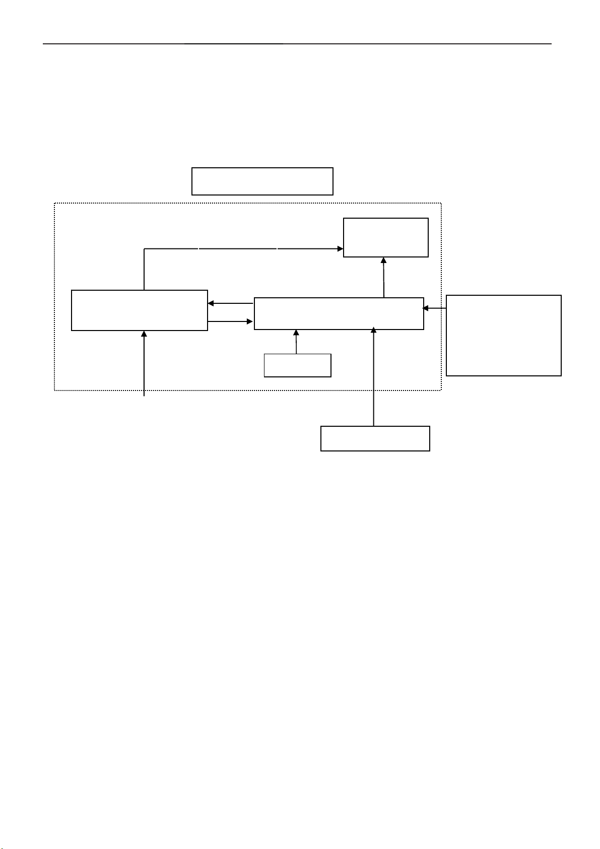
2. LCD Monitor Description
The LCD MONITOR will contain a main board, a power board, an audio board and a key board which house the flat
panel control logic, brightness control logic and DDC.
The power board will provide AC to DC Inverter voltage to drive the backlight of panel and the main board chips
each voltage.
PWPC board
(Include: adapter, inverter)
AC-IN
100V-240V
Monitor Block Diagram
CCFL Drive.
Main Board
Keyboard
Flat Panel and
CCFL backlight
HOST Computer
RS232 Connector
For white balance
adjustment in factory
mode
Video signal DDC
4
Page 5
19" LCD Color Monitor AOC 919Swa
3. Operating Instructions
3.1 General Instructions
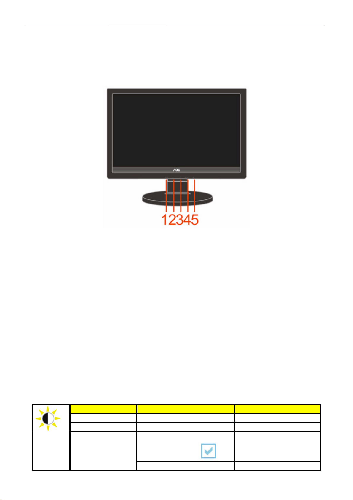
Press the power button to turn the monitor on or off. The other control knobs are located at front panel of the monitor
(See Figure ). By changing these settings, the picture can be adjusted to your personal preferences.
* The power cord should be connected.
* Press the power button to turn on the monitor. The power indicator will light up.
3.2 Control Buttons
1. Auto / Exit
2. Eco mode / -
3. Volume / +
4. Menu / Enter
5. Power Button & Indicator
3.3 Adjusting the Picture
• Press the MENU-button to activate the OSD window.
• Press+ or - to navigate through the functions. Once the desired function is highlighted, press the
MENU-buttonto activate it.If the function selected has a sub-menu, press + or - again to navigate through
the sub-menu functions.Once the desired function is highlighted, press MENU-button to activate it.
• Press+ or - to change the settings of the selected function. To exit and save, select the exit function. If you
want to adjust any other function, repeat steps 2-3.
• OSD Lock Function: To lock the OSD, press and hold the Menu button while the monitor is off and then
press power button to turn the monitor on. To un-lock the OSD - press and hold the Menu button while the
monitor is off and then press power button to turn the monitor on.
• Eco Mode hot key : Press the Eco key continuously to select the Eco mode of brightness when there is no
OSD ( Eco mode hot key may not be available in all models).
• Volume adjustment hot key : When there is no OSD , press Volume (+) to active volume adjustment bar,
press - or + to adjust volume ( Only for the models with speakers).
• Auto configure hot key: When the OSD is closed, press Auto/Source button continuously about 2 second to
do auto configure.
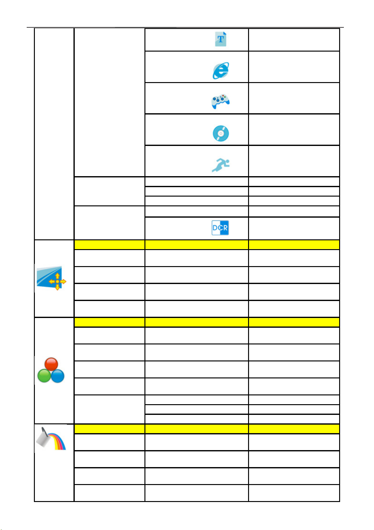
Luminance Adjust Range Description
Brightness 0-100 Backlight Adjustment
Contrast 0-100 Contrast from Digital-register.
Eco mode
Standard
Text Mode
5
Standard Mode
Page 6
19" LCD Color Monitor AOC 919Swa
Text
Internet
Game
Movie
Sports
Gamma
DCR
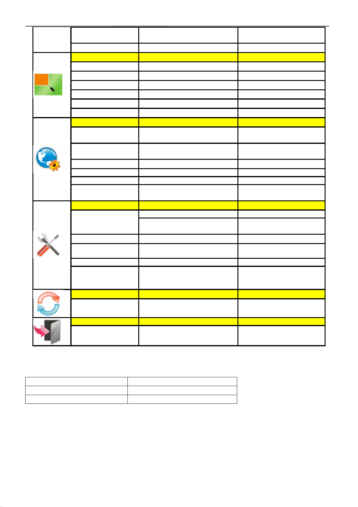
Image Setup
Clock 0-100
Phase 0-100
H.Position 0-100
V.Position 0-100
Color Temp.
Warm
Normal
Cool
sRGB
User
Color Boost
Full Enhance on or off
Nature Skin on or off
Green Field on or off
Sky-blue on or off
Gamma1 Adjust to Gamma1
Gamma2 Adjust to Gamma 2
Gamma3 Adjust to Gamma 3
Off
On
6500K
7300K
9300K
Red Red Gain from Digital-register
Green Green Gain Digital-register.
Blue Blue Gain from Digital-register
Internet Mode
Game Mode
Movie Mode
Sports Mode
Disable dynamic contrast ratio
Enable dynamic contrast ratio
Adjust picture Clock to reduce
Vertical-Line noise.
Adjust Picture Phase to reduce
Horizontal-Line noise
Adjust the verticalposition of the
picture.
Adjust the horizontal position of
the picture.
Recall Warm Color Temperature
from EEPROM.
Recall Normal Color
Temperature from EEPROM.
Recall Cool Color Temperature
from EEPROM.
Recall SRGB Color
Temperature from EEPROM.
Disable or Enable Full Enhance
Mode
Disable or Enable Nature Skin
Mode
Disable or Enable Green Field
Mode
Disable or Enable Sky-blue
Mode
6
Page 7
19" LCD Color Monitor AOC 919Swa
A
AutoDetect on or off
Demo on or off Disable or Enable Demo
Picture Boost
Frame Size 14-100 Adjust Frame Size
Brightness 0-100 Adjust Frame Brightness
Contrast 0-100 Adjust Frame Contrast
H. position
V.position
Bright Frame on or off Disable or Enable Bright Frame
OSD Setup
H.Position 0-100
V.Position 0-100
Timeout 5-120 Adjust the OSD Timeout
Transparence 0-100 Adjust the transparence of OSD
Off Timer Select the OSD language
Language 0~24hours
Extra
Input Select
Auto Config yes or no
Image Ratio wide or 4:3
DDC-CI yes or no Turn ON/OFF DDC-CI Support
Information
Reset
0-100 Adjust Frame horizontal Position
0-100 Adjust Frame vertical Position
Analog
Disable or Enable AutoDetect
Mode
Adjust the verticalposition of
OSD
Adjust the horizontal position of
OSD
Select timing to turn off the
monitor.
Select Analog Sigal Source as
Input
uto adjust the picture to default
Select wide or 4:3 format for
display
Show the information of the
main image and sub-image
source
Reset yes or no Reset the menu to default
Exit
Exit Exit the main OSD
LED Indicator
Status LED Color
Full Power Mode Green or Blue
Active-off Mode Orange or red
7
Page 8
19" LCD Color Monitor AOC 919Swa
4. Input/Output Specification
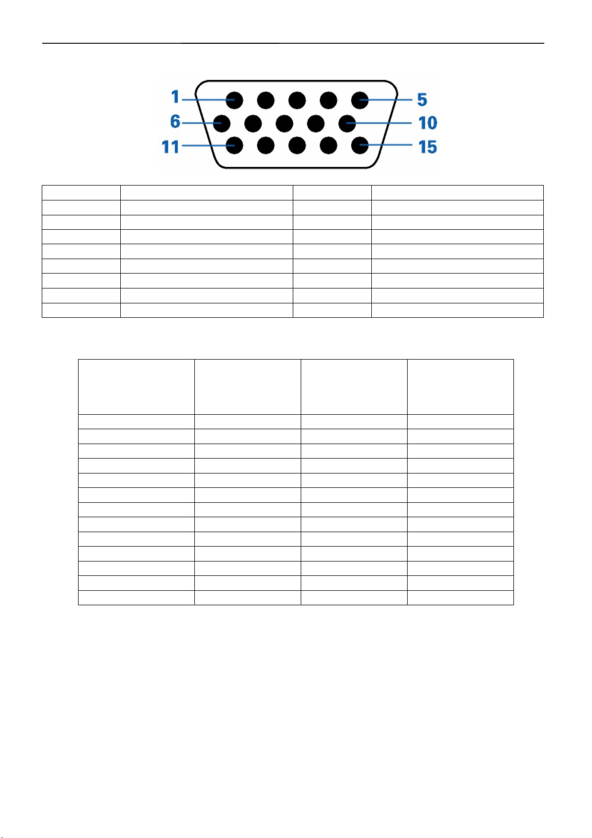
4.1 Input Signal Connector
Pin Number 15-Pin Side of the Signal Cable Pin Number 15-Pin Side of the Signal Cable
1 Video-Red 9 +5V
2 Video-Green 10 Ground
3 Video-Blue 11 N.C.
4 N.C. 12 DDC-Serial data
5 Detect Cable 13 H-sync
6 GND-R 14 V-sync
7 GND-G 15 DDC-Serial clock
8 GND-B
4.2 Factory Preset Display Modes
HORIZONTAL
STAND RESOLUTION
Dos-mode 720 x 400 31.47 70
VGA 640 x 480 31.47 60
VGA 640 x 480 37.5 75
SVGA 800 x 600 37.879 60
SVGA 800 x 600 46.875 75
XGA 1024 x 768 48.363 60
XGA 1024 x 768 56.476 70
XGA 1024 x 768 60.02 75
XGA 1024 x 768 48.78 60
XGA 1024 x 768 60.241 75
SXGA 1280 x 1024 64 60
SXGA 1280 x 1024 80 75
WXGA 1440×900 55.93 60
FREQUENCY(kHZ)
VERTICAL
FREQUENCY(Hz)
8
Page 9
19" LCD Color Monitor AOC 919Swa
5 Panel Specification
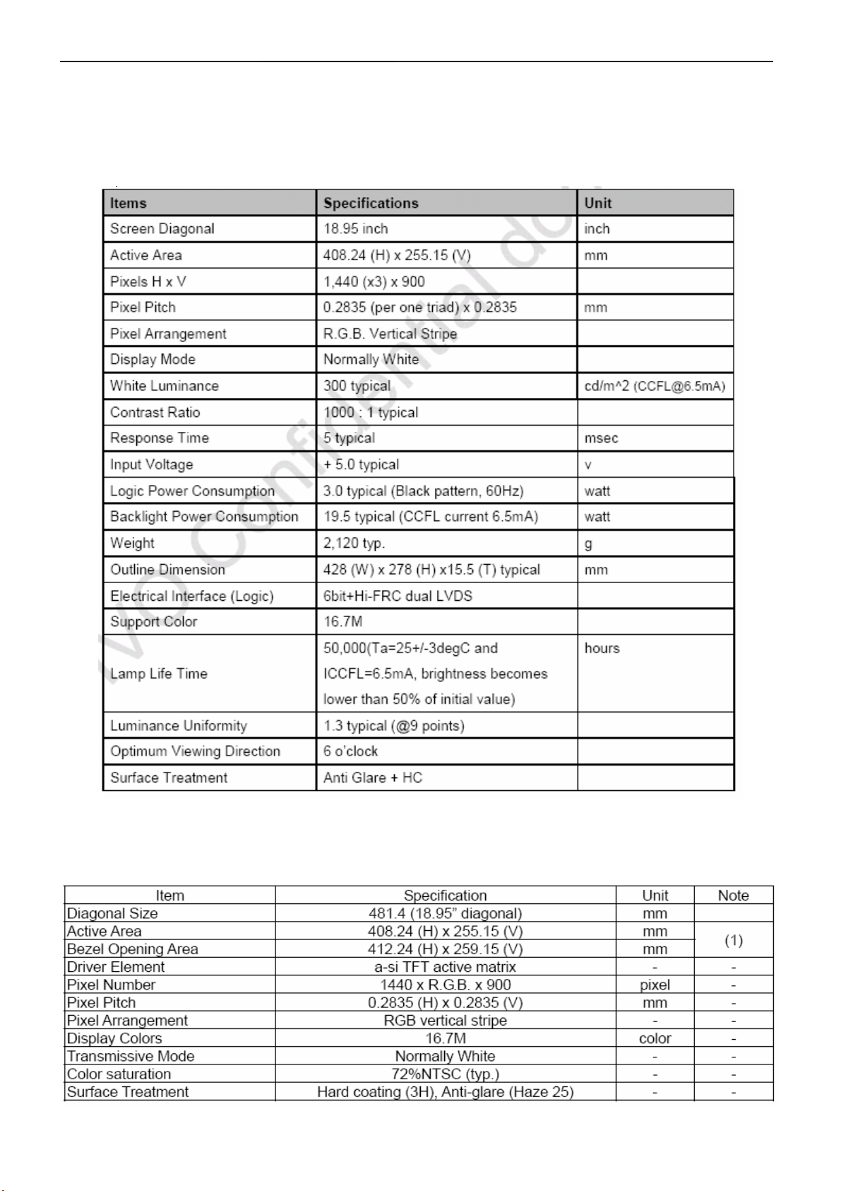
5.1 Display Characteristics
M190MWW3
The M190MWW3 is a color active matrix thin film transistor (TFT) liquid crystal display (LCD) that uses amorphous
silicon TFT as a switching device. It is composed of a TFT LCD panel, a timing controller, voltage reference,
common voltage, driver DC-DC converter, column driver, and row driver circuit. This TFT LCD has a 19-inch
diagonally measured active display area with WXGA+ resolution (1440 vertical by 900 horizontal pixel array).
TPM190A1
TPM190A1(M190A1-P0A) is a 19” wide TFT Liquid Crystal Display module with 4 CCFL Backlight unit and 30 pins
2ch-LVDS interface. This module supports 1440 x 900 WXGA+ mode and can display 16.7M colors. The front metal
frame for backlight is not built in, and need monitor front plastic bezel instead.
9
Page 10
19" LCD Color Monitor AOC 919Swa
Note (1) Please refer to the attached drawings for more information of front and back outline dimensions.
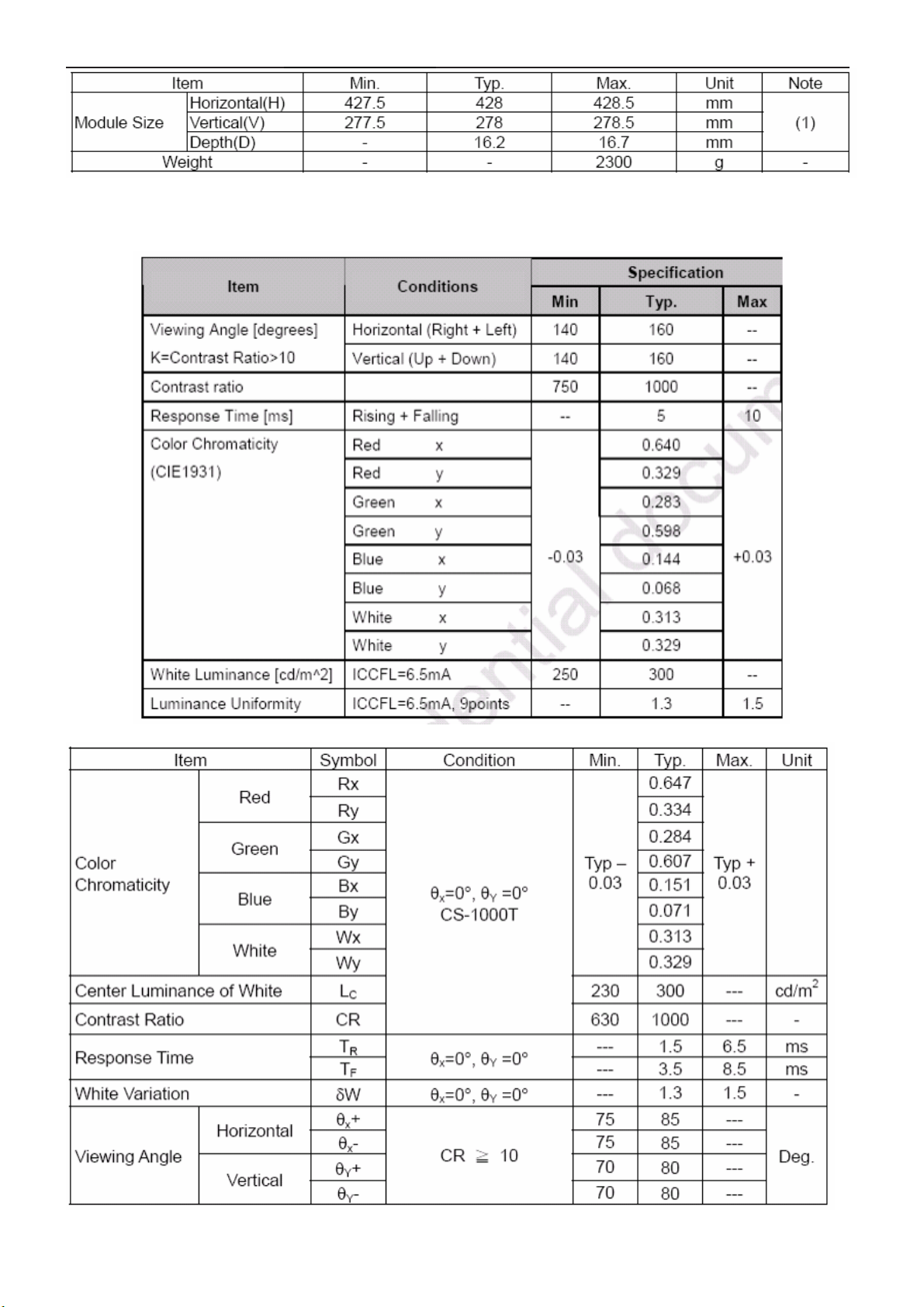
5.2 Optical Characteristics
M190MWW3
TPM190A1
10
Page 11
19" LCD Color Monitor AOC 919Swa
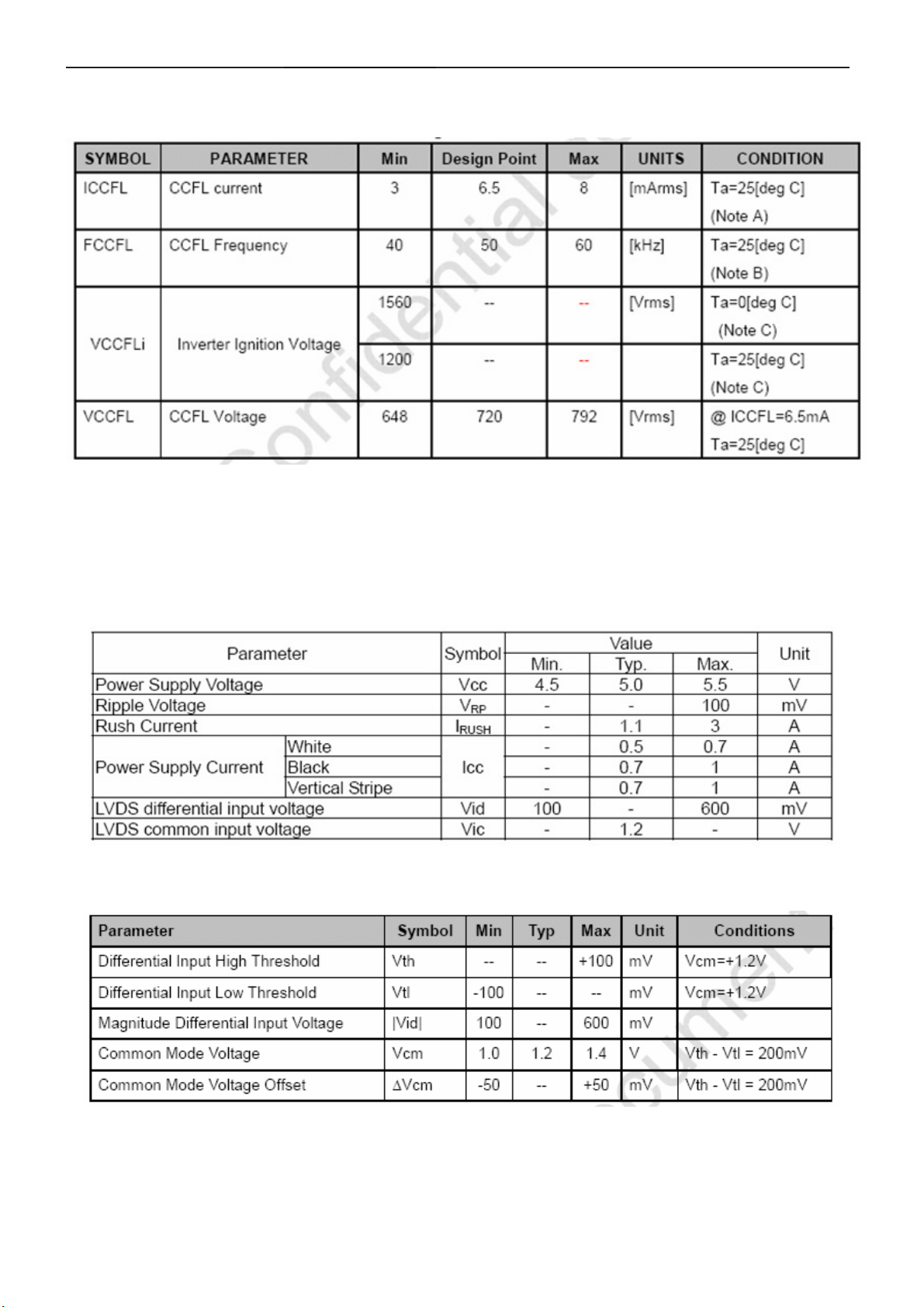
5.3 Electrical Characteristics
1.TFT LCD Module:
M190MWW3
Note:
A. If it exceeds MIN/MAX values, then "CCFL Life", "ON/OFF Cycle", and "SAFETY" will not be guaranteed.
B. CCFL Frequency should be carefully determined to avoid interference between inverter and TFT LCD.
C. The voltage over specified value (VCCFLi) should be applied to the lamp more than 1 second after startup.
Otherwise, the lamp may not be turned on. The used lamp current is the lamp typical current. The inverter should be
able to give out a power that has a generating capacity of over 1560 voltage. Lamp units need to over 1560 voltage
for ignition.
TPM190A1
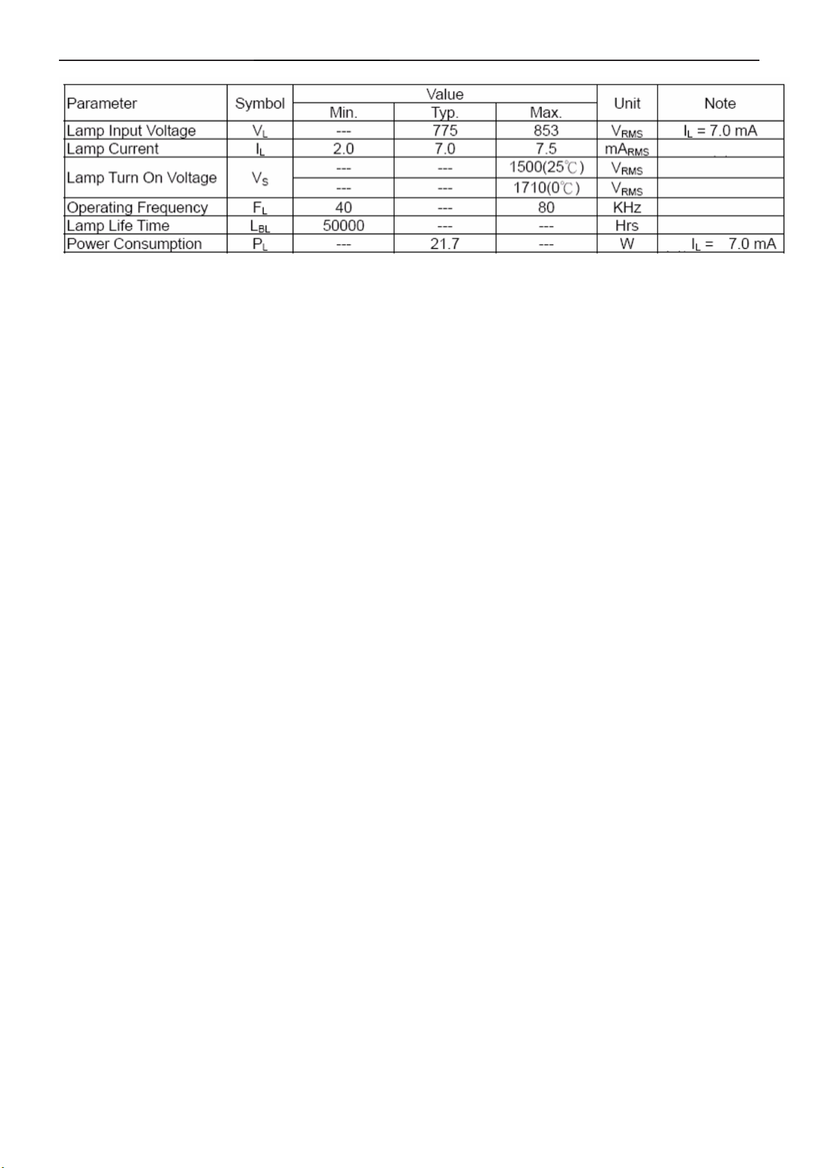
2.Back Light Unit:
M190MWW3
11
Page 12
19" LCD Color Monitor AOC 919Swa
TPM190A1
12
Page 13
19" LCD Color Monitor AOC 919Swa
6. Block Diagram
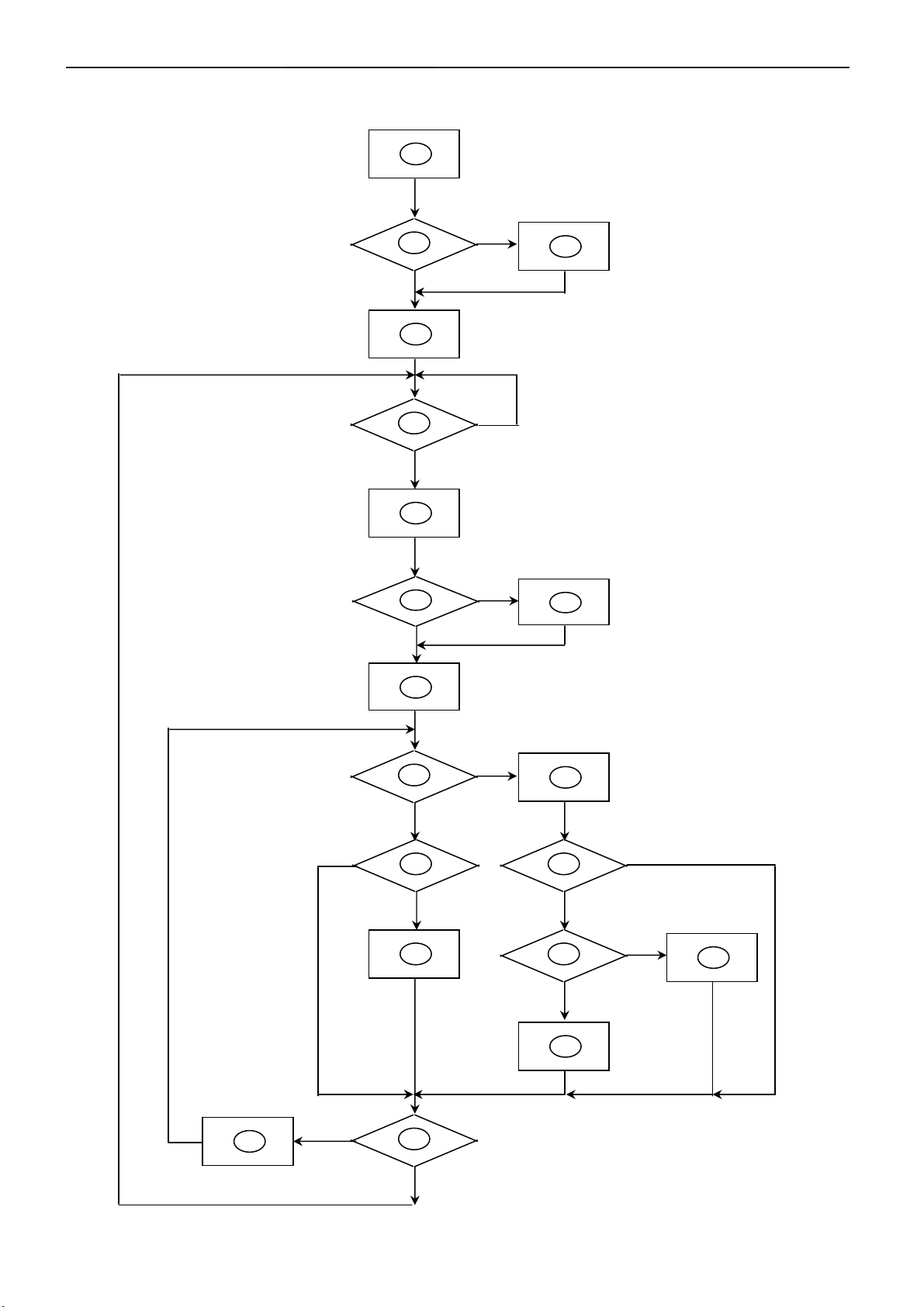
6.1 Software Flow Chat
1
2
N
4
5
Y
6
7
Y
N
N
3
18
9
10
Y
N
N
12
Y
14
19
N
11
13
15
17
N
Y
N
Y
16
Y
13
Page 14
19" LCD Color Monitor AOC 919Swa
REMARK:
1) MCU initialize.
2) Is the EPROM blank?
3) Program the EPROM by default values.
4) Get the PWM value of brightness from EPROM.
5) Is the power key pressed?
6) Clear all global flags.
7) Are the AUTO and SELECT keys pressed?
8) Enter factory mode.
9) Save the power key status into EPROM.Turn on the LED and set it to green color.Scalar initializes.
10) In standby mode?
11) Update the lifetime of back light.
12) Check the analog port, are there any signals coming?
13) Does the scalar send out an interrupt request?
14) Wake up the scalar.
15) Are there any signals coming from analog port?
16) Display "No connection Check Signal Cable" message. And go into standby mode after the message
disappear.
17) Program the scalar to be able to show the coming mode.
18) Process the OSD display.
19) Read the keyboard. Is the power key pressed?
14
Page 15
19" LCD Color Monitor AOC 919Swa
(
(
)
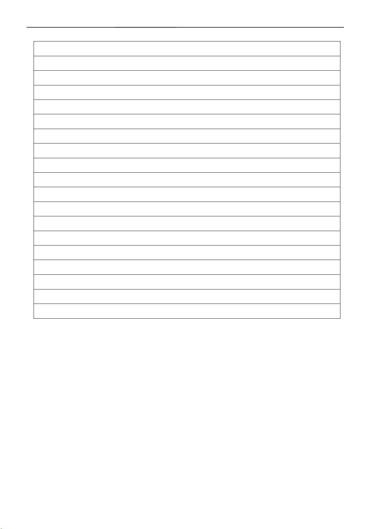
6.2 Electric Block Diagram
6.2.1 Main Board
FLASH MEMORY
SST25LF020A-33-4C-SAE
U402)
Crystal 24.576MHz
(X401)
Connector
Scalar HX6803-A000LAG
(Include :MCU,ADC,OSD etc)
D-Sub
(U401)
Panel Interface
(CN405)
Key Control
Interface
CN408
EEPROM
M24C04-WMN6TP
DDC1_SDA
DDC1_SCL
M24C02-WMN6TP
(CN101)
EEPROM
(U101)
(U406)
15
Page 16

19" LCD Color Monitor AOC 919Swa
A
6.2.2 Inverter / Power Board
C input
Audio
Lamp
EMI filter
Feedback
Circuit
+5V
Rectifier,Filter
(R904,R905,
PWM Control IC
Output
Circuit
Bridge
Start Circuit
R906)
LD7576
(IC901)
Transformer
(PT801)
Audio Power Amplifier
APA2069JITUL
Transformer
(T901)
Power Switch
Photocoupler
(IC601)
(Q901)
(IC903)
MOSFET
(Q805,Q806)
PWM Control IC
OZ9938GN
(IC801)
Rectifier diodes
Regulator
(IC904)
16V
ON/OFF
DIM
PID
CN601(Phone Jack)
CN602
16V
5V
16
Page 17

19" LCD Color Monitor AOC 919Swa
7. Schematic
7.1 Main Board
H_Sync
R101 80 OHM
V_Sy nc
R105
2K2 1/16W 5%
CN101
R110
DDC1_SCL3
DDC1_SDA3
DDC1_SCL
DDC1_SDA
100R 1/16W 5%
R113
100R 1/16W 5%
DSUB_SCL VGA_ PLUG
DSUB_SDA
15
14
13
12
11
10
5
9
4
8
3
7
2
6
1
DB15
17 16
R106
2K2 1/16W 5%
DSUB_5V
B_GND
VGA_B+
G_GND
VGA_G+
R_GND
VGA_R+ VGA_G+
ZD103
UDZSNP5.6B
C102
22pF
C103
22pF
1 2
R102 1K 1/16W 5%
R103 1K 1/16W 5%
DSUB_5V
DSUB_5V 5
ZD104
UDZSNP5.6B
1 2
DSUB_H 3
DSUB_V 3
VGA_B+
B_GND
G_GND
R122
CHIP BEAD
R123
CHIP BEAD
R107
75R 1/16W 5%
R112
75R 1/16W 5%
C121
10pF
C120
10pF
R104
390R 1/16W 5%
R109
390 OHM 1/16W
R111
390R 1/16W 5%
C101
0.047uF
C106
0.047uF
C107
0.047uF
DSUB_B+ 3
DSUB_SOG 3
DSUB_G+ 3
GND POWER DGND
DSUB_SDA
DSUB_SCL
VGA_G+
VGA_R+ VGA_B+
U103
1
I/O1
2
GND
I/O23I/O3
AZC099-04S
U102
1
I/O1
2
GND
I/O23I/O3
AZC099-04S
I/O4
VDD
I/O4
VDD
H_Sync
6
5
V_Sy nc
4
6
5
4
5V_ESD
候綼
ESD_5V
候綼
C115
NC
U10 3
C114
NC
U10 1
C118
0.1uF/ 16V
CMVCC15
CMVCC1
U101
1
A0
VCC
2
A1
WP
3
A2
SCL
VSS4SDA
M24C02-WMN6TP
5V_ESD
8
7
6
5
FB104
300 OHM
4K7 1/16W 5%
EDID_W P
DDC1_SCL
DDC1_SDA
VGA_R+
R_GND
2
R119
R124
CHIP BEAD
DSUB_5V
1
3
R120
10K 1/16W 5%
DSUB_5V 5
D105
BAV70
R121
10K 1/16W 5%
T P V ( Top Victory Electronics Co . , Ltd. )
絬 隔 瓜 絪 腹
Key Component
G2681-1-4-X-1-090921
02.Input
Date
R116
75R 1/16W 5%
R115
390R 1/16W 5%
C122
10pF
DET_CABLE3
VCC3.3
OEM MO DE L
TPV MODEL
PCB NAME
Sheet
C110
0.047uF
VCC3.3 3,5
R118
1K 1/16W 5%
R125
VGA_PLUG
4K7 1/16W 5%
TBD
AOC 931SN D
G2681-1-4
of
25Monday, September 21, 2009
DSUB_R+ 3
EDID _WP
Q410
2N3904S-RTK/PS
Size
Rev
称爹
B
称爹
>
<
17
Page 18

19" LCD Color Monitor AOC 919Swa
VCC3.32,5
VCC1.85
VCC3.3
C408
0.22uF16V
1K 1/16W 5%
FB405
1 2
BEAD
FB406
1 2
BEAD
C442
10uF/10V
VCC1.8
FB409
1 2
220OHM
CMVCC
RST
C456
1uF/16V
Q412
2N3904S-RTK/PS
R482
10K 1/16W 5%
8
7
SPI_WP#
3
SST25LF020A-33 -4C-SAE
VCC3.3
R453
R452NCR451
NC
CSNSDO SCK
R456
R455
R454
1K 1/16W 5%
NC
POWER_ON_LATCH
POWER_ON_LATCH Setting
SPI-Flash
Spansion(2M)
SST-010A
PMC,MXIC(1M)
PMC,MXIC(2M)
SST-020A
SDO
0
1
0
1
0
1
1K 1/16W 5%
CSN
VCC3IO
C438
0.1uF/16V
C441
10uF/10V
VDD
HOLD#
WP#
VSS4SDI
SCK
0
0
1
1
0
0
U402
SDO
CE#
SCK
0
0
0SST-010
0
1
0
VDDA_AD
VDDP_AD
VDDDP_AD
C406
0.1uF/16V
2
1
6
5
C404
0.1uF/16V
VSSA_AD
C433
0.1uF/16V
C403
0.1uF/16V
C439
0.1uF/16V
VCCK
SDI
CSN
SCK
SDO
C407
0.1uF/16V
C437
0.1uF/16V
VSSP_AD
VSSP_AD
VCCLVPVCCP
C436
0.1uF/16V
CN408
CONN
CN409
NC/CONN
6
5
4
3
2
1
7
6
5
4
3
2
1
TOUCH_POWER
綼
IC PIN
GND
IC PIN
VDDP_AD
綼
VCC3.3
GND
10K 1/16W 5%
C405 0.01uF/25V
R402
1K6 OHM 1/16W 5%
C409
0.1uF/16V
R450
5K1 OHM 1/16W 5%
C455
10uF/10V
R421
3.9K OHM 1/16W
C413
0.1uF/16V
C401
0.1uF/16V
VREF
C402
4.7uF/16V
R469 0R05 1/16W
GND
XTAL_OUT
GND
VCC3.3
R427
C414
0.1uF/16V
Near to Connect
DSUB_B+2
DSUB_G+2
DSUB_SOG2
DSUB_R+2
DSUB_H2
DSUB_V2
DDC1_SDA2
DDC1_SCL2
SDO
R468 N CVCC3.3
RST
R401
1M 1/16W 5%
X401
24.576MHz
C411
33pF
X1 GROUNG
SHIELDING
CSN
SCK
SDI
R428
3.9K OHM 1/16W
C415
0.1uF/16V
C412
33pF
KEY1
KEY2
POWER_KEY #
LED_GRN/BLUE
LED_ORA NGE
VCCP
6
B
7
G
8
SOG
9
R
11
HSYNC
12
VSYNC
17
DDCA_SDA/RS232_TX/GPIO17
18
DDCA_SCL/RS232_RX/GPIO18
4
VREF(1.2 5V)
14
FILT
22
SDO
23
CSN
24
SCK
25
SDI
62
TSTMD
63
RST_N
64
XTAL _ O U T
1
XTAL _ I N
R487
C416
10K 1/16W 5%
0.1uF/16V
VCCLVP
VCC3IO
VCCK
2
32
52
41
VCCP(1.8V)
VCCK(1.8V)
VCCK(1.8V)
VCCLVP(1. 8V)
HX6803-A000LAG
LVDS
VSSP_AD
VSSA_AD
GNDIO
GNDIO
5
15
31
53
VSSA_AD
VSSP_AD
GNDIO
GNDIO
GND
R463 NC
R464 NC
R485 NC/1K
R486 NC/1K 1/16W 5%
C417
0.1uF/16V
FB404
VCC3.3
NC
ZD401
NC/UDZSNP5.6B
VDDDP_AD
VDDA_AD
VDDP_AD
10
16
30
54
VCC3IO(3.3V)
VCC3IO(3.3V)
VDDP_AD(3.3V)13VDDA_AD(3.3V)
VDDDP_AD(3.3V)
PWMB/GPIO10
PWMC/GPIO11
PWMD/GPIO12
GPIO04/PWMC
GPIO03/PWMB
GPIO02/RS232_RX
GPIO01/RS232_TX
GPIO00/PWMD
USRD_MSCL/GPIO16
USRD_MSDA/GPIO15
R488
10K 1/16W 5%
TOUCH_POWER
C445
NC
1 2
LVA3P
LVA3N
LVA2P
LVA2N
LVA1P
LVA1N
LVA0P
LVA0N
LVB3P
LVB3N
LVBCKP
LVBCKN
LVB2P
LVB2N
LVB1P
LVB1N
LVB0P
LVB0N
GPIO06
GPIO05
SAR0
SAR1
SAR2
PA0
33
PA1
34
PA4
35
PA5
36
PA6
37
PA7
38
PA8
39
PA9
40
PB0
42
PB1
43
PB2
44
PB3
45
PB4
46
PB5
47
PB6
48
PB7
49
PB8
50
PB9
51
55
R411 100R 1/16W 5%
56
R412 100R 1/16W 5%
R420 100R 1/16W 5%
57
58
R419 NC/61G0402101
59
60
R418 NC /61G0402101
3
61
29
28
27
26
19
USRD_MSCL
21
USRD_MSDA
20
U401
CN406
1
2
3
4
5
6
7
8
NC/CONN
CN402
1
2
3
4
5
6
NC/CONN
CN407
1
2
3
4
5
6
7
NC/CONN
SPI_WP#
UDP_WP
PA[0..1]
PA[4..9]
PB[0..9]
AC_DET
adj_BACKLIGHT 5
Mute 5
Volume# 5
DET_CABLE 2
on_Panel 4
on_BACKLIGHT 5
絬 隔 瓜 絪 腹
Key Component
PA[0.. 1] 4
PA[4.. 9] 4
PB[0.. 9] 4
KEY2
KEY1
10K 1/16W 5%
R415 4K7 1/16W 5%
R416 4K7 1/16W 5%
R480 NC
R490 NC/61G0402101
VCC3.3
R460
10K 1/16W 5%
R471 100R 1/16W 5%
R472 100R 1/16W 5%
100R 1/16W 5%
R473
T P V ( Top Victory Electronics Co . , Ltd. )
G2681-1-4-X-1-090921
03.Scale r
Date
CMVCC5
R465
6K8 1/16W 5%
AC_DET
R466
POWER_KEY#
0R05 1/16W
R457
10K 1/16W 5%
SPI_WP#
VCC3.3 VCC3.3
R407
Q402
PMBS3906
R414
POWER_KEY#
120R 1/16W 5%
PANEL_ID# 7
USER DATA
R462
10K 1/16W 5%
R461
10K 1/16W 5%
OEM MOD EL
TBD
TPV MOD EL
AOC 931SN D
G2681-1-4
PCB NAME
Sheet
CMVCC
R467 10K 1/16W 5%
C450
0.1uF/16V
VCC3.3
10K 1/16W 5%
LED_GRN/BLUE
U406
8
VCC
7
WC
6
SCL
5
M24C04-WMN6TP
35Monday, Septem ber 21, 2009
of
VSS4SDA
R404
NC
E1
E2
C444
0.22UF 10V
1
2
3
Q401
PMBS3906
R410
120R 1/16W 5%
Size
Rev
称爹
LED_ORANGE
<
称爹
Custom
>
18
Page 19

19" LCD Color Monitor AOC 919Swa
3
D
PANEL_VCC
on_Panel3
1
G
AO3401L
4K7 1/16W 5%
2
S
R435
on_Panel
PA[0.. 1]3
PA[4. .9]3
C446
NC/ 65G0402104 15
PA[0. .1]
PA[4..9]
R433
10K 1/16W 5%
R436
51K OHM 1/16W
Q404
PMBS3906
PA0
PA1
PA4
PA5
PA6
PA7
PA8
PA9
C419
0.1uF/ 16V
C447
NC
PB[0.. 9]3
R481
47K 1/16W 5%
Q405
AO3401
PB[0..9]
FB402
120OHM
VCC3.3D 5
PA1
PB3
PA5 PA4
PA7
PA9
PB1
PB3
PB7
PB9
PANEL_VC C
C421
+
100UF25V
CMVCCD 5
Ripple Current NG
PANEL_VCC
R434
330 OHM 1/4W
PB0
PB1
PB2
PB3
PB4
PB5
PB6
PB7 PB2
PB8
PB9
CN403
CONN
2
4
6
8
10
12
14
16
18
20
22
24
26
28
30
1
3
5
7
9
11
13
15
17
19
21
23
25
27
29
LVDS OUTPUT
C420
0.1uF/ 16V
PA0
PA1
PB2
PB3
PA4
PA5
PA6
PA7
PA8
PA9
PB0
PB1
PB3
PB4
PB5
PB6
PB7
PB8
PB9
PA0
PB2
PA6
PA8
PB0
PB2
PB4PB5
PB6
PB8
CN405
1
2
3
4
5
6
7
8
9
10
11
12
13
14
15
16
17
18
19
20
21
22
23
24
25
26
27
28
29
30
T P V ( Top Victory Electronics Co . , Ltd. )
絬 隔 瓜 絪 腹
Key Component
Date
G2681-1-4-X-1-090921
04.Out put
19
OEM MO D EL
TPV MO D EL
PCB NAME
Sheet
NC/ 33G801930F C H JS
TBD
AOC 931SN D
G2681-1-4
45Monday, Septem ber 21, 2009
of
Size
Rev
称爹
<
A4
称爹
>
Page 20

19" LCD Color Monitor AOC 919Swa
ESD_5V
CN404
CONN
FB407 300 O HM
CMVCC
CMVCC 3
9
8
7
6
5
4
3
2
1
CMVCC
CMVCC
BKLT_VBRI
BKLT_EN
Volume
Mut e
D402
SR24
R491 NC
CMVCCD 4
CMVCC1
R449
NC
Mut e 3
PANEL_ID#
D403
BAT54C
ESD_5V 2
CMVCC1 2
VCC3.3 VCC3.3
R437
C425
NC
10K 1/16W 5%
R478 NC
Q406
2N3904S-RTK/PS
BKLT_EN
R440
4K7 1/16W 5%
R439
10K 1/16W 5%
on_BACKLIGH T 3
DSUB_5V
DSUB_5V2
CMVCC1
1
2
D401
NC/ BAV70//93G 64 42 P
3
R438
3.3 OHM 2W
C431
0.1uF/ 16V
VI3VO
C424
+
100uF M 16V
U405
2
4
VO
GND
1
C432
0.1uF/ 16V
VCC1.8
+
C423
100uF M 16V
VCC1.8 3
BKLT_VBRI
R476
0R05 1/16W
VCC3.3
R441
1K 1/16W 5%
Q411
2N3904S-RTK/PS
R477
4K7 1/16W 5%
R475
10K 1/16W 5%
adj_BACKLIGH T 3
VCC3.3 VCC3.3
R446
Volume
NC/ 10K 1/16W 5%
Q408
2N3904S-RTK/PS
R448
4.7K 1/16W
R447
NC
Volume# 3
VCC3.3D
VCC3.3D 4
Size
Rev
称爹
B
称爹
>
<
CMVCC1
T P V ( Top Victory Electronics Co . , Ltd. )
絬 隔 瓜 絪 腹
Key Component
Date
MVC C
+
C426
100uF M 16V
G2681-1-4-X-1-090921
05.POWER
C428
0.1uF/ 16V
3
VIN
AP1117E33LA
1
2
3
U404
VOUT
VSS
4
1
4
U403
ADJ(GND)
VOUT
VIN
NC/ AP1117D33LA
2
OEM MODEL
TPV MO DE L
PCB NAME
Sheet
FB408 NC ,71G 56Z601
VCC3.3
VCC3.3 2,3
+
C422
0.1uF/ 16V
C427
100uF M 16V
TBD
931SN D
G2681-1-4
of
55Monday, September 21, 2009
20
Page 21

19" LCD Color Monitor AOC 919Swa
7.2 Power Board
PID
+16V
ON/OF F
DIM
R813
470K 1/10W 5%
C803
NC
R815
NC
R814
NC
R816
10K 1/10W 1%
C805
10N
C804
2.2uF/16V
R801
2.4K OHM 1/ 10W
ZD801
RLZ5.6B
1 2
C806
1uF/16V
R817
1M 1/10W 5%
Q801
PMBS3904
R802
22R 1/8W
R818
100K 1/10W 5%
R819
100K 1/10W 5%
R850
NC
ZD802
RLZ5.6B
5K1 1/8W
1 2
C813
33NF 25V
R803
1
2
3
4
5
6
7
C801
0.047uF
IC801
DRV1
PGND
VDDA
DRV2
TIME R
GNDA
DIM
CT
ISEN
SSTCMP
VSEN
LCT
OVPT
ENA
NC18NC2
OZ9938GN
R823
390R 1/10 W 1%
SST
16
15
14
13
12
11
10
9
Q802
RK7002
1 2
R825
550OHM 1/10W
R824
5K1 1/10W
ZD803
RLZ5.6B
C802
0.047uF
D804 LL4148
R820
20K 1/10W 5%
C807
1uF
CT
C814
390P 50V
Q803
RK7002
R805
100R 1/10W 5%
D801 LL4148
R806 100R 1/8W
R804 5K1 1/8W
R807 100R 1/10W 5%
D803 LL4148
R808 100R 1/ 8W
R822
R821
20K OHM 1% 1/8W
1M 1/10W 5%
C808
180K 1/10W
C809
560pF50V
D805
LL4148
C815
0.047uF
R826
1M 1/10W 5%
D802 LL4148
C812
1000uF 25V
CT
SST
C810
0.047uF
C811
+
0.1uF
D806
3
D807
3
D808
3
Q805
4
G
3
S
2
G
1
S
AM4502C-T1-PF
Q806
4
G
3
S
2
G
1
S
AM4502C-T1-PF
BAV70
1
2
BAV70
1
2
BAV70
1
2
R842
10K 1/10W 5%
5
D
6
D
7
D
8
D
5
D
6
D
7
D
8
D
6.2M OHM 1/2W
R829
6K8 1/8W
R843
10K 1/10W 5%
6
2
5
R828
R830
NC
R844
10K 1/10W 5%
PT801
POWER X'FMR
8
91
62K 1/10W 5%
R838 1M 1/10W 5%
R839 1M 1/10W 5%
R840 1M 1/10W 5%
R841 1M 1/10W 5%
R845
10K 1/10W 5%
C816
22pF/6KV
C824
22pF/6KV
C817
2PF/6KV
C818
220pF
R836
R837
8K2 1/10W
LV2
LV1
LV3
LV4
C819
68pF/3KV
LV1
C820
68pF/3KV
LV2
L801
124
3
L802
124
NC
R827
RST CHIP MAX 0R05 1/10W
L
3
L
C821
68pF3KV
LV3
C822
68pF3KV
R846
R848
NC
C823
NC
Q804
NC
CN801
1
2
CN802
1
2
CN803
1
2
CN804
1
2
LV4
R847
NC
3
D809
1
2
BAV99
RST CHI P MAX 0R05 1/10W
R849
T P V ( Top Victory Electronics Co . , Ltd. )
絬 隔 瓜 絪 腹
Key Component
G2824-2-X-X-4-090627
02.Inverter
Date
21
OEM MODEL
TPV MODEL
PCB NAME
Sheet
919Swa
PWPC9941LH D1 2
715G2824-2
of
24Monday, June 29, 2009
Size
Rev
称爹
ODM MODEL
Custom
Page 22

19" LCD Color Monitor AOC 919Swa
IC903
8
7
9
10
12
11
VOL
MUTE
12
PID
R918100 OHM 1/4W
R919100 OHM 1/4W
R920100 OHM 1/4W
C924
0.1uF
IC904
AZ431AZ -AE1
3
R935 100 OH M 1/4W
R961 100 O HM 1/4W
R962 100 OHM 1/4W
D907
31DQ06FC 3
12
FB901
BEAD
R925
1K 1/8W
2
3
R926
1K 1/10W 1%
D908
FCQ10U 06
BOM
要变更
CN902
1
2
3
4
5
6
7
8
9
10
11
12
13
CONN
C912
0.001uF
C917
680uF25V
2
1
D906
FCH 10U15
C929
0.001uF
1000uF/25V
R949 100 OHM 1/4W
R950 100 OHM 1/4W
R951 100 OHM 1/4W
1
C939
+
C935
0.001uF
+
+
C916
1000uF/25V
!
2
!
!
R902
1M 1/4W
!
C902
1000PF/250VAC
CN901
SOCKET
1
+
-
4
4
3
3
BD901
GBU408
3
C904
NC
1
L901
30.0mH
2
C903
0.47uF/ 275V
R901
1M 1/4W
!
C901
1000PF/250VAC
12
FB904
1 2
BEAD
4
POWER X'FMR
5
6
1
3
!
C921
NC
C900
2200pF 250V
!
T901
PC123X2YFZ OF
43
FB902
1 2
+
C905
120uF/450V
c938
NC
1500P/2KV
!
IC901
RT4NC
!
C941
0.047uF/ 25V
NR901
NTCR
!
F901
FUSE
3
2
1
VCC
COMP
VCC
GND
LD7552DPS
CS
OUT
80OHM
R904
300K OHM 1/4W
R905
300K OHM 1/4W
R906
300K OHM 1/4W
5
6
7
8
C928
1000pF
C907
0.1uF
D903
R910
10R 1/4W
R912
220 OHM 1/4W
C909
470pF/25V
C906
1500pF2KV
D901
FR103
+
C908
22uF/50V
LL4148
R903
100K OHM 2W
PR1007R
Q901
STP9NK65ZF P
R938
10K 1/8W
R914
0R43 5% 2W
D900
!
C920
1000pF 250V
FB903
1 2
BEAD
R909
5.1 OHM 1/4W
!
GND 1 (009G6005 1)
GND 2 (009G6005 1)
HS3 with Heat-sink(90G6263 1)
HS4 with Heat-sink(90G6264 1)
DIM
ON/OFF
+5V1
+5V
C931
0.1uF
+
C918
680uF25V
+
L904
L
L903
L
R924
330R 1/8W 5%
470uF/16V
L905
L
C934
1000uF/25V
C915
+16V
C932
0.001uF
ZD902
RLZ18B
R943
470R 1/8W
R939
1K 1/8W
L906
2.2uH
C930
0.1uF
F903
R940
NC
R927
2.43K O HM 1% 1/10W
R930
2.43K O HM 1% 1/10W
F902
T4A 250V
+5V1
C940
0.1uF
T4A 250V
+5V
R946
150OHM2W
Q903
PMBS3904
+
ZD922
ZD921
RLZ5.6B
RLZ22B
1 2
1 2
R942
1K 1/10W 1%
FOR D908 Heat-sink(90G6264 1)
T P V ( Top Victory Electronics Co . , Ltd. )
Date
G2824-2-X-X-4-090627
03.Adapter
絬 隔 瓜 絪 腹
Key Component
OEM MO DEL
TPV MOD EL
PCB NAME
919Swa
PWPC9941LH D1 2
715G2824-2
Sheet
of
34Monday, June 29, 2009
Size
Rev
称爹
Custom
OD M MODEL
22
Page 23

19" LCD Color Monitor AOC 919Swa
+5V1
C603 0.47uF/ 16V
+
LOUT-
VDD
LOUT+
GND
GND
VDD
ROUT-
C602 0.47uF/ 16V
1
2
3
4
CONN
CN602
9
10
11
12
13
14
15
16
LOUT-
LOUT+
ROUT+
ROUT-
CN601
PHON EJAC K
4
5
3
2
1
R608
0R05 1/ 8W
+5V1
VOL
R604 10K 1/10W 5%
R605 10K 1/10W 5%
R606
C610 100pF
R602
10K 1/10W 5%
R603
10K 1/10W 5%
C611 100pF
6.2KOHM +-5% 1/10W
C604
100uF/25V
C609
1uF/ 25V
C601 0.47uF/ 16V
C606 0.47uF/ 16V
+5V1
10K 1/10W 5%
R607
6.2KOHM +-5% 1/10W
R610
10K 1/10W 5%
R601
C613
0.1uF /16V
10K 1/10W 5%
R609
C612
0.1uF/ 16V
IC601
8
SE/BTL
7
VOLUME
6
LIN -
5
GND
4
GND
3
RIN-
2
BYPASS
1
SHUTDOWN
APA2069JITUL
C608
1uF/ 25V
ROUT+
FB602
1 2
BEAD
Q601
MU TE
T P V ( Top Victory Electronics Co . , Ltd. )
絬 隔 瓜 絪 腹
Key Component
Date
G2824-2-X-X-4-090627
04.AUD IO
PMBS3904
23
IC with Heat-sink(90G6295-3)
OE M MOD E L
TPV MODEL
PCB NAME
Sheet
919swa
PWPC9941LHD1 2
715G2824-2
of
44Monday , J une 29, 2009
Size
Rev
称爹
A
ODM MODEL
Page 24

19" LCD Color Monitor AOC 919Swa
8. PCB Layout
8.1 Main Board
24
Page 25

19" LCD Color Monitor AOC 919Swa
25
Page 26

19" LCD Color Monitor AOC 919Swa
8.2 Power Board
26
Page 27

19" LCD Color Monitor AOC 919Swa
27
Page 28

19" LCD Color Monitor AOC 919Swa
8.3 Key Board
28
Page 29

19" LCD Color Monitor AOC 919Swa
9. Maintainability
9.1 Equipments and Tools Requirement
1. Voltmeter.
2. Oscilloscope.
3. Pattern Generator.
4. DDC Tool with an IBM Compatible Computer.
5. Alignment Tool.
6. LCD Color Analyzer.
7. Service Manual.
8. User Manual.
29
Page 30

19" LCD Color Monitor AOC 919Swa
9.2 Trouble Shooting
9.2.1 Main Board
1. NO SCREEN APPEAR
No power
Press power key and look if
the picture is normal
Please reinsert and make
sure the AC of 100-240 is
normal
Measure U404 Vout=3.3V
U405 Vout=1.8V
X401 oscillate waveforms
are normal
No power
NG
OK
OK
NG
NG
NG
Reinsert or check the
power section
Replace
U404,U405,CN404
Replace X401
OK
Replace U401
30
Page 31

19" LCD Color Monitor AOC 919Swa
No picture (LED orange)
Measure U404 Vout=3.3V
U405 Vout=1.8V
X401 oscillate waveforms are
normal
Check if the sync signal from
computer is output and video
cable is connected normally
No picture
OK
OK
OK
Replace U401
NG
NG
NG
Replace
U404,U405,CN404
Replace X401
Input the sync signal of
computer, or change the
cable
31
Page 32

19" LCD Color Monitor AOC 919Swa
White Screen
Check Correspondent
component.
Check FB402,Q405 is
broken,or CN405 solder?
White screen
Measure Q404base
is low level?
OK
NG
OK
Replace PANEL
NG
X401 oscillate
waveform is normal
OK
Check reset circuit of U401
is normal
OK
Replace U401
NG
NG
Replace X401
Check Correspondent
component.
32
Page 33

19" LCD Color Monitor AOC 919Swa
9.2.2 Power Board
1. No Power
Check ZD902 = 16V
NG
Check AC line volt 110V or 240V
OK
NG
Check AC input
Check the voltage of C905(+)
Check start voltage for the pin3 of IC901
OK
NG
Check bridge rectified circuit and F901 circuit
OK
NG
Check R904,R905,R906 and Change IC901
Check the auxiliary voltage
OK
NG
1) Check IC901,T901
2) Check OVP circuit
Check IC901 pin8 PWM wave
NG
OK
Check IC901
Check IC903,IC904,Q901,D906,D907
33
Page 34

19" LCD Color Monitor AOC 919Swa
2. W/LED No Backlight
Check C812 (+) =16V
OK
NG
Change adapter and MB
Check ON/OFF signal
OK
NG
Check main board
Check IC801 pin15=16V
OK
NG
Change Q801
Check the pin13 of IC801 have saw tooth wave
NG
Change IC801
OK
Check PT801 have the output of square of wave at short
OK
NG
Check the output of PT801
OK
NG
Check connecter & lamp
Change C819,C820,C821,C822
Change PT801
34
Page 35

19" LCD Color Monitor AOC 919Swa
9.2.3 Key Board
OSD is unstable or not working
Is Keypad board connecting normally?
NG
Connect Keypad Board
Is Button Switch normally?
OK
NG
Replace Button Switch
Is Keypad board normally?
OK
NG
Replace Keypad Board
OK
Check main board
35
Page 36

19" LCD Color Monitor AOC 919Swa
10. White- Balance, Luminance Adjustment
Approximately 30 minutes should be allowed for warm up before proceeding white balance adjustment.
Before started adjust white balance , please set the Chroma-7120 MEM Channel 3 to Warm (6500K) color, MEM
Channel 4 to Normal (7300K) color, MEM Channel 9 to Cool (9300K) color , and MEM Channel 10 to sRGB color
2
( our Warm color parameter is x = 283 ±30, y = 297 ±30, Y=180cd/m
2
317 ±30, Y=190cd/m
; Cool color parameter is x = 313 ±30, y = 329 ±30, Y = 200 cd/m2; sRGB color parameter
is x = 313 ±30, y = 329 ±30, Y = 180cd/m2)
How to setting MEM channel you can reference to chroma 7120 user guide or simple use “ SC” key and
“ NEXT” Key to modify xyY value and use “ID” key to modify the TEXT description Following is the procedure
to do white-balance adjust .
2. Setting the color temp. you want
A. MEM.CHANNEL 3 (Warm color):
Warm color temp. parameter is x = 283 ±30, y = 297 ±30, Y=180cd/m
B. MEM.CHANNEL 4 (Normal color):
Normal color temp. parameter is x = 301 ±30, y = 317 ±30, Y=190cd/m
C. MEM.CHANNEL 9 (Cool color):
Cool color temp. parameter is x = 313 ±30, y = 329 ±30, Y = 200 cd/m2
D. MEM.CHANNEL 10 (sRGB color):
; Normal color parameter is x = 301 ±30, y =
2
2
sRGB color temp. parameter is x = 313 ±30, y = 329 ±30, Y = 180cd/m2
3. Into Factory mode of AOC 919Swa
Press the MENU button, pull out the power cord, and then plug the power cord. Then the factory OSD will be at the
left top of the panel.
4. Bias adjustment:
Set the Contrast
to 50; Adjust the Brightness to 90.
5. Gain adjustment:
Move cursor to “-F-” and press MENU key
A. Adjust Warm (6500K) color-temperature
1. Switch the chroma-7120 to RGB-Mode (with press “MODE” button)
2. Switch the MEM.channel to Channel 3 (with up or down arrow on chroma 7120)
2
3. The LCD-indicator on chroma 7120 will show x = 283 ±30, y = 297 ±30, Y=180cd/m
4. Adjust the RED of color3 on factory window until chroma 7120 indicator reached the value R=100
5. Adjust the GREEN of color3 on factory window until chroma 7120 indicator reachedthe value G=100
6. Adjust the BLUE of color3 on factory window until chroma 7120 indicator reached the value B=100
7. Repeat above procedure (item 4,5,6) until chroma 7120 RGB value meet the tolerance =100±2
B. Adjust Normal (7300K) color-temperature
1. Switch the chroma-7120 to RGB-Mode (with press “MODE” button)
2. Switch the MEM.channel to Channel 4(with up or down arrow on chroma 7120)
3. The LCD-indicator on chroma 7120 will show x = 301 ±30, y = 317 ±30, Y=190cd/m
2
4. Adjust the RED of color3 on factory window until chroma 7120 indicator reached the value R=100
5. Adjust the GREEN of color3 on factory window until chroma 7120 indicator reachedthe value G=100
6. Adjust the BLUE of color3 on factory window until chroma 7120 indicator reached the value B=100
7. Repeat above procedure (item 4,5,6) until chroma 7120 RGB value meet the tolerance =100±2
36
Page 37

19" LCD Color Monitor AOC 919Swa
C. Adjust Cool (9300K) color-temperature
1. Switch the Chroma-7120 to RGB-Mode (with press “MODE” button)
2. Switch the MEM. Channel to Channel 9 (with up or down arrow on chroma 7120)
3. The LCD-indicator on chroma 7120 will show x = 313 ±30, y = 329 ±30, Y = 200 cd/m2
4. Adjust the RED of color1 on factory window until chroma 7120 indicator reached the value R=100
5. Adjust the GREEN of color1 on factory window until chroma 7120 indicator reached the value G=100
6. Adjust the BLUE of color1 on factory window until chroma 7120 indicator reached the value B=100
7. Repeat above procedure (item 4,5,6) until chroma 7120 RGB value meet the tolerance =100±2
D. Adjust sRGB color-temperature
1. Switch the chroma-7120 to RGB-Mode (with press “MODE” button)
2. Swit ch the MEM.channel to Channel 10 (with up or down arrow on chroma 7120)
3. The LCD-indicator on chroma 7120 will show x = 313 ±30, y = 329 ±30, Y = 180cd/m2
4. Adjust the RED of color3 on factory window until chroma 7120 indicator reached the value R=100
5. Adjust the GREEN of color3 on factory window until chroma 7120 indicator reachedthe value G=100
6. Adjust the BLUE of color3 on factory window until chroma 7120 indicator reached the value B=100
7. Repeat above procedure (item 4,5,6) until chroma 7120 RGB value meet the tolerance =100±2
E. Turn the Power-button off to quit from factory mode.
37
Page 38

19" LCD Color Monitor AOC 919Swa
11. Monitor Exploded View
38
Page 39

19" LCD Color Monitor AOC 919Swa
Item Description Item Description
1 BEZEL(L19WA-8Q1A) 11 HINGE
2 LENS 12 STAND TOP
3 KEY PAD 13 STAND
4 KEY BOARD 14 BASE8S2
5 PANEL 15 FOOT
6 POWERBOARD S1 SCREW
7 MAIN BOARD S2 SCREW
8 MAIN FRAME S3 SCREW
9 SPK S4 SCREW
10 REAR COVER19"
39
Page 40

19" LCD Color Monitor AOC 919Swa
12. BOM List
Note: The parts information listed below are for reference only, and are subject to change without notice. Please go
to http://cs.tpv.com.cn/hello1.asp for the latest information.
T99LHDDBWKA1ANE
Location Part NO. Description Remark
040G 58162435A P/N LABEL FOR MANUAL PE BAG
041G780061553A TCO'03 CARD
050G 600 1 W WHITE STRAP (1G004991)
050G 600 3 HANDLE2
050G 600 4 HANDLE 1
052G 1150 C INSULATING TAPE
052G 1186 SMALL TAPE
052G 1207 A Conductive Tape 45mm *25mm *0.08mm
052G 1211 B Conductive Tape 85mm *40mm *0.09mm
052G 1211527 Conductive Tape 75mm *45mm *0.08mm
052G6019 1 INSULATING TAPE
E07801 078G 322514 K SPK 8 OHM 1.5W 43X18 280 320mm KUAIDA
089G 173 56 4B AUDIO CABLE
E08902 089G 715HAAE01 SIGNAL CABLE
089G179J30N517 FFC CABLE
E08901 089G404A15N IS POWER CORD
E09503 095G8014 6TE01 HARNESS 6P-6P 160MM
0D1G1730 8120 SCREW
0M1G 130 5120 SCREW
705GH834068 19" STAND ASS'Y
E750 750GLJ190W3011N000 PANEL M190MWW3 R01 KS IVO
AM1G1740 12 47 CR3 SCREW
H15G0245O02 MAIN FRAME
H26G 800504 2A barcode
H40G 19N61579A ID LABEL
H40G 582615 9B CARTON LABEL
H40G 58261510A TCO BASIC SILVE LABEL
H41G780061597A QSG
H44G9033101 EPS
H44G9033201 EPS
H44G9033615 5B CARTON
H45G 77 6 PE PACKING
H45G 87 18 4H A EPE COVER
H70G200961521C CD MANUAL
KEPC7QAK KEY BOARD
PWPC9941LHD1 POWER BOARD
Q33G0170ABJ 1L0100 key pad
Q33G0171 1 1C0100 LENS
Q34G0265ABJC8B0100 REAR COVER19"
Q34G0316BBLC1B0130 BEZEL(L19WA-8Q1A)
Q45G 76 28 H A PE BAG FOR MANUAL
Q50G 4 10 TIE (Y1900221)
Q52G 1185 99 big carton tape for aoc
AM1G1740 10120 SCREW(M4*10)
H34G0026AED 1B0100 STAND
Q34G0299AED 1B0130 BASE8S2
Q37G0067015 HINGE
756GH9CB A1048 MAIN BOARD-CBPC9HDA1H1
U402 056G1133 81 SST25LF020A-33-4C-SAE
SMTCR-U402 100GAHL9001W11 MCU ASS'Y-056G1133 81
CN408 033G3802 6B Y W WAFER
40
Page 41

19" LCD Color Monitor AOC 919Swa
CN404 033G3802 9B Y W WAFER
CN405 033G801930F CH JS CONNECTOR
040G 45762412B CBPC LABEL
R438 061G152M33964L RST MOFR 3.3 OHM +-5% 2WS
CN101 088G 35315F XH D-SUB 15PIN VERTICAL CONN WITH SCREW
X401 093G 2258B J NXS24.576AC20F-KAB11
CN001 033G3802 6H WAFER 6P RIGHT ANGLE PITCH 2.0
D001 081G 12 1F GH
GND1 009G6005 1 GROUND TERMINAL
CN602 033G3802 4 WAFER PH-4
CN804 033G8021 2E F WAFER
CN803 033G8021 2E F WAFER
CN802 033G8021 2E F WAFER
CN801 033G8021 2E F WAFER
040G 45762412B CBPC LABEL
IC903 056G 139 3A IC PC123Y22FZ0F
NR901 061G 5810T RST NTCR 8 OHM +-20% 4A 13mm THINKING
C903 063G107K474 6S CAP X2 0.47UF K 275VAC
C822 065G 3J6806ET CAP CER 68PF J 3KV SL
C821 065G 3J6806ET CAP CER 68PF J 3KV SL
C820 065G 3J6806ET CAP CER 68PF J 3KV SL
C819 065G 3J6806ET CAP CER 68PF J 3KV SL
C817 065G 6J2096ET 2PF 5% SL 6KV
C824 065G 6J2206ET 22PF +-5% 6KV SL
C816 065G 6J2206ET 22PF +-5% 6KV SL
C902 065G305M1022BP Y2 1000PF M 250VAC Y5P
C901 065G305M1022BP Y2 1000PF M 250VAC Y5P
C920 065G306M1022BP 1000PF Y1.CAP
C900 065G306M2222BP 2200PF +-20% 250VAC
C905 067G 40Z12115K EC 120uF V 450V 20*40mm
C812 067G215H102 4K LOW ESR EC 1000UF 25V EB1E102M
C916 067G215P1023PV
C934 067G215P1023PV
C939 067G215P1024PV
C915 067G215P4713PV CAP 105C 470UF M 16V
C918 067G215S6814KV
C917 067G215S6814KV
L905 073G 253 91 V CHOKE COIL 3.5uH+-10%
L904 073G 253 91 V CHOKE COIL 3.5uH+-10%
L903 073G 253 91 V CHOKE COIL 3.5uH+-10%
PT801 080GL19T 32 DN X'FMR 785mH TK.2027R.101
T901 080GL22T 3 N X'FMR 490uH YUVA-822
CN901 087G 501 32 DL AC SOCKET DIP 3PIN+2PIN GROUND
CN601 088G 30214K DC
D907 093G 60519 DIODE SR560 5A/60V DO-27 SECOS
CN902 095G 82014TE01 HARNESS 14P-9P 140MM
705GQ757014 Q901 ASS'Y
705GQ793054 D906 ASS'Y
705GQ793055 D908 ASS'Y
PW9941LHD1SMT POWER BOARD FOR SMT
HS1 Q90G6295 3 HEAT SINK
L802 S73G17435VA Transformer
L801 S73G17435VA Transformer
L901 S73L17440VG Transformer
IC601 056G 616 34 IC APA2069JITUL 2.6W*2 PDIP-16
BD901B 093G 50460911 BRIDGE GBU406 4A/800V
LED 3Pin Φ3 黄绿双色 GHZYG603D2-5B
CAP 105℃ 1000UF M 16V
CAP 105℃ 1000UF M 16V
CAP 105℃ 1000UF M 25V
CAP 105℃ 680uF M 25V
CAP 105℃ 680uF M 25V
PHONE JACK 5PIN +开口向下弹片
41
Page 42

19" LCD Color Monitor AOC 919Swa
C423 067G 3051013PB
C426 067G 3051013PB
C424 067G 3051013PB
C427 067G 3051013PB
C421 067G 3151014KB EC 100uF M 25V 6.3*11
U405 056G 56327A IC AP1117E18LA SOT223-3L ANACHIP
U404 056G 563514 IC AZ1117H-3.3TRG1 1A/3.3V SOT223
U102 056G 662 13 IC AZC099-04S SOT23-6L
U103 056G 662 13 IC AZC099-04S SOT23-6L
U401 056G1126 48 IC HX6803-A000LAG LQFP-64
U406 056G1133 32 IC M24C04-WMN6TP SO8
U101 056G1133 34 M24C02-WMN6TP
U402 056G1133 81 SST25LF020A-33-4C-SAE
Q404 057G 417 6 PMBS3906/PHILIPS-SMT(06)
Q402 057G 417 6 PMBS3906/PHILIPS-SMT(06)
Q401 057G 417 6 PMBS3906/PHILIPS-SMT(06)
Q408 057G 417 12 T KEC 2N3904S-RTK/PS
Q412 057G 417518 TRA LMBT3904LT1G 200mA/40V SOT-23 LRC
Q411 057G 417518 TRA LMBT3904LT1G 200mA/40V SOT-23 LRC
Q410 057G 417518 TRA LMBT3904LT1G 200mA/40V SOT-23 LRC
Q406 057G 417518 TRA LMBT3904LT1G 200mA/40V SOT-23 LRC
Q405 057G 763 1 A03401 SOT23 BY AOS(A1)
R466 061G0402000 RST CHIP MAX 0R05 1/16W
R469 061G0402000 RST CHIP MAX 0R05 1/16W
R476 061G0402000 RST CHIP MAX 0R05 1/16W
R419 061G0402101 RST CHIPR 100 OHM +-5% 1/16W
R418 061G0402101 RST CHIPR 100 OHM +-5% 1/16W
R473 061G0402101 RST CHIPR 100 OHM +-5% 1/16W
R472 061G0402101 RST CHIPR 100 OHM +-5% 1/16W
R471 061G0402101 RST CHIPR 100 OHM +-5% 1/16W
R420 061G0402101 RST CHIPR 100 OHM +-5% 1/16W
R412 061G0402101 RST CHIPR 100 OHM +-5% 1/16W
R411 061G0402101 RST CHIPR 100 OHM +-5% 1/16W
R113 061G0402101 RST CHIPR 100 OHM +-5% 1/16W
R110 061G0402101 RST CHIPR 100 OHM +-5% 1/16W
R456 061G0402102 RST CHIPR 1 KOHM +-5% 1/16W
R455 061G0402102 RST CHIPR 1 KOHM +-5% 1/16W
R453 061G0402102 RST CHIPR 1 KOHM +-5% 1/16W
R441 061G0402102 RST CHIPR 1 KOHM +-5% 1/16W
R118 061G0402102 RST CHIPR 1 KOHM +-5% 1/16W
R103 061G0402102 RST CHIPR 1 KOHM +-5% 1/16W
R102 061G0402102 RST CHIPR 1 KOHM +-5% 1/16W
R461 061G0402103 RST CHIPR 10 KOHM +-5% 1/16W
R462 061G0402103 RST CHIPR 10 KOHM +-5% 1/16W
R467 061G0402103 RST CHIPR 10 KOHM +-5% 1/16W
R475 061G0402103 RST CHIPR 10 KOHM +-5% 1/16W
R482 061G0402103 RST CHIPR 10 KOHM +-5% 1/16W
R487 061G0402103 RST CHIPR 10 KOHM +-5% 1/16W
R488 061G0402103 RST CHIPR 10 KOHM +-5% 1/16W
R447 061G0402103 RST CHIPR 10 KOHM +-5% 1/16W
R449 061G0402103 RST CHIPR 10 KOHM +-5% 1/16W
R460 061G0402103 RST CHIPR 10 KOHM +-5% 1/16W
R120 061G0402103 RST CHIPR 10 KOHM +-5% 1/16W
R121 061G0402103 RST CHIPR 10 KOHM +-5% 1/16W
R404 061G0402103 RST CHIPR 10 KOHM +-5% 1/16W
R407 061G0402103 RST CHIPR 10 KOHM +-5% 1/16W
EC 105℃ 100uF M 16V 5*11mm
EC 105℃ 100uF M 16V 5*11mm
EC 105℃ 100uF M 16V 5*11mm
EC 105℃ 100uF M 16V 5*11mm
42
Page 43

19" LCD Color Monitor AOC 919Swa
R421 061G0402103 RST CHIPR 10 KOHM +-5% 1/16W
R433 061G0402103 RST CHIPR 10 KOHM +-5% 1/16W
R437 061G0402103 RST CHIPR 10 KOHM +-5% 1/16W
R439 061G0402103 RST CHIPR 10 KOHM +-5% 1/16W
R457 061G0402103 RST CHIPR 10 KOHM +-5% 1/16W
R401 061G0402105 RST CHIPR 1MOHM +-5% 1/16W
R410 061G0402121 RST CHIP 120R 1/16W 5%
R414 061G0402121 RST CHIP 120R 1/16W 5%
R402 061G0402162 RST CHIP 1K6 1/16W 5%
R105 061G0402222 RST CHIPR 2.2 KOHM +-5% 1/16W
R106 061G0402222 RST CHIPR 2.2 KOHM +-5% 1/16W
R109 061G0402390 0F RST CHIP 390R 1/16W 1%
R115 061G0402391 JF RST CHIP 390R 1/16W 5% FENGHUA
R111 061G0402391 JF RST CHIP 390R 1/16W 5% FENGHUA
R104 061G0402391 JF RST CHIP 390R 1/16W 5% FENGHUA
R427 061G0402392 RST CHIP 3.9K 1/16W 5%
R428 061G0402392 RST CHIP 3.9K 1/16W 5%
R448 061G0402472 RST CHIPR 4.7 KOHM +-5% 1/16W
R477 061G0402472 RST CHIPR 4.7 KOHM +-5% 1/16W
R440 061G0402472 RST CHIPR 4.7 KOHM +-5% 1/16W
R435 061G0402472 RST CHIPR 4.7 KOHM +-5% 1/16W
R416 061G0402472 RST CHIPR 4.7 KOHM +-5% 1/16W
R415 061G0402472 RST CHIPR 4.7 KOHM +-5% 1/16W
R125 061G0402472 RST CHIPR 4.7 KOHM +-5% 1/16W
R119 061G0402472 RST CHIPR 4.7 KOHM +-5% 1/16W
R481 061G0402473 RST CHIPR 47 KOHM +-5% 1/16W
R450 061G0402512 RST CHIP 5K1 1/16W 5%
R436 061G0402513 RST CHIP 51K 1/16W 5%
R465 061G0402682 RST CHIP 6K8 1/16W 5%
R107 061G0402750 RST CHIPR 75 OHM +-5% 1/16W
R112 061G0402750 RST CHIPR 75 OHM +-5% 1/16W
R116 061G0402750 RST CHIPR 75 OHM +-5% 1/16W
R434 061G1206331 RST CHIPR 330 OHM +-5% 1/4W
C122 065G0402100 31 CAP 0402 10PF J 50V NPO
C121 065G0402100 31 CAP 0402 10PF J 50V NPO
C120 065G0402100 31 CAP 0402 10PF J 50V NPO
C405 065G0402103 32 0.01uF +-10% 16V X7R
C419 065G040210412K A CAP CHIP 0402 100nF K 16V X7R
C420 065G040210412K A CAP CHIP 0402 100nF K 16V X7R
C422 065G040210412K A CAP CHIP 0402 100nF K 16V X7R
C428 065G040210412K A CAP CHIP 0402 100nF K 16V X7R
C431 065G040210412K A CAP CHIP 0402 100nF K 16V X7R
C432 065G040210412K A CAP CHIP 0402 100nF K 16V X7R
C433 065G040210412K A CAP CHIP 0402 100nF K 16V X7R
C436 065G040210412K A CAP CHIP 0402 100nF K 16V X7R
C437 065G040210412K A CAP CHIP 0402 100nF K 16V X7R
C438 065G040210412K A CAP CHIP 0402 100nF K 16V X7R
C439 065G040210412K A CAP CHIP 0402 100nF K 16V X7R
C450 065G040210412K A CAP CHIP 0402 100nF K 16V X7R
C118 065G040210412K A CAP CHIP 0402 100nF K 16V X7R
C401 065G040210412K A CAP CHIP 0402 100nF K 16V X7R
C403 065G040210412K A CAP CHIP 0402 100nF K 16V X7R
C404 065G040210412K A CAP CHIP 0402 100nF K 16V X7R
C406 065G040210412K A CAP CHIP 0402 100nF K 16V X7R
C407 065G040210412K A CAP CHIP 0402 100nF K 16V X7R
C409 065G040210412K A CAP CHIP 0402 100nF K 16V X7R
43
Page 44
19" LCD Color Monitor AOC 919Swa
C413 065G040210412K A CAP CHIP 0402 100nF K 16V X7R
C414 065G040210412K A CAP CHIP 0402 100nF K 16V X7R
C415 065G040210412K A CAP CHIP 0402 100nF K 16V X7R
C416 065G040210412K A CAP CHIP 0402 100nF K 16V X7R
C417 065G040210412K A CAP CHIP 0402 100nF K 16V X7R
C447 065G0402105 A5 CAP 0402 1UF K 10V X5R
C103 065G0402220 31 CHIP 22PF 50V NPO
C102 065G0402220 31 CHIP 22PF 50V NPO
C408 065G0402224 17 CAP CER 0.22UF -20%-80%
C444 065G0402224 A5 MLCC 0402 CAP 0.22UF K 10V X5R
C411 065G0402330 31 CHIP CAP 0402 33pF J 50V NPO
C412 065G0402330 31 CHIP CAP 0402 33pF J 50V NPO
C110 065G0402473 12 CHIP 0.047uF 16V X7R
C107 065G0402473 12 CHIP 0.047uF 16V X7R
C106 065G0402473 12 CHIP 0.047uF 16V X7R
C101 065G0402473 12 CHIP 0.047uF 16V X7R
C456 065G0805105 22 CAP CHIP 0805 1uF K 25V X7R
C455 065G0805106 A7 CHIP 10uF 10V Y5V 0805
C442 065G0805106 A7 CHIP 10uF 10V Y5V 0805
C441 065G0805106 A7 CHIP 10uF 10V Y5V 0805
C402 065G080547515K T CAP CHIP 0805 4.7UF K 16V X5R
FB407 071G 56G301 EA
FB402 071G 56K121 M CHIP BEAD
FB104 071G 59G301 CHIP BEAD 300OHM
R124 071G 59K190 B 19 OHM BEAD
R123 071G 59K190 B 19 OHM BEAD
R122 071G 59K190 B 19 OHM BEAD
FB406 071G 59K190 B 19 OHM BEAD
FB405 071G 59K190 B 19 OHM BEAD
R101 071G 59K800 CHIP BEAD 80 OHM FCM1608K-800
FB409 071G 59S221 M CHIP BEAD 0603 220ohm+-25% 2A
D403 093G 60505 DIO SIG SM BAT54C(PHSE)R
D105 093G 64 42 P BAV70 SOT23 BY PAN JIT
ZD103 093G 39S 34 T UDZSNP5.6B ROHM
ZD104 093G 39S 34 T UDZSNP5.6B ROHM
D402 093G2004 2 DIODE SR24
715G2681 1 4 MAIN BOARD PCB
R003 061G0603000 1F RST CHIPR 0 OHM +-1% 1/10W
R005 061G0603100 1F RST CHIPR 1 KOHM +-1% 1/10W
R004 061G1206200 1F RST CHIPR 2.0 KOHM +-1% 1/4W
R002 061G1206200 1F RST CHIPR 2.0 KOHM +-1% 1/4W
Q901 057G 724 11 STP9NK65ZFP
0M1G 930 8120 SCREW
J90G0062 4 HEAT SINK
D906 093G 60245 SP10150 10A 150V ITO-220 BY SECOS
0M1G 930 8120 SCREW
Q90G6264 4 HEAT SINK
D908 093G 60526 SCHOTTKY MBRF1060CT ITO-220AB
0M1G 930 8120 SCREW
Q90G6263 6 HEAT SINK
IC901 056G 379 98 IC LD7552DPS SOP-8
IC801 056G 608 10 IC OZ9938GN-B-O-TR SOIC-16
Q601 057G 417 4 PMBS3904/PHILIPS-SMT(04)
Q801 057G 417 4 PMBS3904/PHILIPS-SMT(04)
Q903 057G 417 4 PMBS3904/PHILIPS-SMT(04)
Q802 057G 759 2 RK7002FD5T116 SOT-23 BY ROHM
BEAD 300 欧
44
Page 45

19" LCD Color Monitor AOC 919Swa
Q803 057G 759 2 RK7002FD5T116 SOT-23 BY ROHM
Q805 057G 763905 FET FDS8958A SO-8
Q806 057G 763905 FET FDS8958A SO-8
R846 061G0603000 RST CHIP MAX 0R05 1/10W
R849 061G0603000 RST CHIP MAX 0R05 1/10W
R926 061G0603100 1F RST CHIPR 1 KOHM +-1% 1/10W
R942 061G0603100 1F RST CHIPR 1 KOHM +-1% 1/10W
R816 061G0603100 2F RST CHIPR 10K OHM +-1% 1/10W
R805 061G0603101 RST CHIPR 100 OHM +-5% 1/10W
R807 061G0603101 RST CHIPR 100 OHM +-5% 1/10W
R845 061G0603103 RST CHIPR 10 KOHM +-5% 1/10W
R844 061G0603103 RST CHIPR 10 KOHM +-5% 1/10W
R843 061G0603103 RST CHIPR 10 KOHM +-5% 1/10W
R842 061G0603103 RST CHIPR 10 KOHM +-5% 1/10W
R610 061G0603103 RST CHIPR 10 KOHM +-5% 1/10W
R609 061G0603103 RST CHIPR 10 KOHM +-5% 1/10W
R605 061G0603103 RST CHIPR 10 KOHM +-5% 1/10W
R604 061G0603103 RST CHIPR 10 KOHM +-5% 1/10W
R603 061G0603103 RST CHIPR 10 KOHM +-5% 1/10W
R602 061G0603103 RST CHIPR 10 KOHM +-5% 1/10W
R601 061G0603103 RST CHIPR 10 KOHM +-5% 1/10W
R819 061G0603104 RST CHIPR 100 KOHM +-5% 1/10W
R818 061G0603104 RST CHIPR 100 KOHM +-5% 1/10W
R841 061G0603105 RST CHIPR 1M OHM +-5% 1/10W
R840 061G0603105 RST CHIPR 1M OHM +-5% 1/10W
R839 061G0603105 RST CHIPR 1M OHM +-5% 1/10W
R838 061G0603105 RST CHIPR 1M OHM +-5% 1/10W
R826 061G0603105 RST CHIPR 1M OHM +-5% 1/10W
R821 061G0603105 RST CHIPR 1M OHM +-5% 1/10W
R817 061G0603105 RST CHIPR 1M OHM +-5% 1/10W
C808 061G0603184 RST CHIPR 180 KOHM +-5% 1/10W
R820 061G0603203 RST CHIPR 20 KOHM +-5% 1/10W
R801 061G0603242 RST CHIPR 2.4 KOHM +-5% 1/10W
R927 061G0603243 1F RST CHIPR 2.43K OHM +-1% 1/10W
R930 061G0603243 1F RST CHIPR 2.43K OHM +-1% 1/10W
R823 061G0603390 0F RST CHIPR 390 OHM +-1% 1/10W
R813 061G0603474 RST CHIPR 470 KOHM +-5% 1/10W
R824 061G0603510 1F RST CHIPR 5.1K OHM +-1% 1/10W
R825 061G0603511 RST CHIPR 510 OHM +-5% 1/10W
R606 061G0603622 RST CHIPR 6.2 KOHM +-5% 1/10W
R607 061G0603622 RST CHIPR 6.2 KOHM +-5% 1/10W
R836 061G0603623 RST CHIPR 62 KOHM +-5% 1/10W
R837 061G0603822 RST CHIPR 8.2 KOHM +-5% 1/10W
RJ610 061G0805000 RST CHIP MAX 0R05 1/8W
R608 061G0805000 RST CHIP MAX 0R05 1/8W
R806 061G0805101 1ST CHIPR 100 OHM +-5% 1/8W
R808 061G0805101 1ST CHIPR 100 OHM +-5% 1/8W
R939 061G0805102 RST CHIPR 1K OHM +-5% 1/8W
R925 061G0805102 RST CHIPR 1K OHM +-5% 1/8W
R938 061G0805103 RST CHIPR 10K OHM +-5% 1/8W
R822 061G0805200 2F RST CHIPR 20 KOHM +-1% 1/8W
R802 061G0805220 RST CHIPR 22 OHM +-5% 1/8W
R924 061G0805331 JT RST CHIP 330R 1/8W 5% TZAI YUAN
R943 061G0805471 RST CHIPR 470 OHM +-5% 1/8W
R803 061G0805512 RST CHIPR 5.1 KOHM +-5% 1/8W
R804 061G0805512 RST CHIPR 5.1 KOHM +-5% 1/8W
45
Page 46

19" LCD Color Monitor AOC 919Swa
R829 061G0805682 RST CHIPR 6.8 KOHM +-5% 1/8W
RJ802 061G1206000 RST CHIP MAX 0R05 1/4W
J802 061G1206000 RST CHIP MAX 0R05 1/4W
RJ801 061G1206000 RST CHIP MAX 0R05 1/4W
RJ901 061G1206000 RST CHIP MAX 0R05 1/4W
RJ805 061G1206000 RST CHIP MAX 0R05 1/4W
RJ804 061G1206000 RST CHIP MAX 0R05 1/4W
FB902 061G12060004JF RST CHIPR MAX0R05 4A 1/4W FENGHUA
R910 061G1206100 RST CHIPR 10 OHM +-5% 1/4W
R962 061G1206101 RST CHIPR 100 OHM +-5% 1/4W
R961 061G1206101 RST CHIPR 100 OHM +-5% 1/4W
R951 061G1206101 RST CHIPR 100 OHM +-5% 1/4W
R950 061G1206101 RST CHIPR 100 OHM +-5% 1/4W
R949 061G1206101 RST CHIPR 100 OHM +-5% 1/4W
R935 061G1206101 RST CHIPR 100 OHM +-5% 1/4W
R920 061G1206101 RST CHIPR 100 OHM +-5% 1/4W
R919 061G1206101 RST CHIPR 100 OHM +-5% 1/4W
R918 061G1206101 RST CHIPR 100 OHM +-5% 1/4W
R901 061G1206105 1M 1206
R902 061G1206105 1M 1206
R912 061G1206221 RST CHIPR 220 OHM +-5% 1/4W
R906 061G1206304 RST CHIPR 300k OHM +-5% 1/4W
R904 061G1206304 RST CHIPR 300k OHM +-5% 1/4W
R905 061G1206304 RST CHIPR 300k OHM +-5% 1/4W
R909 061G1206519 RST CHIPR 5.1 OHM +-5% 1/4W
C611 065G0603101 31 CER1 0603 NP0 50V 100P PM5 R
C610 065G0603101 31 CER1 0603 NP0 50V 100P PM5 R
C932 065G0603102 32 1000PF +-10% 50V X7R
C805 065G0603103 32 CAP CHIP 0603 0.01UF K 50V X7R
C613 065G0603104 22 CAP CHIP 0603 0.1UF K 25V X7R
C612 065G0603104 22 CAP CHIP 0603 0.1UF K 25V X7R
C807 065G060310522K T CAP CHIP 0603 1UF K 25V X7R
C806 065G060310522K T CAP CHIP 0603 1UF K 25V X7R
C818 065G0603221 31 CER1 0603 NP0 50V 220P P
C815 065G0603473 32 CHIP 0.047UF 50V X7R
C810 065G0603473 32 CHIP 0.047UF 50V X7R
C602 065G0603474 12 MLCC 0603 0.47UF K 16V X7R
C601 065G0603474 12 MLCC 0603 0.47UF K 16V X7R
C606 065G0603474 12 MLCC 0603 0.47UF K 16V X7R
C603 065G0603474 12 MLCC 0603 0.47UF K 16V X7R
C928 065G0805102 31 CAP CHIP 0805 1000PF J 50V NPO
C811 065G0805104 32 CAP CHIP 0805 0.1uF K 50V X7R
C907 065G0805104 32 CAP CHIP 0805 0.1uF K 50V X7R
C924 065G0805104 32 CAP CHIP 0805 0.1uF K 50V X7R
C930 065G0805104 32 CAP CHIP 0805 0.1uF K 50V X7R
C931 065G0805104 32 CAP CHIP 0805 0.1uF K 50V X7R
C940 065G0805104 32 CAP CHIP 0805 0.1uF K 50V X7R
C608 065G080510522K T CAP CHIP 0805 1UF K 25V X7R
C609 065G080510522K T CAP CHIP 0805 1UF K 25V X7R
C804 065G080522512K T CAP CHIP 0805 2.2UF K 16V X7R
C813 065G080533332K F CAP CHIP 0805 33NF K 50V X7R
C814 065G080539131G CHIP 0805 390PF G 50V NPO
C909 065G0805471 31 CHIP 470PF 50V NPO
C801 065G0805473 32 CHIP 0.047UF 50V X7R
C802 065G0805473 32 CHIP 0.047UF 50V X7R
C941 065G0805473 32 CHIP 0.047UF 50V X7R
46
Page 47

19" LCD Color Monitor AOC 919Swa
C809 065G080556131G MLCC 0805 560PF G 50V NPO
C935 065G1206102 72 CAP CHIP 1206 1000PF K 500V X7R
C929 065G1206102 72 CAP CHIP 1206 1000PF K 500V X7R
C912 065G1206102 72 CAP CHIP 1206 1000PF K 500V X7R
D808 093G 64 42 L DIODE LBAV70LT1G SOT-23 LRC
D807 093G 64 42 L DIODE LBAV70LT1G SOT-23 LRC
D806 093G 64 42 L DIODE LBAV70LT1G SOT-23 LRC
D903 093G 6432S 1N4148W
D805 093G 6432S 1N4148W
D804 093G 6432S 1N4148W
D803 093G 6432S 1N4148W
D802 093G 6432S 1N4148W
D801 093G 6432S 1N4148W
D809 093G 6433S DIODE BAV99 SEMTECH
ZD902 093G 39GA31 T ZENER DIODE RLZ18B SEMTECH
ZD921 093G 39S 20 T RLZ22B LLDS
ZD922 093G 39S 24 T RLZ 5.6B LLDS
ZD803 093G 39S 24 T RLZ 5.6B LLDS
ZD802 093G 39S 24 T RLZ 5.6B LLDS
ZD801 093G 39S 24 T RLZ 5.6B LLDS
PW9941LHD1AI POWER BOARD FOR AI
SW004 077G 603 AI HJ TACT SWITCH 2PIN
SW005 077G 603 AI HJ TACT SWITCH 2PIN
SW001 077G 603 AI HJ TACT SWITCH 2PIN
SW002 077G 603 AI HJ TACT SWITCH 2PIN
SW003 077G 603 AI HJ TACT SWITCH 2PIN
715G2835 2 KEY BOARD PCB
CN901 006G 31500 EYELET
T901 006G 31502 1.5MM RIVET
IC904 056G 158 10 T IC AS431AZTR-E1 TO-92
R903 061G152M10452T RST MOFR 100KOHM +-5% 2WS
R946 061G152M15152T RST MOFR 150 OHM +-5% 2WS
R914 061G152M43852T RST MOF 0R43 5% 2W
R828 061G212Y62552T SY RST MGFR 6.2MOHM +-5% 1/2W FUTABA
C906 065G 2K152 2T6921 CAP CER 1500pF K 2KV Y5P
C604 067G215Y1014KT
C908 067G215Y2207KT
FB602 071G 55 9 T FERRITE BEAD
FB904 071G 55 9 T FERRITE BEAD
FB901 071G 55 29 FERRITE BEAD
FB903 071G 55 29 FERRITE BEAD
L906 073G 54229 5T PEAKING COIL 2.2uH 5%
F901 084G 56 4 B FUSE 4A 250V
F902 084G 56 4 B FUSE 4A 250V
F903 084G 56 4 B FUSE 4A 250V
D901 093G 6038T52T FR103
D900 093G1100 1152T DIODE PR1007R 1A/1000V DO-41
J836 095G 90 23 JUMPER WIRE
J835 095G 90 23 JUMPER WIRE
J834 095G 90 23 JUMPER WIRE
J833 095G 90 23 JUMPER WIRE
J832 095G 90 23 JUMPER WIRE
J831 095G 90 23 JUMPER WIRE
J830 095G 90 23 JUMPER WIRE
J829 095G 90 23 JUMPER WIRE
J826 095G 90 23 JUMPER WIRE
EC CAP.105 度
CAP 105℃ 22UF M 50V KINGNICHI
47
Page 48

19" LCD Color Monitor AOC 919Swa
J825 095G 90 23 JUMPER WIRE
J824 095G 90 23 JUMPER WIRE
J823 095G 90 23 JUMPER WIRE
J837 095G 90 23 JUMPER WIRE
J912 095G 90 23 JUMPER WIRE
J910 095G 90 23 JUMPER WIRE
J909 095G 90 23 JUMPER WIRE
J908 095G 90 23 JUMPER WIRE
J907 095G 90 23 JUMPER WIRE
J906 095G 90 23 JUMPER WIRE
J905 095G 90 23 JUMPER WIRE
J904 095G 90 23 JUMPER WIRE
J903 095G 90 23 JUMPER WIRE
J902 095G 90 23 JUMPER WIRE
J901 095G 90 23 JUMPER WIRE
J838 095G 90 23 JUMPER WIRE
J821 095G 90 23 JUMPER WIRE
J801 095G 90 23 JUMPER WIRE
J804 095G 90 23 JUMPER WIRE
J808 095G 90 23 JUMPER WIRE
J810 095G 90 23 JUMPER WIRE
J811 095G 90 23 JUMPER WIRE
J814 095G 90 23 JUMPER WIRE
J815 095G 90 23 JUMPER WIRE
J816 095G 90 23 JUMPER WIRE
J817 095G 90 23 JUMPER WIRE
J818 095G 90 23 JUMPER WIRE
715G2824 2 POWER BOARD PCB
48
 Loading...