

Page 1
Page 2
Thank you for choosing this vehicle transceiver,
always provides high quality products, And this transceiver is no exception. As you learn how to use this
transceiver, you will find that is pursuing "user
friendliness". For example, each time you change the Menu No.
in Menu mode, you will see a text message on the display that
lets you know what you are conguring.
Thou g h us e r frien d l y, thi s tr a n s ceiver is tec h n i c ally
sophisticated and some features may be new to you. Consider
this manual to be a personal tutorial from the designers. Allow
the manual to guide you through the learning process now, then
act as a reference in the coming years.
Your need
is our service purpose!
Precautions
Please observe the following precautions to prevent fire,
personal injury, and/or transceiver damage:
Do not attempt to configure your transceiver while driving;
it is simply too dangerous.
This transceiver is designed for a 13.8 V power source.
Never use a 24 V battery to power the transceiver.
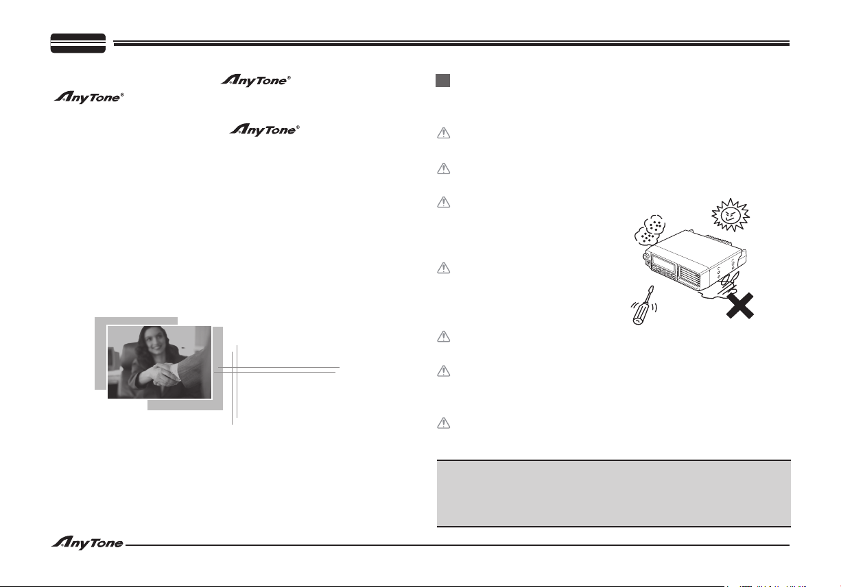
Do not place the transceiver
in excessively dusty, humid
or wet areas, nor on unstable
surfaces.
Please keep it away from
interferential devices (such
as TV, generator etc.) when
interfered by external
Do not expose the transceiver to long periods of direct
sunlight nor place it close to heating appliances.
If an abnormal odor or smoke is detected coming from the
transceiver, turn OFF the power immediately. Contact a
Anytone service station or your dealer.
Do not transmit with high output power for extended periods;
the transceiver may overheat.
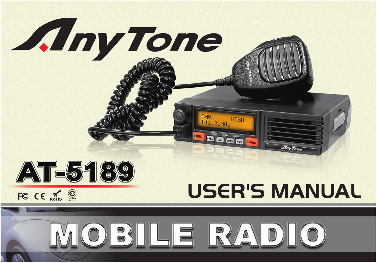
Models Apply To This Manual: AT-5189 Mobile radio
AT-5189 Mobile Radio Applicable Software: QPS589
ATTENTION:
When programming the transceiver, read the factory
initial data first, then rewrite the frequency, otherwise
errors may occur.
Page 3
CONTENTS
SUPPLIED ACCESSORIES/OPTIONAL ACCESSORIES .................. 1
PREPARATION .................................................................................... 2
Mobile Installation ............................................................................ 2
DC Power Cable Connection........................................................... 3
Mobile Operation .......................................................................... 3
Fixed Station Operation ................................................................ 4
Replacing Fuses ........................................................................... 4
Antenna Connection ........................................................................ 5
Accessories Connections ................................................................ 6
External Speaker .......................................................................... 6
Microphone ................................................................................... 6
PC Connection ............................................................................. 6
GETTING ACQUAINTED ..................................................................... 7
Front Panel ...................................................................................... 7
Rear Panel....................................................................................... 8
Microphone ...................................................................................... 8
WORKING MODE ................................................................................ 9
OPERATING BASICS .........................................................................10
Switching The Power On/Off .......................................................... 10
Adjusting The Volume .....................................................................10
Switching The Working Mode .........................................................10
Selector Knob Adjusting Frequency/Channel .................................10
Squelch Off / Squelch Off Momentary ............................................10
Receiving ........................................................................................10
Transmitting .................................................................................... 11
Transmitting Tone-Pulse ................................................................. 11
Transmitting Optional Signaling ......................................................11
SHORTCUT OPERATIONS ................................................................12
Channel Edit ...................................................................................12
Channel Copy .................................................................................12
Channel Delete ..............................................................................12
Channel Name Edit .......................................................................13
Short Call ........................................................................................13
Frequency/Channel Scan ...............................................................13
CTCSS/DCS Scan..........................................................................13
Priority Monitor ...............................................................................14
High/Mid/Low Power Switch (Shortcut) .......................................... 14
Offset Direction Setup (Shortcut) ....................................................14
Wide/Narrow Band Setup (Shortcut) .............................................. 15
Compander Function (Shortcut) .................................................... 15
Reverse Function (Shortcut)...........................................................15
Pre-stored DTMF Code Searching and Transmitting ..................... 15
Scan Channel Skip .........................................................................16
CHANNEL OPERATIONS .................................................................17
CTCSS/DCS Encode Setup ........................................................... 17
CTCSS/DCS Decode Setup ...........................................................17
Add Or Cancel DTMF/2-Tone/5-Tone Signaling .............................17
Choose To Transmit 2-Tone ............................................................18
Choose To Transmit 5-Tone ...........................................................18
Signaling Combination Setup ......................................................... 19
Offset Direction Setup ....................................................................19
Offset Frequency Setup ..................................................................20
Frequency Step Size Setup ............................................................20
Wide/Narrow Band Setup ...............................................................20
Frequency Reverse Setup ..............................................................20
Page 4

CONTENTS
Talk Around .....................................................................................21
High/Mid/Low Power Switch .........................................................21
TX Off Setup ...................................................................................21
Compander (Reduce noise, Improve communication quality) ........ 21
Scrambler Setup( Encryption) Optional .........................................22
BACKGROUND OPERATIONS ..........................................................23
Voice Prompt ..................................................................................23
TOT (Time-out Timer) .....................................................................23
APO (Auto Power Off) ................................................................... 23
Busy Channel Lockout....................................................................24
DTMF Transmitting Time Setup ......................................................24
Squelch Setup ................................................................................ 24
Scan Dwell Time Setup .................................................................. 25
LCD Backlight Setup ......................................................................25
Current Voltage Display ..................................................................26
Choose Tone-Pulse Frequency ......................................................26
DTMF ANI On/Off ...........................................................................26
Display Mode Setup .......................................................................26
Resume Factory Default .................................................................27
MICROPHONE OPERATIONS .......................................................28-29
Key Lock .........................................................................................28
Transmitting DTMF Tone By Microphone .......................................28
Function Setup By Microphone Keyboard ......................................28
AUXILIARY FUNCTIONS ................................................................... 30
Initial Setup .....................................................................................30
Cable Cloning .................................................................................30
Programming Software Installing And Starting ...............................30
MAINTENANCE ..................................................................................31
TROUBLE SHOOTING .......................................................................32
SPECIFICATIONS ...............................................................................33
Page 5
SUPPLIED ACCESSORIES/OPTIONAL ACCESSORIES
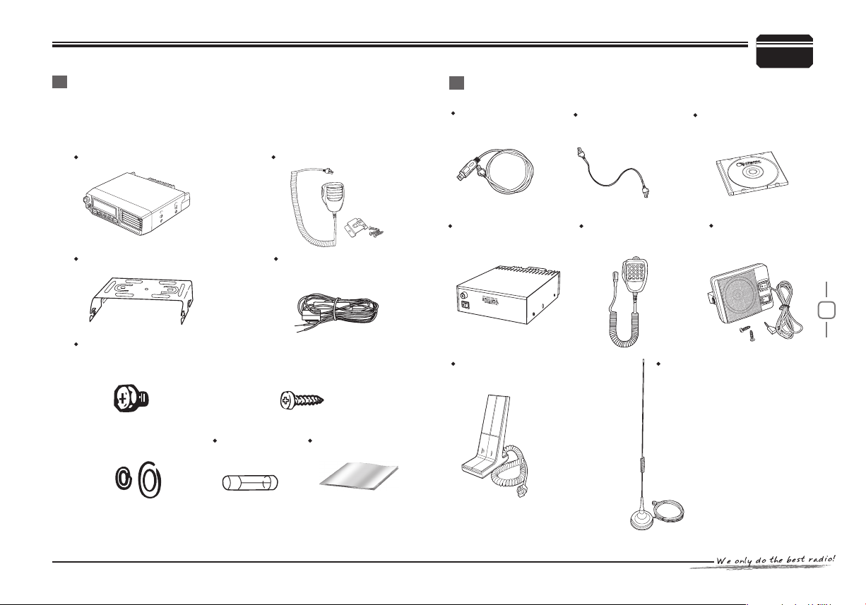
Supplied Accessories
After carefully unpacking the transceiver, identify the items listed in
the table below. We recommend you keep the box and packaging for
shipping.
AT-5189 Vehicle transceiver Microphone (QHM-02)
Optional Accessories
Programming
cable (PC51)
Cloning cable
(CP51)
1
Programming
software (QPS589)
Mounting bracket (QMB-02)
Hardware kit for bracket
Hexagon SEMS screws
(M4x8mm) 4pcs (QSS-02A)
Flat washers / Spring
washers (QSS-02D)
DC power cable with
fuse holder (QPL-02)
Self -Tapping screws
(M5x20mm) 4pcs (QSS-02B)
Spare fuses
2pcs(QF-02)
Instruction manual
Regulated power
supply (QRP-01)
Desktop Microphone
(QDM-01)
DTMF Microphone
(QHM-04)
Car antenna
(QCA-01)
External Speaker
(SP-01)
1
Page 6
2
PREPARATION
2
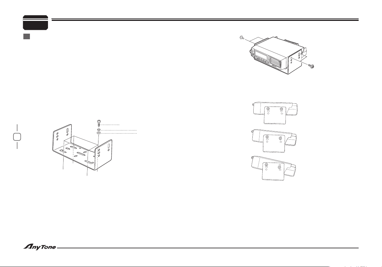
Mobile installation
To install the transceiver, select a safe, convenient location inside
your vehicle that minimizes danger to your passengers and yourself
while the vehicle is in motion. Consider installing the unit at an appropriate position so that knees or legs will not strike it during sudden braking of your vehicle. Try to pick a well ventilated location that is shielded
from direct sunlight.
Install the mounting bracket in the vehicle using the supplied self-1.
tapping screws (4pcs), at washers (4pcs), and spring washers
(4pcs).
The bracket must be installed so that the 3 screw hole positions •
on the side of the mounting bracket are towards the rear of
the bracket.
Self-tapping screw (5mmX16mm)
Spring washer
Position the transceiver, then insert and tighten the supplied 2.
hexagon SEMS screws and at washers.
Double check that all hardware is tightened to prevent vehicle •
vibration from loosening the bracket or transceiver.
Flat washer
Determine the appropriate angle of the transceiver, using the •
3 screw hole positions on the side of the mounting bracket.
Page 7
3
DC Power Cable Connection
Note:
Locate the power input connector as close to the transceiver as
possible.
Mobile Operation
♦
The vehicle battery mu st have a nominal rating of 12 V. Never
connect the transceiver to a 24 V battery. Be sure to use a 12V
vehicle battery that has sufficient current capacity. If the current
to the transceiver is insufficient, the display may darken during
transmission, or transmit output power may drop excessively.
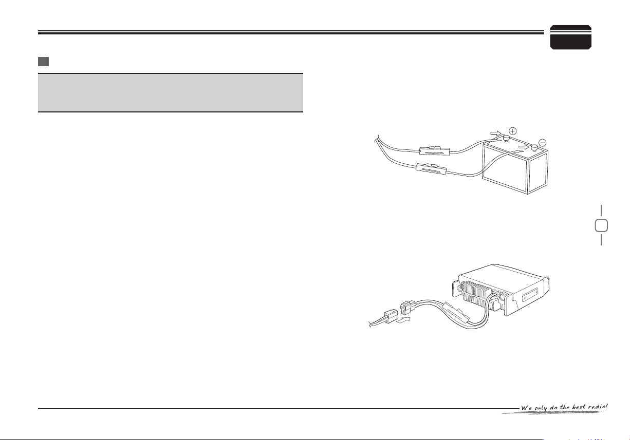
Route the DC power cable supplied with the transceiver directly to 1.
the vehicle's battery terminals using the shortest path from the
transceiver.
If using a noise filter, it should be installed with an insulator •
to prevent it from touching metal on the vehicle.
We recommend you do not use the cigarette lighter socket as som e •
cigarette lighter sockets introduce an unacceptable voltage
drop.
The entire length of the cable must be dressed so it is isolated •
from heat, moisture, and the engine secondary (high voltage)
ignition system/ cables.
After the cable is in place, wrap heat-resistant tape around the 2.
fuse holder to protect it from moisture and tie down the full run of
cable.
To prevent the risk of short circuits, disconnect other wiring from 3.
the negative (-) battery terminal before connecting the transceiver.
PREPARATION
Confirm the correct polarity of the connections, then attach the 4.
power cable to the battery terminals; red connects to the positive (+)
terminal and black connects to the negative (-) terminal.
Use the full length of the cable without cutting off excess •
even if the cable is longer than required. In particular, never
remove the fuse holders from the cable.
Red
Black
Reconnect any wiring removed from the negative terminal. 5.
Connect the DC power cable to the transceiver's power supply 6.
connector.
Press the connectors firmly together until the locking tab •
clicks.
2
Page 8
4
PREPARATION
2
Fixed Station Operation
♦
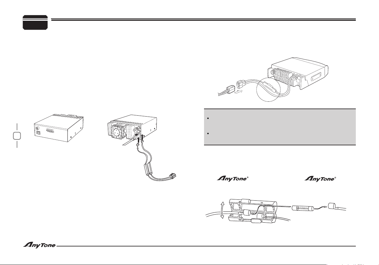
In order to use this transceiver for xed station 1 operation, you will
need a separate 13.8 V DC power supply (not included).
The recommended current capacity of your power supply is 12 A.
Connect the DC power cable to the regulated DC power supply 1.
and ensure that the polarities are correct (Red: positive, Black:
negative).
Do not directly connect the transceiver to an AC outlet. •
Use the supplied DC power cable to connect the transceiver to •
a regulated power supply.
Do not substitute a cable with smaller gauge wires.•
Regulat Power supply [QRP-01]
Black Lead
Red Lead
Connect the transceiver's DC power connector to the connector 2.
on the DC power cable.Press the connectors rmly together until
the locking tab clicks.
Note:
Before connecting the DC power to the transceiver , be sure to
switch the transceiver and the DC power supply OFF.
Do not plug the DC power supply into an AC outlet until you make
all connections.
Replacing Fuses
♦
If the fuse blows, determine the cause, then correct the problem.
After the problem is resolved, replace the fuse. If newly installed fuses
continue to blow, disconnect the power cable and contact your authorized dealer or an authorized service
center for assistance.
Page 9
5
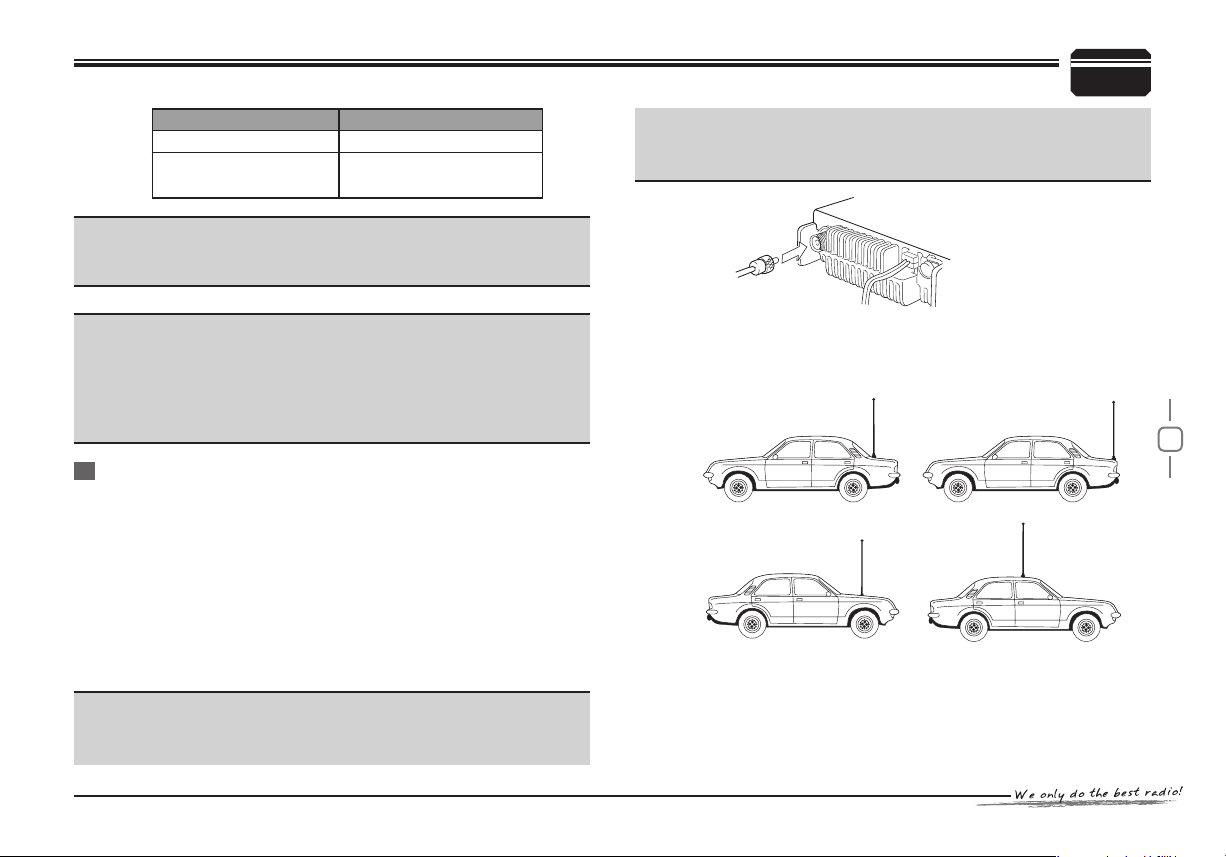
Fuse Location Fuse Current Rating
Transceiver 15A
Supplied Accessory DC
power cable
Caution:
Only use fuses of the specified type and rating; otherwise the
transceiver could be damaged.
Note:
If you use the transceiver for a long period when the vehicle battery
is not fully charged, or when the engine is OFF, the battery may
become discharged, and will not have sufcient reserves to start
the vehicle.
Avoid using the transceiver in these conditions.
20A
Antenna Connection
Before operating, install an efcient, well-tuned antenna. The success
of your installation will depend largely on the type of antenna and its
correct installation. The transceiver can give excellent results if the
antenna system and its installation are given careful attention.
Use a 50Ω impedance antenna and low-loss coaxial feed line that
has a characteristic impedance of 50 Ω, to match the transceiver
input impedance. Coupling the antenna to the transceiver via feed
lines having an impedance other than 50Ω reduces the efciency of
the antenna system and can cause interference to nearby broadcast
television receivers, radio receivers, and other electronic equipment.
Note:
Transmitting without first connecting an antenna or other •
matched load may damage the transceiver. Always connect the
PREPARATION
antenna to the transceiver before transmitting.
All fixed stations should be equipped with a lightning arrester •
to reduce the risk of re, electric shock, and transceiver damage.
The possible locations of antenna on a car are shown as following.
2
Page 10
6
PREPARATION
2
Accessories Connections
External Speaker
♦
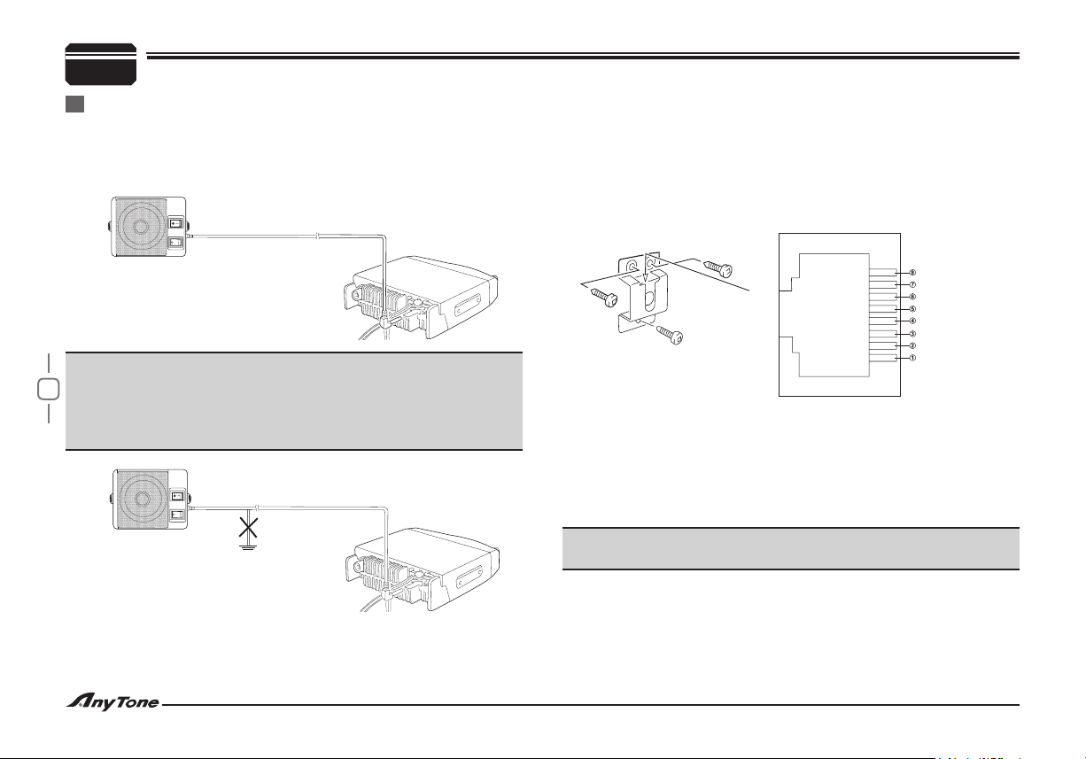
If you plan to use an external speaker, choose a speaker with an
impedance of 8 Ω. The external speaker jack accepts a 3.5 mm (1/8")
mono (2-conductor) plug.
NOISE FILTER
MUTE(-8dB)
SP-01
Note:
External speaker adopt double port BTL, please care about the
connecting way. The speaker can not connect with the ground,
otherwise the speaker will be fault. The wrong connecting way as
the following picture.
NOISE FILTER
MUTE(-8dB)
SP-01
Error
Grond
Microphone
♦
For voice communications, connect a microphone equipped with an
8-pin modular plug into the modular socket on the front of the main
unit. Press rmly on the plug until the locking tab clicks.
Attach the supplied microphone hanger in an appropriate location
using the screws included in the screw set.
Keypad Serial Data
+5V
DOWN
UP
GND(MIC)
MIC
PTT
GND
PC Connecting
♦
To utilize the optional QPS589 software, you must first connect the
transceiver to your PC using an optional programming Cable PC51 (via
the microphone jack).
Please use QPS589 software for programming.
Note:
Ask your dealer about purchasing a Programming Cable PC51.
Page 11
7
GETTING ACQUAINTED
3
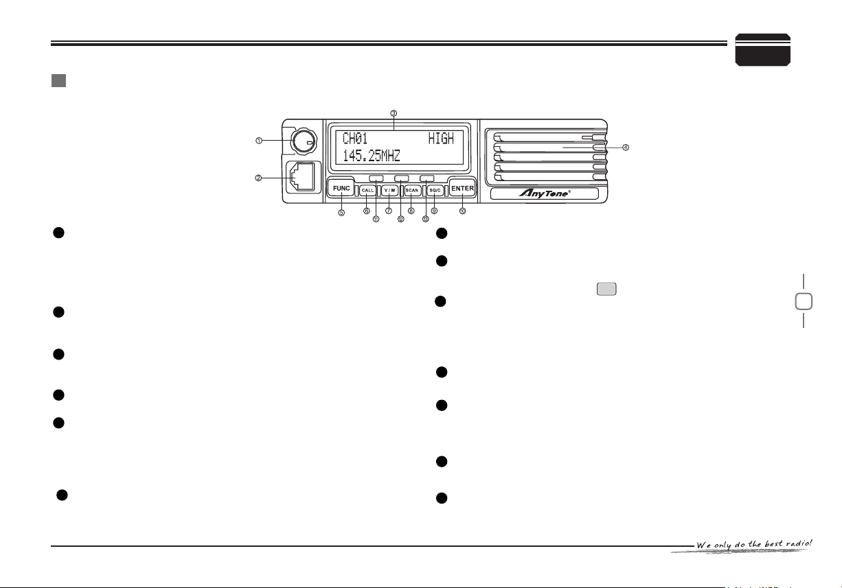
Front Panel
Note: This section describes only the main functions of the front panel controls. Explanations for functions not described here are provided in the
appropriate sections of this instruction manual.
1
Power switch /Volume control/Selector knob
Turn to adjust the frequency/channel while standby.•
Press once while standby and then turn to adjust the volume level.•
Pr ess and hold for 3 s e cond s wh i le s t and b y to swi tch off •
transceiver.
Press once to switch on the transceiver• while switch off.
2
PC/Microphone connection
Standard 8 pins interface for PC programming.•
Connect to microphone for voice communication.•
3
Display LCD
16X2 two rows of dot matrix displaying diversified menus and •
user's information.
4
Speaker
For operating prompting and communication.•
5
FUNC Key
Press it then press relevant key, or press and hold it then within 2 •
seconds press relevant key to achieve multiple shortcut operations.
Pr e ss a n d ho ld m o re t h an 2 sec o nds to e n ter back g roun d •
operations.
CALL Key
6
Press to transmit pre-stored and selected DTMF/2-Tone/5-Tone •
signaling
V/M Key
7
Press to switch between frequency mode and channel mode.•
8
SCAN Key
Repeatedly Press to select• FREQ/CH Scan, CTCSS/DCS Scan,
Priority watch, then press to confirm.
9
SQ/C Key
Press and hold to disable squelch while standby, background noise •
hearable, Release to resume squelch.
Press while in setup mode, transceiver returns to standby and store •
current setups.
10
ENTER key
Press once to enter channel operations setup.•
11
Busy lamp (Green)
Lights while• current channel receives a matching carrier but un-
matching signaling.
Flashes while a matching carrier and signaling received.•
12
Transmitting lamp (Red)
Lights while transmitting.•
13
Power lamp (Yellow)
Lights while power on•
ENTER
Page 12
8
3
Rear Panel
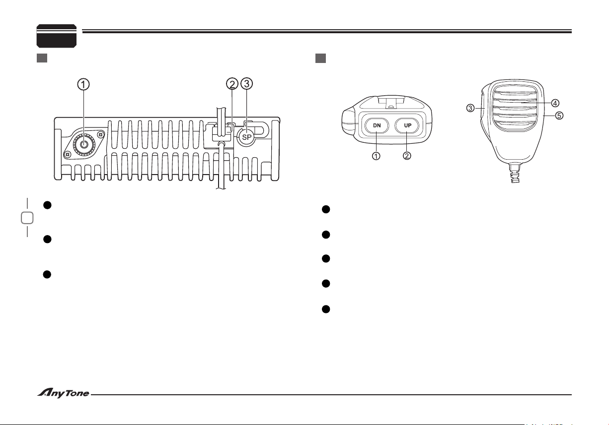
1
Antenna Connector
Connect an external antenna [ page 5] here. When transmitting , •
the antenna system or load should have an impedance of 50 Ω.
2
13.8V DC Cable
Connect a 13.8V DC power source here. Use the supplied DC •
power cable QPL-02 [page 1].
3
SP (Speaker) Jack
If desired, Connec t an optional external spe ak er (SP-01) for •
clearer audio. This jack accepts a 3.5mm(1/8") mono (2-conductor)
plug [page 6]
GETTING ACQUAINTED
Microphone
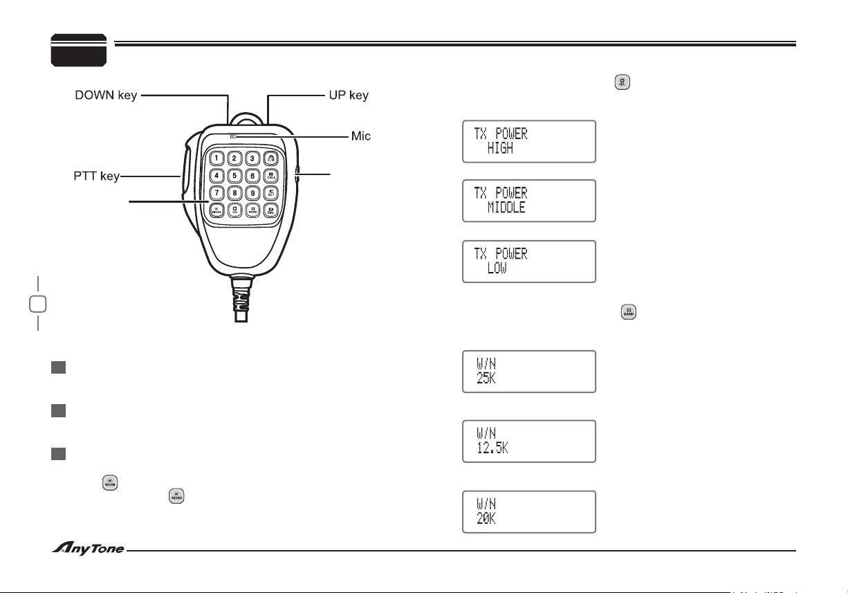
1
DOWN Key
Adjust down in relevant setup.•
2
UP Key
Adjust up in relevant setup.•
3
PTT (Push-To-Talk) switch
Press and hold to transmit . Release to receive•
4
MIC
Speak into microphone • while transmitting.
5
Lock switch
Switch to LOCK position, all Mic keys will invalid except [• PTT].
Page 13
9
WORKING MODE
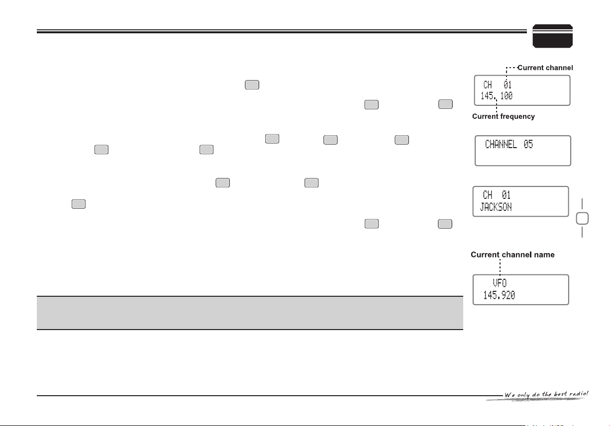
NOTE: This product has 4 working modes and 3 levels of operating menu.
(1) Frequency + channel mode: Under this mode, press key to edit current channel function for temporary use,
temporary channel information will be automatically deleted when power off or change channel.
In this mode, all shortcut setup are temporary change and unable be stored, except press key then press
key to set current channel scan skip.
ENTER
FUNC
SQ/C
4
(2) Channel number mode: Under this mode, invalid to press the key , Press key then press key to channel
scan. Press key then press and hold key for 2 seconds to lock the keyboard.
FUNC
ENTER
ENTER
SCAN
ENTER
All setup in this mode should be operated in PC software , shortcut operations are invalid.
(3) Channel name mode: Under this mode, Press key and then press key to edit current channel name. (The
FUNC
CALL
setup can be stored).
Press key to edit current channel information for temporary use. Temporary channel information will be deleted
ENTER
automatically when power off or change channel.
In this mode, all shortcut setup are temporary change and can’t be stored, except press key then press
FUNC
SQ/C
key to set current channel scan skip.
(4) Frequency mode(VFO): All shortcut operations and channel operations setup will be set as new value and being stored
for long time.
In all modes, background operations can be revised as new value and being stored for long time.
Note:
Frequency + channel mode, Channel number mode, Channel name mode are called channel mode in the
following explanation, individual instruction will be labeled for differentiation.
Three levels of operating menu:1.Shortcut operations menu.
2.Channel operations menu.
3.Background operations menu.
Page 14
10
OPERATING BASICS
5
Switching The Power On/Off
Press the selector knob once to switch on the transceiver while
switch off, Press and hold it for 3 seconds to switch off while standby.
Adjusting The Volume
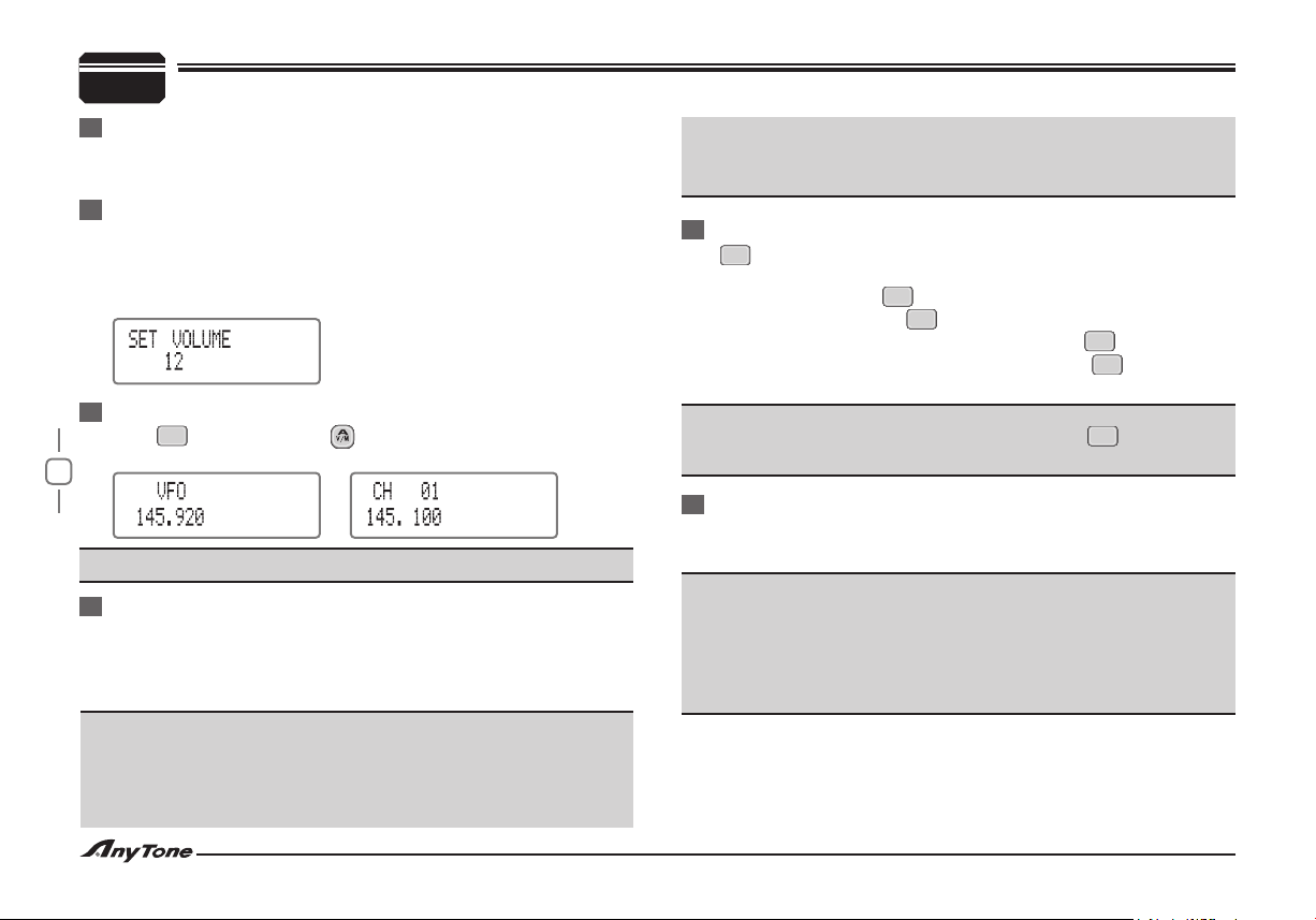
After switch on the transceiver, press the selector knob once, When
LCD displays ”SET VOLUME XX” (XX shows for current volume
level), turn the channel selector knob to adjust volume, Clockwiseup, anticlockwise-down.
Switching The Working Mode
V/M
Press key or Microphone key while standby to switch between
VFO mode and channel mode.
Note: Unavailable while in channel number mode.
Selector Knob Adjusting Frequency/Channel
Under frequency mode, you can change the current frequency to
the desired one through selector knob; Turn clockwise to increase
frequency; turn anticlockwise to decrease. Every gear will increase
or decrease one step.
Note:
5k, 6.25k, 10k, 12.5k, 20k, 25k, 30k, 50k total eight step size
available for this transceiver.
Under channel mode, Turn selector knob clockwise to forward
channel, counterclockwise to backward channel.
In relevant modes ,the Microphone [UP/DWON] key have the same
function of adjusting frequency or edited channel.(this transceiver
shows only edited channels).
Squelch Off / Squelch Off Momentary
SQ/C
key can be set as “Squelch Off / Squelch Off Momentary”
function. This function enable you to monitor weak signal.
Squelch off: Press key once to disable squelch, background 1.
noise appears. Press key again to resume squelch.
Squelch Off Mom en ta ry : Press and hold key to disable 2.
squelch, background noise appears. Release key to resume
SQ/C
SQ/C
SQ/C
SQ/C
squelch.
Note:
The above functions should be set in software, key become a
SQ/C
return key while in function setups.
Receiving
The green LED lamp ashes when the channel being called. then
you can hear the calling from the transmitting party.
Note:
If the transceiver has set with higher squelch level, it may fail to hear
the calling.
If the green lamp keep lighting, it means the transceiver is receiving a
matching carrier and un-matching signaling. The calling is not audible.
( Please refer to signaling combination setup).
Page 15
11
Transmitting
According to different setup of key, press and hold key to
monitor for a while to confirm the channel desired is not busy.
Then, press and hold [PTT] key to speak into microphone.
Please hold the microphone approximately 2.5-5.0cm from your
lips, and then speak into the microphone in your normal speaking
voice to get best timbre.
Note:
Press and hold [PTT] key, LED lights RED indicating it is transmitting, Release to receive.
SQ/C SQ/C
Transmitting Tone-Pulse
Press and hold [PTT], then press Microphone [DOWN] key to
transmit current selected tone-pulse signal.
Transmitting Optional Signaling
Press and hold [PTT], then press Microphone [UP] key to transmit
pre-stored and selected DTMF, 2Tone, 5Tone signaling.
OPERATING BASICS
5
Page 16
12
SHORTCUT OPERATIONS
6
Channel Edit
Under frequency mode (VFO), turn channel selector knob to select 1.
the desired frequency.
ENTER
Press key to start channel function setup and set desired 2.
channel function.(Please refer to channel operations)
FUNC
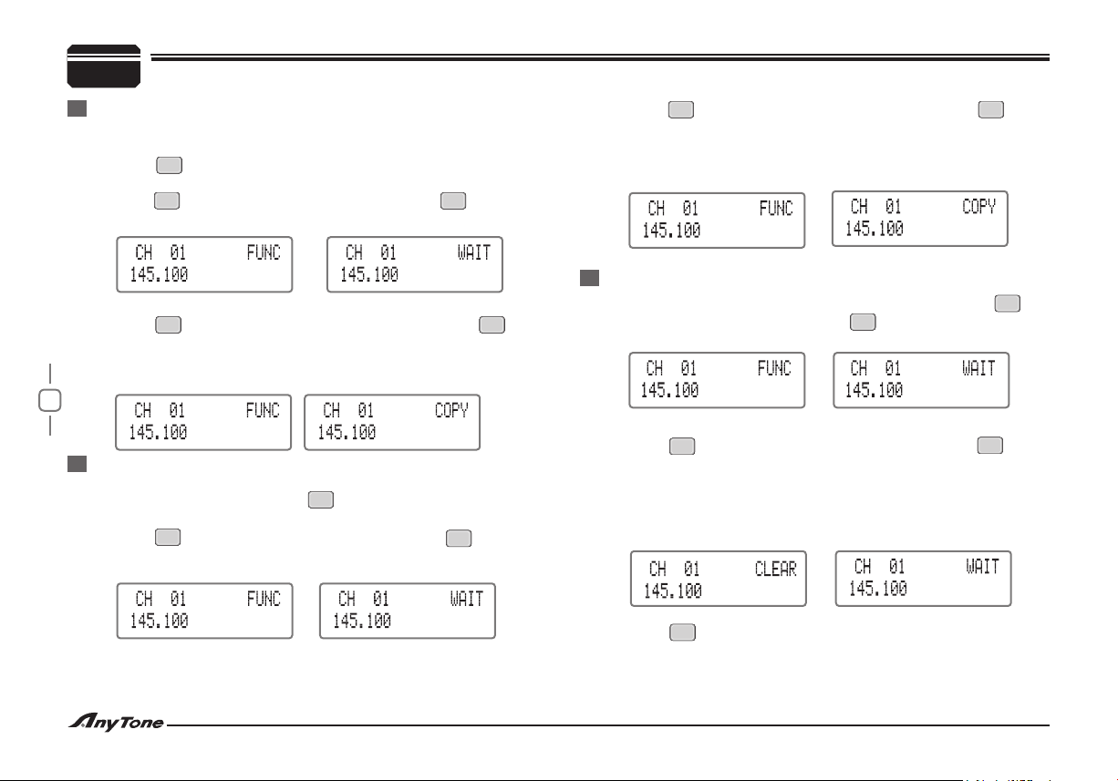
Press key, LCD displays "3. FUNC", then press key, LCD
displays "WAIT"
Turn selector knob to select the desired channel address to store.4.
FUNC
Press key, LCD displays “5. FUNC”, press and hold key
for 2 seconds, LCD displays “COPY” and the transceiver emits
“Du Du"sound, when “COPY” disappears,the channel storage
succeed.
Channel Copy
Copy current channel data to another channel.
Under frequency mode, press key to enter channel mode, turn 1.
selector knob to select the desired copied channel.
FUNC
Press key, LCD displays “2. FUNC”, then press key, LCD
displays “WAIT”
FUNC
Press key, LCD displays “4. FUNC” , press and hold key for
V/M
2 seconds, LCD displays“COPY” and the transceiver emits“Du
Du” sound, when “COPY” disappears, the channel copy
succeed.
V/M
Channel Delete
Under frequency mode (VFO) or channel mode, press key, 1.
V/M
LCD displays "FUNC", then press key. LCD displays "WAIT".
V/M
Turn selector knob to select channel which you want to delete.2.
FUNC
Press key, LCD displays “3. FUNC”, press and hold key for
2 seconds, LCD displays “CLEAR” and the transceiver emits
“Du Du” sound, when “CLEAR” disappears, the channel has
V/M
been deleted. The LCD still displays “WAIT”, and no frequency
displays in current channel.(Repeat step2, 3 to delete channels
V/M
continuously.)
FUNC
CALL
Turn selector knob to select the desired address to store the 3.
copied channel information.
SQ/C
Press key to exit.4.
Page 17
13
Channel Name Edit
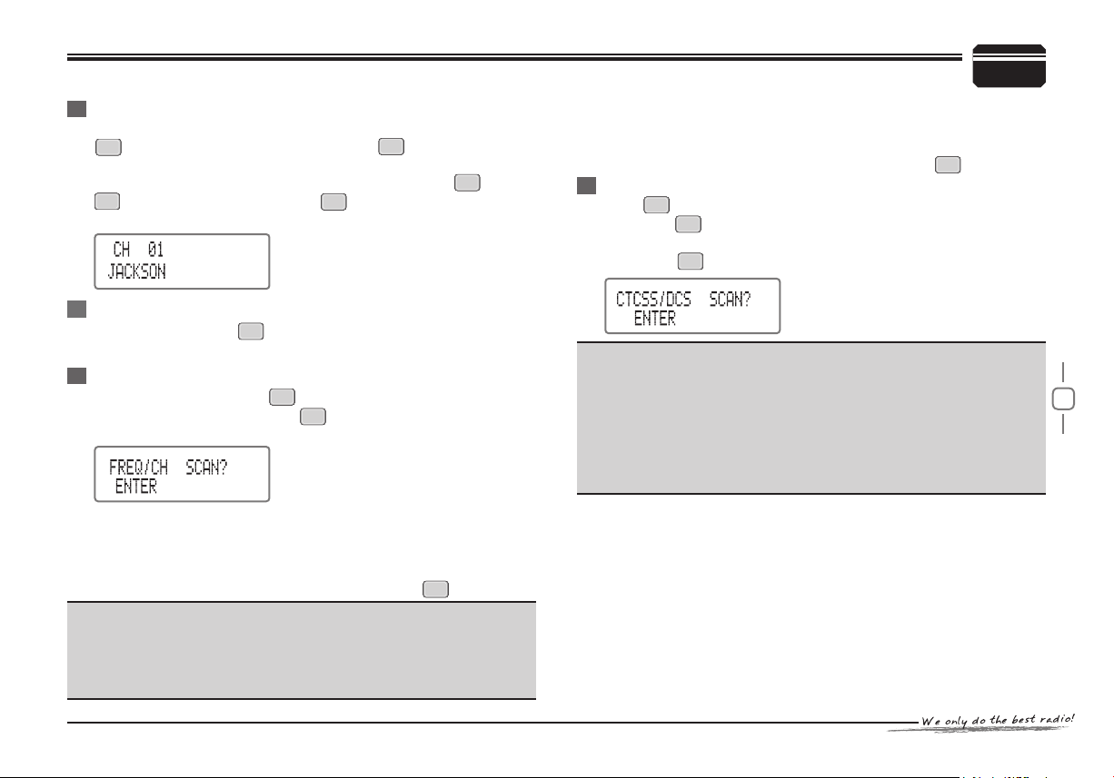
When transceiver is in channel name display mode, after pressing
FUNC
key, LCD displays "FUNC", then press key to get into the
channel name program mode of current channel. Turn ch annel
selector to select the desired character or gure, press key and
V/M
key to move the cursor, press key to conrm and exit when
SQ/C
nish program.
CALL
CALL
Short Call
While standby, press key to transmit optional signaling(DTMF,
2-Tone, 5-Tone) in current channel.
CALL
Frequency/Channel Scan
In relevant modes, press key repeatedly until LCD displays
"FREQ/CH SCAN?", then press key to enable frequency/channel
scan.
Frequency Scan
♦
In frequency mode, this function is designed to monitor signal
of every communicative frequency point of transceiver “STEP”
you have set. Press Microphone [UP/DOWN] or selector knob to
change scan direction, press any key (other than key) to exit.
Note:
When the transceiver is programmed with PA frequency and PB
frequency, in frequency mode (VFO), frequency subsection scan
is valid. For details, please refer to help options in programming
software.
SCAN
ENTER
FUNC
SHORTCUT OPERATIONS
Channel Scan
♦
In channel mode, this function is designed to monitor signal in every
channel. Press Microphone [UP/DOWN] or the selector knob to
change scan direction, press any key (other than key) to exit.
FUNC
CTCSS/DCS Scan
FUNC
Press key repeatedly until LCD displays "CTCSS/DCS SCAN?",
then press key to start scan. When nding a matching signaling,
the scan will pause for 15 seconds then scan again. Press any key
(other than key) to exit.
Note:
Invalid when no signaling existed in current channel.
When the current channel signaling is set to CTCSS, the transceiver will scan CTCSS.
When the current channel signaling is set to DCS, the transceiver
will scan DCS.
Press Microphone [UP/DOWN] or turn selector knob to change scan
direction.
ENTER
FUNC
6
Page 18
14
SHORTCUT OPERATIONS
6
Priority Monitor
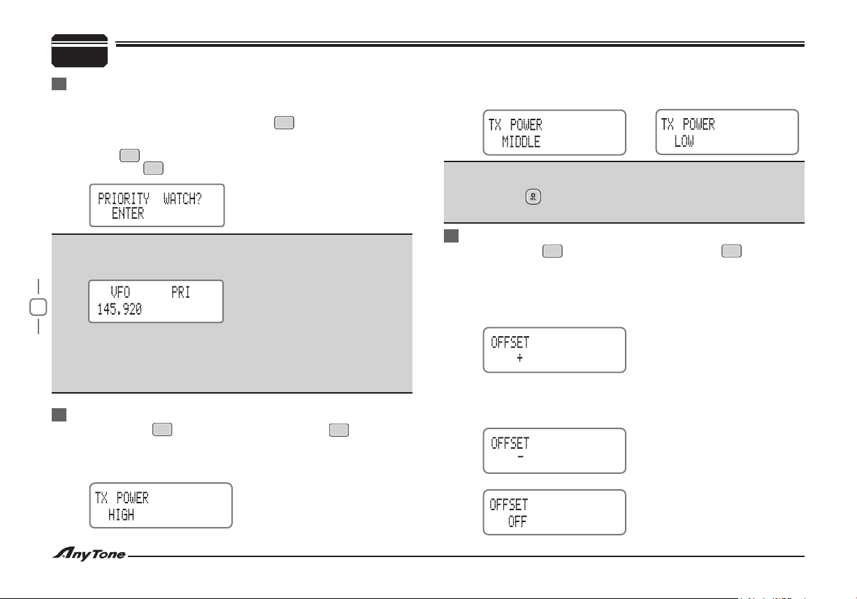
Enable this function in frequency mode(VFO), the transceiver will
detect the signaling of priority channel every 5 seconds one time.
While in frequency mode (VFO), press key to switch to channel 1.
mode, then turn selector knob to select desired monitor channel.
SCAN
Press key repeatedly, when “2. PRIORITY WATCH” appears,
then press key to enter priority monitor
ENTER
V/M
"2. TX POWER MIDDLE" indicates you have choose middle TX power.
"3. TX POWER LOW " indicates you have choose low TX power.
Note:
In frequency mode (VFO)/channel mode, you can repeatedly press
Microphone key to switch between high /middle/low TX power.
This operation is invalid in channel number mode.
Note:
The LCD displays "PRI" While in priority monitor, and the frequency
will shift in every 5 seconds.
When the priority channel receives a matching carrier and signaling,
it will pause for 10 seconds. If press PTT during this time, the dual
watch will stop and the transceiver start communication by current
receiving frequency.
High/Mid/Low Power switch (Shortcut)
Press and hold key while standby, then press key within 2
seconds to switch between high/middle/low power. Repeat this
operation, the LCD displays:
"1. TX POWER HIGH" indicates you have choose high TX power.
FUNC
CALL
Offset Direction (Shortcut)
Press and hold key while standby, then press key within 2
FUNC
seconds to switch offset direction. Repeat this operation, the LCD
displays:
“1. OFFSET+” indicates transmitting frequency is higher than
receiving frequency, if reverse function is enabled, transmitting
frequency will lower than receiving frequency.
“2. OFFSET-” indi cat es tra nsm itt ing fr equ enc y i s l owe r t han
receiving frequency, if reverse function is enabled, transmitting
frequency will higher than receiving frequency.
"3. OFFSET OFF" indicates shut offset.
V/M
Page 19
15
Wide/Narrow Band Setup (Shortcut)
Press and hold key while standby, then press key within
FUNC
SCAN
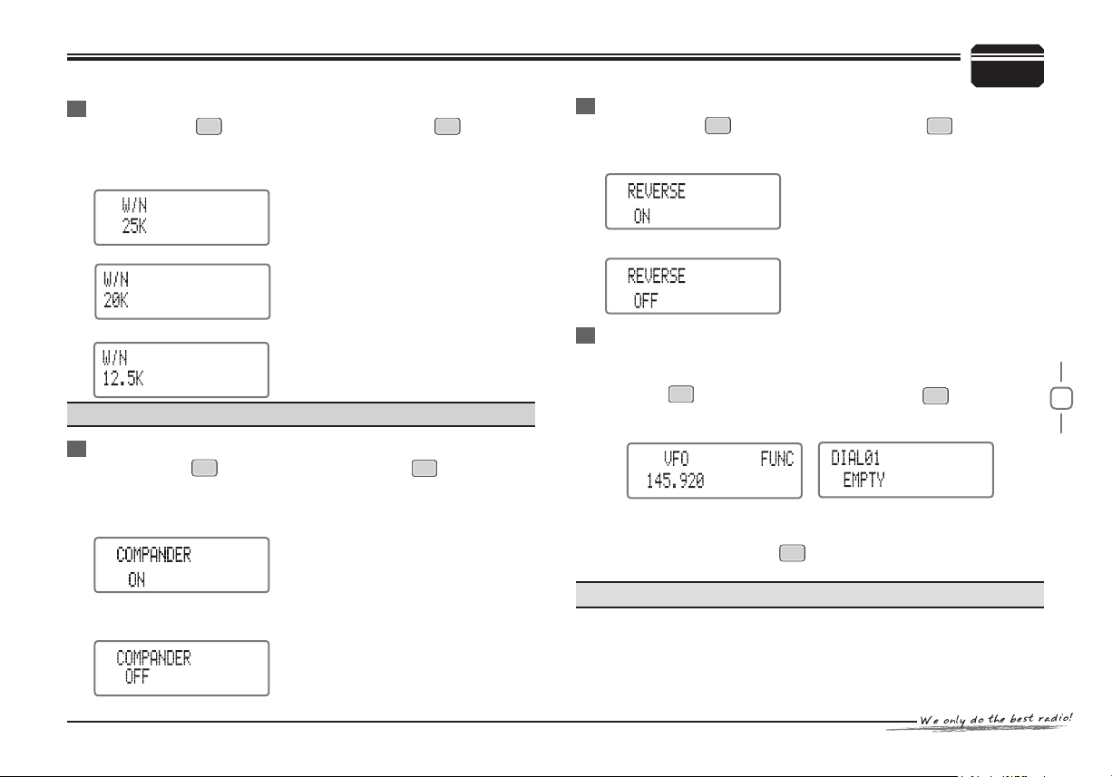
2 seconds to switch bandwidth. Repeat this operation, the LCD
displays.
"W/N 25K" indicates wide bandwidth;
SHORTCUT OPERATIONS
6
Reverse Function (Shortcut)
Press and hold key while standby,then press key to enable
FUNC
or disable reverse function.
LCD displays "REVERSE ON" indicates enable reverse function.
ENTER
"W/N 20K" indicates middle bandwidth;
"W/N 12.5K" indicates narrow bandwidth;
Note:
This operation is invalid in channel number mode.
Compander Function (Shortcut)
Press and hold key while standby , then press key can enable
FUNC
or disable compander function.
LCD displays "COMPANDER ON" indicates enable Compander
function.
LCD displays "COMPANDER OFF" indicates disable Compander
function.
SQ/C
LCD displays "REVERSE OFF" indicates disable reverse function.
Pre-stored DTMF Code Searching and Transmitting
For users convenience, 16 groups of DTMF code can be pre-stored
(Pre-stored DTMF code should be edit by PC program)
Note: This operation is invalid in channel number mode.
FUNC
Press key while standby , then press key to check 1.
SCAN
pre-stored DTMF code, if no signaling in current group, the
transceiver will display "EMPTY".
Turn selector knob or Microphone [2. UP/DOWN] key to check each
group of DTMF code.
Then press [3. PTT] key or key to transmit current group of DTMF
CALL
data.
Page 20
16
6
SHORTCUT OPERATIONS
Scan Channel Skip
FUNC
Press key while in frequency + channel number mode or in
channel name+ channel number mode, when"FUNC"appears, then
SQ/C
press key , repeat above operation to setup current channel be
scanned or not.
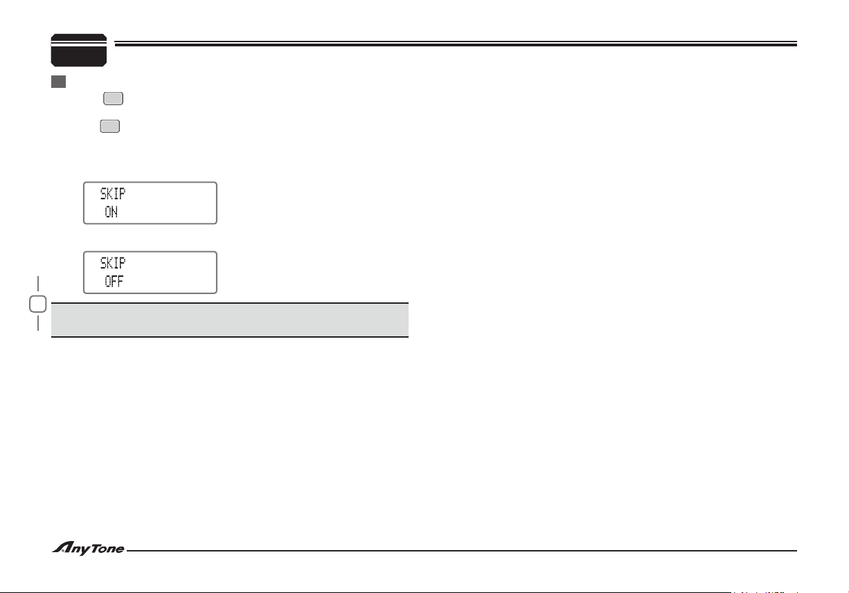
When "1. SKIP ON" appears, indicate the current channel scan be
skipped.
When "2. SKIP OFF" appears, indicate the current channel be scanned.
Note:
This operation is invalid in channel number mode or frequency
mode.
Page 21
17
Under channel mode, channel operations can edit current channel
function for temporary use, when power off or channel has been
changed, the relevant setup will be deleted automatically.
While standby the operations as following.
ENTER
Press key to enter the channel function menu.1.
Repeatedly press key or Microphone [2. UP/DOWN] key to
SCAN
select the menus to be set.
Turn selector knob to choose the selected content.3.
SQ/C
Press key or key to conrm and exit the setup.4.
ENTER
Note:
This operation is invalid in channel number mode. under frequency
mode (VFO), channel operations will be stored for longterm.
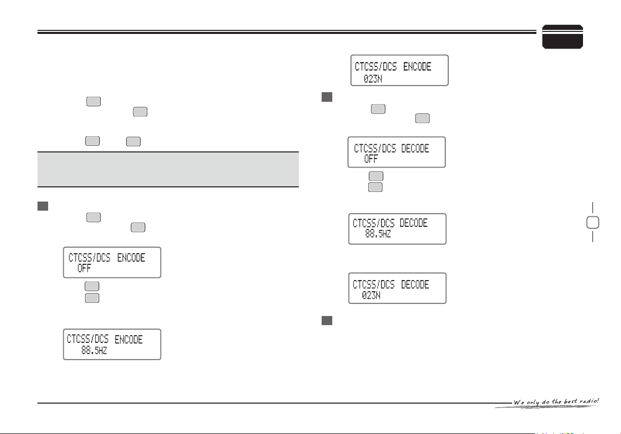
CTCSS/DCS Encode Setup
ENTER
Press key to enter function menu.1.
Repeatedly press key or Microphone [2. UP/DOWN] key until
LCD displays “CTCSS/DCS ENCODE”
CALL
Press key to select CTCSS,DCS or OFF, when DCS selected, 3.
V/M
press key to select positive or inverse code.
Turn selector knob to select desired CTCSS/DCS code.4.
CTCSS code: 62.5Hz-254.1Hz, 51 groups utmost.5.
DCS code: 000N-777I, total 1024 groups, N stands for positive 6.
code, I stands for inverse code. Default :023N
SCAN
CHANNEL OPERATIONS
7
CTCSS/DCS Decode Setup
ENTER
Press key to enter function menu.1.
Repeatedly press key or Microphone [2. UP/DOWN] key until
SCAN
LCD displays “CTCSS/DCS DECODE”.
CALL
Press key to select CTCSS,DCS or OFF, when DCS selected, 3.
V/M
press key to select positive or inverse code.
Turn selector knob to select desired CTCSS/DCS code.4.
CTCSS code: 62.5Hz-254.1Hz, 51 groups utmost.5.
DCS code: 000N-777I, total 1024 groups, N stands for positive 6.
code, I stands for inverse code. Default: 023N
Add Or Cancel DTMF/2-Tone/5-Tone Signaling
DTMF/2-Tone/5-Tone signaling are similar to CTCSS/DCS, while
DTMF and 5-Tone have other special functions including ANI, PTT
ID, Call All, Group Call, Signal Call, Alarm, Remote Stun, Remote
Kill, Wake Up, Tail Eliminating. for more information and setup,
please refer to the help option in the programming software.
Page 22
18
7
CHANNEL OPERATIONS
ENTER
Press key to enter function menu. 1.
Repeatedly press key or Microphone [2. UP/DOWN] key until
SCAN
LCD displays "TONE DECODE".
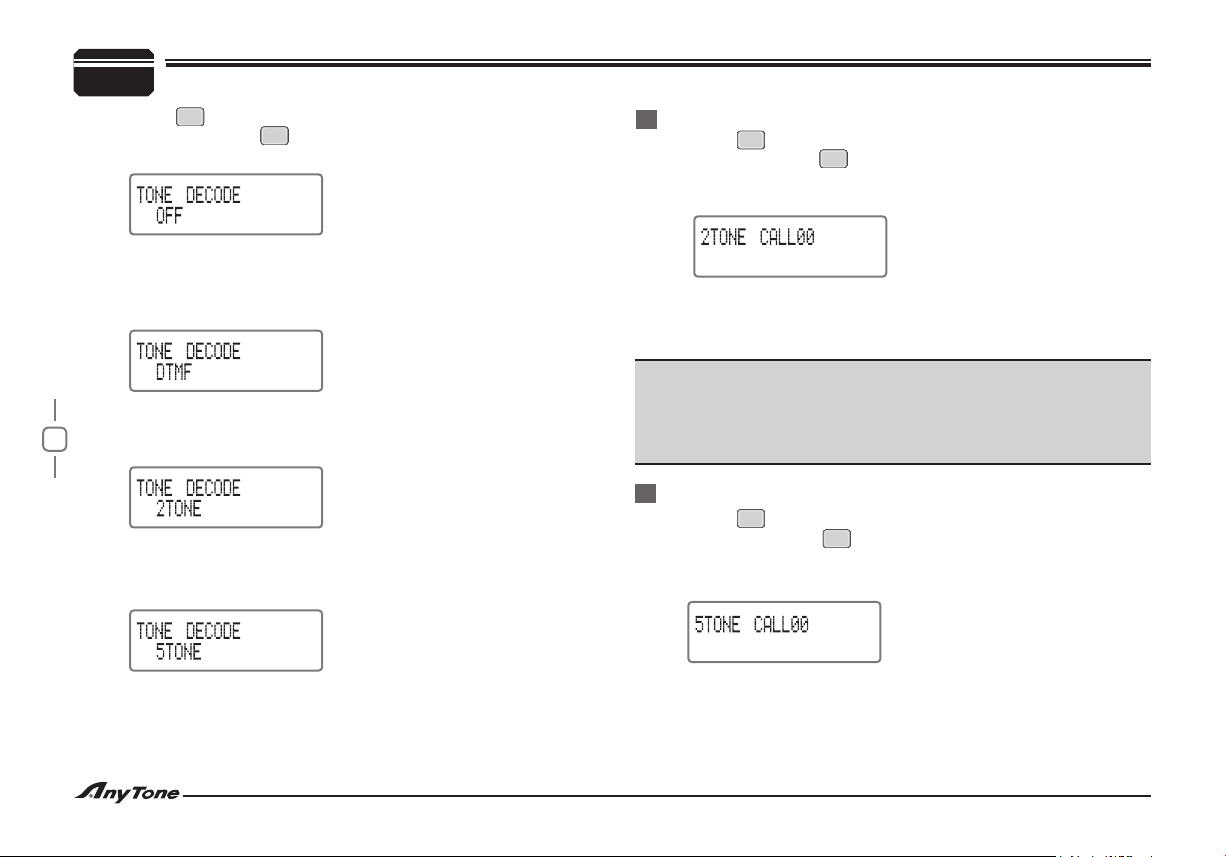
Turn selector knob to select desired setup.3.
When the LCD displays “4. DTMF”, the current channel has
DTM F signaling squelch when receive. Hold [PTT] key then press
UP key to transmit pre-stored and selected DTMF signaling.
When the LCD displays “5. 2TONE”, the current channel has 2-Tone
signaling squelch when receive. Hold [PTT] key then press [UP]
key to transmit pre-stored and selected 2-Tone signaling.
When the LCD displays “6. 5TONE”, the current channel has 5-Tone
signaling squelch when receive. Hold [PTT] key then press [UP]
key to transmit pre-stored and selected 5-Tone signaling.
Choose To Transmit 2-Tone
ENTER
Press key to enter function menu.1.
Repeatedly press key or Microphone [2. UP/DOWN] key until
SCAN
LCD displays "2TONE CALLXX", (XX stands for current group
name).
Turn selector knob to select the desired 2-Tone group, press [3. PTT]
key will transmit current selected group.
In total 32 groups, 00-31 utmost, Default : 004.
Note:
2-Tone setup should be programmed by software, the transceiver
can only display the programmed group. If you edit each group
with a name , the name and number will both displayed when you
check 2-Tone.
Choose To Transmit 5-Tone
ENTER
Press key to enter function menu.1.
Repeatedly press key or Microphone [2. UP/DOWN] key until
LCD displays "5TONE CALLXX", (XX stands for current group
name.)
SCAN
When the LCD displays "7. OFF", DTMF, 2-Tone, 5-Tone signaling are
cancelled.
Turn selector knob to select a 5-Tone group , then press [3. PTT]
key to transmit current selected group.
In total 100 groups, 00-99 utmost, default : 004.
Page 23
19
Note:
5-Tone setup should be programmed by software, the transceiver
can only display the programmed group. If you edit each group with
a name , the name and number will both displayed when you check
5-Tone.
Signaling Combination Setup
This function is used to setup squelch mode.
ENTER
Press key to enter function menu.1.
Repeatedly press key or Microphone [2. UP/DOWN] key until
SCAN
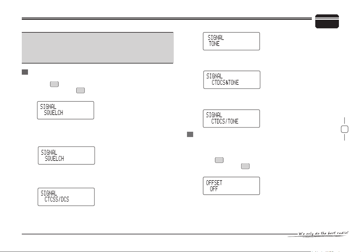
LCD displays "SIGNAL".
CHANNEL OPERATIONS
7
“CTDCS&TONE”, you can here the calling as long as the
transceiver receives a matching carrier and a matching CTCSS or
DCS signaling and a matching DTMF, 2-Tone or 5-Tone signaling.
"CTDCS/TONE", you can here the calling as long as the transceiver receives a matching carrier and any one of a matching
CTCSS,DCS, DTMF,2-Tone,5-Tone signaling.
Turn selector knob to select desired signaling combination. 3.
When LCD Displays:
"SQUELCH" indicates you can hear the calling as long as the
transceiver receives matching carrier.
“CTCSS/DCS” indicates you can hear the calling as long as the
transceiver receives a matching carrier and a matching CTCSS
or DCS signaling.
“TONE” indica tes you can h ear the calli ng as long as t he
transceiver receives a matching carrier and a matching DTMF,
2-Tone or 5-Tone signaling.
Offset Direction Setup
This function should coordinate with the offset frequency setup,
which enable you to communication with another transceiver through
a repeater.
ENTER
Press key to enter function menu.1.
Repeatedly press key or Microphone [2. UP/DOWN] key until
SCAN
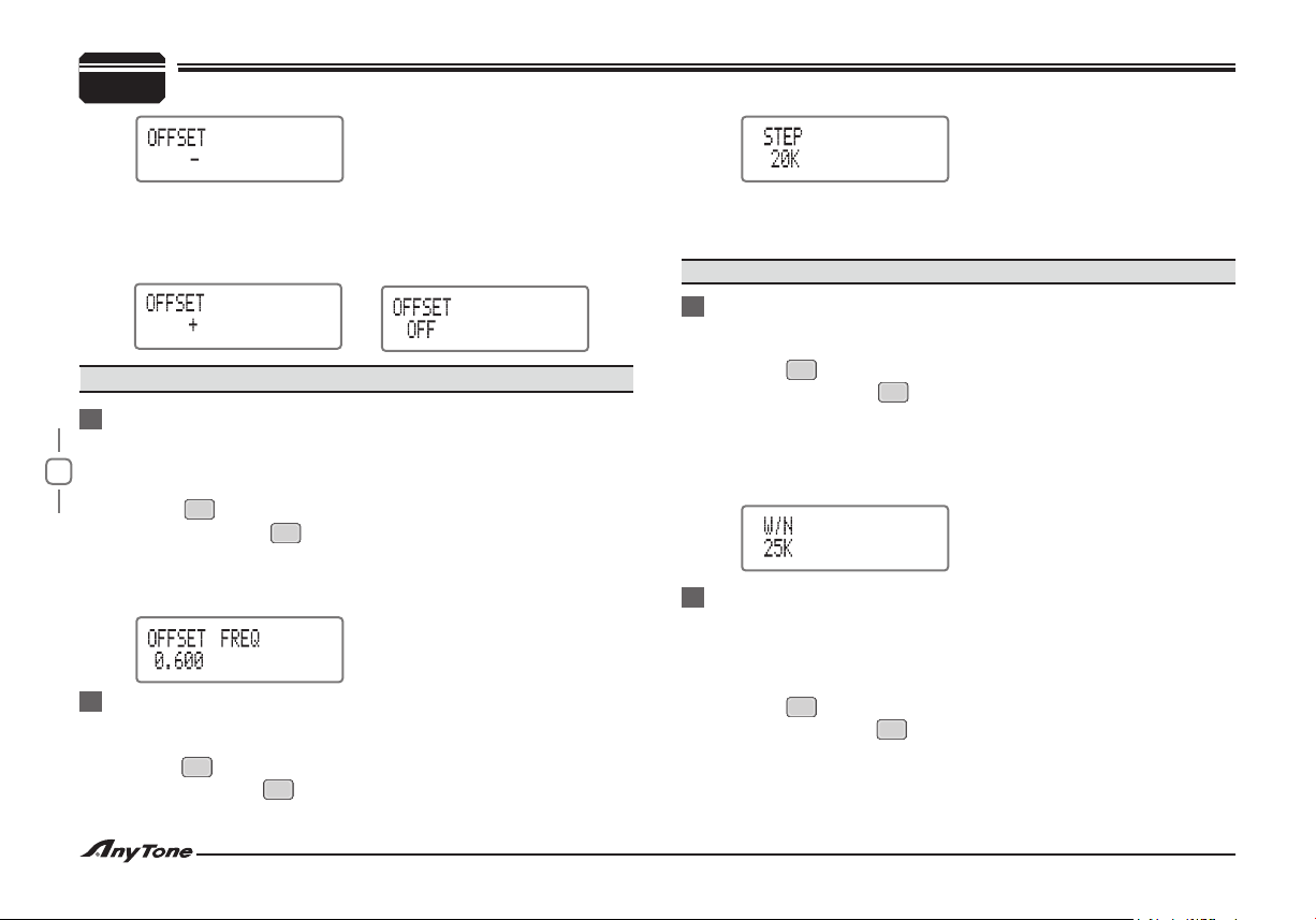
LCD displays "OFFSET"
Turn selector knob to select the desired offset direction.3.
“OFFSET-”, i ndica tes transm itt ing f req uency is l ower than
re cei v ing fre que n cy. Whe n Re ver se F u nct ion is ena b led ,
Transmitting frequency is higher than receiving frequency.
Page 24
20
CHANNEL OPERATIONS
7
“OFFSET+”, indicates transmi tting frequency is h igher than
receiving frequency. if Reverse Function is enabled, Transmitting
frequency will lower than receiving frequency.
“OFFSET OFF” shuts offset direction.
Note:
Invalid when Talk Around function is enabled.
Offset Frequency Setup
This function should coordinate with offset direction setup, which
enable you to communication with another transceiver through a
repeater.
ENTER
Press key to enter function menu.1.
Repeatedly press key or Microphone [2. UP/DOWN] key until
SCAN
LCD displays "OFFSET FREQ".
Turn selector knob to select the desired offset frequency.3.
Offset frequency range: 00-69.995 MHz. Default: 0.6Mhz.4.
Frequency Step Size Setup
Available only in frequency mode (VFO). Adjusting Frequency by
selector or frequency scan is restricted by frequency step size.
ENTER
Press key to enter function menu1.
Repeatedly press key or Microphone [2. UP/DOWN] key until LCD
SCAN
displays "STEP"
Turn selector knob to select the desired step size.3.
Available step size: 5K,6.25K,10K,12.5K,20K,25K,30K,50K.
Default: 20K
Note:
This function is unavailable in channel mode.
Wide/Narrow Band Setup
Select suitable bandwidth in accordance with different local
conditions.
ENTER
Press key to enter function menu.1.
Repeatedly press key or Microphone [2. UP/DOWN] key until
SCAN
LCD displays "W/N".
Turn selector knob to select the desired bandwidth.3.
Option: 25K (Wide band), 20K (Middle band), 12.5K(Narrow band).
Default: 25K.4.
Frequency Reverse Setup
The TX/RX frequency will be reversed when this function is enabled:
TX frequency changes to RX frequency, RX frequency changes to
TX frequency. The signaling will also be reversed if CTCSS/DCS
signaling existed.
ON: enable frequency reverse OFF: disable frequency reverse
ENTER
Press key to enter function menu.1.
Repeatedly press key or Microphone [2. UP/DOWN] key until
SCAN
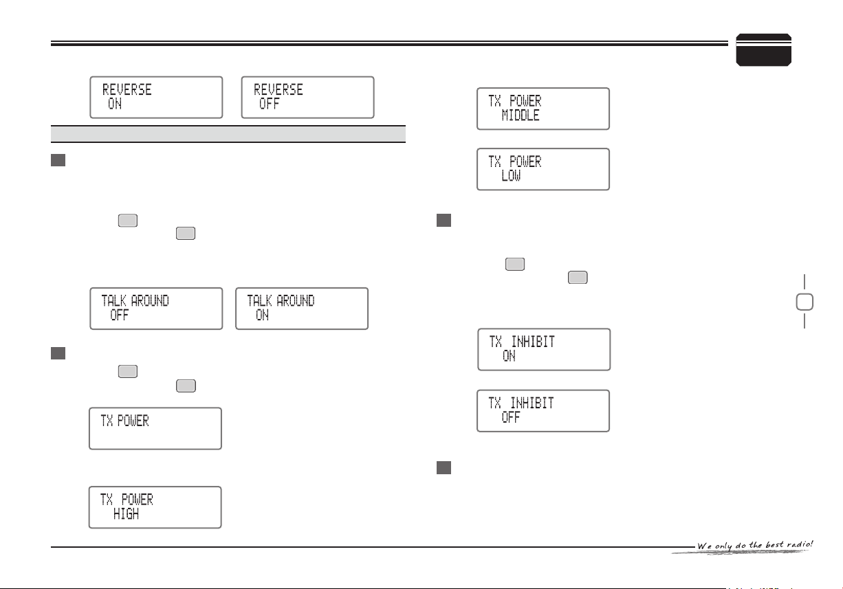
LCD displays "REVERSE".
Turn selector knob to select the desired setup.3.
Page 25
21
Note:
Invalid when talk around function is enabled.
Talk Around
When this function is enabled, The transceiver will secede from
repeater station communication mode and transmitting by receiving
frequency and its CTCSS/DCS signaling.
ENTER
Press key to enter function menu.1.
Repeatedly press key or Microphone [2. UP/DOWN] key until
SCAN
LCD displays "TALK AROUND"
Turn selector knob to select the desired setup.3.
ON: enable talk around. OFF: disable talk around.
Default: OFF4.
High/Mid/Low Power Switch
ENTER
Press key to enter function menu1.
Repeatedly press key or Microphone [2. UP/DOWN] key until
LCD displays "TX POWER"
Turn selector knob to select the desired setup.3.
HIGH: indicates high TX power
SCAN
CHANNEL OPERATIONS
7
MIDDLE: indicates middle TX power
LOW: indicates low TX power
Default: High4.
TX Off Setup
[PTT] is invalid when this function i s enabled, and the cu rrent
channel only works in RX mode.
ENTER
Press key to enter function menu.1.
Repeatedly press key or Microphone [2. UP/DOWN] key until
SCAN
LCD displays "TX INHIBIT".
Turn selector knob to select the desired setup:3.
ON: enable TX OFF function, [PTT] is invalid.
OFF: disable TX OFF function, transmitting enabled.
Default: OFF4.
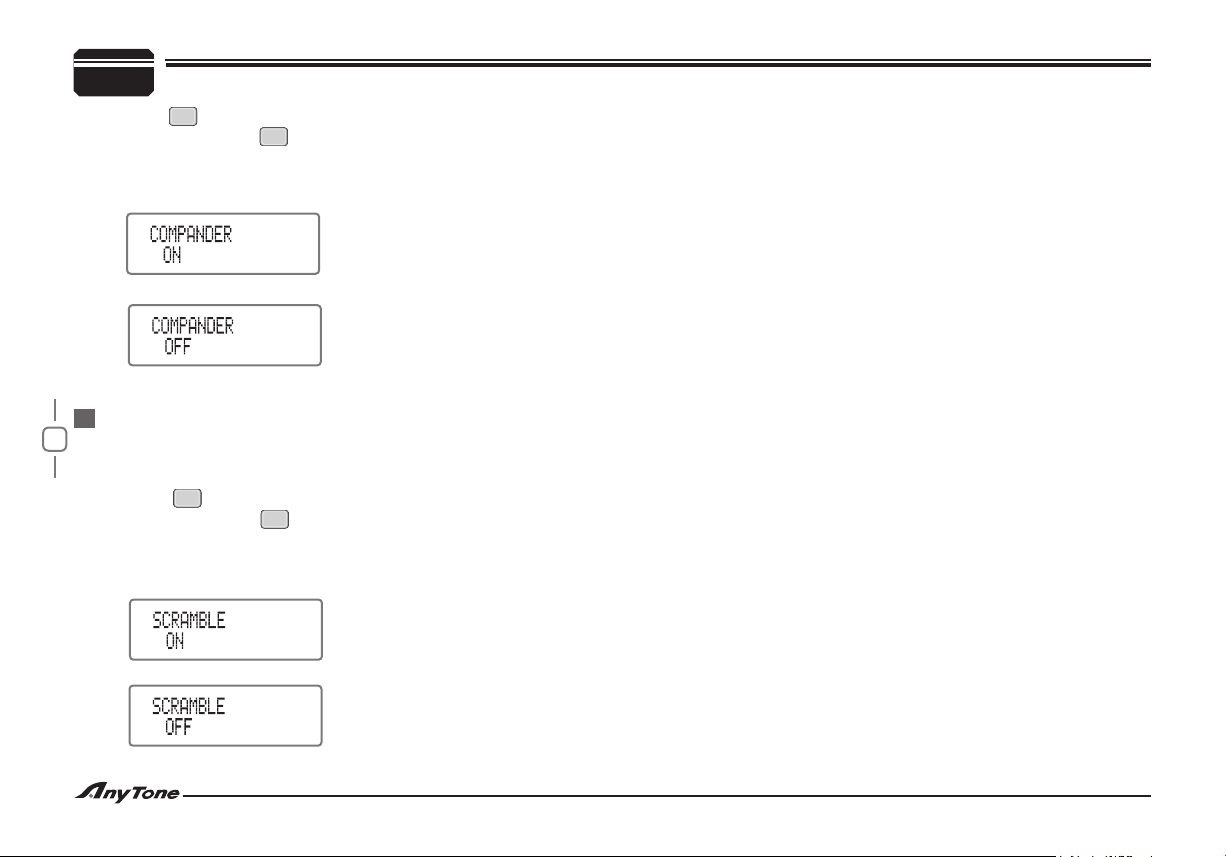
Compander (Reduce noise, Improve communication
Quality)
Enable this function to reduce noise and improve communication
quality, especially in long range communication.
Page 26
22
7
CHANNEL OPERATIONS
ENTER
Press key to enter function menu.1.
Repeatedly press key or Microphone [2. UP/DOWN] key until
SCAN
LCD displays "COMPANDER".
Turn selector knob to select the desired setup:3.
ON: enable compander.
OFF: disable compander.
Default: OFF.4.
Scramble Setup( Encryption) Optional
This special voice processing can offer condential communication,
another transceiver in same frequency can receive only disorder
noises.
ON: enable scramble.
ENTER
Press key to enter function menu.1.
Repeatedly press key or Microphone [2. UP/DOWN] key until
SCAN
LCD displays "SCRAMBLE".
Turn selector knob to select the desired setup:3.
OFF: disable scramble
Default:OFF4.
Page 27
23
Background operations can be changed in any modes, and can be
stored as the latest value for a long time, the operations as following:
Press and hold key for over 2 seconds to enter background 1.
FUNC
operations menu.
Repeatedly press key or Microphone [2. UP/DOWN] key to
SCAN
select desired function option.
Turn selector knob to select desired setup.3.
SQ/C
Press key to conrm selection and to exit.4.
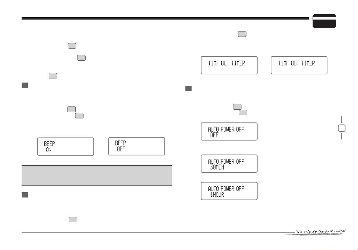
Voice Prompt
The prompting tone provides confirmation of entry, error status or
malfunctions of the transceiver. You can enabled or disable this
function.
Press and hold key for over 2 seconds to enter function menu.1.
Repeatedly press key or Microphone [2. UP/DOWN] key until
LCD displays "BEEP".
Turn selector knob to select the desired setup.3.
ON: enable voice Prompt OFF: disable voice Prompt
Default: ON4.
Note:
We recommend you leave this functi on on i n order t o detec t
erroneous operations and malfunctions.
FUNC
SCAN
BACKGROUND OPERATIONS
Repeatedly press key or Microphone [1. UP/DOWN] key until
SCAN
8
LCD displays "TIME OUT TIMER"
Turn selector knob to select desired setup:2.
ON: enable Time-out timer OFF: disable Time-out timer
Default: OFF4.
APO (Auto power off)
Enable this function, the transceiver will automatically switches off
after working for a scheduled period of time.
Press and hold key for over 2 seconds to enter function menu.1.
Repeatedly press key or Microphone [2. UP/DOWN] key until
LCD displays "AUTO POWER OFF"
Turn selector knob to select desired setup:3.
30MIN: Automatic power off after 30 minutes
1HOUR:Automatic power off after 1 hour
FUNC
SCAN
TOT (Time-out timer)
This function is set to prevent the transceiver from longtime transmitting.
If the continuous transmitting exceeds the programmed time, it will
be pause and an alert tone will sound.
Press and hold key for over 2 seconds to enter function menu.1.
FUNC
2 HOUR: Automatic power off after 2 hours
Default: OFF4.
Page 28
24
8
BACKGROUND OPERATIONS
Busy Channel Lockout
When activated BCL,you can not transmit in busy channel, BCL
prevents you from interfering with other parties who may be using
the same channel that you selected .
Pressing the [PTT] while the chann el is in use w ill cause your
transceiver to emit an alert tone and transmission will be inhibited
and return to receive mode.
Press and hold key for over 2 seconds to enter function menu.1.
Repeatedly press key or Microphone [2. UP/DOWN] key until
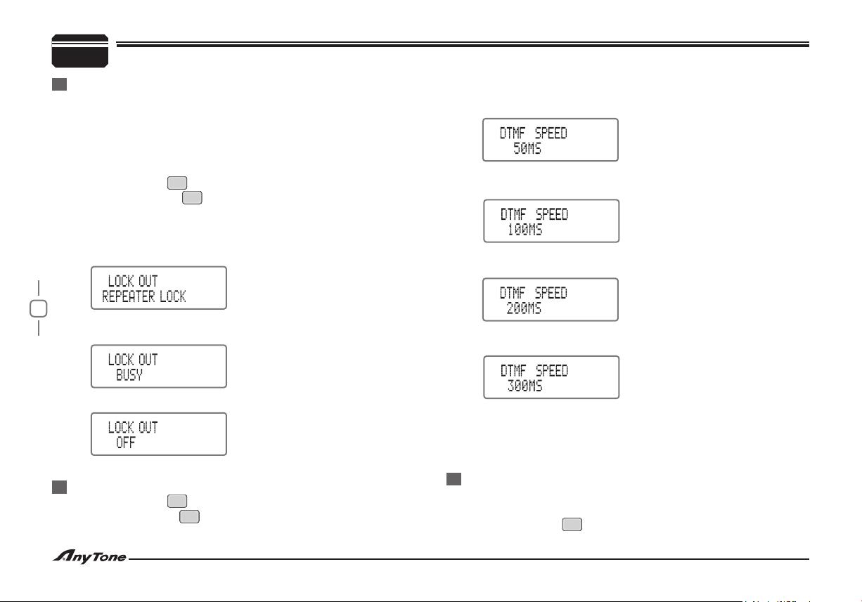
LCD displays "LOCK OUT"
Turn selector knob to select desired setup:3.
REPEATERT LOCK: Transmitting is inhibited when current
channel receives a matching carrier with different CTCSS / DCS.
FUNC
SCAN
Turn selector knob to select desired setup.3.
50MS:Every audio signal of DTMF transmits 50MS and pauses
50MS.
100MS:Every audio signal of DTMF transmits 100MS and pauses
100MS.
200MS:Every audio signal of DTMF transmits 200MS and pauses
200MS.
BUSY: Carrier busy lock, transmitting is inhibited when current
channel receives a matching carrier.
OFF: BCL disables.
Default: OFF4.
DTMF Transmitting Time Setup
Press and hold key for over 2 seconds to enter function menu.1.
Repeatedly press key or Microphone [UP/DOWN] key until
LCD displays "DTMF SPEED".
FUNC
SCAN
300MS:Every audio signal of DTMF transmits 300MS and pauses
300MS.
500MS:Every audio signal of DTMF transmits 500MS andpauses
500MS
Default: 100MS4.
Squelch Setup
The purpose of Squelch is to mute the speaker when no signals are
present.
Press and hold key for over 2 seconds to enter function menu.1.
FUNC
Page 29
25
Repeatedly press key or Microphone [1. UP/DOWN] key until
SCAN
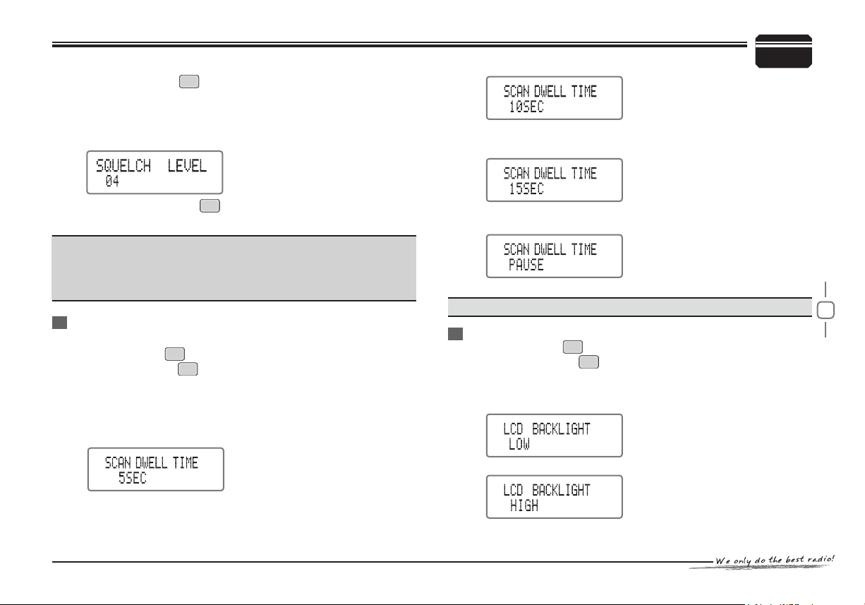
LCD displays "SQUELCH LEVEL".
Turn selector knob to select the desired level2.
00-20: Total 21 levels available; 00: Minimum ~ 20:Maximum3.
Default: 044.
BACKGROUND OPERATIONS
8
15SEC: scan pause for 15 seconds when search a matching signal,
then continue to scan.
Remind : Press and hold key, then turn selector knob also can
SQ/C
adjust the squelch level.
Note:
If the squelch level is too high, the transceiver will fail to get weak
signal; if the squelch level is too low, the transceiver will be easily
disturbed.
Scan Dwell Time Setup
Four types of scan dwell time available.
Press and hold key for over 2 seconds to enter function menu.1.
Repeatedly press key or Microphone [2. UP/DOWN] key until
LCD displays "SCAN DWELL TIME".
Turn selector knob to select desired setup:3.
5SEC: scan pause for 5 seconds when search a matching signal,
then continue to scan.
10SEC: scan pause for 10 seconds when search a matching signal,
then continue to scan.
FUNC
SCAN
Pause: Scan pause when search a matching signal , Continue to
scan after signal disappears 2 seconds.
Default: 15SEC5.
Note:
This setup can be also applied in CTCSS/DCS scan.
LCD Backlight
Press and hold key for over 2 seconds to enter function menu.1.
Repeatedly press key or Microphone [UP/DOWN] key until
FUNC
SCAN
LCD displays "LCD BACKLIGHT".
Turn selector knob to select desired setup.2.
LOW: Low brightness
HIGH: High brightness
Default: HIGH4.
Page 30
26
8
BACKGROUND OPERATIONS
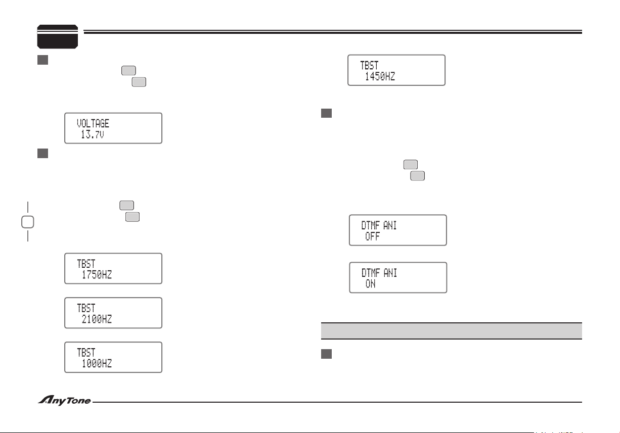
Current Voltage Display
Press and hold key for over 2 seconds to enter function menu.1.
Repeatedly press key or Microphone [UP/DOWN] key until
LCD displays "VOLTAGE".
The LCD will show current voltage.2.
FUNC
SCAN
Choose Tone-Pulse Frequency
This function is used to start the repeater; it needs a certain intensity
of Tone-pulse single to start the sleep repeater. Usu al ly when
repeater has started, repeater system does not require this Tonepulse.
Press and hold key for over 2 seconds to enter function menu.1.
Repeatedly press key or Microphone [UP/DOWN] key until LCD
displays "TBST".
Turn selector knob to select desired setup:2.
1750Hz: Tone-burst frequency is 1750Hz;
2100Hz: Tone-burst frequency is 2100Hz;
1000Hz: Tone-burst frequency is 1000Hz;
FUNC
SCAN
Default: 1750Hz4.
DTMF ANI On/Off
ANI function is available through DTMF signaling or 5-Tone signaling.
Enable this function to realize DTMF ANI function, the transceiver
will display the caller's ID number when it receives a DTMF ANI
calling.
Press and hold key for over 2 seconds to enter function menu.1.
Repeatedly press key or Microphone [2. UP/DOWN] key until LCD
displays "DTMF ANI".
Turn selector knob to select desired setup:3.
OFF: DTMF ANI function off
ON: DTMF ANI function on
Default: OFF4.
Use software to set up 5-Tone ANI function.
Note:
Use software to set up DTMF ANI function.
FUNC
SCAN
1450Hz: Tone-burst frequency is 1450Hz:
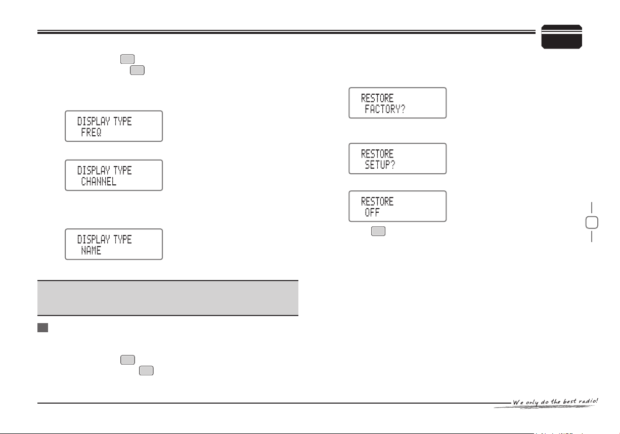
Display Mode Setup
There are 3 display modes for selection: channel frequency + channel
number, channel number, channel name + channel number.
Page 31
27
Press and hold key for over 2 seconds to enter function menu.1.
Repeatedly press key or Microphone [2. UP/DOWN] key until
FUNC
SCAN
LCD displays "DISPLAY TYPE "
Turn selector knob to select desired setup.3.
FREQ: channel frequency + channel number mode.
CHANNEL: channel number mode.
NAME: channel name + channel number mode, if current channel
no name, it will display channel frequency + channel
number.
Default: FREQ4.
Note:
when display mode in programming software is set to channel
number mode and locked, this function will auto-hide. (Sould be
setup in the PC software)
Resume Factory Default
When the transceiver is malfunctioning for wrong operation or setup,
this function can reset all channels and setups to factory default.
Press and hold key for over 2 seconds to enter function menu.1.
Repeatedly press key or Microphone [2. UP/DOWN]
FUNC
SCAN
BACKGROUND OPERATIONS
8
ke y until L C D displays “RESTORE”
Turn selector knob to select desired setup.3.
FACTORY?: Resume all channels and setups to factory default.
SETUP?: Without change the channel, resume all background
setups to factory default
OFF: No Restore.
ENTER
Press key to conrm the selection.4.
Page 32
28
9
MICROPHONE OPERATIONS
While standby repeatedly press key to select desired setup. The
LCD displays:
HIGH: indicates high TX power
Keyboard
You can o pe rate the transceiv er b y keyboard or input desired
frequency/channel through the QHM-04 Microphone keyboard.
Key Lockout
To avoid misplay, switch it to LOCK position, the microphone lamp
off and all keys invalid except [PTT].
Transmitting DTMF Tone By Microphone
Press and hold the [PTT] key, transmit ti ng the desire d DTMF
signaling by the digital key directly.
Function Setup by Microphone Keyboard
Squelch off
♦
Press key while standby, the squelch is disabled when the green
LCD ashes, press key again to enable squelch.
High/Mid/Low Power Switch
♦
LOCK OFF
MIDDLE: indicates middle TX power
LOW: indicates low TX power
Wide/Narrow Band Setup
♦
While standby, repeatedly press to select a bandwidth.
The LCD displays:
"W/N 25K" is wide bandwidth
"W/N 20K" is middle bandwidth
"W/N 12.5K" is narrow bandwidth
Page 33
29
Display Mode Setup
♦
While standby, press key to switch between channel mode and
frequency mode.
Short call
♦
While standby, press key to transmit selected signaling (DTMF,2Tone, 5-Tone)
Channel operations
♦
While standby, press key to enter channel operations function,
repeatedly press key or Microphone [UP/DOWN] key to select
the function options, Turn selector knob to select the desired setup.
Then press key to conrm selection and exit.
Note:
Invalid in channel number mode.
Transmitting Pre-stored DTMF Encode
♦
While standby, press key to check pre-stored DTMF codes, then
press [UP/DOWN] key to select a group. Now you can press [PTT]
key to transmit current DTMF signaling.
Edit And Pre-store DTMF Encode
♦
While standby, press key to check pre-stored DTMF codes, then
press [UP/DOWN] key to select a group for edited and pre-stored.
Press key to enter DTMF editing mode.
You can input the desired DTMF data though the number keys,
then press [PTT] key to transmit and store the DTMF data.
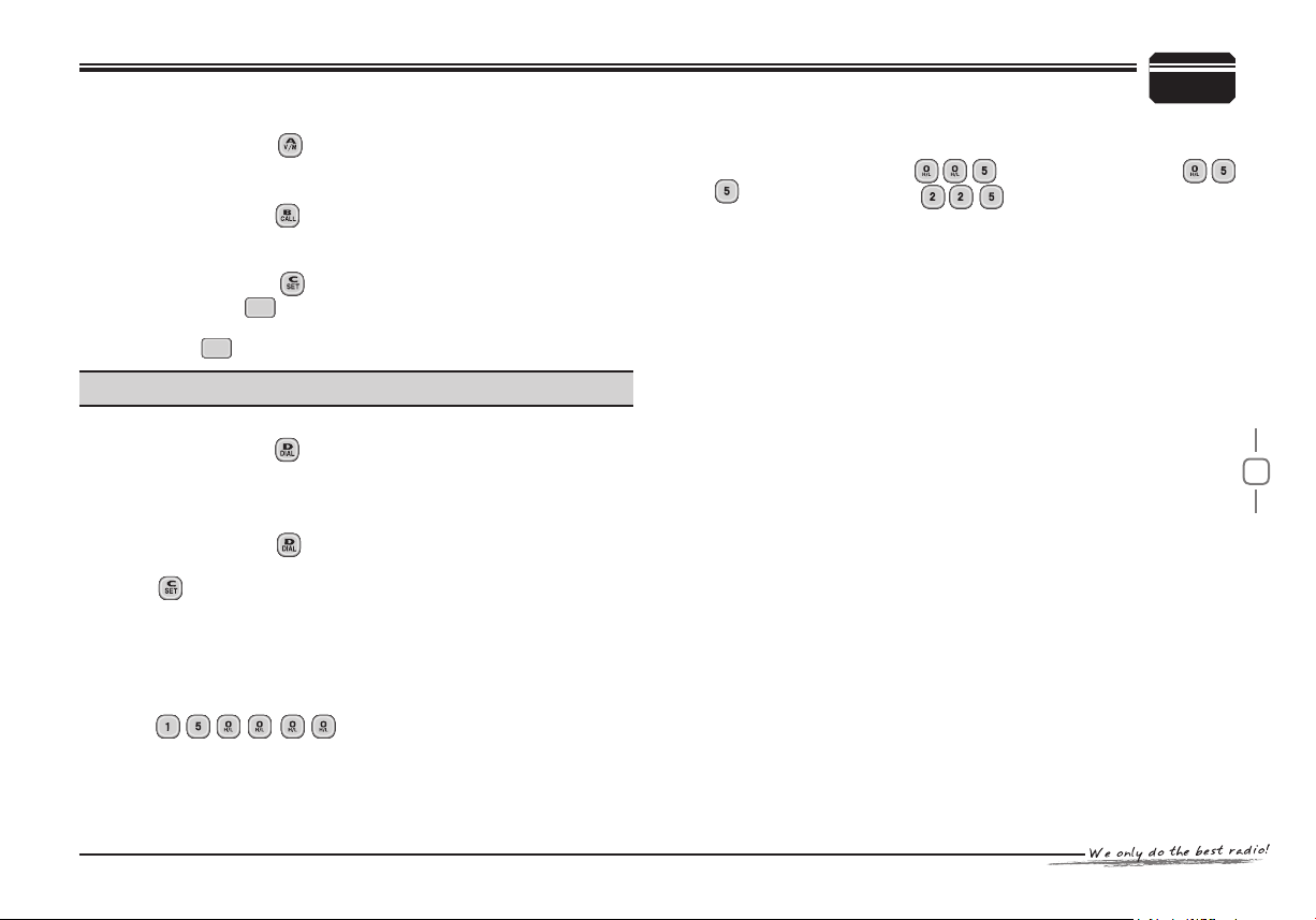
Input Frequency Via Microphone Keyboard
♦
You can input the desired frequency directly via the number keys
While in frequency mode(VFO), e.g, when 150Mhz desired, just
press six nu mbers t o switc h fre qu ency to
150MHz.
Input channel via Microphone keyboard
♦
Wh ile in fr equ ency +ch ann el n umb er m ode or chann el n ame
+channel number mode, input three numbers (001 -250) to switch to
SCAN
SQ/C
MICROPHONE OPERATIONS
a desired channel. If an unedited channel being selected, the transceiver
will emit a beep sound for error, the transceiver will resume to
current channel. e.g, input is for channel number 5,
for channel number 55, for channel number 225.
9
Page 34
30
10
AUXILIARY FUNCTIONS
Initial Setup
Synchronously press and hold key and key to power on the
FUNC
transceiver, then you can start initialization.
(Note: All programming data will be automatically delete after this
operation)
SQ/C
Cable Cloning
With this function, you can copy the programming data of the
transceiver to another one; it can copy parameters and memory
programming data to another transceiver.
Synchronously press and hold the key and key to power on 1.
FUNC
SCAN
main unit and enter clone mode. the LCD displays “CLONE”.
Use CP51 wire cloning cable (optional accessory) to connect main 2.
transceiver with sub-transceiver through PC or MIC interface.
Press main unit key to begin clone, both units will display 3.
ENTER
“CLONE XX”. XX stands for the size of current cloned data.
when the clone nish, the sub-transceiver will restart automatically 4.
and the main unit display “CLONE”, replace the sub-unit with another
unit, and repeat step 2 and step3 to start new clone.(Note: while
main unit in clone mode, repeat step 2 to step 4 to apply cloning
for more units)
Restart the main unit power to exit the clone mode.5.
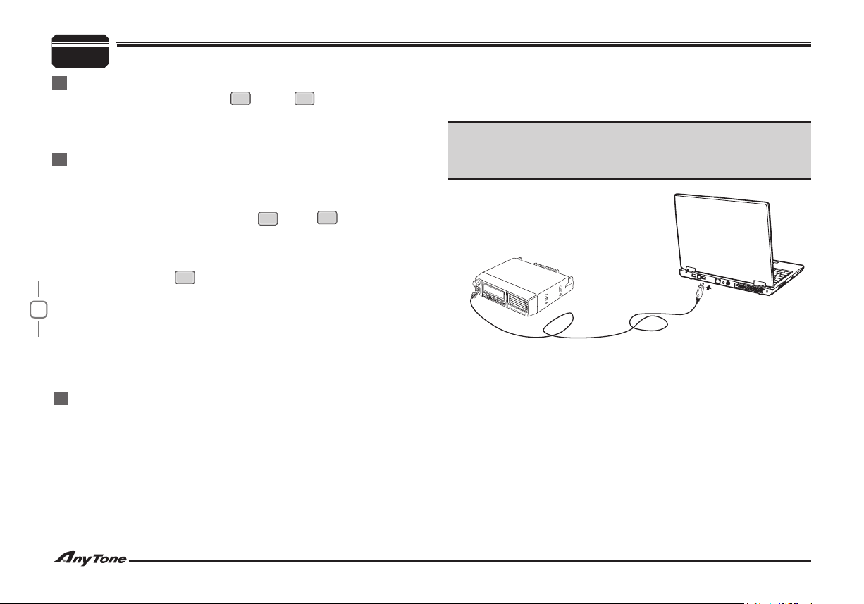
Pr o gramm ing So f tware Insta l ling and Startin g (in
windows XP system)
Double click QPS589 setup.exe, then follow the installing instruction.1.
Click start menu in computer ,under “2. ALL PROGRAMS” menu,
choose and click “USB To Com port” in QPS589 program, install
“USB To Com port” drives by indication.
Connect the optional PC51 USB Programming cable to USB port in 3.
PC with transceiver.
Double click QSP589 shortcut or click QPS589 in procedure index of 4.
start menu, choose serial com port as indicated then click OK to
start programming software.(You shall install software before connecting
the USB cable line.)
Note:
this software has product identify system. So when rstly installing the
software, you have to connect the products, otherwise, you can not
start the software.
Page 35
31
General information Service note
This product has been factory aligned and tested to specication
bef or e shipment. I n normal circum stances, the transceive r will
operate in accordance with these instructions. All adjustable trimmers, coils, and resistors in the transceiver were preset at the
factory. They should only be readjusted by a qualified technician
who is familiar with this transceiver and has the necessary test
equipment. Attempting service or alignment without factory authorization can void the transceiver warranty.
When operated properly, the transceiver will provide years of
service and enjoyment without requiring further realignment.The
information in this section gives some general service procedures
requiring little or no test equipment.
Service
If it is ever necessary to return this equipment to your dealer
or service center for repair, pack it in its original box and packing
material. Include a full description of the problems experienced.
Include your telephone number, fax number, and e-mail address (if
available) along with your name and address in case the service
technician needs to call you for further information While investigating your problem. Do not return accessory items unless you feel
they are directly related to the service problem.
You may return this product for service to the authorized
dealer from whom you purchased it, or any authorized
service center. A copy of the service report will be returned with the
transceiver. Please do not send subassemblies or printed circuit
boards; send the complete transceiver. Tag all returned items with
your name and call sign for identication.
Please mention the model and serial number of the transceiver in
any communication regarding the problem.
If you desire to correspond on a technical or operational problem,
please make your note short, complete, and to the point. Help us
help you by providing the following:
Model and serial number of equipment.•
Question or problem you are having.•
Other equipment in your station pertaining to the problem.•
Meter readings.•
Other related information (menu setup, mode, frequency, key •
sequence to induce malfunction, etc.)
Warning:
Do not pack the equipment in crushed newspapers for shipment.
Extensive damage may result during rough handling or shipping.
Cleaning
The keys, controls, and case of the transceiver are likely to become
soiled after extended use. Remove the controls from the transceiver
and clean them with a neutral detergent and warm water. Use a
neutral detergent (no strong chemicals) and a damp cloth to clean
the case.
MAINTENANCE
11
Page 36
32
13
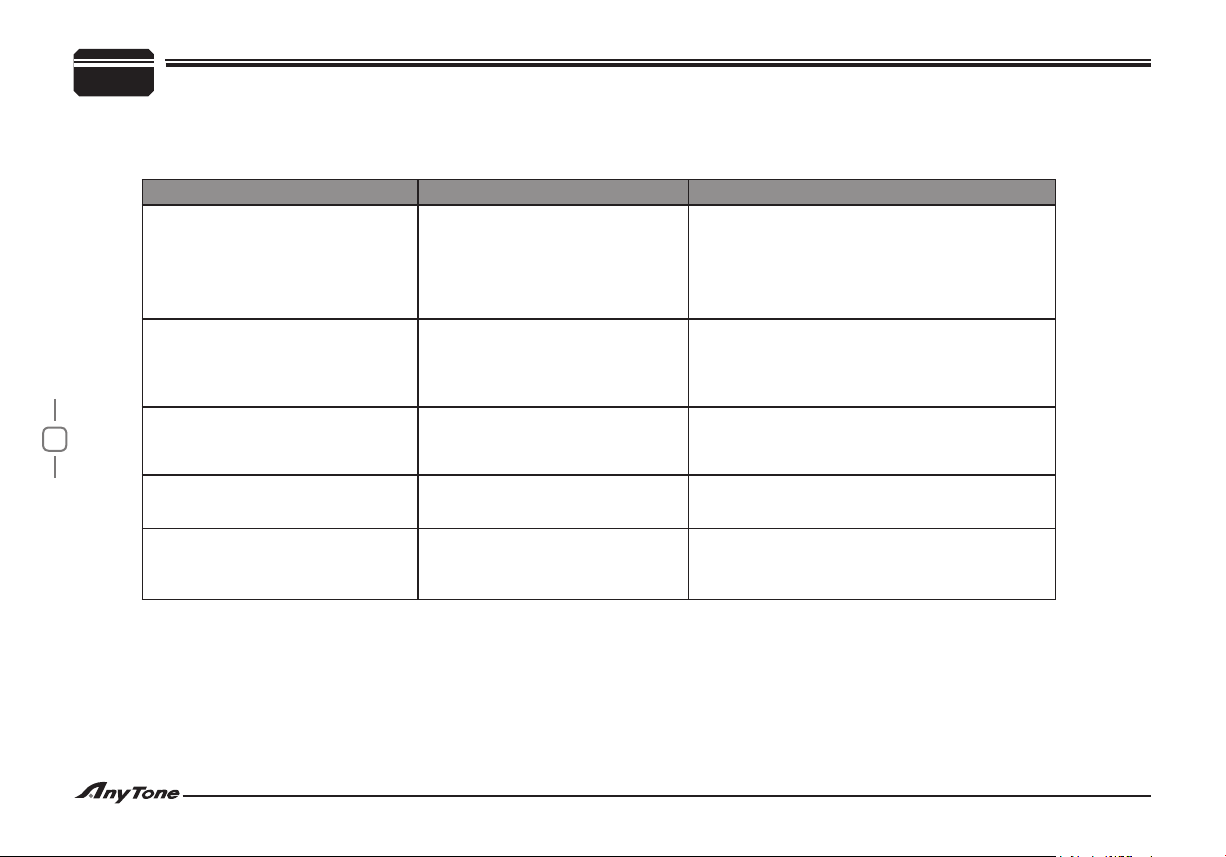
The problems described in the following tables are commonly encountered operational malfunctions. These types of difculties are usually caused
by improper hook-up, accidental incorrect control setup, or operator error due to incomplete programming. These problems are usually not caused by
circuit failure. Please review these tables and the appropriate section(s) of this instruction manual before assuming your transceiver is defective.
TROUBLE SHOOTING
Problem Probable Cause Corrective Action
1.Connect the supplied DC power cable correctly:
Red ( + ); Black ( - ).
2.Look for the cause of the blown fuse(s).
After inspecting and correcting any problems,
install a new fuse(s) with the same ratings.
The supply voltage requirement is 13.8 V DC
15% (11.7 V to 15.8 V DC). If the input voltage is
outside this range, adjust your regulated power
supply and/or check all power cable connections.
Switch OFF the power, then insert themicrophone
plug until the locking tab clicks in place.
1.Check antenna connector
2.Change output power to a high level.
The t ransceiver will not power up
after connecting a 13.8 V DC power
supply an d pr e s s i n g th e po w e r
sw i t c h . Not h i n g appe a r s on th e
display.
The display is too dim,even though
you selected a high brightness level.
You cannot transmit even
though you press Microhpone [PTT].
Scan not available
Communicational range drop down
1.The power cable was connected
backwards.
2.One or more of the power cable
fuses are open.
The supply voltage is too low.
The microphone plug was not
inserted completely into the front
panel connector.
Channel not included in scan when
PC programming
1. Antenna connection problem
2. The transceiver may work in low
power mode
Page 37
33
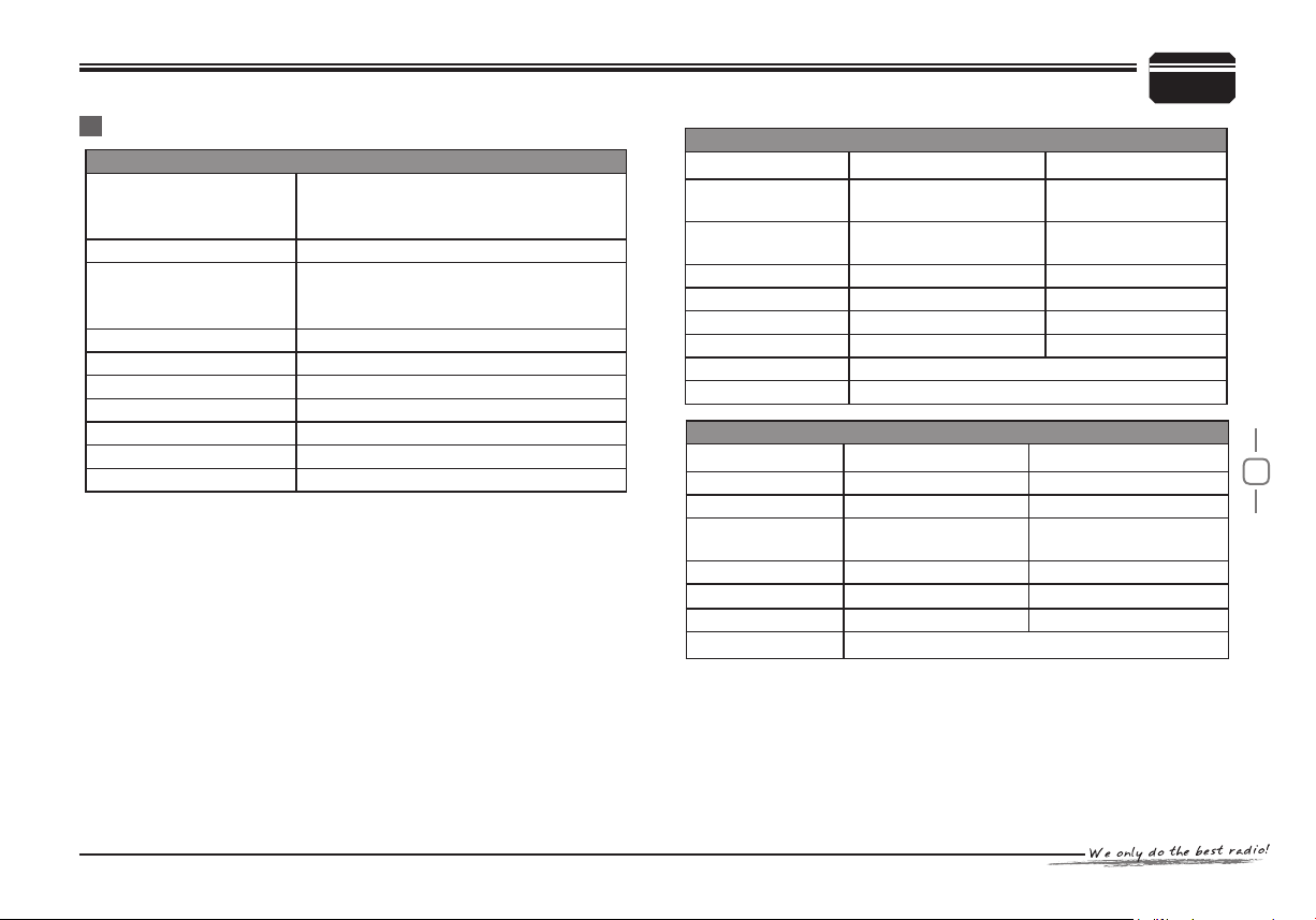
Specifications
General
HF: 33-49MHz 66-88MHz
Frequency Range
Number of Channels
Channel Spacing
Phase-locked Step
Operating Voltage 13.8V DC ±15%
Squelch
Frequency Stability ±2.5ppm
Operating Temperature
Dimensions(WxHxD) 160x155x40mm
Weight 1KG
Specications are subject to change without notice due to advancements
in technology.
VHF: 136-174MHz 245-246MHz
UHF: 400~490MHz
250 channels
25KHz (Wide Band)
20KHz (Middle Band)
12.5K (Narrow band)
5KHz、 6.25KHz
Carrier/CTCSS/DCS/5-Tone/2-Tone/DTMF
-20~+60℃(-4 F~+140F
)
SPECIFICATIONS
Receiver (ETSI EN 300 086 standard testing )
Wide band Narrow band
Sensitivity
(12dB Sinad)
Adjacent Channel
Selectivity
Intermodulation ≥65dB ≥60dB
Spurious Rejection ≥70dB ≥70dB
Audio Response +1~-3dB(0.3~3KHz)
Hum & Noise ≥45dB ≥40dB
Audio distortion ≤5%
Audio power output
Transmitter (ETSI EN 300 086 standard testing )
Power Output 60W /25W/10W(VHF) 45W /25W/10W(UHF)
Modulation 16KΦF3E 11KΦF3E
Adjacent Channel
Power
Hum & Noise ≥40dB ≥36dB
Spurious Emission ≥60dB ≥60dB
Audio Response +1~-3dB(0.3~3KHz) +1~-3dB(0.3~2.55KHz)
Audio Distortion ≤5%
≤0.2μV ≤0.25μV
≥70dB ≥60dB
+1~-3dB(0.3~2.55KHz)
>
2W@10%
Wide band Narrow band
≥70dB ≥60dB
14
Page 38

 Loading...