

Page 1

Page 2

Page 3
THANK YOU!
Thank you very much for choosing our transceiver. transceiver provides you
with reliable, clear and efcient communication service.
The transceiver introduces innovative DSP (Digital Signal Processing) baseband processing system
to achieve high-delity voice processing and encryption. It boasts novelty, best stability, great reliability,
nice timbre and long distance communication as well as fashionable design and smooth exterior lines.
AT-289 is a cost-effective and multi-functional professional transceiver which meets needs of every walk
of life. It is convinced that you will be satised with this transceiver’s quality and functions. For your full
comprehension of the various excellent functions and maintenance, please read the user manual before
use.
NOTE:
When programming the transceiver, read the factory initial data first, then rewrite the frequency and
signaling etc., otherwise errors may occur because of different frequency band etc.
User Manual Applied to: AT-289 UHF FM Transceiver
VHF FM Transceiver
Programming Software: QPS289
Page 4

SAFETY INFORMATION FOR USER
precautions to perform your obligation, prevent personal injury and ensure the safety of transceiver
usage.
ATTENTION:
All tips above apply to accessories of your transceiver. If any device can not work normally,
please contact local
If you use any accessories made by other companies,
operability and safety of the transceiver.
transceiver is excellently designed with advanced technology. Please observe the following
Keep the transceiver and accessories away from children.1.
Please do not try to open or modify the transceiver without permission, non-professionals process 2.
may also cause damage.
Please use assorted battery and charger to avoid damage.3.
Please use assorted antenna to ensure the communication distance.4.
Please do not expose the transceiver to long period of direct sunlight, nor place it close to heat 5.
appliances.
Please do not put the transceiver in excessively dusty or humid areas.6.
Do not use harsh chemicals, cleaning solvents to clean the transceiver.7.
Do not transmit without antenna.8.
When using this transceiver, we recommend transmitting for 1 minute then receiving for 4 minutes. 9.
Continuous transmitting for long time or working in high power will heat the back of the transceiver.
Do not place the transceiver’s hot back close to any surface of plastic.
If any abnormal odor or smoke detected coming from the transceiver, turn off the power and take 10.
off the battery pack and its case. Then contact local
dealers.
dealers.
Company does not guarantee the
Page 5

CONTENTS
UNPACKING ....................................................................................................................... 1
Supplied Accessories .........................................................................................................................1
STANDARD ACCESSORIES/OPTIONAL ACCESSORIES ............................................... 2
Standard Accessories .........................................................................................................................2
Optional Accessories .......................................................................................................................... 2
BATTERY INFORMATION .................................................................................................. 3
Charging Operation .............................................................................................................................3
Charger Applied ..................................................................................................................................3
Notice for Charging Battery .................................................................................................................3
How to Charge ....................................................................................................................................4
Normal Charging Tips .........................................................................................................................6
How to Store the Battery ..................................................................................................................... 6
PREPARATION ................................................................................................................... 8
Installing / Removing the Battery ........................................................................................................ 8
Installing / Removing the Antenna ...................................................................................................... 8
Installing / Removing the Belt Clip ...................................................................................................... 9
Installing the Additional Speaker/ Microphone (Optional) ..................................................................9
Installing/ Removing the Hand Strap (Optional) ..................................................................................10
Professional
FM Transceiver
I
Page 6

CONTENTS
GETTING ACQUAINTED .................................................................................................... 11
Indicator Status and Beep ..................................................................................................................13
[PF1] & [PF2] Key Default ................................................................................................................... 13
BASIC OPERATIONS ......................................................................................................... 14
Switch on / off Transceiver ..................................................................................................................14
Adjusting Volume ................................................................................................................................14
Channel Selection ............................................................................................................................... 14
Group Selection .................................................................................................................................. 15
Receiving ............................................................................................................................................ 15
Transmitting ........................................................................................................................................ 15
Emergency Alarm Function .................................................................................................................16
ADVANCED OPERATIONS ................................................................................................ 17
Call 1/Call 2 .........................................................................................................................................17
Monitor ................................................................................................................................................17
Momentary Monitor .............................................................................................................................17
Temporary Deletion of the Interfering Channel .................................................................................. 18
Squelch Levels Enquiry ......................................................................................................................18
Squelch Levels Setup ......................................................................................................................... 18
Scan .................................................................................................................................................... 19
Professional
II
FM Transceiver
Page 7

CONTENTS
Scramble Setup (Encryption) ..............................................................................................................19
Squelch off ..........................................................................................................................................19
Temporary Squelch off .......................................................................................................................20
Talk Around .........................................................................................................................................20
Frequency Reverse .............................................................................................................................21
Current Channel Power Enquiry ......................................................................................................... 21
TX Power Switch .................................................................................................................................21
Whisper ............................................................................................................................................... 21
Voice Compander (Reduce Noise & Enhance Audio Clarity) ..............................................................22
Battery Capacity Enquiry ....................................................................................................................22
Current Channel Enquiry ....................................................................................................................22
Channel Selector Knob Lockout ........................................................................................................22
BACKGROUND OPERATIONS .......................................................................................... 23
CTCSS / DCS Encode / Decode .........................................................................................................23
Optional Signaling .............................................................................................................................. 23
Wide / Narrow Band Setup .................................................................................................................24
Busy Channel Lockout ........................................................................................................................24
Signaling Relations Setup ................................................................................................................... 25
Channel Scan Skip .............................................................................................................................25
Professional
FM Transceiver
III
Page 8

CONTENTS
TX OFF ............................................................................................................................................... 25
Battery Save Setup .............................................................................................................................25
Time-out Timer ....................................................................................................................................26
Time-Out Timer Pre-Alarm ..................................................................................................................26
TOT Re-transmitting Time Setup ........................................................................................................26
VOX Function ......................................................................................................................................26
Priority Scan Setup ............................................................................................................................. 27
Resume Factory Default ..................................................................................................................... 27
Programming Software Installing & Starting (TAKES WINDOWS XP AS AN EXAMPLE) .. 29
TECHNICAL SPECIFICATIONS ......................................................................................... 30
TROUBLE SHOOTING GUIDE ........................................................................................... 31
ATTACHED CHARTS ......................................................................................................... 32
CTCSS Frequency Chart ....................................................................................................................33
DCS Chart ...........................................................................................................................................34
Professional
IV
FM Transceiver
Page 9

UNPACKING
Carefully unpack the transceiver. We recommend you to identify the items listed in the following
table before discarding the packing material. If any items are missing or have been damaged during
shipment, please contact dealers immediately.
Supplied Accessories
Item Number Quantity
Antenna
Li-ion Battery Pack QB-26L 1
Battery Charger QBC-26L 1
AC adaptor QPS-01 1
Belt Clip BC01 1
Instruction Manual 1
QA01V(136-174MHz)
QA01U(400-480MHz) etc
1
Professional
FM Transceiver
1
Page 10

STANDARD ACCESSORIES/OPTIONAL ACCESSORIES
Standard Accessories
1
Antenna*
QA01V (136-174MHz)
QA01U (400-480MHz) etc.
* Note:
*
For frequency band of antenna, please refer to label indicated in the bottom of the antenna.
Car Charger and QBC-26L Charger should be used together.
Note:
Optional Accessories
Li-ion Battery Pack
QB-26L
Charger
QBC-26L
AC Adaptor
(12V/500mA) QPS-01
Belt Clip
BC01
Instruction
Manual
USB Programming
Cable PC03
Battery Pack for Car
charger CPS01
Professional
2
FM Transceiver
Programming Software
QPS289
Car Charger CPL01*
Earphone
HS03
2
Handheld Microphone
QHM22
Hand Strap
GS01
Page 11

BATTERY INFORMATION
Charging Operation
The battery pack is not charged at the factory; please charge it before use.
Charging the battery pack for the rst time after purchase or extended storage (more than 2 moths)
may not bring the battery pack to its normal operating capacity. After fully charging/ discharging cycle
for two or three times, the operating capacity will reach its best performance. The battery pack life
is over when its operating time decreases even though it is fully and correctly charged. Replace the
battery pack.
Charger Applied
Please use the specic charger appointed by our company. Other models may cause explosion
and personal injury. After installing the battery pack, if the radio displays low battery with red ashing
lamp or voice prompt, please charge the battery.
NOTES
Do not short the battery terminals or ▼ throw the battery into re. Never attempt to remove the
casing from the battery pack, we show no responsibility on any results caused by modifying
freely without permission of our factory.
The ambient temperature should be between 5 ▼
Charging outside this range may not fully charge the battery.
Always switch OFF the transceiver equipped with a battery pack before charging. Otherwise, it ▼
will interfere with correct charging.
To avoid interfering the charging, please do not cut off the power or take out the battery during ▼
charging.
℃
and 40℃while charging is in progress.
Professional
FM Transceiver
3
Page 12

BATTERY INFORMATION
Do not recharge the battery pack if it is already fully charged. This may shorten the life of the ▼
battery pack or damage the battery pack.
Do not charge the battery or transceiver if it is damp. Dry it before charging to avoid danger. ▼
WARNING:
When keys, ornamental chain or other electric metals contact with the battery terminal, the battery
may cause damage or hurt bodies. If the battery terminal short circuit it will generate a lot of heat.
Take care when carrying and using the battery. Remember to put the battery or radio into insulated
container.Do not put it into metal container.
How to Charge
Plug the AC adaptor into the AC outlet, and then plug 1.
the cable of the AC adaptor into the DC jack located
on the back of the Charger. The Indicator l ig hts
orange (1s) and then goes out----waits to charge.
Plug the battery or transcei ver into the charger. 2.
Make sure that the battery terminals are in contact
with charging terminals well. The Indicator turns into
twinkling red-----Pre-charging begins.
After pre-charging for about 5 minutes, the 3. indicator
will stop twinkling----charging begins.
It takes approximately 4 hours to fully charge the 4.
battery. When the lamp lights green, the charging is
nished. Remove the battery or the transceiver equipped with battery from socket.
Professional
4
FM Transceiver
Ac Input
Page 13
BATTERY INFORMATION
NOTE: when charging a power-on transceiver equipped with battery, the indicating lamp will not
turn into green to show the fully charged status. Only when the transceiver is switched off, can the
lamp indicate normally. The transceiver consumes energy when it is power-on, and the charger can
not detect the voltage when the battery has been fully charged. So the charger will charge battery in
constant voltage and fail to indicate correctly whether the battery has been charged fully.
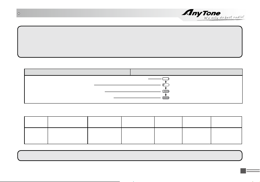
Charging Process5.
Standby (Self-examine lights orange 1second when power on) None
Pre-charging (Pre-charging stage) Red light twinkles for about 5 minutes
Charging (Charge in a constant current) Lights red for about 4 hours
Fully charged (Charge in a constant voltage) Lights green
LED Indicator:6.
STATUS
LED
NOTE: Trouble means battery heating, battery short-circuit or charger short-circuit.
Charging Status Indicator Status
Self-Examine
When Power on
Orange
(for 1 second)
No Battery Pre-charging
None
Red Light
Twinkles
for 5 Minutes
Charge
Normally
Red Green
Fully
Charged
Trouble
Red twinkles
for a long time
Professional
FM Transceiver
5
Page 14
BATTERY INFORMATION
Normal Charging Tips
Self- Examination:1. When charging, orange light twinkles for 1 second and goes out, which means
the charger has passed its self-examination and it can charge the battery normally. If the light
remains orange or the red light twinkles, it means the charger can not pass its self-examination or
charge the battery.
Trickle Pre-Charging:2. If red light twinkles when battery is inserted into the charger, it means the
remnant voltage is low and the charger is trickle-charging the battery (Pre-Charging Status). The
charger will automatically turn into normal charging when the battery reaches a certain electric
quantity, And if the red light stops twinkling, it means the remnant voltage meets a certain electric
quantity, the charger will charge the battery normally.
NOTE:
Trickle charging (Pre-Charging Status) time can not beyond 30 minutes. If the indicating lamp still
twinkles after 30-minute trickle-charging, it means that the charger can not charge the battery. Please
check whether the battery or charger is damaged.
How to Store the Battery
If the battery needs to be stored, keep it in status of 50% discharged.1.
It should be kept in low temperature and dry environment.2.
Keep it away from hot places and direct sunlight. 3.
Professional
6
FM Transceiver
Page 15
BATTERY INFORMATION
WARNING:
Do not short circuit battery terminals. ▼
Never attempt to remove the casing from the battery pack. ▼
Never assemble the battery in dangerous surroundings, spark may cause explosion. ▼
Do not put the battery in hot environment or throw it into re, it may cause explosion. ▼
Professional
FM Transceiver
7
Page 16
PREPARATION
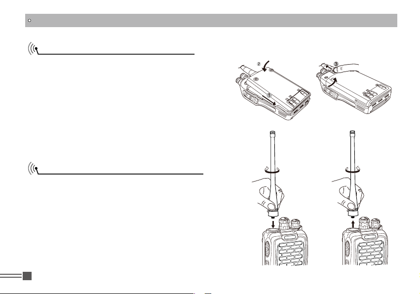
Installing / Removing the Battery
Match the three grooves of the battery pack with 1.
th e c orresponding gu ide s o n t he back of the
transceiver, and then push it.
Press the battery pack until the release latch on 2.
the top of the transceiver locks. After hearing a
“click” sounds, the battery has been locked.
To remove the battery pack, slide up the release 3.
latch an d re m o v e the pa c k aw a y from th e
transceiver.
Installing / Removing the Antenna
■
Installing the Antenna:
Screw the antenna into the connector on the top
of the transceiver by holding the antenna at its base
and turning it clockwise until secure.
Removing the Antenna:
■
Turn the antenna anticlockwise to remove it.
Professional
8
FM Transceiver
Page 17
PREPARATION
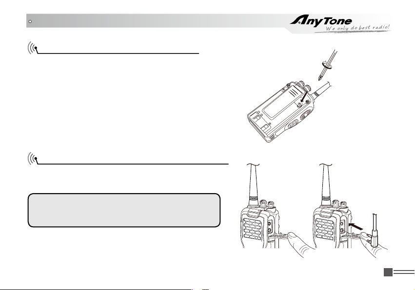
Installing / Removing the Belt Clip
Installing the Belt Clip:
■
Place the belt clip to the corresponding grooves
on the back of the transceiver, and then clockwise
screw it.
Removing the Belt Clip:
■
Anticlockwise turn the screws to remove the belt
clip.
Installing the Additional Speaker/ Microphone (Optional)
Unveil the MIC-SP jack cover and then insert the
Speaker/Microphone plug into MIC-SP jack.
Note:
The transceiver is not completely waterproof while
using the Speaker/Microphone.
Professional
FM Transceiver
9
Page 18
PREPARATION
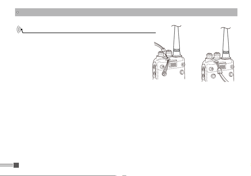
Installing/ Removing the Hand Strap (Optional)
Slide the loop of the hand strap through the eyelet on
the upper rear of the transceiver; then pull the entire
hand strap through the loop to secure the hands strap
in place and lastly tighten the hands strap.
Professional
10
FM Transceiver
Page 19
GETTING ACQUAINTED
4
5
6
1
7
2
10
8
9
3
Professional
11
FM Transceiver
Page 20

GETTING ACQUAINTED
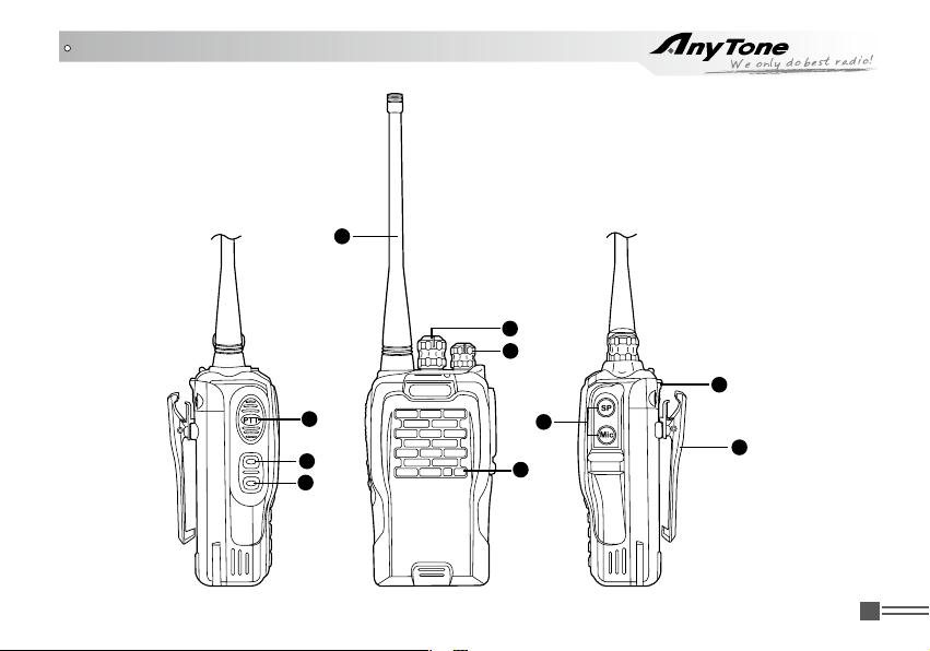
1
Antenna
2
POWER / VOLUME Switch:
Turn clockwise to switch on the transceiver, and turn anticlockwise till hearing “Click” to switch
off the transceiver. After switching on the transceiver, turn clockwise to increase the volume and
anticlockwise to decrease the volume.
3
Emergency Alarm Key
Under the standby conditions, press this key for 1 second to enable alarm function. Press this key
again to exit the alarm status.
4
PTT Key
When you are making a call, please press and hold this key to speak into the microphone. Release
the key to receive.
5
PF1 Key
It can realize different functions by programming.
6
PF2 Key
It can realize different functions by programming.
7
Channel Selector Knob
Turn the selector knob to select desired channel. Turn clockwise to increase channel, anticlockwise to
decrease channel.
8
Additional Microphone / Speaker Jack、Reading / Writing frequency Jack
9
Belt Clip
10
Battery Lock
Professional
12
FM Transceiver
Page 21
GETTING ACQUAINTED
Indicator Status and Beep
Warning on low voltage
Transmitting/Reading
Frequency
Transceiver emits a low voltage beep at intervals of 60 seconds,
and red light twinkles.
Lightens red all the time.
Receiving/Writing Frequency Lightens green all the time
Scan Green light twinkles every second.
DTMF Successfully Decoded Red and green light twinkles at the same time.
Key Operation
Voices "DU" into any function, "DU DU" or beep voice prompt to
exit any function
[PF1] & [PF2] Key Default
Press [PF1] Battery Capacity Enquiry
Press [PF2] Squelch off
Press and hold [PF1] Whisper
Press and hold [PF2] TX Power Switch
Professional
FM Transceiver
13
Page 22
BASIC OPERATIONS
Switch on / off Transceiver
Switch on Transceiver: Under power-off state, turn POWER / VOLUME clockwise till hearing
"Click" to switch on the transceiver. The transceiver will announce "Power on" when power-on.
Switch off Transceiver: Under power-off state,turn POWER / VOLUME anticlockwise till hearing
"Click" to switch off the transceiver.
Adjusting Volume
Under power-on state, turn POWER / VOLUME switch to adjust the volume. Turn clockwise to
increase the volume, and anticlockwise to decrease the volume. You can press the programmed key
of momentary squelch off [PF1] / [PF2] to monitor current volume.
NOTE: You can firstly press the programmed key of momentary squelch off [PF1] / [PF2] to monitor
the background noise and meanwhile turn POWER / VOLUME to adjust the volume. Under the
communicating state, you can adjust volume as per your need more accurately.
Channels Selection
Under the standby conditions, turn channel selector knob to choose the desired channel, and
the transceiver will announce the adjusted channel. Turn clockwise to increase the channel,
anticlockwise to decrease the channel.
NOTE: The transceiver will emit a voice prompt when current channel is blank.
Professional
14
FM Transceiver
Page 23
BASIC OPERATIONS
Group Selection
There are128 channels in total which are divided into 8 groups with 16 channels in each group.
After the rst channel is selected, press and hold [PF2] to switch on the transceiver. Holding [PF2]
for 2 seconds, the transceiver will announce current group number. Under this condition, turn the
selector knob to choose the desired group.
NOTE: You can enable or disable the group selection function by programming software.
Receiving
You can hear the transmitting party's calling when the channel you are operating is called and the
LED light turns green.
NOTE:
You may not receive the calling if you set a high squelch off level of the transceiver.
If current channel has been programmed with signaling, you can only hear the call from a same
signaling, other calls can not be heard.
Transmitting
Before transmitting, make sure that the channel you want to use is not in busy state through
monitoring for a while by pressing the programmed Momentary Squelch off [PF1] / [PF2] key. Under
these conditions, press the [PTT] key and speak into microphone. Please keep around 2.5-5cm
distance between microphone and your lip. And please speak in normal tone to make the receiver
obtain best tone quality.
Professional
FM Transceiver
15
Page 24

BASIC OPERATIONS
Emergency Alarm Function
Press and hold this key for over 1 second to start the Emergency Alarm Function.
Once this function is started, the transceiver will voice alarm beep, start transmitting and send the
alarm beep to companions or systems. Restart the power supply or press Emergency Alarm key
again to exit the emergency alarm function.
Professional
16
FM Transceiver
Page 25
ADVANCED OPERATIONS
The [PF1] and [PF2] keys are program mable. Th ey can realize the followi ng functions by
programming software.
NOTE: When programming the following functions as [PF1] 1S key or [PF2] 1S key, you need to press
the [PF1] / [PF2] key for one second till the transceiver beeps and then release the key to realize the
programmed function.
Call 1/Call 2
Under the standby conditions, press the programmed key of Call1/Call2 ( [PF1]/[PF2] ) to transmit
the prestored and selected DTMF signaling.
Monitor
Under the standby conditions, pressing the programmed key of monitor [PF1] / [PF2], the
transceiver emits "DU" beep and then comes into the monitor state. Under these conditions,
transceiver will ignore CTCSS / DCS decode and monitor signal of the other party as long as
receiving the matched carrier wave. Press this key again, transceiver emits "DU DU" beep and exits
the monitor state.
Momentary Monitor
Under the standby conditions, press and hold the programmed key of momentary monitor [PF1]/
Professional
FM Transceiver
17
Page 26
ADVANCED OPERATIONS
[PF2], the transceiver emits "DU" beep and then comes into monitor state. Under these conditions,
transceiver will ignore CTCSS/DCS decode and monitor signal of other party as long as receiving
the matched carrier wave. Release this key, transceiver emits "DU DU" beep and exits the monitor
state.
Temporary Deletion of the Interfering Channel
This function can temporarily delete the interfering channel or occupied channel from scan list.
When scan stops on one channel, pressing the programmed key of Temporary Deletion of the
Interfering Channel, transceiver emits "DU" beep and temporarily deletes this channel from scan list.
But the priority channels cannot be temporarily deleted. If only one or two channels are in scan list,
this operation is not available. Restart the transceiver to add the temporarily deleted channels into
scan list again.
Squelch Levels Enquiry
Under the standby conditions, pressing the programmed Squelch Levels Enquiry key, transceiver
will announce current squelch level.
Squelch Levels Setup
This function is used to setup the receiving signal intensity. If the receiving signal intensity reaches
a certain level, you can hear the other party calling, otherwise transceiver will remain mute.
Professional
18
FM Transceiver
Page 27
ADVANCED OPERATIONS
Under the standby conditions, pressing the programmed Squelch Levels Setup, transceiver will
voice the adjusted squelch level.
Scan
Scan function can be used in monitoring every channel of current group.
Under the standby conditions, pressing the programmed scan key, transceiver emits "DU" beep
and comes into scan state. It scans channels in scan list one by one. When one channel receives
a matching signal, the transceiver will temporarily stay in this channel till the signal disappears.
Pressing the scan key again, transceiver emits "DU DU" beep, exits scan and switches the working
channel to returned channel which is programmed by users in advance (Please refer to returned
channel in the programming software.).
Scramble Setup (Encryption)
This special audio process can offer a more condential communication. It makes transceivers of
same frequency receive disordered noises only.
Under the standby conditions, pressing the programmed Scramble key, transceiver emits "DU"
beep and enables Scramble function. Repeat the same operation, transceiver emits "DU DU" beep
and disables the Scramble function.
Squelch off
Under the sandby conditions, pressing the programmed key of Squelch off [PF1] / [PF2], the
Professional
FM Transceiver
19
Page 28
ADVANCED OPERATIONS
squelch circuit is not mute and at present you can hear the background noise. Press this key again,
transceiver emits "DU DU" beep, and the squelch circuit becomes mute. By using this function you
can monitor the weaker signal which is hard to receive.
Temporary Squelch off
Under standby conditions, press and hold programmed key of Temporary Squelch off [PF1]/[PF2],
transceiver emits "DU" beep and the squelch circuit is not mute and at present you can hear the
background noise. Release this key, then the transceiver emits “DU DU” and the squelch circuit is
mute. By using this function you can monitor weak signal which is hard to receive.
Talk Around
Under the standby conditions, pressing the programmed key of Talk Around, transceiver emits "DU"
beep and then the current channel comes into Talk Around state. Under these conditions, transceiver
will transmit by receiving frequency. Also, the setting code (CTCSS / DCS) will interchange encoding
signal as decoding signal.
Press this key again, transceiver emits "DU DU" beep and exits the Talk Around state.
Note:Under the talk around state, the transceiver can not communicate with other transceivers through
repeaters.
Professional
20
FM Transceiver
Page 29
ADVANCED OPERATIONS
Frequency Reverse
Under the standby conditions, pressing the programmed key of Frequency Reverse, transceiver
emits "DU" beep and then comes into Frequency Reverse state. After that, the current channel RX
frequency will be switched to TX frequency, and the CTCSS or DCS signal which has been setup will
be also switched. Pressing this key again, the transceiver exits reverse function with "DU DU" beep.
Current Channel Power Enquiry
Under the standby conditions, pressing the programmed key of "Curre nt Channe l Power
Enquiry", transceiver announces the current channel power state.
TX Power Switch
Under the standby conditions, pressing the programmed key of "TX Power Switch", transceiver
emits BEEP prompt and announces the switched power.
Whisper
When this function is enabled, other party can hear a higher voice as long as you speak in a lower
voice.
Under the standby conditions, pressing the programmed key of "Whisper", transceiver emits "DU"
beep and enables Whisper function. Pressing the same key again, the transceiver exits Whisper
function with "DU DU" beep.
Professional
FM Transceiver
21
Page 30
ADVANCED OPERATIONS
Voice Compander (Reduce Noise & Enhance Audio Clarity)
Enable this function to reduce background noise and improve audio clarity, which is especially
helpful for long-distance communication.
Under the standby conditions, pressing the programmed key of "Voice Compander", transceiver
enables the Voice Compander function with "DU" beep. Pressing the key again, transceiver exits
Voice Compander function with "DU DU" beep.
Battery Capacity Enquiry
Under the standby conditions, pressing the programmed key of "Battery Capacity Enquiry",
transceiver announces current battery capacity.
Current Channel Enquiry
Under the standby conditions, pressing the programmed key of "Current Channel Enquiry",
transceiver announces current channel number.
Channel Selector Knob Lockout
Enable this function to prevent normal communication failure caused by channel misadjustment.
Under the standby conditions, pressing the programmed key of "Channel Selector Knob
Lockout", transceiver enables the Channel Selector Knob Lockout function with "DU" beep. Press
the key again, transceiver exits the Channel Selector Knob Knockout function with "DU DU" beep.
Professional
22
FM Transceiver
Page 31
BACKGROUND OPERATIONS
CTCSS / DCS Encode / Decode
Users can set independent CTCSS / DCS encode / decode for every channel by programming
software.
Optional Signaling
Users can enable or disable the Optional Signaling in every channel by programming software.
This Signaling function is similar to CTCSS/DCS which embodies functions as Selective Call, Group
Call, All Call, PTT ID, and Remotely stun and Waken.
1. PTT ID: If current channel is edited with PTT ID, the transceiver will send transmitting ID when
pressing or releasing PTT key.
You can set group call wildcard for each group2. by programming software . (DTMF character A.
B.C.D.*** or “#”).
The caller can call different groups by sending different group call codes. When the receiving
party receives a valid ID code, one or all of the characters would be replaced by wildcard characters
and the receiving part can realize all call, group call or selective call. It is much easy and exible to
realize all call, group call and etc by using group call code.
For example:
Group code :"C"
Radio A Radio B Radio C Radio D
ID code of the receiving party is 123
If the calling party uses "C23" to call, Radio A and Radio B will receive the call.
If the calling party uses"CC5" to call, Radio C and Radio D will receive the call.
If the calling party uses "CCC" to call, All Radios would receive the call..
223
235
355.
Professional
FM Transceiver
23
Page 32
BACKGROUND OPERATIONS
3.This transceiver is set with 16 groups of DTMF code, users can program and use them exibly.
Wide / Narrow Band Setup
On the basis of national conditions, users can set channel spacing as 25K (wide band), 20K (
middle band) or12.5K (narrow band) to communicate on the transceiver by programming software.
This transceiver can realize 25K (wide band), 20K (medium band) or 12.5K (narrow band) as
communication way.
Busy Channel Lockout
When BCL function is enabled, you can not transmit in busy channel. BCL prevents you from
interfering with other parties who is using the same frequency point that you select. Under this
condition, if you press the [PTT] to transmit, the transceiver will emit beep prompt and return to
receiving mode.
Users can set Busy Channel Lockout mode by programming software.
Repeater (BTL):1. Repeat lockout, transmitting is inhibited when current channel receives a
matched carrier with different CTCSS/DCS.
Carrier wave (BCL):2. Carrier busy lockout, transmitting is inhibited when current channel receives
a matched carrier wave.
3. Close: BCL disabled, you can do transmission under whatever receiving state.
Professional
24
FM Transceiver
Page 33
BACKGROUND OPERATIONS
Signaling Relations Setup
Users can set relations between CTCSS/DCS signal and DTMF signal by programming software.
AND: Only when a matching CTCSS/DCS signal and a DTMF signal are received, can calling of
other party be heard.
OR: As long as a matching CTCSS/DCS signal or a DTMF signal is received, calling of the other
party can be heard.
Channel Scan Skip
Users can choose whether to set current channel as Scan Skip by programming software.
Transceiver will skip current channel during scan when it is set as Scan Skip.
TX OFF
Users can enable or disable the Transmitting Inhibited Function in current channel by programming
software. Once this function is enabled, [PTT] key becomes invalid key, and the transceiver only
works in receiving mode.
Battery Save Setup
When this function is enabled, the transceiver can efficiently reduce battery consumption. The
transceiver will automatically switch on Battery Save Function when not receiving any signal or
making any operations. But when the transceiver receives a matching signal or make operations, it
Professional
FM Transceiver
25
Page 34
BACKGROUND OPERATIONS
will automatically exit this function.
Time-out Timer
The purpose of the Time-out Timer is to prevent any caller from using a channel for an extended
period of time. If you continuously transmit for a period of time that exceeds the programmed time
set in advance, the transceiver will stop transmitting with voice prompt.
Users can set TOT timer by programming software.
Time-Out Timer Pre-Alarm
The Time-Out Timer Pre-Alarm is to alarm users that overtime transmission is going to happen.
Users can program desired TOT Pre-Alarm time by programming software.
TOT Re-transmitting Time Setup
TOT Re-transmitting Time is the interval betw ee n the stopped overtime transmission and
allowed re-transmission. Pressing PTT key before Re-transmitting time, the transceiver will inhibit
transmission with voice prompt.
Users can set desired TOT Re-transmitting Time by programming software.
VOX Function
When this function is enabled, you can begin transmitting by tted high voice, no needing to press
Professional
26
FM Transceiver
Page 35
BACKGROUND OPERATIONS
the [PTT] key.
Users can enable or disable the VOX function by programming software.
Priority Scan Setup
This transceiver can be set with two priority channels at the same time.Users can set the desired
priority scan by programming software. If transceiver set priority scan, under scanning and receiving
no signal state, it will scan every channel and also test priority channel at a time. When the non-
priority channel receives signal, it will test priority channel according to yback time A and yback
time B setup by users.
Resume Factory Default
Once transceiver works abnormally for wrong operations or wrong programming, users can start
this function to resume all functions and channels as Factory Default.
Press [PTT] and [PF1] key synchronously to switch on transceiver. Holding the two keys for more
than 1 second, the transceiver will resume Factory Default after announcing current channel number.
Professional
FM Transceiver
27
Page 36
PROGRAMMING SOFTWARE LNSTALLING & STARTING (TAKES WINDOWS XP AS AN EXAMPLE)
Double-click “QPS289 SETUP.EXE”, and then install the 1.
software as per computer instructions.
Click "START" menu , selec t and clic k "USB TO C OM 2.
PORT" in the "QPS289" program from "ALL PROGRAM".
Connect the 3. optional cable PC03 to the USB port in PC
device and connect the transceiver with the other end of
cable.
Double click "QPS289" setup short-cut icon or click "START" 4.
menu to choose QPS289 entry in the QPS289 program
from "ALL PROGRAMS" menu (Refer to picture 1).
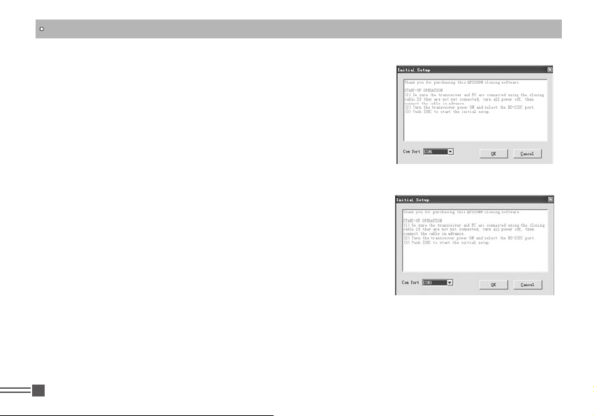
As per computer command, choose serial port "COM Port" 5.
rstly (Refer to picture2), then click OK to start programming
software.
TIPS:
In one individual computer, users need to choose different
COM Port number when USB cable is connected with different
USB port.
To program frequency, power on the transceiver rstly. Do
not power on/off the transceiver when it is connected with
computer. Otherwise, the transceiver can not read or write
frequency well. If this condition happens, please rstly close
the programming software, disconnect USB Connector(PC03)
fr om comp ute r, then, con nect the US B co n nec tor wit h
Professional
28
FM Transceiver
(picture 1)
(picture 2)
Page 37
PROGRAMMING SOFTWARE LNSTALLING & STARTING
(TAKES WINDOWS XP AS AN EXAMPLE)
computer again and select the corresponding COM Port to start the programming software.
So, please power on the transceiver before connecting with the computer. Do not reset the transceiver
when the transceiver is connected with the computer.
NOTE: The programming software of this transceiver has identifying system. Therefore, when you
start programming software at the first time, you should connect the transceiver and then you can run
the software, otherwise the software cannot be run.
Professional
FM Transceiver
29
Page 38
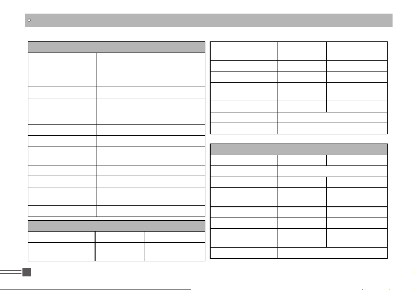
TECHNICAL SPECIFICATIONS
General
VHF:136-174MHz
Frequency Range
VHF:350 -390MHz
UHF:400-480MHz
UHF:450-520MHz
Channel Capacity 128 channels
25KHz (Wide Band)
Channel Spacing
20KHz(Middle Band)
12.5KHz (Narrow Band)
Phase-locked Step 5KHz, 6.25KHz
Operating Voltage 7.4V DC ±20%
Battery Life
More than 14 Hours (1500mAh),
by 5-5-90 work cycle
Frequency Stability ±2.5ppm
Operating Temperature -20℃~ +55
Size
260×60×35mm (with battery pack,
antenna)
℃
Weight 208 g (with battery pack, antenna)
Receiving Part(ETSI EN 300 086 Standard Test)
Wide band Narrow band
Sensitivity(12dB
SINAD)
Professional
30
FM Transceiver
≤0.25μV ≤0.35μV
Adjacent Channel
Selectivity
≥70dB ≥60dB
Intermodulation ≥65dB ≥60dB
Spurious Rejection ≥70dB ≥70dB
Audio Response
+1~-3dB
(0.3~3KHz)
Hum & Noise ≥40dB
+1~-3dB
(0.3~2.55KHz)
36dB
≥
Audio Distortion ≤5%
Audio Power Output 1000mW/10%
Transmitting Part(ETSI EN 300 086 Standard Test)
Wide band Narrow band
Power Output 5W/2W/0.5W
Modulation 16KΦF3E 11KΦF3E
Adjacent Channel
Power
≥70dB ≥65B
Hum & Noise ≥40dB ≥36dB
Spurious Emission ≤-36dB ≤-36dB
Audio Response
+1~-3dB
(0.3~3KHz)
+1~-3dB
(0.3~2.25KHz)
Audio Distortion ≤5%
Page 39
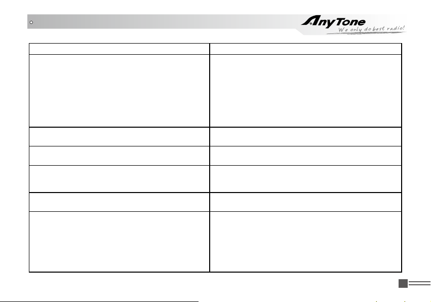
TROUBLE SHOOTING GUIDE
Problem Corrective Action
No Power
Ba tte ry pow er d ies shortl y a fte r c o rre ctl y
charging.
Transceiver cannot scan
All band noisy after programmed or green light
always lightens
No sound after using microphone for a while
Communication distance becomes short, and it
is low sensitivity
The battery pack may be exhausting. Recharge A.
or replace the battery pack.
The battery pack may not be installed correctly. B.
Remove the battery pack and install it again.
The power switch is broken; send it to local C.
dealers to repair.
Battery touch is broken; send it to local dealers D.
to repair.
The battery pack life is finished. Replace the
battery pack with a new one.
The channels are not in scan list. (Professionals
set it.)
Turn on squelch when programmed. Non-
pr ofe s sio n als are ad v ise d no t to adj ust thi s
function.
Earphone jack is broken. (Please contact with
local dealers to repair it.)
Check whether the antenna is in good condition A.
and the antenna base do not come adrift.
Us ers sele ct w rong fre quen cy t ype whic h B.
is not in acc ord wit h this tran sceiver when
programming.
Whether it has set in low power output. (Please C.
contact with local dealers to repair it.)
Professional
FM Transceiver
31
Page 40
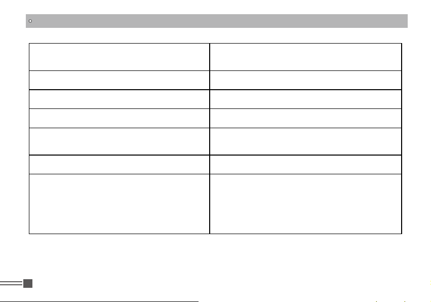
TROUBLE SHOOTING GUIDE
Cannot talk to or hear other members in your
group
Can not power on or frequent power-off
The receiver gets low or intermittent voice from
the caller
Unstable communication with loud background
noise
Loudspeaker become lower or with “ka k a”
sound after using a certain time
Receive voice from the other party but can not
transmit
Receiving Indicator (green light) lightens but no
sound
Professional
32
FM Transceiver
Different frequency or channel, please change it.A.
Different CTCSS / DCS please reset it.B.
Out of communication range.C.
Check whether the battery touch is out of sharp or
broken.
Check weather the MIC is stoppage. (Otherwise,
please contact with local dealers to repair it.)
Out of communication range or obstruct by tall
buildings or in basement and so on.
Check whether the loudspeaker net is broken. Iron
powder or sundries is in the loudspeaker. (Please
contact with local dealers to repair it.)
Ch eck [P TT] key. ( Ple ase conta ct wit h l oca l
dealers to repair it.)
Low volume, please turn on clockwise.A.
Loudspeaker is broken. (Please contact with B.
local dealers to repair it.)
Earphone jack is broken. (Please contact with C.
local dealers to repair it.)
Volume switch is broken. (Please contact with D.
local dealers to repair it.)
Page 41
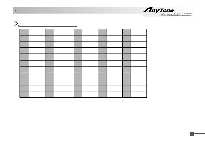
ATTACHED CHART
CTCSS Frequency Chart
1 67.0 12 94.7 23 141.3 34 179.9 45 225.7
2 69.3 13 100.0 24 146.2 35 183.5 46 229.1
3 71.9 14 103.5 25 151.4 36 186.2 47 233.6
4 74.4 15 107.2 26 156.7 37 189.9 48 241.8
5 77.0 16 110.9 27 159.8 38 192.8 49 250.3
6 79.7 17 114.8 28 162.2 39 196.6 50 254.1
7 82.5 18 1183.8 29 162.5 40 199.5
8 85.4 19 123.0 30 167.9 41 203.5
9 88.5 20 127.3 31 171.3 42 206.5
10 91.5 21 131.8 32 173.8 43 210.7
11 94.8 22 136.5 33 177.3 44 218.1
Professional
FM Transceiver
33
Page 42
ATTACHED CHART
DCS Chart
1 017 18 073 35 165 52 261 69 356 86 464 103 632
2 023 19 074 36 172 53 263 70 364 87 465 104 645
3 025 20 114 37 174 54 265 71 365 88 466 105 654
4 026 21 115 38 205 55 266 72 371 89 503 106 662
5 031 22 116 39 212 56 271 73 411 90 506 107 664
6 032 23 122 40 217 57 274 74 412 91 516 108 703
7 036 24 125 41 223 58 305 75 413 92 523 109 712
8 043 25 131 42 225 59 306 76 423 93 526 110 723
9 047 26 132 43 226 60 311 77 425 94 532 111 731
10 050 27 134 44 243 61 315 78 431 95 534 112 732
11 051 28 135 45 244 62 325 79 432 96 546 113 734
12 053 29 143 46 245 63 331 80 445 97 565 114 743
13 054 30 145 47 246 64 332 81 446 98 606 115 754
14 055 31 152 48 251 65 343 82 452 99 612 116 765
15 065 32 155 49 252 66 345 83 454 100 624
16 071 33 156 50 254 67 346 84 455 101 627
17 072 34 162 51 255 68 351 85 462 102 631
NOTE: 1. "N" stands for positive code. "I" stands for inverted code. 232 groups of DCS in total.
2. Overstriking marks are non-standard DCS.
Professional
34
FM Transceiver
Page 43

Page 44

Qixiang Electrcon Science & Technology Co., Ltd.
Adress: Qixiang Building, Tangxi Industrial Zone, Luojiang District,
Quanzhou 362011, Fujian Province, China
Website: http://www.qxdz.cn
A1.0-10/07
 Loading...