

Page 1
horizontal contact toaster
D
L
I
S
T
E
C US
I
N
T
E
R
T
E
K
www.ajantunes.com
HCT-2010
owner’s manual
Manufacturing Numbers:
9210320
9210321
A
T
T
I
I
O
N
N
A
S
C
US
L
I
S
E
T
P/N 1011236 Rev. C 04/16
L
CM
D
D
I
S
E
T
Page 2
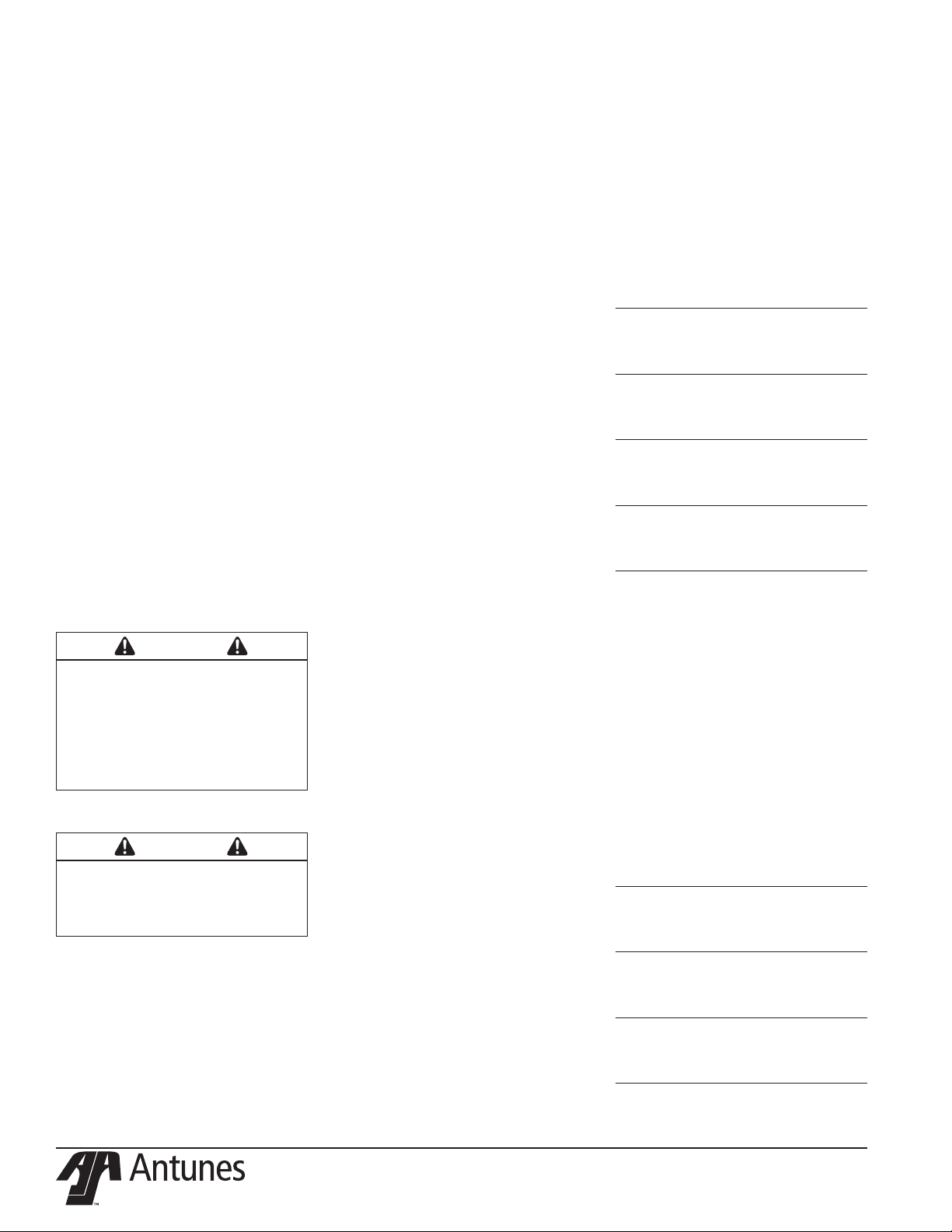
Table of Contents
General .................................................. 2
Warranty Information ............................. 2
Service/Technical Assistance ................... 2
Important Safety Information ................. 3
Warnings ................................................ 3
Specifications ......................................... 4
Installation ............................................. 5
Operating Instructions ............................ 5
Light/Dark Adjustments .......................... 6
User Mode.............................................. 6
Manager Mode ...................................... 6
Safety Features ....................................... 7
Fault Messages .......................................7
Error Codes ............................................ 7
Daily Maintenance ................................. 8
Replacing the Release Sheet
(Every 3-5 Weeks)................................... 9
Replacing the Silicone Belts
(Every 2–4 Months) ................................ 9
About The HTC-2010 Clip Style Belt ....... 9
Checking the Conveyor Belt Chains
(Every 3–6 Months) ................................ 9
Troubleshooting...................................... 11
Replacement Parts ..................................14
Wiring Diagram ...................................... 18
HTC-2010 Clip Style Belt Instructions..... 20
Notes ...................................................... 21
IMPORTANT
A.J. Antunes & Co. reserves the right
to change specifications and product
design without notice. Such revisions do
not entitle the buyer to corresponding
changes, improvements, additions or
replacements for previously purchased
equipment.
IMPORTANT
Keep these instructions for future reference. If the unit changes ownership,
be sure this manual accompanies the
equipment.
GENERAL
This manual provides the safety, installation,
and operating procedures for the Horizontal
Contact Toaster. We recommend that all information contained in this manual be read prior
to installing and operating the unit.
This product is manufactured from the finest
materials available and assembled to Roundup’s
strict quality standards. This unit has been tested
at the factory to ensure dependable trouble-free
operation.
WARRANTY INFORMATION
Please read the full text of the Limited
Warranty in this manual.
If the unit arrives damaged, contact the carrier immediately and file a damage claim with
them. Save all packing materials when filing a
claim. Freight damage claims are the responsibility of the purchaser and are not covered
under warranty.
The warranty does not extend to:
• Damages caused in shipment or damage as result of improper use.
• Installation of electrical service.
• Normal maintenance as outlined in
this manual.
• Malfunction resulting from improper
maintenance.
• Damage caused by abuse or careless
handling.
• Damage from moisture into electrical
components.
• Damage from tampering with, removal
of, or changing any preset control or
safety device.
SERVICE/TECHNICAL
ASSISTANCE
If you experience any problems with the
installation or operation of your unit, contact
your local Roundup Authorized Service Agency.
Fill in the information below and have it
handy when calling your Authorized Service
Agency for assistance. The serial number is on
the specification plate located on the rear of
the unit.
Purchased From
Date of Purchase
Model Number
Serial Number
Manufacturing Number
Use only genuine Roundup replacement parts
in this unit. Use of replacement parts other
than those supplied by the manufacturer will
void the warranty. Your Authorized Service
Agency has been factory trained and has a
complete supply of parts for this unit.
Visit www.ajantunes.com or contact the factory at 1-630-784-1000 to locate your nearest
Authorized Service Agency.
Refer to the service agency directory packaged
with your manual and fill in the information
below.
Authorized Service Agency
Name
Phone Number
Address
2
P/N 1011236 Rev. C 04/16
Page 3

IMPORTANT SAFETY
INFORMATION
Use the following guidelines for safe operation of the unit.
• Read all instructions before using
equipment.
• For your safety, the equipment is furnished with a properly grounded cord
connector. Do not attempt to defeat
the grounded connector.
• Install or locate the equipment only
for its intended use as described in
this manual. Do not use corrosive
chemicals in this equipment.
• Do not operate this equipment if it
has a damaged cord or plug, if it is
not working properly, or if it has been
damaged or dropped.
• This equipment should be serviced by
qualified personnel only. Contact your
nearest Authorized Service Agency for
adjustment or repair.
• Do not block or cover any openings on
the unit.
• Do not immerse cord or plug in water.
• Keep cord away from heated surfaces.
• Do not allow cord to hang over edge
of table or counter.
• Turn the power off, unplug the power
cord, and allow unit to cool down
before performing any service or
maintenance on the unit.
• The procedures in this manual may
include the use of chemical products.
These chemical products will be
highlighted with bold face letters followed by the abbreviated HCS (Hazard
Communication Standard). See Hazard
Communication Standard manual for
the appropriated Material Safety Data
Sheets (MSDS).
• The toaster should be grounded
according to local electrical codes to
prevent the possibility of electrical
shock. It requires a grounded receptacle with separate electrical lines,
protected by fuses or circuit breaker of
the proper rating.
• All electrical connections must be in
accordance with local electrical codes
and any other applicable codes.
• Do not clean this appliance with a
water jet.
• Bread may burn. Therefore toasters
must no be used near or below curtains or other combustible walls and
materials. Failure to maintain safe
operating distances may cause discoloration or combustion.
• Make sure both ends of the Silicone
Belt are aligned evenly before installing the Silicone Belt Pin.
• Failure to use the Release Sheet may
result in damage to the equipment
and loss of warranty coverage.
WARNINGS
Be advised of the following warnings when
operating and performing maintenance on
this unit.
• If the supply cord is damaged, it must
be replaced by the manufacturer or its
service agent or a similarly qualified
person in order to avoid a hazard.
• Do not modify the power supply cord
plug. If it does not fit the outlet, have
a proper outlet installed by a qualified
electrician.
• Do not use an extension cord with this
appliance.
• Electrical ground is required on this
appliance.
• Check with a qualified electrician if
you are unsure if the unit is properly
grounded.
• If a chemical cleaner is used, be sure
it is safe to use on cast aluminum.
Observe all precautions and warnings
on product label.
• Inspection, testing, and repair of electrical equipment should only be performed by qualified service personnel.
• Do not use a sanitizing solution or
abrasive materials. The use of these
may cause damage to the stainless
steel finish.
• Chlorides or phosphates in cleaning agents (e.g. bleach, sanitizers,
degreasers or detergents) could cause
permanent damage to stainless steel
equipment. The damage is usually in
the form of discoloration, dulling of
metal surface finish, pits, voids, holes,
or cracks. This damage is permanent
and not covered by warranty.
• The following tips are recommended
for maintenance of your stainless steel
equipment:
• Always use soft, damp cloth for
cleaning, rinse with clear water
and wipe dry. When required,
always rub in direction of metal
polish lines.
• Routine cleaning should be done
daily with soap, ammonia detergent, and water.
• Stains and spots should be removed
with a vinegar solution.
• Finger marks and smears should be
removed with soap and water.
• Hard water spots should be
removed with a vinegar solution.
P/N 1011236 Rev. C 04/16
3
Page 4
SPECIFICATIONS
C
A
B
Model &
Mfg. No.
HCT-2010
9210320 & 9210321
Model &
Mfg. No.
HCT-2010
9210320
HTC-2010
9210321
Volts Watts Amps Hertz
208 2400 12 50/60
230 2400 10.4 50/60
Width
(A)
20 1/4”
(514 mm)
Depth
(B)
21”
(533 mm)
Plug
Description
20 Amp., 250 Volt
Right Angle
16 Amp., 250 Volt
CEE 7/7 Plug
Height
(C)
17 3/64”
(433 mm)
Configuration
4
P/N 1011236 Rev. C 04/16
Page 5
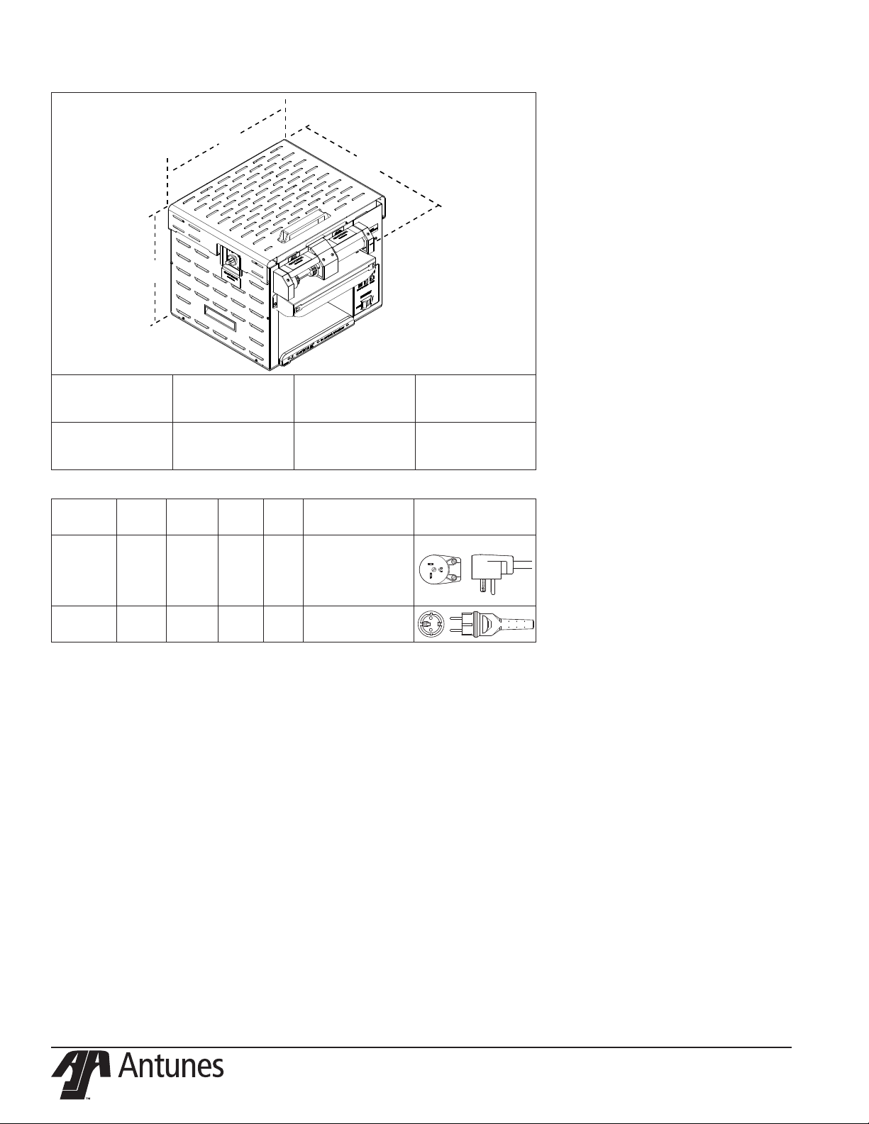
Silicone
Belt
Release
Sheet
Release
Sheet
Bracket
Figure 1. Installing Release Sheet
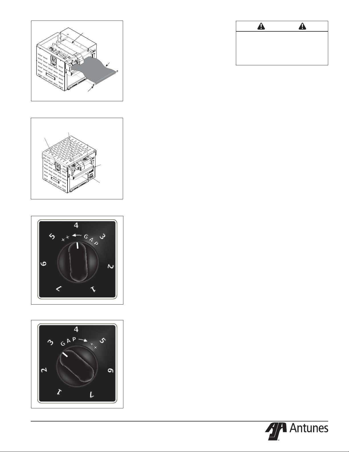
Crown Side
Bun Thickness
Adjustment Control
ONLY
Heel Side
ONLY
Control Panel/
Power Switch
Bun Load
Platform
Figure 2. HCT-2010 Toaster
Figure 3. Crown Setting
Figure 4. Heel Setting
P/N 1011236 Rev. C 04/16
INSTALLATION
1. Remove unit and all packing materials
from shipping carton.
2. The unit should come with the items
listed below:
• Bun Chute
• Bun Load Platform and Release
Sheet Retainer
• Three Release Sheets
• Owner’s Manual and Authorized
Service Agency Directory
NOTE: If any parts are missing or damaged, contact Antunes Technical Service
IMMEDIATELY at 1-877-392-7854 or
1-630-784-1000.
3. Remove all packing materials and
protective coverings from the unit.
4. Wipe all surfaces of the unit with a
hot damp cloth.
NOTE: Do NOT use a dripping wet cloth.
Wring out before use.
When placing the toaster into service, pay
attention to the following guidelines.
• Make sure the power switch is off and
the unit is at room temperature before
plugging in the power cord.
• Do not block or cover any openings
on the unit.
• Do not immerse the power cord or
plug in water.
• Keep the power cord away from
heated surfaces.
• Do not allow the power cord to hang
over edge of table or counter.
• Provide 1” clearance on the sides and
rear of the unit to prevent any damage to nearby walls and materials.
Plug the power cord into the appropriate
power outlet. Refer to the specification
plate for the proper voltage.
1. Place the unit on a flat, sturdy location.
2. Install the Bun Chute.
3. Attach the Bun Load Platform to the
front of the unit.
4. Install the Release Sheet onto the
Release Sheet Bracket and hang the
Release Sheet Bracket onto the Bun
Load Platform. Turn the unit on and
allow the Conveyor Belt to draw the
sheet into the unit. Turn the unit off.
IMPORTANT: Do not plug any other power
cords into the receptacles on the toaster.
5. Install the Top Cover and Heat Shield.
5
CAUTION
Bread may burn. Therefore toasters must
not be used near or below curtains or other
combustible walls and materials. Failure to
maintain safe operating distances may cause
discoloration or combustion.
OPERATING INSTRUCTIONS
NOTE: The unit includes a Bun Thickness
Adjustment Control that is factory set.
The recommended Bun Thickness setting
is 4 for CROWN (Figure 3) and 3 for HEEL
(Figure 4).
1. Turn on the power and allow the unit to
warm up for 30 minutes.
The temperature display flashes “LO” until the
toaster reaches its preset operating temperature. When the toaster approaches the preset
temperature of 570°F (293°C), “USE” appears
in the temperature display and the unit is
ready to toast buns. If “USE” does not appear
in the window after approximately 30 minutes, contact your Authorized Service Agency.
2. Insert Crowns and Heels cut side
DOWN across the Bun Load Platform
and into the toaster (Figure 2).
NOTE: Observe the CROWN and HEEL
labels on the front of the unit for proper
toasting. Insert buns cut side DOWN.
3. Toasted buns will drop out of the
unit and down the Bun Chute after
approximately 16 seconds.
4. Test at least four buns before putting
the toaster into service.
5. Turn the unit off when finished toasting for the day and proceed with
the Daily Cleaning as outlined in the
Maintenance section of this manual.
Page 6
LIGHT/DARK ADJUSTMENTS
The light/dark value can be adjusted when the
unit is displaying “LO” or “USE”. To adjust
the light/dark value, press the LIGHTER or
DARKER button. The display will change to
show the current light/dark value.
NOTE: The default light/dark value is d0.
Press the LIGHTER or DARKER button to
change the light/dark value. The adjustment
range is L1-L9 and d0-d9. L9 is the lightest, d0
is the middle, and d9 is the darkest setting.
To save the light/dark value, press the
PROGRAM button or wait 5 seconds until the
screen displays “LO” or “USE”.
NOTE: Adjusting the light/dark value does
NOT change the temperature. It changes
the speed of the conveyors. The light/dark
value will reset to the d0 value when the
unit is turned off.
USER MODE
User Mode allows an operator to view the
toaster settings but does not permit any
adjustments.
1. Press and hold the PROGRAM button
for 5 seconds. After 5 seconds, the display will show the actual temperature
of the Platen Heater.
2. Press the LIGHTER button to view the
setpoint of the Platen Heater.
3. Press the PROGRAM button to proceed to the Auxiliary Heater menu. The
display will show the actual temperature of the Auxiliary Heater.
4. Press the LIGHTER button to view the
setpoint of the Auxiliary Heater.
5. Press the PROGRAM button to proceed to the Motor Menu. The display
will show the actual speed of the
motor.
6. Press the LIGHTER button to view the
setpoint of the motor.
NOTE: The unit will exit User Mode after 5
seconds of keypad inactivity.
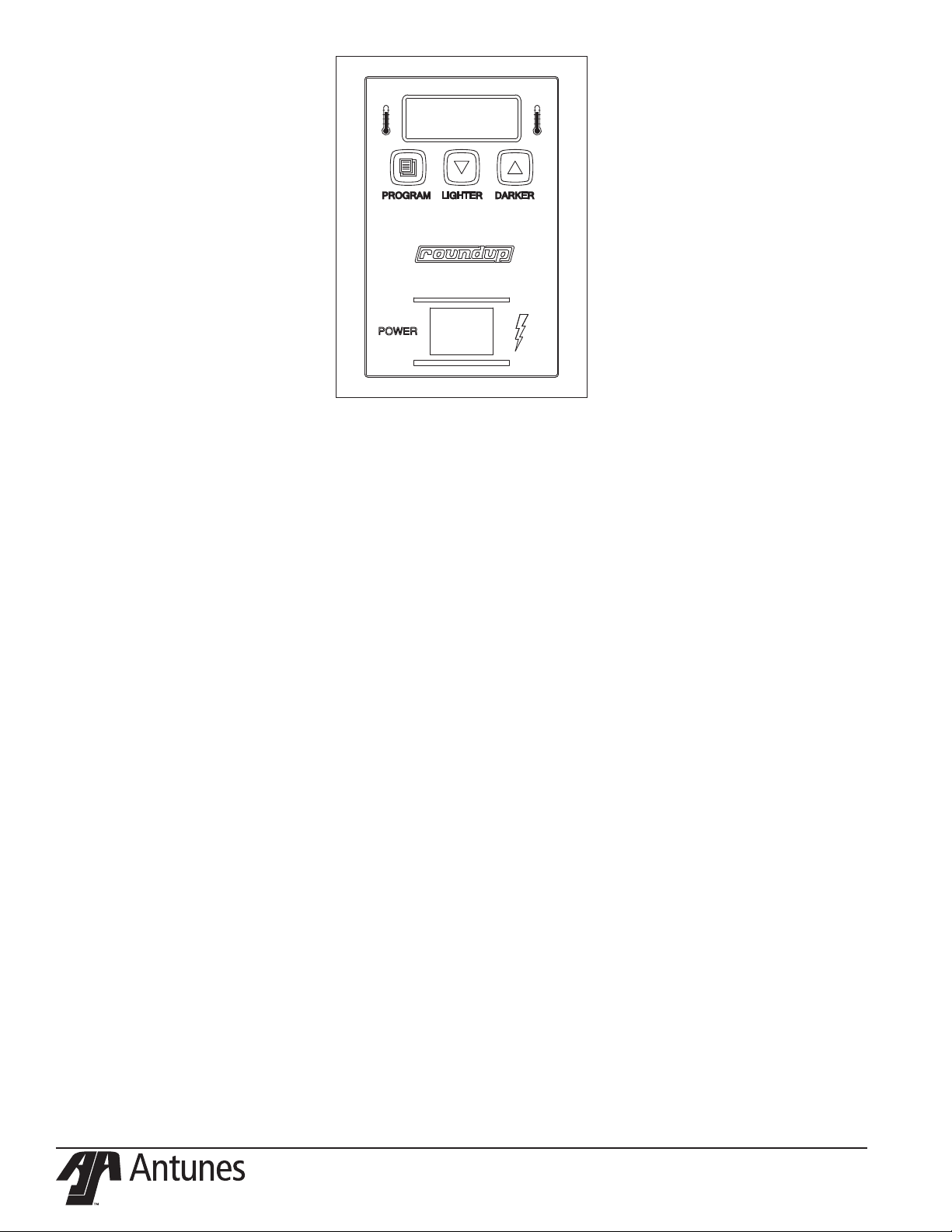
PROGRAM
LIGHTER
DARKER
Figure 5. Toaster Control Panel
MANAGER MODE
Manager Mode allows an operator to view
and adjust the following settings:
• Platen Heater Temperature
• Auxiliary Heater Temperature
• Motor Speed
• Temperature Units
Manager Mode also allows an operator to
view (but not adjust) the Ambient Temperature
of the Control Compartment..
1. Turn the unit off.
2. Turn the power on while holding the
PROGRAM button. Continue to hold
the button until “ENA” appears on
the display (after approximately 10
seconds).
3. Release the PROGRAM button. The
display now shows the Platen Setpoint
Temperature.
4. To adjust the Platen Setpoint, press
the LIGHTER or DARKER buttons to
reach the desired temperature.
NOTE: The recommended temperature
setting for the Platen Heater is 570°F
(299°C).
5. Press the PROGRAM button to proceed to the Auxiliary Heater Setpoint
Temperature.
6. To adjust the Auxiliary Heater Setpoint,
press the LIGHTER or DARKER but-
tons to reach the desired temperature.
NOTE: The recommended temperature
setting for the Auxiliary Heaters is 360°F
(166°C).
7. Press the PROGRAM button to proceed to the Motor Speed Setpoint.
8. Adjust the Motor Speed Setpoint by
pressing the LIGHTER or DARKER
buttons to reach the desired speed.
NOTE: The Motor Speed is adjustable from
1-100. The recommended setting is 85.
9. Press the PROGRAM button to proceed to Temperature Units.
10. To change the Temperature Units
from Fahrenheit or Celsius, press the
LIGHTER or DARKER button.
11. Press the PROGRAM button to proceed to the Ambient Temperature of
the Control Compartment.
NOTE: No changes can be made to the
Ambient Temperature of the Control
Compartment. Temperatures under 150°F
(66°C) are acceptable.
12. Press and hold the PROGRAM button
to save any changes.
NOTE: The unit will exit Manager Mode
after 30 seconds of keypad inactivity.
6
P/N 1011236 Rev. C 04/16
Page 7

SAFETY FEATURES
ERROR CODES
A Hi-Limit Control turns off electric power
to the heaters and control circuits if the unit
overheats. To reset the control, allow 10-15
minutes for the unit to cool, then locate
the Hi-Limit Control on the rear of the unit.
Remove the black protective cap, press the
button, and reinstall the protective cap.
NOTE: If the Hi-Limit Control requires continuous resetting, contact your Authorized
Service Agency.
FAULT MESSAGES
The Control Display will flash fault messages
when there is a problem with the unit.
“HI” will flash if the Platen Heater temperature is 30°F more than the setpoint or if the
Platen Thermocouple is disconnected or open.
“HI” and “USE” will flash if the Auxiliary
Heater temperature is 50°F more than the
setpoint or if the Auxiliary Thermocouple is
disconnected or open.
“CHEC” will flash when the control compartment ambient temperature is more than 150°C
(66°C). All heaters will shut off. The unit will
not restart until the control compartment
ambient temperature falls below 140°F (60°C).
If any of the following Error Codes appear, turn
the power off, allow the unit to cool, and turn
the power back on. If the error repeats, contact
your Authorized Service Agency for assistance.
ERR 1: Internal error. Cycle the Power Switch.
If error persists, replace the board.
ERR 2: Internal error. Cycle the Power Switch.
If error persists, replace the board.
ERR 3: Internal error. Cycle the Power Switch.
If error persists, replace the board.
ERR 4: Invalid DIP Switch setting. The only
approved setting is (left to right) upup-up-down (1 on; 2, 3, 4 off).
ERR 5: Internal error. Cycle the Power Switch.
If error persists, replace the board.
ERR 6: Internal error. Cycle the Power Switch.
If error persists, replace the board.
ERR 7: Not used.
ERR 8: Shorted Platen Thermocouple.
ERR 9: Open Platen Thermocouple.
“PO” will flash if the incoming power drops
below 190 volts. The toaster will shut down.
“StoP” will flash when the motor has stopped
for seven continuous seconds.
“SpEd” will flash when the motor speed has
dropped 25% below the setpoint for 30 continuous seconds.
P/N 1011236 Rev. C 04/16
7
Page 8
WARNING
Turn the power off, unplug the power cord, and
all the unit to cool down for 30 minutes before
performing any service or maintenance.
WARNING
To prevent damage to the unit, do not use
abrasive cleaners on the Release Sheet or
Silicone Belts.
WARNING
Failure to use Release Sheets may result in
damage to the unit and loss of warranty
coverage.
DAILY MAINTENANCE
AT CLOSE
• Turn the unit OFF and unplug at the
outlet. Allow unit to cool.
• Remove the Release Sheet Retainer
and Release Sheet. Fill a full-sized pan
with hot Detergent Solution and place
Release Sheet into pan to soak.
• Take The Release Sheet Retainer and
Bun Load Platform to the dishwashing
sink. Hand wash, rinse; then sanitize
for a minimum of 60 seconds. Allow
to air dry. Return to service line; set
aside for reassembly at open.
AT OPEN
• Make sure unit is off and unplugged
at the outlet.
• Remove the Release Sheets.
• Fill a full-size pan with hot Detergent
Solution and place Release Sheet into
pan to soak.
• Remove the Heat Shield and Top
Cover and on-line clean the Silicone
Belts. Do NOT submerge.
• Remove the Bun Chute and take to
dishwashing sink.
NOTE: Do NOT place parts into the powerwash sink.
• Pre-rinse, hand wash, rinse and sanitize parts. Return parts to service line.
• Fill a clean 1/6-size, 6-inch deep s/s
pan with hot Detergent Solution; a second pan with clean rinse water; and a
third pan with Sanitizer Solution. Place
a clean, white towel in each pan and
place near toaster.
• Wipe the Bun Load Platform.
• Wipe both sides of the Silicone Belts
(side facing out first) with a clean,
white towel and hot Detergent
Solution. Rinse with a clean, white
towel and clean rinse water. Sanitize
using a clean, white towel and
Sanitizer Solution.
• Rotate Belt around so the side facing
inward is facing out, exposing the
soiled areas of the Silicone Belt. Wash,
rinse, and sanitize following the above
step.
• Remove Release Sheet that has been
soaking and take to dishwashing sink.
Hand wash, rinse, and sanitize both
sides. Return to service line.
• Wipe outside of toaster with a clean,
white towel and hot Detergent
Solution.
• Reinstall the Bun Chute, Top Cover,
Heat Shield, and Bun Load Platform.
Install the Release Sheet.
NOTE: Rotate sheet daily from brown to
gold side.
• Install the Heat Shield. Plug unit in.
• Turn toaster ON 30 minutes prior to
opening.
NOTE: Check the Release Sheet to make
sure it is not caught in the Conveyor.
Additional Release Sheets can be purchased under P/N 7000798 (3-Pack).
8
P/N 1011236 Rev. C 04/16
Page 9

INCORRECT
CORRECT
Silicone
Belt Teeth
Silicone Belt Flap
Figure 6. Removing Silicone Belt
REPLACING THE RELEASE
SHEET (EVERY 3-5 WEEKS)
NOTE: Depending on toaster usage and on
how well it is cleaned daily, the Release
Sheet should last between 21–35 days.
1. Turn the power off, unplug the power
cord, and allow the unit to cool.
2. Remove the Release Sheet Bracket.
Discard the old Release Sheet. Keep
the Bracket.
3. Slide the Release Sheet Bracket
through the end of the new Release
Sheet (Figure 1).
4. Hang the Release Sheet Bracket onto
the Bun Load Platform. Insert the loose
end of the Release Sheet into the
toaster (Figure 1). Turn the unit on and
allow the Conveyor Belt to draw the
Release Sheet into the unit. Turn the
unit off.
REPLACING THE SILICONE
BELTS (EVERY 2–4 MONTHS)
NOTE: The Silicone Belts should last 2–4
months. Additional Silicone Belts may be
purchased from your Authorized Service
Agency.
1. Turn the unit off, unplug the power
cord, and allow the unit to cool. Set
the Bun Thickness Adjustment Control
to 7 and 7.
2. Put on Heat Resistant gloves and
remove the Top Cover and Heat Shield.
3. Make sure flap of the Silicone Belt is
accessible on the top side. Pull the
Silicone Belt Pins out of the zipper on
the Silicone Belts (Figure 6).
P/N 1011236 Rev. C 04/16
Figure 7. Aligning Belt Teeth
4. Face the front of the toaster. Push the
front of the conveyor IN and DOWN so
it locks into place. This will release the
belt tension and allow it to be free.
5. Remove and discard the old Silicone
Belt(s).
6. Wipe the Conveyor Belt Chain with a
clean towel dampened sanitizer and
allow to air dry.
7. Install the new Silicone Belts in the
front of the toaster above the Platen.
Wrap the Silicone Belts around the
Conveyor Belt Chain with the zipper
flap exposed to the REAR of the unit
(Figures 6 and 7).
NOTE: Align the edges of the Silicone Belt
properly (Figure 7) or the Silicone Belt
may be damaged.
WARNING
Align the ends of the Silicone Belt properly
(Figure 7) or the belt may be damaged.
WARNING
The unit can retain heat. Be sure to wear HeatResistant Gloves to avoid personal injury.
8. Secure the Silicone Belts with the Belt
Pins.
9. Set the Bun Thickness Adjustment
Control to the correct operating setting.
10. Reassemble the unit and test before
returning to service.
ABOUT THE HTC-2010 CLIP
STYLE BELT
The HCT-2010 Silicone Belts have been updated to clip onto the wire conveyor belts and
connect together using the standard belt pin.
For information on installing these new style
belts, refer to Page 20 for complete instructions.
9
Figure 8. Chain Tensioner Guide
CHECKING THE CONVEYOR
BELT CHAINS
(EVERY 3–6 MONTHS)
NOTE: Make sure the Bun Thickness
Adjustment Control is set to the desired
operating setting.
NOTE: The Chain Tensioner Guide is
included with replacement belt kit
7001205.
MEASURING CONVEYOR BELT CHAINS
1. Turn the unit off, unplug the power
cord, and allow the unit to cool. .
2. Put on Heat Resistant gloves and
remove the Top Cover and Heat Shield.
3. Make sure flap of the Silicone Belt is
accessible on the top side. Pull the
Silicone Belt Pins out of the zipper on
the Silicone Belts (Figure 6).
4. Unplug and remove the Butter Wheel
Assembly (Figure 2).
5. Face the front of the toaster. Push the
front of the conveyor IN and DOWN so
it locks into place. This will release the
belt tension and allow it to be free.
6. Remove the Silicone Belt(s).
7. Locate the center of the Crown side
Conveyor Chain. Pull up on the chain
to test the slack.
8. Place the Chain Tensioner Guide
(Figure 8) between the chain and the
frame of the toaster to verify the chain
is at the proper tension. If not, remove
links as needed to meet the proper
tension.
9. Repeat steps 7 and 8 for the Heel side
Conveyor chain to verify the chain is
at the proper tension.
10. If the chain is okay, reassemble the unit
and set the Bun Thickness Adjustment
Control to the normal settings.
Page 10

ADJUSTING CONVEYOR BELT CHAIN
REPLACING CONVEYOR BELT CHAIN
1. Turn the unit off, unplug the power
cord, and allow the unit to cool. Put
on Heat Resistant gloves and remove
the Top Cover and Heat Shield.
2. Make sure flap of the Silicone Belt is
accessible on the top side. Pull the
Silicone Belt Pins out of the zipper on
the Silicone Belts (Figure 6).
3. Unplug and remove the Butter Wheel
Assembly (Figure 2).
4. Face the front of the toaster. Push the
front of the conveyor IN and DOWN
so it locks into place. This will release
the belt tension and allow it to be
free.
5. Remove the Silicone Belt(s).
6. Remove one complete link from
Conveyor Belt Chain.
7. Replace the Silicone Belt(s). Secure with
the Belt Pin.
8. Reassemble the unit.
1. Turn the unit off, unplug the power
cord, and allow the unit to cool.
2. Put on Heat Resistant gloves and
remove the Top Cover and Heat
Shield.
3. Make sure flap of the Silicone Belt is
accessible on the top side. Pull the
Silicone Belt Pins out of the zipper on
the Silicone Belts (Figure 6).
4. Unplug and remove the Butter Wheel
Assembly (Figure 2).
5. Face the front of the toaster. Push the
front of the conveyor IN and DOWN
so it locks into place. This will release
the belt tension and allow it to be
free.
6. Remove the Silicone Belt(s).
7. Disengage the Conveyor Belt Chain
from both sides (Figure 9b)
8. Remove the Conveyor Belt Chain from
the unit.
9. Install the new Conveyor Belt Chain. The
chain MUST be installed with the hooks
facing the direction of travel. See Figure
9a.
10. Reassemble the unit.
BELT
STRAND
DISCONNECT THE BELT CHAIN
USING NEEDLE-NOSE PLIERS
TO BEND LINK AS SHOWN.
CONNECT THE BELT CHAIN
USING NEEDLE-NOSE PLIERS
TO BEND LINK AND LOOP
UNDER THE NEXT LINK
Conveyor Chains MUST
be installed with hooks
facing the direction of
travel (front to back)
Figure 9a. Conveyor Chain (FRONT of toaster view)
Large Arrows indicate direction of Belt Chain Travel
Heel Side
Conveyor Chain
Center Support
Cover
COMPLETED
INSTALLATION
Figure 9b. Disconnecting Conveyor
Chain
Crown Side
Conveyor Chain
10
P/N 1011236 Rev. C 04/16
Page 11

TROUBLESHOOTING
Problem Possible Cause Corrective Action
Control Display flashes “LO” continuously. Buns not toasting properly.
Control Display flashes “LO” continuously. Buns burn.
Control Display flashes “PO” continuously.
Control Display flashes “CHEC” continuously.
Control Display flashes “HI” continuously. Buns burn.
Control Display flashes “ERR 9” continuously. Buns not toasting properly.
Control Display flashes “HI” and
“USE” after 20–30 minutes.
Control Display flashes “StoP”. Mechanical bind in one or both conveyors. Enter User Mode to check the motor speed.
Control Display flashes “SpEd”. Mechanical bind in one or both
Platen temperature is below 440ºF (226ºC). Allow the unit to warm up for 30 minutes and then
recheck. If the Control Display still reads “LO”, contact your maintenance person or Authorized Service
Agency for service.
Failed Platen Thermocouple. Contact your maintenance person or Authorized
Failed Control Board.
The power to the unit is below 190 volts. Turn the power off and then on. If the display still
Failed Control Board.
Failed Transformer.
Control Compartment ambient temperature is above
140ºF (60ºC).
Failed Cooling Fan.
Failed Control Board.
Failed Platen Solid State Relay. Contact your maintenance person or Authorized
Failed Control Board.
Failed Platen Thermocouple.
Loose Platen Thermocouple connection on Control
Board or the Platen Thermocouple is open.
Failed Control Board.
Loose Auxiliary Thermocouple connection on Control
Board or Auxiliary Thermocouple is open.
Faulty Auxiliary Solid State Relay. Contact your maintenance person or Authorized
Damaged ball bearings.
Conveyor chains loose or damaged.
Drive chain or sprockets damaged.
Motor has shortened tachometer.
Motor is not receiving voltage.
conveyors.
Damaged ball bearings.
Conveyor chains loose or damaged.
Drive chain or sprockets damaged.
Service Agency for service.
shows “PO”, check the power cord, plug, and outlet
for damage.
Reset the Circuit Breakers.
Contact your maintenance person, Authorized
Service Agency, or electrician for service.
Verify side vents on toaster are unblocked and not
near other heating appliances. If problem still persists, contact your maintenance person or
Authorized Service Agency for service.
Service Agency for service.
Re-secure the Platen Thermocouple connection to
the Control Board. If the Control Display still reads
“ERR 9”, check the Thermocouple for continuity.
Contact your maintenance person or Authorized
Service Agency for service.
Re-secure the Auxiliary Thermocouple connection to
the Control Board. If the Control Display still reads
“HI” and “USE”, check Thermocouple for continuity.
Contact your maintenance person or Authorized
Service Agency for service.
Service Agency for service.
Check both conveyors for mechanical binds.
Test the motor.
Replace necessary parts.
Contact your maintenance person or Authorized
Service Agency for service.
Enter User Mode to check motor speed.
Check both conveyors for mechanical binds.
Replace necessary parts.
Contact your maintenance person or Authorized
Service Agency for service.
P/N 1011236 Rev. C 04/16
11
Page 12

TROUBLESHOOTING (continued)
Problem Possible Cause Corrective Action
No Control Display. Power cord not plugged in. Plug power cord into the proper electrical outlet.
Hi-Limit Control has tripped. Allow unit to cool and reset the Hi-Limit Control. If
it trips again, contact your maintenance person or
Authorized Service Agency.
Circuit Breakers turned off or tripped.
Damaged electrical outlet, plug, or cord.
Power Switch damaged.
Faulty Transformer. Replace Transformer.
Conveyor does not turn. Damaged or Missing Roller Tensioner. Adjust or replace Roller Tensioner.
Conveyor Belt/Chain has stretched. Chain skipping
on sprockets.
Motor Drive Chain came off Sprocket(s). Reinstall Drive Chain.
Drive Chain needs lubrication. Lubricate chain with Lubit-8 (P/N 2190152).
Drive Motor has failed. Contact your maintenance person or Authorized
Buns not toasting adequately. Compression Settings are incorrect. Use the recommended settings.
Temperature Setting is incorrect. Verify that the Platen (SP-P) is set to 570°F (297°C)
Release Sheet is worn or needs cleaning (replace
every 3–5 weeks).
Silicone Belts are worn or need cleaning (replace
every 2–4 months).
Silicone Belts are not tacky/sticky. Replace or clean Silicone Belts as described in the
Buns do not meet specifications. Contact your bun supplier.
Reset Circuit Breakers. If they trip again, check the
power cord, plug, and outlet for damage.
Contact your maintenance person, Authorized
Service Agency, or electrician for service.
Measure and adjust the Conveyor Belt Chains
as described in the Maintenance section of this
manual.
Service Agency for service.
and the Auxiliary (SP-A) is set to 330°F (166°C). For
making changes to the setpoint temperature, see
the Installation section of this manual.
Inspect Release Sheet for cleanliness, worn sports,
tears, or wrinkles. Clean or replace Release Sheet
as described in the Maintenance section of this
manual.
Replace or clean Silicone Belts as described in the
Maintenance section of this manual.
Maintenance section of this manual.
12
P/N 1011236 Rev. C 04/16
Page 13

TROUBLESHOOTING (continued)
Problem Possible Cause Corrective Action
Crowns and/or Heels must be forced
into the toaster. Buns sticking and
burning.
New Silicone Belts do not fit. Compression Settings are incorrect. Set Bun Thickness Compression Knobs to 1 when
Toaster makes unusual sounds. Compression Settings are too tight. Set Bun Thickness Compression Knobs to the
Silicone Belts not being cleaned properly. Clean Silicone Belts as described in the
Maintenance section of this manual.
Silicone Belts are not tacky/sticky (replace every 2–4
months).
Silicone Belts are dirty, worn, or damaged (replace
every 2–4 months).
Release Sheet is not being cleaned properly. Clean both sides of the black and silver Release
Release Sheet is not being reversed as required. Reverse the Release Sheet or replace Release Sheet
Release Sheet is dirty, worn, or damaged (replace
every 3–5 weeks).
Conveyor Belt Chains are skipping on Sprockets. Measure and adjust the Conveyor Belt Chains as
Silicone Belts slipping over Conveyor Belt Chains. Remove Silicone Belts and clean the Conveyor Belt
Drive Motor stalls intermittently. Contact your maintenance person or an Authorized
Compression Settings are incorrect. Use the recommended settings.
Buns are not inserted into the toaster properly. Buns must be inserted with the cut sides facing
Silicone Belts not installed correctly. Install Silicone Belts between the Support Rods with
Silicone Belts are damaged or are the wrong type for
your unit.
Silicone Belts are installed incorrectly. Silicone Belts must be installed as described in the
Silicone Belt Pin rubbing on housing. Center the Pin in the Silicone Belt zipper.
Conveyor Belt Chains have stretched. Measure and adjust the Conveyor Belt Chains as
Conveyor Belt Chains adjusted incorrectly.
Sugar and/or carbon has accumulated inside the
Silicone Belt and between the Conveyor Belt Chain
and Tensioner Slide Rails.
Motor Drive Chain needs lubrication. Lubricate the Drive Chain carefully with Lubit-8 (P/N
A Conveyor Shaft bearing is binding. Contact your maintenance person or Authorized
Clean Silicone Belts. If the Silicone Belts are too
worn, replace them as described in the Maintenance
section of this manual.
Clean or replace Silicone Belts as described in the
Maintenance section of this manual.
Sheet as described in the Maintenance section of
this manual.
as described in the Maintenance section of this
manual.
Clean or replace the Release Sheet as described in
the Maintenance section of this manual.
described in the Maintenance section of this
manual.
Chain links and Silicone Belts as described in the
Maintenance section of this manual.
Service Agency for service.
down on the correct Heel or Crown side.
replacing Silicone Belts or when adjusting Conveyor
Belt Chains.
the zipper flap exposed and facing up.
Replace with OEM P/N 7000897 only.
correct (or larger) setting.
Maintenance section of this manual.
described in the Maintenance section of this
manual.
Remove Silicone Belts, clean Conveyor Belt Chain
links just as you clean the Silicone Belts daily, and
then clean the Slide Rails on the Tensioners. Next,
clean the Silicone Belt on both sides before
reinstalling it.
2140152) at least once a year.
Service Agency for service.
P/N 1011236 Rev. C 04/16
13
Page 14

REPLACEMENT PARTS
Located Next
2
4
1
3
10
11
12
13
38
7
8
9
70
40
16
15
27
69
42
46
49
51
50
48
14
17
31
70
9
20
47
52
30
18
37
33
13
12
32
10
76
8
28
For Mfg. No.
9210316
29
7
81
35
11
10
100
21
23
27
19
34
36
26
101
23
22
24
25
24
22
2
82
102
53
54
28
76
30
14
For Mfg. No.
9210317
103
106
P/N 1011236 Rev. C 04/16
Page 15

REPLACEMENT PARTS
Item Part No. Description Qty. Item Part No. Description Qty. Item Part No. Description Qty.
1 0506248 Top Heat Shield 1
2 2100253 1/4 Shaft Knob 2
3 0012628 End Housing Cover Assy. 1
4 1001418 Compression Label 1
End Housing
5 1001419 Label, Crown 1
6 1001420 Label, Heel 1
7 7000825 Tension Spring Kit, 4-Pack 8 2150317 Cam 4
9 0506244 Right Cam Bracket 2
10 308P143* Hex Nut #8-32 11 0506067 Bearing Retainer 2
12 2150285 Single Groove Bearing 6
7000777 Bearing, Two-Pack 13 0504320 Spacer, .781” x 1.125” 6
14 7000542 Rocker Switch, 250VAC 1
Green Indicator
15 1001390 Control Label 1
16 4051005 Receptacle, 250VAC, 15A 1
17 7000948 Control Board Kit 1
(Incl. #52)
18 0012627 Control Housing Cover 1
19 1001423 Compression Label 1
Control Housing
20 2110197 Steel Clip 2
21 0012630 Drive Motor Assy. 1
(Incl. #24)
22 2150320 Chain, HCT 1
23 2150181 1/2” Bore Sprocket 1
24 2150295 .395 Bore Sprocket 1
25 7000819 Chain and Sprocket Kit 1
(Incl. #22, 23 & 24)
26 7000820 Hardware Kit 1
(Incl. #10, 11, 12, 13, 23,
100 & 101)
27 308P203 Screw, #8-32 with Washer 28 4051010 Solid State Relay, 50A 1
29 4010187 Transformer, 240V 1
30 4010221 Cap-MP, Motor Run 1
31 1001421 Wiring Diagram 1
(not shown)
32 4070154 Varistor Board 1
33 4060355 Terminal Block, 3-Pole 1
34 4000201 Axial Fan, 200/230V 1
35 4030332 Hi-Limit Thermostat 1
36 7000810 Thermocouple, Type K 1
3/16” Dia.
37 0400354 90° Strain Relief Elbow 1
38 0700737 Power Cord Assy. 1
250V, 20A (9210316 only)
0700543 Power Cord Assy.
250 V, 16A (9210317 only)
39 7000809 Platen Kit 208 VAC 1
(9210316 only)
7000873 Platen Kit 230 VAC 1
(9210317 only)
40 7000934 Bun Load Platform 1
and Retainer Kit
42 0506221 Release Sheet Bracket 1
43 212P220* Spacer, .50” 44 325P104* Flat Washer, 1/4” 45 325P195* Mach. Screw, 1/4”-20 46 7000812 Outer Base Kit 208 VAC 1
(9210316 only)
7000853 Outer Base Kit 230 VAC 1
(9210317 only)
47 308P157* Screw, #8-32 x 3/8” 48 0506232 Base Inner 1
49 0900297 Bun Stop 1
50 1001023 Label, Caution Hot 1
51 308P120* Mach. Screw, #8-32 x 5/8” 52 304P105* Hex Nut, #4-10 53 0200302 Base Gasket, 19.13” Lg. 2
54 0200301 Base Gasket, 14.26” Lg. 2
55 0012651 Top Cover Assy. 1
56 0800427 Wire Belt, Crown Side 1
57 0800429 Wire Belt, Heel Side 1
58 300P123* Retaining Ring 1
59 7000813 Tensioner Assy., 2-Pack 1
60 0506256 Heater Cover 2
61 0400419 Aux. Heater Insulation 2
62 7001205 Silicone Belt, 2-Pack 63 0506258 Thermocouple Bracket 4
64 4030425 Aux. Heater, 208 VAC 2
(9210316 only)
4030428 Aux. Heater 230 VAC 2
(9210317 only)
65 0506237 Bun Compression Plate 2
66 7000816 Slide Rail Kit 2
(Incl. #97 & 98)
67 7000815 Aux. Thermocouple Kit 1
68 7000798 Release Sheet, 3-Pack (not shown)
69 308P103* Mach. Screw, #8-32 x 1/4” -
70 7000827 Slider Plate Kit (2-Pack) 72 0506243 Cam Bracket, Left 2
73 040P119* Bushing, Shorty 5/8” 74 2150319 Cam Shaft, End Housing 1
75 7000814 Sprocket, 1/2” Bore Kit 1
Four Pack
76 3080203 Screw, #8-32 x 3/8” 46
77 2150318 Cam Shaft, Control 1
Housing
78 2150323 Drive Shaft 1
79 0021737 Center Support 1
80 0506259 Front Cover, Center Support 1
81 0506254 Back Door 1
82 0800425 Wire Bun Chute 1
83 0506262 Top Cover, Center Support 1
84 0021724 Bearing Bracket and 2
Spring Guide, Right
85 0506241 Tensioner Plate, Left 2
86 0021738 Idler Support Bracket, Left 1
87 7000817 Roller, 2-Pack 2
88 2150321 Idler Shaft, Small 2
89 0506261 Idler Support Cover, Right 1
90 0012623 Idler Bearing Assy., Right 2
(Incl. #92)
91 0012622 Idler Bearing Assy., Left 2
(Incl. #92)
92 0600141 Compression Spring 4
93 325P176* Screw, Flange Hex Head Cap
94 325P163* Screw, 1/4”-28 x 5/16” 95 7000818 Roller Sprocket Kit 1
96 0506260 Idler Support Cover, Left 1
97 308P181* Screw, #8-32 x 3/8” 98 308P145* Acorn Nut, #8-32 99 306P130* Hex Nut, #6-32 100 0504321 Spacer, .503” x .69” x .06” 1
101 2120164
102 0506367 Heat Sink (9210317 only) 1
103 4070170 Filter Board (9210317 only) 1
104 4050229 Line Filter (9210317 only) 1
105 306P104* Screw, Mach. #6-32 X 1/4” -
(9210317 only)
106 306P105* Screw, Mach. #6-32 X 1/2” -
(9210317 only)
* available in packs of 10.
Spacer, .503” x .69” x .359”
1
P/N 1011236 Rev. C 04/16
15
Page 16

REPLACEMENT PARTS
83
70
96
92
93
91
95
94
88
95
90
109
72
92
74
80
91
87
73
7
69
8
75
88
55
98
59
99
60
99
79
92
94
87
93
90
92
89
39
78
77
75
58
67
45
44
43
61
63
64
65
98
6
5
97
57
66
56
62
16
P/N 1011236 Rev. C 04/16
Page 17

REPLACEMENT PARTS
Item Part No. Description Qty. Item Part No. Description Qty. Item Part No. Description Qty.
1 0506248 Top Heat Shield 1
2 2100253 1/4 Shaft Knob 2
3 0012628 End Housing Cover Assy. 1
4 1001418 Compression Label 1
End Housing
5 1001419 Label, Crown 1
6 1001420 Label, Heel 1
7 7000825 Tension Spring Kit, 4-Pack 8 2150317 Cam 4
9 0506244 Right Cam Bracket 2
10 308P143* Hex Nut #8-32 11 0506067 Bearing Retainer 2
12 2150285 Single Groove Bearing 6
7000777 Bearing, Two-Pack 13 0504320 Spacer, .781” x 1.125” 6
14 7000542 Rocker Switch, 250VAC 1
Green Indicator
15 1001390 Control Label 1
16 4051005 Receptacle, 250VAC, 15A 1
17 7000948 Control Board Kit 1
(Incl. #52)
18 0012627 Control Housing Cover 1
19 1001423 Compression Label 1
Control Housing
20 2110197 Steel Clip 2
21 0012630 Drive Motor Assy. 1
(Incl. #24)
22 2150320 Chain, HCT 1
23 2150181 1/2” Bore Sprocket 1
24 2150295 .395 Bore Sprocket 1
25 7000819 Chain and Sprocket Kit 1
(Incl. #22, 23 & 24)
26 7000820 Hardware Kit 1
(Incl. #10, 11, 12, 13, 23,
100 & 101)
27 308P203 Screw, #8-32 with Washer 28 4051010 Solid State Relay, 50A 1
29 4010187 Transformer, 240V 1
30 4010221 Cap-MP, Motor Run 1
31 1001421 Wiring Diagram 1
(not shown)
32 4070154 Varistor Board 1
33 4060355 Terminal Block, 3-Pole 1
34 4000201 Axial Fan, 200/230V 1
35 4030332 Hi-Limit Thermostat 1
36 7000810 Thermocouple, Type K 1
3/16” Dia.
37 0400354 90° Strain Relief Elbow 1
38 0700737 Power Cord Assy. 1
250V, 20A (9210316 only)
0700543 Power Cord Assy.
250 V, 16A (9210317 only)
39 7000809 Platen Kit 208 VAC 1
(9210316 only)
7000873 Platen Kit 230 VAC 1
(9210317 only)
40 7000934 Bun Load Platform 1
and Retainer Kit
42 0506221 Release Sheet Bracket 1
43 212P220* Spacer, .50” 44 325P104* Flat Washer, 1/4” 45 325P195* Mach. Screw, 1/4”-20 46 7000812 Outer Base Kit 208 VAC 1
(9210316 only)
7000853 Outer Base Kit 230 VAC 1
(9210317 only)
47 308P157* Screw, #8-32 x 3/8” 48 0506232 Base Inner 1
49 0900297 Bun Stop 1
50 1001023 Label, Caution Hot 1
51 308P120* Mach. Screw, #8-32 x 5/8” 52 304P105* Hex Nut, #4-10 53 0200302 Base Gasket, 19.13” Lg. 2
54 0200301 Base Gasket, 14.26” Lg. 2
55 0012651 Top Cover Assy. 1
56 0800427 Wire Belt, Crown Side 1
57 0800429 Wire Belt, Heel Side 1
58 300P123* Retaining Ring 1
59 7000813 Tensioner Assy., 2-Pack 1
60 0506256 Heater Cover 2
61 0400419 Aux. Heater Insulation 2
62 7001205 Silicone Belt, 2-Pack 63 0506258 Thermocouple Bracket 4
64 4030425 Aux. Heater, 208 VAC 2
(9210316 only)
4030428 Aux. Heater 230 VAC 2
(9210317 only)
65 0506237 Bun Compression Plate 2
66 7000816 Slide Rail Kit 2
(Incl. #97 & 98)
67 7000815 Aux. Thermocouple Kit 1
68 7000798 Release Sheet, 3-Pack (not shown)
69 308P103* Mach. Screw, #8-32 x 1/4” -
70 7000827 Slider Plate Kit (2-Pack) 72 0506243 Cam Bracket, Left 2
73 040P119* Bushing, Shorty 5/8” 74 2150319 Cam Shaft, End Housing 1
75 7000814 Sprocket, 1/2” Bore Kit 1
Four Pack
76 3080203 Screw, #8-32 x 3/8” 46
77 2150318 Cam Shaft, Control 1
Housing
78 2150323 Drive Shaft 1
79 0021737 Center Support 1
80 0506259 Front Cover, Center Support 1
81 0506254 Back Door 1
82 0800425 Wire Bun Chute 1
83 0506262 Top Cover, Center Support 1
84 0021724 Bearing Bracket and 2
Spring Guide, Right
85 0506241 Tensioner Plate, Left 2
86 0021738 Idler Support Bracket, Left 1
87 7000817 Roller, 2-Pack 2
88 2150321 Idler Shaft, Small 2
89 0506261 Idler Support Cover, Right 1
90 0012623 Idler Bearing Assy., Right 2
(Incl. #92)
91 0012622 Idler Bearing Assy., Left 2
(Incl. #92)
92 0600141 Compression Spring 4
93 325P176* Screw, Flange Hex Head Cap
94 325P163* Screw, 1/4”-28 x 5/16” 95 7000818 Roller Sprocket Kit 1
96 0506260 Idler Support Cover, Left 1
97 308P181* Screw, #8-32 x 3/8” 98 308P145* Acorn Nut, #8-32 99 306P130* Hex Nut, #6-32 100 0504321 Spacer, .503” x .69” x .06” 1
101 2120164
102 0506367 Heat Sink (9210317 only) 1
103 4070170 Filter Board (9210317 only) 1
104 4050229 Line Filter (9210317 only) 1
105 306P104* Screw, Mach. #6-32 X 1/4” -
(9210317 only)
106 306P105* Screw, Mach. #6-32 X 1/2” -
(9210317 only)
* available in packs of 10.
Spacer, .503” x .69” x .359”
1
P/N 1011236 Rev. C 04/16
17
Page 18

WIRING DIAGRAM
AUX. HEATER #1
PLATEN HEATER
AUX. HEATER #2
BASE HEATER
AUX. HEATER #1
PLATEN HEATER
AUX. HEATER #2
BASE HEATER
For 9210316
BLK
BLK
MOV PCB
MOV1
#
TERMINAL
#
WIRE
∆ 14 GA
16 GA
*
18 GA
°
# 22 GA
ALL WIRES 105° C MINIMUM
UNLESS OTHERWISE NOTED
TERMINAL
BLOCK TB1
°
WHT
°
GRN/YEL *
22
TAB
WHT
POWER
POWER
CORD
BLK/BRN
1
7
BLK ∆
4
5
SWITCH
SW 1
GRN
WHT/BLU
3
2
8
WHT ∆
1
2
11
GRN-YEL
9
GRN/YEL
∆
700°F
WHT ∆
THERMOSTAT
WHT #
BUTTER WHEEL
PLUG
GRN/YEL *
6
CHASSIS
GND
2
1
HI-LIMIT
HL1
BLK #
BLK ∆
WHT #
L N
G
10
WHT *
ORG #
BRN
MOTOR
CAP
WHT *
BLK
12
WHT #
#
TEMP.
4
NC
NC
WHT #
2
654321
YEL
WHT
BLK
BLK #
CONTROL
8
7 6 5 4 3 2 1
NC
1
3
YEL #
°
J5
AUX
SSR
20
RED
J2
YEL
RED
J3
YEL
YEL
J6
17
RED #
18
ORG #
19
YEL #
43
+
-
240 VAC
12
BLK ∆
200°C
RED ∆
2
1 1 1 1
PLATEN
K-TYPE THERMOCOUPLES
AUX.
TR 1
+
240 VAC
22
-
BLK ∆
1
2
43
12
200°C
2
°
12 VAC
YEL
15
RED #
PLATEN
SSR
RED ∆
200°C
3
16
°
4
14
13
BLK 22GA
BLK #
WHT # 200°C
BLK #
°
J8
12 3
BLK #
RED #
5
BLK #
9
GRY
RED
BLK
BRN
M1
*
21
GRN/YEL
DRIVE MOTOR
2
1
F
FAN
WHT
WHT ∆ 200°C
°
For 9210317
MOV PCB
MOV1
23
CAP
BRD
#
TERMINAL
#
WIRE
∆ 14 GA
16 GA
*
18 GA
°
# 22 GA
ALL WIRES 105° C MINIMUM
UNLESS OTHERWISE NOTED
BLK
WHT
22
24
TAB
BLK
°
WHT
°
GRN/YEL *
BLK ∆
5
POWER
SWITCH
SW 1
POWER
CORD
BLK/BRN
1
7
LINE
FILTER
LOAD
25 26
4
GRN
WHT/BLU
3
2
8
WHT ∆
1
2
11
BUTTER WHEEL
GRN-YEL
TERMINAL
BLOCK TB1
9
GRN/YEL
∆
1
700°F
THERMOSTAT
WHT ∆
WHT #
PLUG
CHASSIS
GND
HI-LIMIT
HL1
BLK #
BLK ∆
GRN/YEL *
6
2
WHT #
L N
G
10
WHT *
ORG #
BRN
MOTOR
CAP
WHT *
BLK
12
WHT #
#
TEMP.
4
NC
NC
WHT #
2
654321
YEL
WHT
BLK
BLK #
CONTROL
8
7 6 5 4 3 2 1
NC
1
3
YEL #
°
J5
AUX
SSR
20
RED
J2
YEL
RED
J3
YEL
J6
17
RED #
18
ORG #
19
YEL #
43
+
-
240 VAC
12
200°C
RED ∆
2
1 1 1 1
WHT
PLATEN
K-TYPE THERMOCOUPLES
AUX.
YEL
°
12 VAC
YEL
15
RED #
PLATEN
SSR
BLK ∆
RED ∆
200°C
3
16
°
4
14
TR 1
+
240 VAC
22
-
BLK ∆
1
2
43
12
200°C
2
°
13
BLK 22GA
BLK #
WHT # 200°C
BLK #
°
J8
12 3
BLK #
RED #
5
BLK #
9
GRY
RED
BLK
BRN
M1
*
21
GRN/YEL
DRIVE MOTOR
2
1
F
FAN
WHT ∆ 200°C
18
P/N 1011236 Rev. C 04/16
Page 19

WIRING DIAGRAM (CONT)
WHT
BLK
HEATER
GND
GRN
BLK/BRN
WHT/BLU
GRN
GRN-YEL
POWER
CORD
WHT
BLK
ELEMENT
WIRING DIAGRAM
LIGHTED
Butter Wheel
P/N 1011236 Rev. C 04/16
19
Page 20

Installing the HCT Clip Style Belt
HTC-2010 CLIP STYLE BELT INSTRUCTIONS
With power off and toaster cool, remove top covers. Remove
current belts by either removing lacing pin or using scissors
1
or razor knife, carefully cut the belt free of the wire, drive belt.
Thread the clipped end of the belts under rear cover bar.
Position belts in the top middle of unit with clipped end
2
facing front and the length of belts draped over the rear of the
toaster.
With tension spring in run position install belts by hooking
back of each clip to wire belt and gently pulling end of belt
3
toward you while applying downward force to clip the front part
of the clip to the next metal wire.
Turn on toaster and let belts feed 1 revolution until the
belts are in the top center position again. Depress wire belt
4
tension springs in and down until they lock. Position both end of
belts together and line up so lacing is even. Insert the pin to join
both sides of belt together. Assure the clips are attached to the
wire belt.
P/N 1011207 11/12
Verify belt alignment is even from side to side of each belt.
Depress tension springs in and up to release from lock
5
position to run position. Verify belt alignment. Re-verify the
clips are attached to the wire belt. Replace top covers and start
toaster.
20
P/N 1011236 Rev. C 04/16
Page 21

NOTES
P/N 1011236 Rev. C 04/16
21
Page 22

NOTES
22
P/N 1011236 Rev. C 04/16
Page 23

NOTES
P/N 1011236 Rev. C 04/16
23
Page 24

LIMITED WARRANTY
Equipment manufactured by Roundup Food Equipment Division of A.J. Antunes & Co. has been constructed of the finest materials available and manufactured to high quality standards. These units are warranted to be free from electrical and mechanical
defects for a period of one (1) year from date of purchase under normal use and service, and when installed in accordance with
manufacturer’s recommendations. To insure continued operation of the units, follow the maintenance procedures outlined in the
Owner’s Manual. During the first 12 months, electro-mechanical parts, non-overtime labor, and travel expenses up to 2 hours (100
miles/160 km), round trip from the nearest Authorized Service Center are covered. During the first 24 months, coverage for parts
only to include the following components: Generator Casting, Solid State Control, and Motor.
1. This warranty does not cover cost of installation, defects caused by improper storage or handling prior to placing of the Equipment.
This warranty does not cover overtime charges or work done by unauthorized service agencies or personnel. This warranty does
not cover normal maintenance, calibration, or regular adjustments as specified in operating and maintenance instructions of this
manual, and/or labor involved in moving adjacent objects to gain access to the equipment. This warranty does not cover consumable/wear items. This warranty does not cover damage to the Load Cell or Load Cell Assembly due to abuse, misuse, dropping of
unit/shock loads or exceeding maximum weight capacity (4 lbs). This warranty does not cover water contamination problems such
as foreign material in water lines or inside solenoid valves. It does not cover water pressure problems or failures resulting from
improper/incorrect voltage supply. This warranty does not cover Travel Time & Mileage in excess of 2 hours (100 miles/160 km) round
trip from the nearest authorized service agency.
2. Roundup reserves the right to make changes in design or add any improvements on any product. The right is always reserved to
modify equipment because of factors beyond our control and government regulations. Changes to update equipment do not constitute a warranty charge.
3.
If shipment is damaged in transit, the purchaser should make a claim directly upon the carrier. Careful inspection should be made of the
shipment as soon as it arrives and visible damage should be noted upon the carrier’s receipt. Damage should be reported to the carrier.
This damage is not covered under this warranty.
4. Warranty charges do not include freight or foreign, excise, municipal or other sales or use taxes. All such freight and taxes are the
responsibility of the purchaser.
5. THIS WARRANTY IS EXCLUSIVE AND IS IN LIEU OF ALL OTHER WARRANTIES, EXPRESSED OR IMPLIED, INCLUDING ANY IMPLIED
WARRANTY OR MERCHANTABILITY OR FITNESS FOR A PARTICULAR PURPOSE, EACH OF WHICH IS HEREBY EXPRESSLY DISCLAIMED. THE REMEDIES DESCRIBED ABOVE ARE EXCLUSIVE AND IN NO EVENT SHALL ROUNDUP BE LIABLE FOR SPECIAL CONSEQUENTIAL OR INCIDENTAL DAMAGES FOR THE BREACH OR DELAY IN PERFORMANCE OF THIS WARRANTY.
 Loading...