

Page 1
Toaster
GST-5V
owner’s manual
Manufacturing Numbers:
9210880
Original Instructions
www.ajantunes.com
P/N 1011263 Rev. C 12/15
Page 2

CONTENTS
General 2
Warranty
Information 2
Service/Technical
Assistance 2
Important Safety
Information 3
Warnings 3
Specications 4
Dimensions 4
Electrical Specications & Plug
Conguration 4
Installation 5
Unpacking 5
Location 5
Language Selection 6
Operating
Instructions 6
Control Panel 6
Settings 6
Factory Reset 7
Adjusting Toast Quality 7
Maintenance 7
Daily Cleaning 7
Cleaning and Sanitizing the
Belts (Daily) 8
Replacing Belts (Quarterly) 11
Installing Belts 12
Cleaning the Top Cooling Fan
and Electrical Housing (Annually) 13
Cleaning the Rear Cooling Fan
and Electrical Housing (Annually) 13
Troubleshooting 14
Replacement Parts 18
Optional Accessory 18
Wiring Diagram 24
Notes 25
GENERAL
This manual provides the safety, installation,
and operating procedures for your toaster.
Please read all of the information contained
in this manual prior to installing and operating the toaster.
Your toaster is manufactured from the nest materials available and is assembled
to Roundup’s strict quality standards. This
toaster was tested at the factory to ensure
dependable trouble-free operation.
WARRANTY
INFORMATION
Please read the full text of the Limited Warranty in this manual.
If the unit arrives damaged, contact the
carrier immediately and le a damage claim
with them. Save all packing materials when
ling a claim. Freight damage claims are the
responsibility of the purchaser and are not
covered under warranty.
The warranty does not extend to:
y Damages caused in shipment or
damage as result of improper use.
y Installation of electrical service.
y Normal maintenance as out-
lined in this manual.
y Malfunction resulting from
improper maintenance.
y Damage caused by abuse
or careless handling.
y Damage from moisture into
electrical components.
Damage from tampering with, removal of,
or changing any preset control or safety
device.
SERVICE/TECHNICAL
ASSISTANCE
If you experience any problems with the
installation or operation of your system,
contact A.J. Antunes & Co. at 1-630-7841000, or toll free in the United States at
1-800-253-2991.
Fill in the information in the next column
and have it handy when calling for assistance. The serial number is on the specication plate located on the system.
Purchased From
Date of Purchase
Model Number
Serial Number
Mfg. Number
Use only genuine Roundup replacement
parts in this unit. Use of replacement parts
other than those supplied by the manufacturer will void the warranty. Your Authorized
Service Agency has been factory trained
and has a complete supply of parts for this
unit.
Visit www. ajantunes.com or contact the
factory at 1-630-784-1000 to locate your
nearest Authorized Service Agency.
Refer to the service agency directory
packaged with your manual and ll in the
information below.
Authorized Service Agency
Name
Phone Number
Address
2
P/N 1011263 Rev. C 12/15
Page 3

IMPORTANT SAFETY
INFORMATION
Use the following guidelines for safe operation of the unit.
y Read all instructions be-
fore using equipment.
y For your safety, the equipment is
furnished with a properly grounded
cord connector. Do not attempt to
defeat the grounded connector.
y Install or locate the equipment only
for its intended use as described in
this manual. Do not use corrosive
chemicals in this equipment.
y Do not operate this equipment if
it has a damaged cord or plug, if
it is not working properly, or if it
has been damaged or dropped.
y This equipment should be serviced
by qualied personnel only. Contact
your nearest Authorized Service
Agency for adjustment or repair.
y Do not block or cover any
openings on the unit.
y Do not immerse cord or plug in water.
y Keep cord away from heated surfaces.
y Do not allow cord to hang over
edge of table or counter.
y Turn the power o, unplug the
power cord, and allow unit to cool
down before performing any service
or maintenance on the unit.
y The equipment should be grounded
according to local electrical codes
to prevent the possibility of electri-
cal shock. It requires a grounded
receptacle with separate electrical
lines, protected by fuses or circuit
breaker of the proper rating.
y All electrical connections must be in
accordance with local electrical codes
and any other applicable codes.
y Do not clean this appli-
ance with a water jet.
y This appliance is not to be used by
persons (including children) with
reduced physical, sensory, or mental
capabilities, or lack of experience and
knowledge unless they have been
given supervision or instructions.
y Do not allow children to
play with the appliance.
WARNINGS
Be advised of the following warnings when
operating and performing maintenance on
this unit.
y If the supply cord is damaged, it must
be replaced by the manufacturer or
its service agent or a similarly qualied person in order to avoid a hazard.
y Do not modify the power sup-
ply cord plug. if it does not t the
outlet, have a proper outlet installed by a qualied electrician.
y Do not use an extension
cord with this appliance.
y Electrical ground is re-
quired on this appliance.
y Check with a qualied electri-
cian if you are unsure if the appliance is properly grounded.
y If a chemical cleaner is used, be
sure it is safe to use on cast aluminum. Observe all precautions
and warnings on product label.
y Inspection, testing, and repair
of electrical equipment should
only be performed by qualied service personnel.
y This equipment is to be installed to
comply with the basic plumbing code
of the Building Ocials and Code
Administrators, Inc. (BOCA) and the
Food Service Sanitation Manual of the
Food and Drug Administration (FDA).
y To ensure proper steaming character-
istics, some calcium/mineral deposits
must be present on the generator surface. If, during cleaning, the
surface does become free of calcium/
mineral deposits, add plain tap water
to the surface and allow it to boil o.
This may have to be repeated several
times to ensure proper steaming
characteristics by creating a thin
layer of deposits on the surface.
y Do not use a sanitizing solu-
tion or abrasive materials. The
use of these may cause damage
to the stainless steel nish.
y Chlorides or phosphates in clean-
ing agents (e.g. bleach, sanitizers,
degreasers or detergents) could cause
permanent damage to stainless steel
equipment. The damage is usually in
the form of discoloration, dulling of
metal surface nish, pits, voids, holes,
or cracks. This damage is permanent
and not covered by warranty.
y The following tips are recom-
mended for maintenance of your
stainless steel equipment:
y Always use soft, damp cloth for
cleaning, rinse with clear water and
wipe dry. When required, always rub
in direction of metal polish lines.
y Routine cleaning should be
done daily with soap, ammonia detergent, and water.
y Stains and spots should be sponged
using a vinegar solution.
y Finger marks and smears should be
rubbed o using soap and water.
y Hard water spots should be re-
moved using a vinegar solution.
P/N 1011263 Rev. C 12/15
3
Page 4
A
C
B
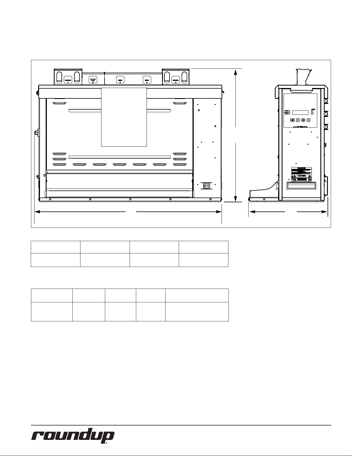
SPECIFICATIONS
Dimensions
Model &
Mfg. No.
GST-5V
9210880
Width
(A)
34.25 inches
(870 mm)
Depth
14.75 inches
(375 mm)
Electrical Specications & Plug Conguration
Model &
Mfg. No
GST-5V
9210880
(International)
Volt Watts Hz.
230 4600 50/60
(B)
Height
(C)
24.84 inches
(631 mm)
Plug
Description
IEC 309-Plug,
32 Amp., 230 VAC
Three Pin
4
P/N 1011263 Rev. C 12/15
Page 5
INSTALLATION
Unpacking
1. Open the large box. It contains:
• GST-5V toaster
• Accessories box
2. Remove the accessories box from the
large box.
3. With the help of another person,
carefully remove the GST-5V from
the large box.
4. Remove all protective coverings
from the unit.
5. Open the Accessories Box. It contains:
• Owner’s Manual
• Bun Buer Frame
6. Wipe the entire exterior of the
toaster and the accessories mentioned above with a clean towel
sprayed with an approved sanitizer.
Allow to air dry.
NOTE: Handle accessories with care. If
an accessory becomes bent or
damaged, it may not attach to
the unit correctly, which may affect normal operation.
NOTE: If any parts are missing or dam-
aged, contact A.J. Antunes Technical Service IMMEDIATELY at
1-877-392-7854 (North America
only), or 630-784-1000.
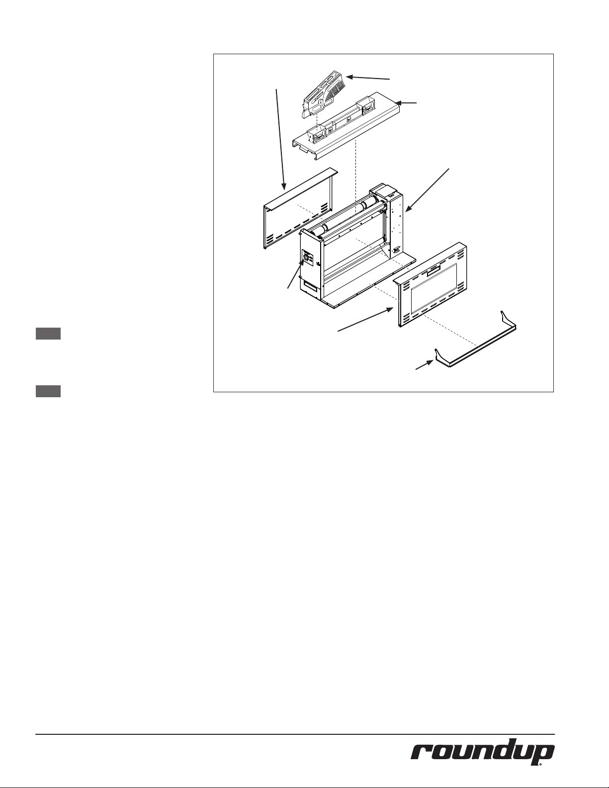
REAR
CONVEYOR
COVER
COMPRESSION
KNOB
OPTIONAL TOP FEEDER
AVAILABLE FOR PURCHASE SEPARATELY
BUN FEEDER
CONTROL
FRONT
CONVEYOR
COVER
BUN BUFFER
FRAME
Figure 1. GST-5V Components (Belts not Shown)
PANEL
Location
When placing the toaster into service, pay
attention to the following guidelines:
y Make sure power is o and the
toaster is at room temperature.
y Do NOT block or cover any
openings on the unit.
y Do NOT immerse cord
or plug in water.
y Keep cord away from heated surfaces.
y Do NOT allow cord to hang over
edge of table or counter.
1. Place the toaster in the required
position.
2. Attach the Bun Feeder and Bun Buffer Frame accessories (Figure 1).
3. Attach the optional Top Feeder if
present (Figure 1).
4. Plug the power cord into an appropriate power outlet. Refer to the
specication plate for
the proper voltage.
P/N 1011263 Rev. C 12/15
5
Page 6

Language Selection
Follow these steps to set the language option for the GST-5V toaster.
1. Plug in the power cord and turn the
toaster on.
2. See Figure 1. Press and hold the
MENU button for ve seconds.
3. Press the LEFT ARROW button ve
times so that the display shows
“English”.
4. Press the OK button.
5. Use the LEFT and RIGHT ARROW
buttons to select your preferred
language. The available
languages appear in the following
order:
• English
• Spanish
• French Canadian
• French
• German
• Portuguese
• Italian
• Swedish
• Russian
• Mandarin Chinese
• Japanese
6. Press the OK button to save the
changes.
7. Return the toaster to service.
DISPLAY
OPERATING
INSTRUCTIONS
The GST-5V toasts Crowns, Heels, Clubs, and
other products. Follow these steps to start
the GST-5V:
1. Turn on the toaster and wait for
warm-up to complete.
NOTE: The toaster fans turn on after
the A, B, or C Platen temperature
reaches 66°C (150°F).
2. Set the Compression Knob to 4
(recommended). If you use setting
5, refer to Table 1 (page 8) for the
required internal settings.
3. When the unit reaches operating
temperature, the control panel displays “Ready”.
4. Insert product into the designated
area of the Bun Feeder Assembly
with the cut side of the bun facing
towards the front. Toasted product
drops into the Bun Buer.
Control Panel
The control panel is located on the right side
of the unit. The LEDs on the control panel
light to signify when each item is operating.
The Service LED lights and the corresponding LED (Motor, A Platen, B Platen, C Platen)
blinks when the unit requires service. A
message also appears on the display.
Settings
Follow the steps below to view and adjust
the settings of the GST-5V.
1. When the unit is plugged in, press
and hold the MENU button (Figure
4) for ve seconds. The control panel
displays “A Platen.” The display scrolls
to show the actual temperature, SSR
Duty cycle, and the setpoint.
Example: A Platen: 271°C 35% 271°C
NOTE: The unit does not have to be
turned on in order to access the
settings menu.
2. Use the LEFT and RIGHT arrow but-
tons (Figure 4) to scroll through the
settings, which appear in the following order:
• A Platen
• B Platen
• C Platen
• Units (°C/°F)
• Buzzer (Soft, Loud, Mute)
• Display Languages
• ET (Elapsed Time)
• Controls Temperature
• Motor
3. To change a setting, press the OK
button and then use the LEFT and
RIGHT arrow buttons to adjust as
needed. Press the OK button again
to save the changes. See Figure 4.
NOTE: The Elapsed Time and Control
Temperature can not be adjusted.
The table below describes the settings for
the A Platen, B Platen, C Platen, and Motor
depending on the Compression Knob setting:
Compression
Setting #4
A Platen:
271°C (520°F)
B Platen:
271°C (520°F)
C Platen:
254°C (490°F)
Motor: 4100 Motor: 4000
Compression
Setting #5
A Platen:
275°C (527°F)
B Platen:
275°C (527°F)
C Platen:
255°C (491°F)
MENU
BUTTON
Figure 1. GST-5V Control Panel and Display
6
P/N 1011263 Rev. C 12/15
Page 7
Factory Reset
To reset the unit to the factory default settings, press and hold the LEFT and RIGHT
arrow buttons for 5 seconds until “Factory
Settings Restored” appears on the display.
NOTE: For ALL Units, this sets the dis-
play temperature to °C (Celsius).
Refer to the “Settings” section of
this manual to change the display temperature to °F (Fahrenheit).
Adjusting Toast Quality
When the unit is turned on and ready, you
can adjust the toast quality by pressing the
LEFT and RIGHT arrow buttons on the control panel. After making an adjustment, test
several products to verify they are toasting
at the desired quality.
NOTE: This setting is maintained when
the unit is powered o.
NOTE: If at any time the unit displays
an error message or if it fails to
operate properly, contact the factory immediately for service.
MAINTENANCE
Daily Cleaning
1. Turn the toaster o. The toaster
enters a cool-down mode and will
automatically shut down when
complete.
NOTE: You do NOT need to wait for the
cool down to complete.
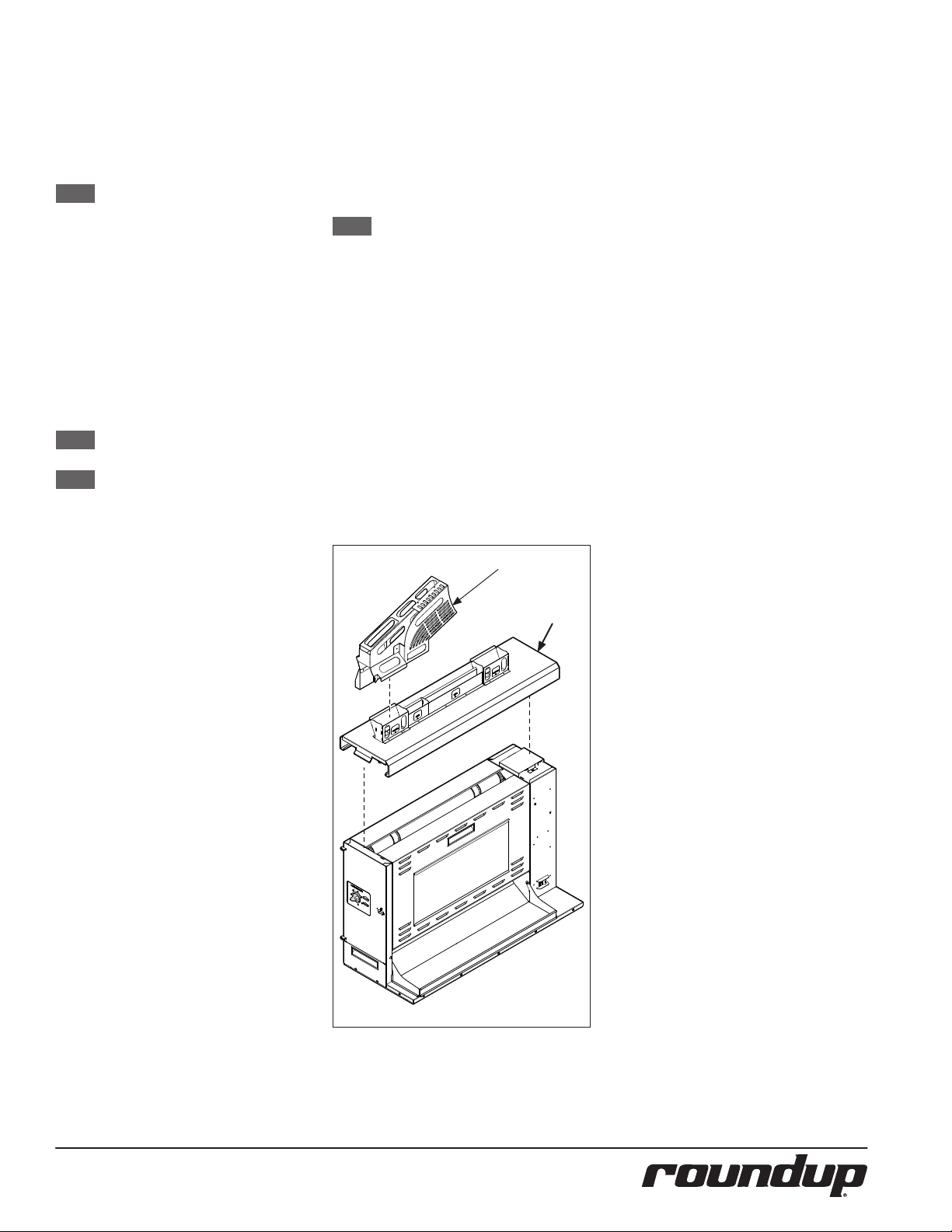
2. Put on neoprene gloves. Remove
the optional Top Feeder (if present).
Remove the Bun Feeder and Angular
Bun Feeder (Figure 5).
3. Clean the outside surfaces of the
toaster with a paper towel sprayed
with an approved multi-surface
cleaner. Allow to air dry.
4. Wipe the Top Feeder (if present)
and Bun Feeder with a paper towel
sprayed with an approved multisurface cleaner. Allow to air dry.
5. Reattach items onto the unit. Plug
the power cord into the outlet. Turn
the unit on.
OPTIONAL TOP FEEDER
PURCHASE SEPARATELY
Figure 5. Bun Feeder
BUN FEEDER
P/N 1011263 Rev. C 12/15
7
Page 8
Cleaning and Sanitizing the Belts
(Daily)
1. Turn the toaster o. The toaster
enters a cool-down mode and
automatically shuts down when
complete.
NOTE: You do NOT need to wait for the
cool down to complete.
2. Put on neoprene gloves. Remove
optional Top Feeder (if present) and
remove the Bun Feeder.
3. Clean the exterior of the toaster
with a paper towel sprayed with
an approved multi-surface cleaner
solution.
4. Remove the Front Conveyor Covers
by lifting up and away from the unit
(Figure 9 next page).
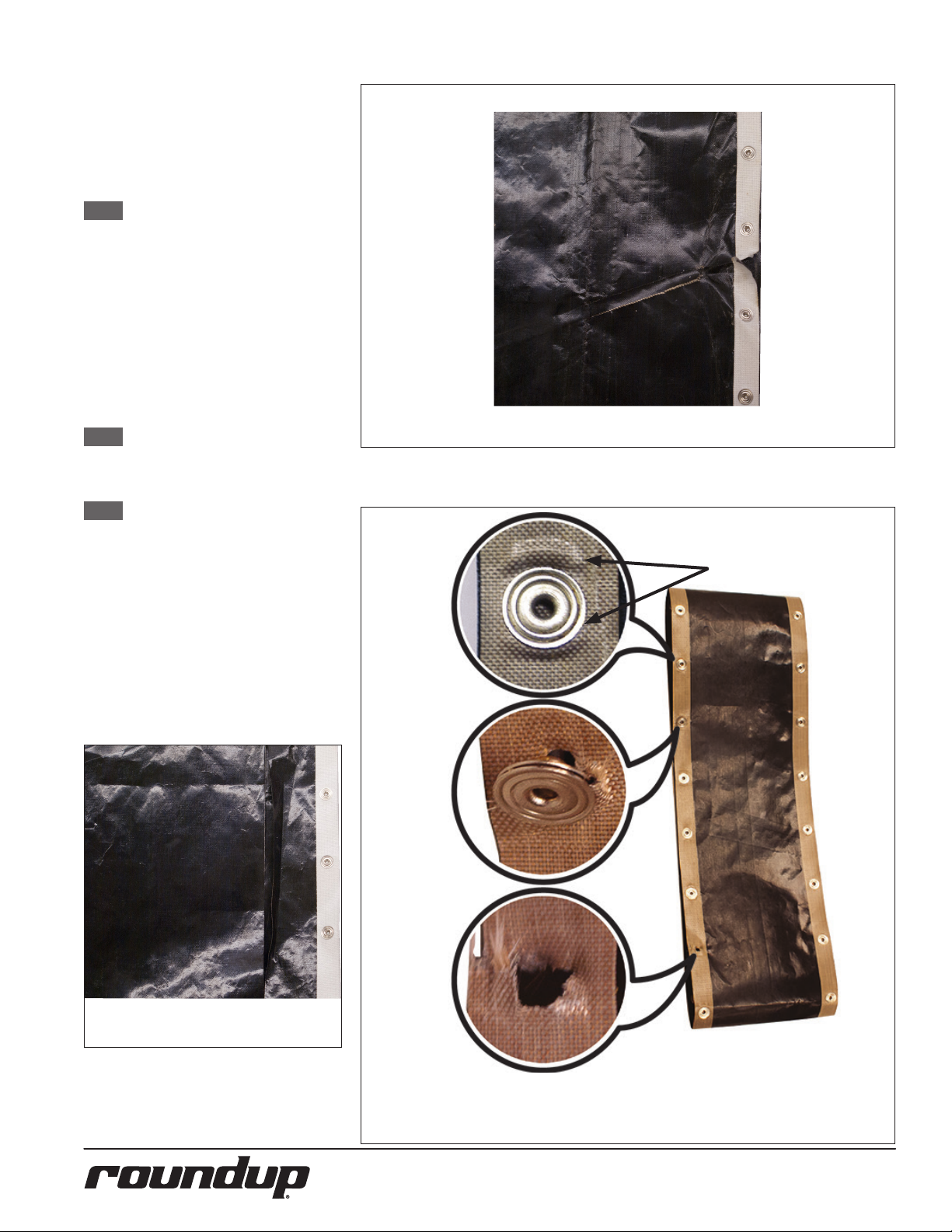
NOTE: Replace all Belts if any of the
Belts are discolored, torn, or if
any of the Belt snaps are damaged.
NOTE: Only clean the Belt when it is in
front of the Backing Plate. This
avoids causing damage to the
belt. The conveyors continue
to turn during the cool-down
period, allowing you to clean the
entire Belt.
5. Inspect the front Belt and rear Belts.
Refer to Figures 6, 7, and 8. Replace
all of the Belts if any of them are torn,
folded, discolored, missing snaps, or
damaged in any way.
Continued on page 10.
Belt is missing snaps and is damaged. Replace all Belts.
WRINKLING
AROUND SNAP
Belt is torn and folded. Replace all Belts.
BELT IS WRINKLING/DISTRESSED AROUND SNAPS, Has LOOSE/DAMAGED SNAPS,AND
IS MISSING SNAPS. REPLACE DEFECTIVE BELT
8
P/N 1011263 Rev. C 12/15
Page 9
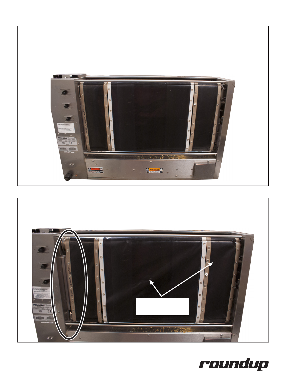
CORRECT BELT INSTALLATION
The belts are aligned vertically on the top and bottom rollers. The rollers are not visible when the belts are correctly positioned
because the snaps are properly positioned.
INCORRECT BELT INSTALLATION.
The rollers are visible in the circled section. The belts are not aligned properly. misaligned belts shift o the rollers to the left
or right. In this image, the belts are shifted to the right and the snaps are not correctly positioned on the rollers. The belts are
stretching which may result in torn belts or broken snaps.
Belts are stretching due to
incorrect installation
P/N 1011263 Rev. C 12/15
9
Page 10

6. If the Belts are all in good condition,
REAR
BACKING
PLATE
spray a clean, sanitized towel with an
approved sanitizer. Wipe the Front
Belt clean.
7. Wipe the Front Belt with a clean,
sanitized towel sprayed with an approved sanitizer. Allow to air dry.
8. Clean the Rear Belts using the same
procedure in Step 6.
NOTE: Only clean the Belt where it is in
front of the Backing Plate. This
avoids causing damage to the
belt (Figure 10).
9. Place all towels used to clean the
toaster and belts into the soiled
towel bucket.
10. Clean the Front and Rear Conveyor
Covers with a paper towel sprayed
with an approved multi-surface
cleaner. Allow to air dry.
11. Re-install the Front and Rear Conveyor Covers and then re-install the
Bun Feeder. Re-install the optional
Top Feeder (if present)
12. Turn the toaster on and test the unit
before returning it to service.
NOTE: For heavy carbon buildup, Steps
6 - 8 may need to be repeated
several times to achieve desired
cleanliness.
NOTE: Be sure to clean and sanitize the
Belts completely. Failure to properly clean the Belts will shorten
the life of the Belts and result in
poor toaster performance.
NOTE: Replace the Belts if they show ex-
cessive wear and tear. To obtain
new Belts, contact the factory at
1-877-392-7854 (North America
only) or 630-784-1000.
NOTE: Belts should be removed ONLY
during Belt replacement or when
required in a service situation.
NOTE: All Belt Wraps must be replaced
every 90 days.
Figure 9. Front and Rear Conveyor Covers
FRONT BACKING PLATE
Figure 10. Front Belt Backing Plate Location
10
P/N 1011263 Rev. C 12/15
Page 11

Replacing Belts (Quarterly)
Over time, the Belts will begin to show signs
of wear (tearing or discoloration of the belt)
at which point the belts should be replaced.
NOTE: Belts should be removed ONLY
during Belt Replacement or when
required in a service situation.
For proper operation, replace all
belts at the same time.
NOTE: All Belts MUST be replaced every
90 days.
Removing Belts
1. Turn the toaster’s power switch to
the o position. The toaster enters a
cool-down mode and will automatically shut down when complete.
2. Unplug the power cord once the
cool-down period is complete.
3. Put on neoprene gloves. Remove the
optional Top Feeder (if present) and
remove the Bun Feeder.
4. Remove the Front and Rear Conveyor Covers by lifting up and away
from the toaster.
5. Set the Compression Knob to 7.
Unlock the latch and open the left
side panel.
6. To lock the front Conveyor Roller,
face the front of the toaster. Use both
hands and push down on the Front
Conveyor Roller and pull towards
you. This removes tension and locks
the roller in place (Figure 11).
7. To lock the Rear Roller, face the rear
of the toaster. Use both hands and
push down on the Rear Conveyor
Roller and pull towards you. This
removes tension and locks the roller
in place (Figure 11).
8. Lift the upper Belt Frame Lock. Then
rotate down so it rests on the cam
shaft of the rear conveyor roller.
(Figure 12).
9. Pull down the lower Belt Frame Lock
(Figure 12).
10. Remove and discard the Front Belt
(the recommendation is to cut it in
half so it cannot be used again). See
Figure 13.
11. Remove and discard the Rear Belts
(the recommendation is to cut them
in half so they cannot be used again).
See Figure 13.
12. Wipe all four rollers with a clean towel sprayed with sanitizer. Make sure
to remove all debris from the rollers
so they are as clean as possible.
P/N 1011263 Rev. C 12/15
TENSE
LOOSE
UPPER BELT FRAME
LOCK
LOWER BELT FRAME
LOCK
CLUB/HEEL
BELT WRAP
CROWN
BELT WRAP
Figure 13. Remove and Discard the Belts
11
Figure 11. Conveyor Rollers
Figure 12. Conveyor Locks
CROWN BELT
WRAP
DO NOT REUSE THE BELTS!
TENSE
LOOSE
MAIN
BELT WRAP
Page 12

Installing Belts
1. Follow the steps for Removing Belts.
2. Wipe both sides of the new Belts
with a clean, sanitized towel sprayed
with an approved sanitizer and allow
to air dry.
3. Wipe all four rollers and the backing
plate with a clean towel sprayed with
sanitizer. Make sure to remove all
debris from the rollers and backing
plate so they are as clean as possible.
4. Slide the new front belt gently over
the front top roller and front bottom
roller.
NOTE: Make sure the belt lines up prop-
erly on the rollers. The snaps on
the belts should face the inside of
the top front roller.
5. Slide the rst crown belt over the
rear top roller and rear bottom roller.
Repeat this step for the club/ heel
belt and the second crown belt.
NOTE: Make sure the belt lines up prop-
erly on the rollers. The snaps on
the belts should face the inside of
the top rear roller.
6. Return the Front and Rear Belt Roll-
ers to full tension by lifting them up
so each roller locks into place (Figure
14).
7. Slowly lift up the Lower Belt Frame
Lock so the Front and Rear Belt
Rollers lock into place (Figure 15).
If necessary, lift up the cam shaft of
the Rear Belt Roller while lifting the
Lower Belt Frame Lock into place.
8. Re-engage the Upper Belt Frame
Lock by lifting up and then locking
it in place on the Front Conveyor Assembly (Figure 15).
9. Close and latch the Side Panel.
NOTE: Inform the Store Manager after
any Belt Replacement so new
Belts can be ordered. To obtain
new Belts, contact the factory at
1-877-392-7854 (North America
only) or 630-784-1000.
10. Set the Compression Knob to 4.
11. Re-install the Front and Rear
Conveyor Covers and then the Bun
Feeder. Re-install the optional Top
Cover assembly (if present).
12. Plug in the toaster and test the unit
before returning to service.
TENSE
LOOSE
UPPER BELT FRAME
LOCK
LOWER BELT FRAME
LOCK
TENSE
LOOSE
Figure 13. Conveyor Rollers
Figure 14. Conveyor Locks
12
P/N 1011263 Rev. C 12/15
Page 13

Cleaning the Top Cooling Fan and
Electrical Housing (Annually)
Follow these steps to clean the top fan.
1. Turn the power switch to the OFF
position. The toaster enters a cooldown mode and will automatically
shut down when complete. Unplug
the power cord.
2. Remove the optional Top Feeder (if
Present). Remove the Bun Feeder.
3. Facing the front of the toaster, move
to the right Side Panel. Remove the
2 top screws from the right Side side
Panel and lower the panel (Figure
16).
4. Use a plastic brush or similar tool to
brush all 5 fan blades from beneath.
Be sure to remove all debris.
5. Carefully clean any debris from the
inside oor of the control compartment and from all electrical connections. Be sure to remove any grease,
lint, or debris from these areas.
6. Attach the right Side Panel and
secure with screws.
7. Resasemble the unit.
Figure 16. Accessing Top Cooling Fan
Cleaning the Rear Cooling Fan
and Electrical Housing (Annually)
Follow these steps to clean the rear fan.
1. With the unit o, remove the 3 rear
screws securing the rear access panel
and carefully lower the panel (Figure
17).
2. Use a plastic brush or similar tool to
brush all 5 fan blades free of debris.
3. Carefully clean any debris from the
oor of the toaster and from all electrical connections. Be sure to remove
any grease, lint, or debris from these
areas.
4. Attach the rear panel and secure
with the 3 screws.
NOTE: Be careful not to pinch wiring
upon closing the rear panel.
5. Plug in the power cord, turn the
power switch on, and test the toaster
for proper operation.
Figure 17. Accessing Rear Cooling Fan
P/N 1011263 Rev. C 12/15
13
Page 14

TROUBLESHOOTING
WARNING
To avoid possible personal injury and/or damage to the unit, inspection, test and repair of electrical equipment should be performed
by qualied service personnel. The unit should be unplugged when servicing, except when electrical tests are required. If the trouble-
shooting steps listed do not solve your machine problem, contact an Authorized Service Agency for further assistance or service.
NOTE: The table below describes troubleshooting related to the unit display.
Problem Possible Cause Corrective Action
Unit displays error message: “SSR ‘A’ Fail.
Toaster Shut Down”. Followed by a
cool down cycle. Power, Motor, ‘B’, and ‘C’
lights are solid and Service and ‘A’ lights
are ashing.
Unit displays error message: “SSR ‘B’ Fail.
Toaster Shut Down”. Followed by a cool
down cycle. Power, Motor, ‘A’, and ‘C’ lights
are solid and Service and ‘B’ lights are
ashing.
Unit displays error message: “SSR ‘C’ Fail.
Toaster Shut Down”. Followed by a cool
down cycle. Power, Motor, ‘A’, and ‘B’ lights
are solid and Service and ‘C’ lights are
ashing.
Unit displays error message: “High Limit
Tripped. Toaster Shut Down”. Followed
by a cool down cycle.
SSR is stuck closed causing platen ‘A’ temperature to
exceed 343°C (650°F).
Failed Display Board.
Failed I/O Board.
SSR is stuck closed causing platen ‘B’ temperature to
exceed 343°C (650°F).
Failed Display Board.
Failed I/O Board.
SSR is stuck closed causing platen ‘C’ temperature to
exceed 343°C (650°F).
Failed Display Board.
Failed I/O Board.
Failed Platen Thermocouple causing the High Limit to
trip.
Defective High Limit
Cycle power o and on if fault message persist; contact your Maintenance person or Authorized Service
Agency for service.
Cycle power o and on if fault message persist; contact your Maintenance person or Authorized Service
Agency for service.
Cycle power o and on if fault message persist; contact your Maintenance person or Authorized Service
Agency for service.
Allow unit to cool and reset the High Limit. If the
High Limit trips again, contact your Maintenance
person or Authorized Service Agency for service.
Unit displays error message: “Conveyor
Stopped. Toaster Shut Down”. Followed
by a cool down cycle. Power, ‘A’, ‘B’, and
‘C’ lights are solid and Service and Motor
lights are ashing.
Unit displays error message: “Internal
Error. Power Plug: Out/In”.
Unit displays error message: “Control
Temperature Fail. Toaster Shut Down”.
Followed by a cool down cycle. The control compartment’s ambient temperature
is above 60°C (140°C).
Problem Possible Cause Corrective Action
Unit displays fault message: “’A’ System
Fail”. Followed by a graphic display.
Power, Motor, ‘B’, and ‘C’ lights are solid
and Service and ‘A’ lights are ashing.
Mechanical bind in one of the conveyors. Cycle power o and on if fault message persist; con-
Defective Motor
Damaged Ball Bearing(s).
Drive chain or sprockets are damaged.
Failed Display Board.
Failed I/O Board.
Internal board error. Turn unit o and unplug . Plug unit back in, Turn unit
Cooling Fan(s) are dirty and need to be cleaned. Verify vents on toaster are unblocked and not near
Failed Cooling Fan(s).
Failed Display Board.
Failed I/O Board.
SSR is stuck open causing platen ‘A’ to not reach set
point within 30 minutes.
Failed Platen ‘A’ Heater.
Failed Display Board
Failed I/O Board.
Loose wire or connection.
Failed thermocouple.
tact your Maintenance person or Authorized Service
Agency for service.
on and if error persists; contact your Maintenance
person or Authorized Service Agency for service.
other heating appliances. Clean fans describe in the
Maintenance section of this manual. If error persists
contact your maintenance person or Authorized
Service Agency for service.
Cycle power o and on if fault message persist; contact your Maintenance person or Authorized Service
Agency for service.
14
P/N 1011263 Rev. C 12/15
Page 15

Problem Possible Cause Corrective Action
Unit displays fault message: “’B’ System
Fail”. Followed by a graphic display.
Power, Motor, ‘A’, and ‘C’ lights are solid
and Service and ‘B’ lights are ashing.
Unit displays fault message: “’C’ System
Fail”. Followed by a graphic display.
Power, Motor, ‘A’, and ‘B’ lights are solid
and Service and ‘C’ lights are ashing.
Unit displays fault message: “’A’ Platen
Low”. Followed by a graphic display.
Power, Motor, ‘B’, and ‘C’ lights are solid
and Service and ‘A’ lights are ashing.
Unit displays fault message: “’B’ Platen
Low”. Followed by a graphic display.
Power, Motor, ‘A’, and ‘C’ lights are solid
and Service and ‘B’ lights are ashing.
Problem Possible Cause Corrective Action
Unit displays fault message: “’C’ Platen
Low”. Followed by a graphic display.
Power, Motor, ‘A’, and ‘B’ lights are solid
and Service and ‘C’ lights are ashing.
Unit displays fault message: “’A’ Sensor
Open”. Followed by a graphic display.
Power, Motor, ‘B’, and ‘C’ lights are solid
and Service and ‘A’ lights are ashing.
Unit displays fault message: “’B’ Sensor
O p e n ”. Followed by a graphic display.
Power, Motor, ‘A’, and ‘C’ lights are solid
and Service and ‘B’ lights are ashing.
Unit displays fault message: “’C’ Sensor
Open”. Followed by a graphic display.
Power, Motor, ‘A’, and ‘B’ lights are solid
and Service and ‘C’ lights are ashing.
SSR is stuck open causing platen ‘B’ to not reach set
point within 30 minutes.
Failed Platen ‘B’ Heater.
Failed Display Board
Failed I/O Board.
Loose wire or connection.
Failed thermocouple.
SSR is stuck open causing platen ‘C’ to not reach set
point within 30 minutes.
Failed Platen ‘C’ Heater.
Failed Display Board
Failed I/O Board.
Failed thermocouple.
Loose wire or connection.
SSR is stuck open causing platen ‘A’ temperature to
decrease by 27° C (50° F) after achieving set point.
Failed Platen ‘A’ Heater.
Failed Display Board
Failed I/O Board.
Loose wire or connection.
Failed thermocouple.
SSR is stuck open causing platen ‘B’ temperature to
decrease by 27° C (50° F) after achieving set point.
Failed Platen ‘B’ Heater.
Failed Display Board
Failed I/O Board.
Loose wire or connection.
Failed thermocouple.
SSR is stuck open causing platen ‘C’ temperature to
decrease by 27° C (50° F) after achieving set point.
Failed Platen ‘C’ Heater.
Failed Display Board
Failed I/O Board.
Failed thermocouple.
Loose wire or connection.
Disconnected/Failed Platen ‘A’ Thermocouple. Cycle power o and on if fault message persist; con-
Failed Display Board.
Disconnected/Failed Platen ‘B’ Thermocouple. Cycle power o and on if fault message persist; con-
Failed Display Board.
Disconnected/Failed Platen ‘C’ Thermocouple. Cycle power o and on if fault message persist; con-
Failed Display Board.
Cycle power o and on if fault message persist; contact your Maintenance person or Authorized Service
Agency for service.
Cycle power o and on if fault message persist; contact your Maintenance person or Authorized Service
Agency for service.
Cycle power o and on if fault message persist; contact your Maintenance person or Authorized Service
Agency for service.
Cycle power o and on if fault message persist; contact your Maintenance person or Authorized Service
Agency for service.
Cycle power o and on if fault message persist; contact your Maintenance person or Authorized Service
Agency for service.
tact your Maintenance person or Authorized Service
Agency for service.
tact your Maintenance person or Authorized Service
Agency for service.
tact your Maintenance person or Authorized Service
Agency for service.
P/N 1011263 Rev. C 12/15
15
Page 16

Problem Possible Cause Corrective Action
Unit displays fault message: “Motor
Running Slow. See Operators Manual”.
Power, ‘A’, ‘B’, and ‘C’ lights are solid and
Service and ‘Motor’ lights are ashing.
Unit displays: “Display BD U2”, “Display
BD U4”, Display BD U6”, Display BD U7”,
“I/O BD U1”, “I/O BD U2”, “I/O BD U10”,
“Calibration Fault”.
Mechanical bind in one of the conveyors. Cycle power o and on if fault message persist; con-
Damaged Ball Bearing(s).
Drive chain or sprockets are damaged.
Defective Motor
Failed Display Board
Failed I/O Board.
Internal board error. Turn unit o and unplug. Plug unit back in. turn unit
tact your Maintenance person or Authorized Service
Agency for service.
back on if error persists; contact your Maintenance
person or Authorized Service Agency for service.
16
P/N 1011263 Rev. C 12/15
Page 17

NOTE: The table below describes non-error/fault troubleshooting.
Problem Possible Cause Corrective Action
Buns not toasting adequately Compression settings are
Buns must be forced into the
toaster. Buns Sticking and
burning.
Toaster makes unusual
sounds.
Compression side door will
not close.
Fan(s) are making an unusual
sound.
incorrect.
Temperature Settings are
incorrect
Motor setting are incorrect. Verify that the motor setting is set to 4100 for compression setting 4 or 4000 for com-
Belts are worn or need cleaning
(replace quarterly).
One of the conveyor’s top
shafts is stuck in lower lock
position.
Either or both Upper/Lower
Conveyor Locks are not properly locked in place.
Buns do not meet specications.
Belts are worn or need cleaning
(replace quarterly).
Chain and/or sprockets are
worn and/or loose.
Compression setting is incorrect.
Buns are not inserted into the
toaster properly.
Compression setting is incorrect.
Belts are installed incorrectly. Belts must be installed as described in the Maintenance section of this manual.
Belts are worn or need cleaning
(replace quarterly).
Motor Drive chain needs
lubrication.
Bearing(s)are worn and/or
binding.
Either or both Upper/Lower
Conveyor Locks are not properly locked in place.
Failed Cooling Fan(s). Verify vents on toaster are unblocked and not near other heating appliances. Clean
Cooling Fan(s) are dirty and
need to be cleaned.
Use recommended setting of 4. See the Programming section of this Manual if using a
setting of 5.
Verify that Platen ‘A’ set point is set to 271°C (520°F), Platen ‘B’ set point is set to 271°C
(520°F), and Platen ‘C’ is set point is set to 254°C (490°F). For making changes to the set
point temperature or if using a compression setting of 5, see the Programming section
of this manual.
pression setting 5 as described in the Programming section of this Manual.
Inspect belts for cleanliness, worn spots, tears, or wrinkles. Clean or replace belts as
described in the Maintenance section of this manual.
Inspect position of the shafts as described in the Maintenance section of this manual.
Inspect the proper position of the Locks as described in the Maintenance section of this
manual.
Contact your bun supplier.
Inspect belts for cleanliness, worn spots, tears, or wrinkles. Clean or replace belts as
described in the Maintenance section of this manual.
Contact your maintenance person or an Authorized Service Agency for service.
Use recommended setting of 4. See the Programming section of this Manual if using a
setting of 5.
Verify buns are being inserted into the designated area of the Bun Feeder Assembly with
the cut side of the bun facing towards the front of the unit.
Use recommended setting of 4. See the Programming section of this Manual if using a
setting of 5.
Inspect belts for cleanliness, worn spots, tears, or wrinkles. Clean or replace belts as
described in the Maintenance section of this manual.
Lubricate the Drive Chain carefully with Lubit-8 (P/N 2140152) at least once a year.
Contact your maintenance person or an Authorized Service Agency for service.
Inspect the proper position of the Locks as described in the Maintenance section of this
manual.
fans describe in the Maintenance section of this manual. If error persists contact your
maintenance person or Authorized Service Agency for service.
P/N 1011263 Rev. C 12/15
17
Page 18

REPLACEMENT PARTS
Item Part No. Description Qty.
2 0012774 Bun Feeder Assembly 1
3 0506184 Bun Stop Bracket 1
4 0021733 Club Base Divider 1
Weldment
5 7000884 Damper Replacement 1
Kit Incl. Items 6, 7, 8, & 9
6 0400425 Damper 2
7 0506300 Damper Support 2
8 0600132 Spring, Damper 2
Support
9 306P104* Screw, Mach. #06-32 x 1/4 8
* Items available in packages of ten (10)
OPTIONAL ACCESSORY
18
Top Feeder
Order Part Number 7001110
P/N 1011263 Rev. C 12/15
Page 19

23
20
21
24
22
26
25
26
17
11
9
8
7
1
2
Item Part No. Description Qty.
1 2100253 Knob, 1/4” Shaft, Push-On 1
2 1001417 Label, Compression 1
3 0506179 End Housing Panel 1
4 325P193* Screw, Hex Head, #1/4-20 X 1.375” 1
5 0506188 Bracket, Housing Locking 1
6 2120216 Spacer,Upper Locking Plate, Front 1
7 310P146* Nut, Hex ‘KEPS’ #10-32 1
(see Item 29, 30,, & 31)
8 325P176* Screw, Flange Hex Head Cap 1
(see item 30 & 31)
9 0506291 Bracket, Tensioner- 1
End Housing, Rear (See item 31)
10 0506292 B racket, Tensioner- 1
End Housing, Front (see item 30)
11 2150285 Bearing, Single Groove S/S 8
(See Item 29, 30 & 31)
1412
17
15
10
13
6
5
4
3
Item Part No. Description Qty.
12 0504320 Spacer 0.781 X 1.125 X 0.06” 10
(see Item 29, 30 & 31)
13 0600158 Spring, Roller Tension 4
(see item 30 & 31)
14 0506293 Plate, Tensioner - End Housing, Rear 1
(see item 31)
15 0506294 Plate, Tensioner - End Housing, Front 1
(See item 30)
16 0506167 Bracket, Bearing 2
17 325P194* Screw, Hex Head, 4
#1/4-20 X 2.00”, S.S.
18 0021714 Weldment, End Housing Rod Support 1
19 0400418 Push In Grommet For 1-1/8” Dia. Hole 1
20 0021725 Weldment, Bearing Bracket 1
& Spring Guide LH (see item 30)
21 0021724 Weldment, Bearing Bracket 1
& Spring Guide RH (See item 30)
27
31
12
11
12
16
7
18
19
28
Item Part No. Description Qty.
22 308P145* Nut, Hex Acorn #08-32 11
23 0600156 Spring, Cam Adjustment 2
24 0012814 Cam Bracket & Thrust Strip
Assembly, LH 1
25 2120223 Sleeve Bearing, .50” Od X .75” LG 2
26 2120213 Spacer, Frame & Platen LH 4
27 2150322 Cam 2
28 310P110* Screw, Mach. #10-32 X 1/2” 2
29 7000856 Bearing Kit (incl. items 7, 11, & 12) 1
30 7000859 Idler Shaft Tensioner Assy. Front End 1
Hsg. Side Kit (Incl. items 7, 8, 10, 11,
12, 13, 15, & 21)
7000860 Idler Shaft Tensionser Assy. Rear End 1
Hsg. Side Kit (Incl. items 7, 8, 9, 11,
12, 13, 14, & 20)
31 0600143 Spring, Compression Setting 1
* Items available in packages of ten (10)
P/N 1011263 Rev. C 12/15
19
Page 20

1
2
3
4
5
5
5
6
8
7
9
29
13
28
11
10
12
13
14
15
27
Item Part No. Description Q ty.
1 308P151* Screw, SEMS #8-32 x 5/16” 1
2 0506155 Duct, Fan 1
3 3100213 Screw, PHPNHD #10-16 x 3/4” 1
THRD Form, #3 PT
4 7000913 Fan Kit (Incl. Item 3) 1
5 4030352 Thermostat, Hi-Limit 3
6 4060387 Terminal Block, 2 Pole 1
7 306P105* Screw, Mach #6-32 x 1/4 1
8 0400375 Strain Relief, Cord 1
9 0400376 Lock-nut, Conduit 1
10 308P193* Screw, Mach #08-32 x 1 1/4 1
11 4060398 Terminal Block, S-Series 1
12 0700588 Power Cord
26
25
23
24
13
22
tem Part No. Description Q ty.
13 304P105* Nut, Hex KEPS #4-40 Zinc 1
14 7000870 I/O Board Kit 1
15 7001131 Vert Toast I/O PCB Kit 1
16 1001399 Label, Control 1
17 1001394 Label, Smart Enabled MCD 1
18 2100212 Handle, Pull, Snap-in 3
19 0506139 Control Panel 1
20 1001213 Label, Shock Hazard 1
21 1001434 Label, Thermocouple 1
22 2090163 Filter, RFI 250VAC 1
23 306P103* Screw, Mach #06 x 3/80 1
24 4050240 Relay, Solid State Dual Pole 1
With Conn-receptical
16
21
19
17
20
30
18
tem Part No. Description Qty.
25 0506156 Heat Sink, Relay 1
26 7000370 Solid State Relay Kit 1
27 7000868 Switch Kit, Power 1
28 2110199 Clip “C” type 9
29 7000871 Varistor Board Kit 1
30 1000900 Label, Service 1
* Items available in packages of ten (10)
20
P/N 1011263 Rev. C 12/15
Page 21

2
1
6
5
7
3
8
9
10
11
12
4
13
14
15
23
Item Part No. Description Qty.
1 310P124* Screw, #10-32 X 2-1/4” 1
Truss Head S/S
2 0506093 Support Bracket, LH 1
3 0506149 Cover, Adj. Platen 1
4 0021780 Crown Plate Weldment 1
End Housing Side
5 0100272 Platen, Club 1
6 0506178 Plate, Heel Platen 1
7 0506168 Plate, Crown 1
8 0021719 Weldment, Idler Roller Rear Top 1
9 0021718 Weldment, Idler Roller Front Top 1
10 0021707 Weldment, Adj. Platen Frame 1
11 2150303 Cam Shaft 1
12 0021711 Weldment, Fixed Platen Frame 1
13 0021721 Weldment, Drive Roller Rear Bottom 1
14 0021720 Weldment, Drive Roller Front Bottom 1
15 7000795 Crown Belt 1
16 7000967 Heel/Club Belt 1
17 7000796 Main Belt 1
18 0100266 Platen, Main (see Item 29) 1
19 0400416 Insulation, Main Platen (see Item 29) 1
16
17
Item Part No. Description Qty.
20 308P102* Washer, Int. Tooth #08 Steel 1
Zinc Plated (see Item 29)
21 308P164* Screw, Mach. #8-32 x 1” LG 1
(see Item 29)
22 0506092 Support Bracket, RH 1
23 7000799 Belt Kit (incl. items 15, 16 & 17) 1
24 0506150 Cover, Fixed Platen 1
25 0400290 Insulator, Electrical 4
26 0506158 Insulation Plate 1
27 308P151* Screw, SEMS #8-32 x 5/16” Flex Line 1
(see Item 29)
28 0506183 Retainer Plate, Thermocouple 1
(see Item 29)
29 7000857 Main Platen Kit 1
* Items available in packages of ten (10)
18
26
29
19
20
21
21
28
27
27
21
25
25
21
22
1
1
1
1
24
P/N 1011263 Rev. C 12/15
21
Page 22

16
16
13
16
14
16
8
14
15
15
16
13
16
13
15
16
14
8
8
13
8
16
8
15
14
8
13
16
12
13
16
14
14
13
8
16
13
8
10
12
10
11
11
9
12
7
2
3
9
6
Item Part No. Description Qty.
1 0012594 Adj. Platen Assembly 1
2 0021710 Weldment, Back Plate Adj. Platen 1
3 0021712 Weldment, Crown Plate 1
4 0021780 Crown Plate Weldment 1
End Housing Side
5 0100271 Platen, Club 230 VAC, 900W 1
(See Item 17)
6 0400290 Insulator, Electrical 1
7 0400417 Insulation, Fiberglass Club Platen 1
(See Item 17)
8 0506083 Spacer 8
9 0506178 Plate, Heel Platen 1
10 0506198 Spacer, .625 OD x .218 x .075 Thick 2
(See Item 17)
11 2120226 Spacer, .50 OD x .203 ID x .328 Thick 2
(See Item 17)
12 2120227 Spacer, .50 OD x 203” ID x .265 Thick 2
(See Item 17)
13 310P102* Washer, Lock #10 S/S Internal Tooth 1
(See Item 17)
17
5
6
4
Item Part No. Description Qty.
14 310P140* Washer, Flat #10 Stl/ZN 1
.219 x .500 x .049 (See Item 17)
15 310P209* Screw, Mach #10-24 x 3/4” 1
Slotted TrussHD 18-8SS
16 310P214* Screw, Hex #10-322 x 1/4 1
Thrd Cutting Type F, SS
7000875 Club Platen Assy. Kit 1
(Incl. Items 5, 7, 10, 11, 12, 13, & 14)
* Items available in packages of ten (10)
22
P/N 1011263 Rev. C 12/15
Page 23

1
7
9
Item Part No. Description Qty.
1 4050241 Contactor, 4 Pole 1
2 7000886 Snubber Board Kit 1
3 7000913 Fan - Axial, 200/230 VAC 1
4 300P102* Nut, Speed #8-32 “U” 1
5 4070170 MCD Vert Toaster Filter Board 1
6 304P105* Nut, Hex KEPS #4-40 Zinc 1
7 4010221 Cap-MP, Motor Run 1
8 4050242 Filter, Power Line, 10A 2
120/250 V, 50-60 HZ
9 308P143 Nut, Hex KEPS #08-32 1
11 0506181 Elec. Panel 1
12 308P124* Screw, Mach #8-32 x 1/2” 1
13 308P157* Screw, Tap #08-32 x 3/8 1
14 310P103* Screw, Mach #10-32 x 1/4 1
15 0506170 Fan Cover 1
* Items available in packages of ten (10)
6
2
5
8
8
12
4
3
14
13
15
P/N 1011263 Rev. C 12/15
23
Page 24

WIRING DIAGRAM
24
P/N 1011263 Rev. C 12/15
Page 25

NOTES
P/N 1011263 Rev. C 12/15
25
Page 26

NOTES
26
P/N 1011263 Rev. C 12/15
Page 27

NOTES
P/N 1011263 Rev. C 12/15
27
Page 28

 Loading...