

Page 1
Wendy’s
GST-2V Vertical Toaster
Manufacturing Numbers:
9210980
www.antunes.com
P/N 1011443 Rev. A 05/17
Page 2
TABLE OF CONTENTS
Table of Contents 2
Warranty
Information 2
Service/Technical
Assistance 2
Important Safety
Information 3
Warnings 3
Specications 4
Installation 5
Operation 5
Light/Dark Adjustments 5
User Mode 6
Manager Mode 6
Safety Features 6
Hi-Limit Control 6
Purging buns from Toaster 6
Fault Messages 6
Error Codes 6
Daily Cleaning 7
Clean the Toaster and Belt Wraps 7
Quarterly Cleaning 9
Remove Belt Wraps and
Clean Rollers 9
Install Belt Wraps 9
Clean Cooling Fan and
Electrical Housing 10
Troubleshooting 11
Wiring Diagram 12
Replacement PArts 13
Limited Warranty 16
WARRANTY
INFORMATION
Please read the full text of the Limited
Warranty in this manual.
If the unit arrives damaged, contact
the carrier immediately and le a damage claim with them. Save all packing
materials when ling a claim. Freight
damage claims are the responsibility of
the purchaser and are not covered under
warranty.
The warranty does not extend to:
y Damages caused in shipment or
damage as result of improper use.
y Installation of electrical service.
y Normal maintenance as out-
lined in this manual.
y Malfunction resulting from
improper maintenance.
y Damage caused by abuse
or careless handling.
y Damage from moisture into
electrical components.
y Damage from tampering with,
removal of, or changing any
preset control or safety device.
SERVICE/TECHNICAL
ASSISTANCE
If you experience any problems with the
installation or operation of your unit,
contact Antunes Technical Service at +1877-392-7854.
Fill in the information below and have it
handy when calling for assistance. The
serial number is on the specication plate
located on Use only genuine Antunes
replacement parts in this unit. Use of
replacement parts other than those supplied by the manufacturer will void the
warranty.
Purchased From
Date of Purchase
Model Number
Serial Number
Manufacturing Number
IMPORTANT
A.J. Antunes & Co. reserves the right to
change specifications and product de-
sign without notice. Such revisions do
not entitle the buyer to corresponding
changes, improvements, additions or
replacements for previously purchased
equipment.
IMPORTANT
Keep these instructions for future refer-
ence. If the unit changes ownership,
be sure this manual accompanies the
equipment.
2
P/N 1011443 Rev. A 05/17
Page 3

IMPORTANT SAFETY
INFORMATION
Use the following guidelines for safe operation of the unit.
y Read all instructions be-
fore using equipment.
y For your safety, the equipment is
furnished with a properly grounded
cord connector. Do not attempt to
defeat the grounded connector.
y Install or locate the equipment only
for its intended use as described in
this manual. Do not use corrosive
chemicals in this equipment.
y Do not operate this equipment if
it has a damaged cord or plug, if
it is not working properly, or if it
has been damaged or dropped.
y This equipment should be serviced
by qualied personnel only. Contact
your nearest Authorized Service
Agency for adjustment or repair.
y Do not block or cover any
openings on the unit.
y Do not immerse cord
or plug in water.
y Keep cord away from
heated surfaces.
y Do not allow cord to hang over
edge of table or counter.
y Turn the power o, unplug the
power cord, and allow unit to
cool down before performing any
service or maintenance on the unit.
NOTE: Turning o the power switch
does NOT turn o all power to
the unit.
y The procedures in this manual may
include the use of chemical products. These chemical products will
be highlighted with bold face letters
followed by the abbreviated HCS
(Hazard Communication Standard).
See Hazard Communication Standard manual for the appropriated
Material Safety Data Sheets (MSDS).
y The equipment should be grounded
according to local electrical codes to
prevent the possibility of electrical shock. It requires a grounded
receptacle with separate electrical
lines, protected by fuses or circuit
breaker of the proper rating.
y All electrical connections must
be in accordance with local electrical codes and any
other applicable codes.
y Do not clean this appli-
ance with a water jet.
WARNINGS
Be advised of the following warnings
when operating and performing maintenance on this unit.
y If the supply cord is damaged, it
must be replaced by the manufacturer or its service agent or
a similarly qualied person
in order to avoid a hazard.
y Do not modify the power sup-
ply cord plug. If it does not t
the outlet, have a proper outlet
installed by a qualied electrician.
y Do not use an extension
cord with this appliance.
y Electrical ground is re-
quired on this appliance.
y Check with a qualied electrician if
you are in doubt as to whether the
appliance is properly grounded.
y When using a chemical cleaner,
be sure it is safe to use on cast
aluminum. Observe all precautions
and warnings on product label.
y Inspection, testing, and repair
of electrical equipment should
only be performed by qualied service personnel.
y Do not use a sanitizing solution or
abrasive materials. These may cause
damage to the stainless steel nish.
y Chlorides or phosphates in clean-
ing agents (e.g. bleach, sanitizers,
degreasers or detergents) could
cause permanent damage to
stainless steel equipment. The
damage is usually in the form of
discoloration, dulling of metal
surface nish, pits, voids, holes, or
cracks. This damage is permanent
and not covered by warranty.
y The following tips will help
in the maintenance of stainless steel equipment:
• Always use soft, damp cloth for
cleaning, rinse with clear water
and wipe dry. When required,
always rub in direction of metal
polish lines.
• Routine cleaning should be
done daily with soap, ammonia
detergent, and water.
• Stains and spots should be
sponged using a vinegar solution.
• Finger marks and smears should
be rubbed o using soap and
water.
• Hard water spots should be removed using a vinegar solution.
P/N 1011443 Rev. A 05/17
3
Page 4
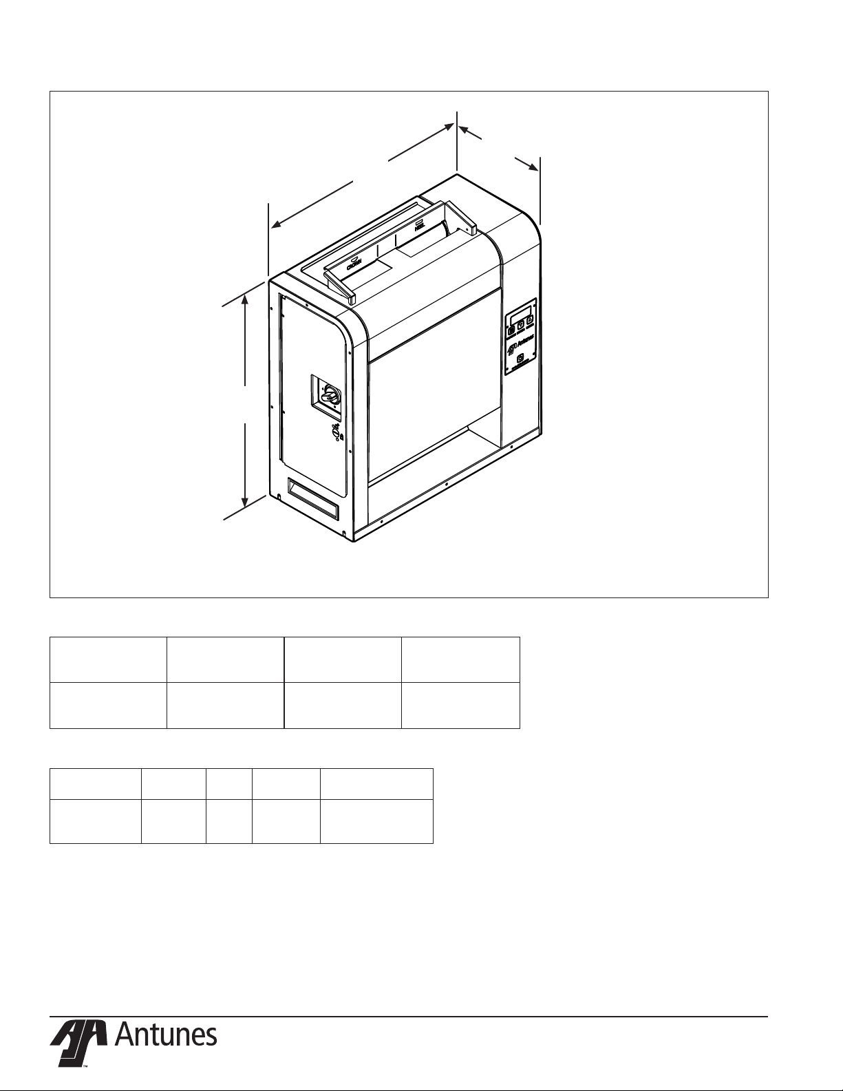
SPECIFICATIONS
B
A
C
Model &
Mfg. No.
GST-2V
9210980
Model &
Mfg. No.
GST-2V
9210980
Width
(A)
20”
(508 mm)
Volts Watts Hertz
208 2000 60
Depth
(B)
9 “
(227 mm)
Plug
Description
NEMA 6-20P
20 Amp, 250 Volt
Right Angle
Height
(C)
21 5/8”
(549 mm)
4
P/N 1011443 Rev. A 05/17
Page 5
INSTALLATION
1. Remove unit and all packing mate-
rials from shipping carton.
NOTE: If any parts are missing or dam-
aged, contact Antunes Customer Service IMMEDIATELY at
+1-877-392-7856 (toll free).
2. Remove all packing materials and
protective coverings from the unit.
3. Wipe the entire exterior of the
toaster and the accessories mentioned above with a hot damp
cloth. Allow to air dry
NOTE: Do NOT use a dripping wet
cloth. Wring out before use.
4. Attach the top cover and bun
feeder (Figure 3).
5. Set the Compression Knobs to
the desired setting (Figure 1). The
recommended Compression Settings are:
CROWN - #4
HEEL - #3
6. Plug the power cord into the ap-
propriate power outlet. Refer to the
specication plate for the proper
voltage.
When placing the toaster into service, pay attention to the following
guidelines.
• Make sure the power switch
is o and the unit is at room
temperature before plugging in
the power cord.
• Do not block or cover any openings on the unit.
• Do not immerse the power cord
or plug in water.
• Keep the power cord away from
heated surfaces.
• Do not allow the power cord
to hang over edge of table or
counter.
• Place the unit on a sturdy, level
table or other work surface.
• Turn the power switch to o (if it
is set to on).
• Ensure the line voltage corresponds to the stated voltage
on the specication label and
power cord warning tag.
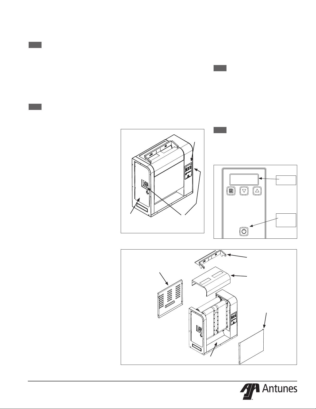
OPERATION
1. Press and release the Power button
to turn the toaster on. Allow the
toaster to warm up until USE appears in the display. See Figure 2.
2. Set the Compression Knobs to the
desired setting. The recommended
Compression Settings are:
CROWN - #4
HEEL - #3
3. Insert product into the appropriate
lane on the Bun Feeder according
to Bun Feeder labels. Insert buns
with the cut side towards the inside
of the toaster.
4. Finished product drops onto the
heated bun landing zone.
CONTROL
PANEL
SIDE DOOR
Figure 1. GST-2V Toaster
CONVEYOR
COMPRESSION KNOB
BOTH SIDES OF TOASTER
REAR
COVER
Light/Dark Adjustments
The light/dark value (Figure 2) can be
adjusted when the unit is displaying USE.
To adjust the light/dark value:
1. Press the LIGHTER or DARKER button. The display changes to show
the current light/dark value.
NOTE: The default setting is d0.
2. Press the LIGHTER or DARKER
buttons to change the light/dark
value. The adjustment range is L1L9 and d0-d9. L9 is the lightest, d0
is the middle, and d9 is the darkest
setting.
3. To save the light/dark value, wait 5
seconds until USE appears in the
display.
NOTE: Adjusting the light/dark value
changes the speed of the conveyors - it does NOT change the
temperature. The light/dark
value resets to the default value
of d0 when the unit is turned o.
LIGHTER
PROGRAM
DARKER
Figure 2. - GST-2V Control Panel
BUN FEEDER
TOP COVER
FRONT
CONVEYOR
COVER
UNIT
DISPLAY
POWER
BUTTON
ON/OFF
P/N 1011443 Rev. A 05/17
HEATED BUN LANDING ZONE
Figure 3. Components
5
Page 6

USER MODE
User Mode allows an operator to view the
toaster settings but does not permit any
adjustments. User Mode is accessed via the
Control Panel (Figure 4).
1. Press and hold the PROGRAM button for 5 seconds. After 5 seconds,
the unit displays the actual temperature of the Platen.
2. Press the LIGHTER button to toggle
between the Setpoint and actual
temperature of the Platen heater.
3. Press the PROGRAM button to
proceed to the Motor Menu. The
display shows pass through time in
seconds.
4. Press the LIGHTER button to toggle
between the Setpoint and actual
speed of the Motor.
NOTE: The unit exits User Mode after 5
seconds of keypad inactivity.
MANAGER MODE
Manager Mode, accessed via the Control
Panel (Figure 4), allows an operator to view
and adjust the following settings:
y Heater Temperature
y Pass Through Time
y Temperature Units
(Celsius or Fahrenheit)
Manager Mode also allows an operator to
view (but not adjust) the Ambient Temperature of the Control Compartment.
1. Press and release the Power button
to turn the toaster o.
2. Press and release the Power button
while holding the PROGRAM button. Continue holdin g the button
until “ENA” appears on the display
(after approximately 10 seconds).
3. Release the PROGRAM button. The
display shows the Heater Setpoint
Temperature.
4. To adjust the Heater Setpoint
Temperature, press the LIGHTER
or DARKER buttons to reach the
desired temperature.
NOTE: The recommended temperature
setting for the Platen is 535 °F
(279 °C).
5. Press the PROGRAM button to pro-
cedure to the Pass Through Time.
6. Adjust the Motor Speed Setpoint by
pressing the LIGHTER or DARKER
buttons change the pass through
time in 0.5 second increments.
NOTE: The Motor Speed is adjustable
from 1-100. The recommended
setting is 17.0 seconds.
7. Press the PROGRAM button to pro-
ceed to the Temperature Units.
8. To change the Temperatures units
from Fahrenheit or Celsius, press
the LIGHTER or DARKER buttons.
9. Press and hold the PROGRAM button to save any changes.
NOTE: The unit exits Manager Mode
after 30 seconds of keypad inactivity.
SAFETY FEATURES
Hi-Limit Control
A Hi-Limit Control turns o electrical power
to the heaters and control circuits and
displays HL if the unit overheats. To reset
the control:
1. Let the unit cool for 15 minutes.
2. Locate the Hi-Limit Controls on the
rear of the unit. Remove the black
protective cap.
3. Press and release the button. Reinstall the protective cap.
NOTE: If the Hi-Limit Control requires
continuous resetting, contact
your Authorized Service Agency.
Purging buns from Toaster
If buns get stuck in the toaster, press and
hold both the UP and DOWN arrow buttons to increase the belt speed until the
buns are purged from the toaster.
LIGHTER
PROGRAM
service +1 (877) 392-7854
DARKER
UNIT
DISPLAY
POWER
BUTTON
ON/OFF
Fault Messages
The unit displays fault messages when
there is a problem with the unit.
y “Hi” ashes if the Platen Heater
temperature is 30 °F more than the
Setpoint or if the Platen Thermocouple is disconnected or open.
y “CHEC” ashes when the control
compartment ambient temperature is more than 150 °F (66
°C). All heaters shut o. The unit
will not restart until the control
compartment ambient temperature falls below 140 °F (60 °C).
y “PO” ashes if the incoming
power drops below 190 volts.
The toaster shuts down.
y “StoP” ashes when the mo-
tor has stopped for seven
continuous seconds.
y “SpEd” ashes when the motor
speed drops 25% below the Setpoint for 30 continuous seconds.
y “HL” The Hi-Limit has tripped
and needs to be reset.
Error Codes
If any of the following Error Codes appear,
press and release the Power button to turn
the toaster o. Allow the unit to cool. Then
press and release the Power button to turn
the toaster on. If the error repeats, contact
Antunes Technical Service for assistance.
NOTE: ERR #1, 2 , 3, 5, 6, 7, and 30 to
51: Internal Error. Cycle the
power. If error persists, replace
the board.
Error Description
ERR 8 Motor running when it should be
o.
ERR 10 High Internal Temperature.
ERR 11 Shorted Thermocouple.
ERR 12 Open Thermocouple.
ERR 13 Slow warm up.
ERR 14 Shorted Solid State Relay (SSR).
Figure 4. - GST-2V Control Panel
6
P/N 1011443 Rev. A 05/17
Page 7

DAILY CLEANING
Clean the Toaster and Belt Wraps
1. Press the Power button to turn
the unit o. The unit enters a cool
down mode and the belts continue
to turn. The toaster automatically
shuts down when complete.
NOTE: You do not need to wait for the
unit to shut down to perform
these steps.
2. Wearing Heat-resistant gloves, Re-
move the bun feeder, top cover, and
the front and rear conveyor covers
(Figure 5).
3. See Figures 6 - 9. Inspect the front
belt for any tears, discoloration, or
damage to the Belt Wrap snaps.
Replace any damaged Belt Wrap as
needed. With proper maintenance
the Crown and Main Belt Wraps can
six months or longer.
4. If the front belt is in good condition, spray a clean, sanitizer-soaked
towel Sink Detergent solution. Wipe
the front belt clean. Rinse the front
belt with a separate clean, sanitizersoaked towel. Allow to air dry.
NOTE: The belt rollers continue turning
while in cool-down mode. This
allows you to clean the entire
belt. Only clean the belt where
it is in front of the Backing Plate
- between the support rods - to
avoid causing damage to the
belt. Repeat this step several
times if there is heavy carbon
buildup on the conveyor belt.
5. See Figures 6 - 9. Inspect the rear
belts for any tears, discoloration,
or damage to the Belt Wrap snaps.
Replace any damaged Belt Wrap as
needed. With proper maintenance
the Crown and Main Belt Wraps can
six months or longer.
6. If the rear belt is in good condition, spray a clean, sanitizer-soaked
towel with Sink Detergent solution.
Wipe the rear belt clean. Rinse the
rear belt with a separate clean,
sanitizer-soaked towel. Allow to air
dry.
NOTE: The belt rollers continue turning
while in cool-down mode. This
allows you to the entire belt.
NOTE: Only clean the belt where it is
in front of the Backing Plate to
avoid causing damage to the
belt.
7. Wash, rinse, and sanitize the bun
feeder and top cover in the threecompartment sink.
8. Wash, rinse, and sanitize the front
and rear conveyor covers in the
three-compartment sink.
9. Reinstall the clean front and rear
conveyor covers, top cover, and bun
feeder (Figure 5).
10. Clean the outside surfaces of the
toaster with clean, sanitizer-soaked
towel sprayed with Heavy Duty
Degreaser Solution. Rinse with a
clean, sanitizer soaked towel and
allow to air dry.
11. Turn the unit on.
12. Place all used towels into the soiled
towel bucket.
Figure 6. - Examples of Damaged Belt Wraps
BUN FEEDER
REAR
CONVEYOR
COVER
TOP COVER
Figure 5. - Removing Components
SUPPORT
RODS
REAR
CONVEYOR
COVER
P/N 1011443 Rev. A 05/17
7
Page 8

BELT IS TORN AND FOLDED.
REPLACE BELT.
Figure 7. Example of Damaged Belt
BELT IS MISSING SNAPS
AND IS DAMAGED. REPLACE BELT.
Figure 8. Example of Damaged Belt
Figure 9. Example of Damaged Belt
8
P/N 1011443 Rev. A 05/17
Page 9

QUARTERLY CLEANING
Remove Belt Wraps and Clean
Rollers
1. Press the Power button to turn
the unit o. The unit enters a cool
down mode and the belts continue
to turn. The toaster automatically
shuts down when complete.
NOTE: You do not need to wait for the
unit to shut down to perform
these steps.
2. Wearing Heat-resistant gloves, Re-
move the bun feeder, top cover, and
the front and rear conveyor covers
(Figure 10).
NOTE: Reposition the toaster as
needed to perform these steps.
3. Set both bun compression knobs
to 7.
4. Unlock the lock on the left side
panel with a athead screwdriver
and open the panel (Figure 10).
5. Push down on the front and rear
belt rollers and move them away
from the center of the toaster. Use
both hands. This removes tension
and locks the rollers in place.
6. Lift the upper belt frame lock. Then
rotate down so it rests on the compression shaft (Figure 11).
7. Pull down the lower belt frame
lock. This provides access to the
front and rear belt rollers and belts
(Figure 11).
8. Carefully remove the belts from the
toaster (Figure 12).
9. Wipe all four rollers and backing
plates with a clean, sanitizer-soaked
towel. Make sure to remove all
debris from the rollers and the
backing plates so they are as clean
as possible.
10. Use a dry cloth towel or nylon-bristled brush to remove all debris from
both side compartments, inside of
the toaster, and underneath the
rollers.
Install Belt Wraps
1. If you are installing the existing belt
wraps, inspect the belts. Replace
belt wraps if worn or damaged. If
the belt wraps are in good condition put them back on the toaster.
2. For new or existing belts, wipe
both sides of the belts with a clean,
sanitizer-soaked towel. Allow to air
dry.
3. Slide the belts gently over the
appropriate top and bottom roller.
Make sure the belt lines up properly
on the rollers. The snaps on the
belts should face the inside of the
roller (Figure 12).
4. Lift up the front and rear belt roller.
Use both hands and slide them towards the middle of the toaster until they snap into place. This restores
tension and lock them in place.
5. Lift the lower conveyor lock to lock
the rollers into place (Figure 11).
NOTE: Lift up on the camshaft of the
rear conveyor roller while lifting
the conveyor lock.
6. Lift the upper belt frame lock and
lock in place on the conveyor assembly (Figure 11)
7. Set the compression knobs to their
original settings. The recommended
Compression Settings are:
CROWN - #4
HEEL - #3
8. Close the side panel and lock the
lock using a athead screwdriver on
the side panel (Figure 10).
9. Re-install the front and rear conveyor covers, top cover, and bun
feeder (Figure 10).
10. Return the unit to use.
BUN FEEDER
REAR
CONVEYOR
COVER
SIDE PANEL
LOCK
TOP COVER
CONVEYOR
Figure 10. Removing Components
LOWER
CONVEYOR
LOCK
LOWER
CONVEYOR
LOCK
Figure 11. Conveyor Locks
REAR
COVER
P/N 1011443 Rev. A 05/17
Figure 12. Belt Wraps
9
Page 10

Clean Cooling Fan and Electrical
Housing
1. Press the Power button to turn
the unit o. The unit enters a cool
down mode and the belts continue
to turn. The toaster automatically
shuts down when complete. Wait
for the unit to shut down.
NOTE: For this step, you must wait until
the toaster shuts down after the
cool down period.
2. Refer to Figure 13. Loosen but do
not remove the bottom screws
indicated. Then, remove the other
indicated screws.
3. Remove any debris or dust from
the cooling fan with a small brush.
Wipe away any debris with a clean,
dry towel.
4. Inspect the electrical compartment
for crumbs and debris. Clean out all
crumbs and debris using a clean,
dry towel or nylon bristled brush.
Be careful not to disrupt any of the
electrical wiring.
5. Slowly close the control housing
cover. Reconnect with the screws.
6. Remove the screws from the bottom plate on the rear of the unit
and slowly lower the cover.
7. Remove any debris or dust from the
cooling fan with a small brush. Wipe
away any debris with a clean, dry
towel. Inspect the electrical compartment for crumbs and debris.
Clean out the crumbs and debris
using a clean, dry towel or nylon
bristled brush. Be careful not to
disrupt any of the electrical wiring.
8. Close the bottom plate and reinstall the screws.
9. Reattach the bun feeder. Plug in the
power cord, turn the power on, and
test the unit before returning it to
service.
CLEAN ANY DEBRIS
FROM THE INSIDE
OF THE ELECTRICAL
COMPARTMENT
CLEAN INSIDE
AND OUTSIDE
OF FAN
LOOSEN
THESE
SCREWS
Figure 13. Cleaning Fan and Electrical Compartment
REMOVE
SCREWS
REMOVE
SCREW
10
P/N 1011443 Rev. A 05/17
Page 11

TROUBLESHOOTING
Problem Possible Cause Corrective Action
Control Display ashes PLt
continuously. Buns not toasting
properly.
Control Display ashes Er 10
continuously.
Control Display Flashes SSr continuously. Buns Burn.
Control Display ashes Er 12
continuously. Buns not toasting
properly.
Control Display ashes Er 11
continuously. Buns not toasting
properly.
Control Display ashes StoP. Mechanical bind in one or both conveyors. Enter “user mode” to check the motor speed. Check both convey-
Control Display ashes SpEd. Mechanical bind in one or both conveyors. Enter “user mode” to check motor speed. Check both conveyors for
Crowns and/or Heels must be
forced into the toaster. Buns
sticking and burning.
Buns not toasting adequately. Compression Setting is incorrect. Use the recommended setting of 4 for Crowns and 3 for Heels.
Compression side door will not
close.
Fan is making an unusual sound. Failed Cooling Fan. Verify vents on toaster are unblocked and not near other heating
Control Display ashes HL continuously. Buns are not toasting
properly.
Platen temperature is below 545 °F (285 °C). Allow the unit to warm up for 30 minutes and then recheck. If the
Failed Platen Thermocouple. Contact your maintenance person or Antunes Technical Service for
Failed Control Board
Control Compartment ambient temperature is
above 150 °F (66 °C)
Failed Cooling Fan.
Failed Control Board
Failed Front Platen Solid State Relay. Contact your maintenance person or Antunes Technical Service for
Failed Control Board.
Failed Front Platen Thermocouple.
Loose Platen Thermocouple connection on Control Board or the Platen Thermocouple is open.
Failed Control Board.
Shorted Platen Thermocouple to ground. Disconnect and re-secure the Platen Thermocouple connection to
Failed Control Board
Worn or damaged Ball Bearings.
Drive chain or sprockets damaged.
Failed Motor.
Failed Control Board.
Worn or damaged Ball Bearings.
Conveyor chains loose or damaged.
Drive chain or sprockets damaged.
Belts are dirty, worn, or damaged (replace every
2-4 months).
Buns do not meet specications. Contact your bun supplier.
One of the Conveyor shafts is stuck in the lower
lock position.
Either both Upper/Lower Conveyor locks are not
properly locked in place.
Buns do not meet specications. Contact your bun supplier.
Motor settings are incorrect. Verify that the motor setting is set to 4000 as described in the
Either both Upper/Lower Conveyor Locks are
not properly locked in place.
The lock on the Compression Side Door is in the
locked position when trying to close the door.
Cooling Fan is dirty and needs to be cleaned.
Hi-Limit Control is tripped. Allow the unit to cool and reset the Hi-Limit Control. If it trips again,
Control Display still ashes PLt, contact your maintenance person
or Antunes Technical Service for service.
service.
Verify side vents on toaster are unblocked and not near other
heating appliances. If problem persists, contact your maintenance
person or Antunes Technical Service for service.
service.
Re-secure the Platen Thermocouple to the Control Board. If the
Control Display still reads Er 11, check the Thermocouple for
continuity. Contact your maintenance person or Antunes Technical
Service for service.
the Control Board. If the Control Display still reads Er 10, check the
Thermocouple for continuity. Contact your maintenance person or
Antunes Technical Service for service.
ors for mechanical binds. Test the motor. Replace necessary parts.
Contact your maintenance person or Antunes Technical Service for
service.
mechanical binds. Replace necessary parts. Contact your maintenance person or Antunes Technical Service for service.
Clean or replace Belts as described in the Maintenance section of
this manual.
Inspect positions of the shafts as described in the Maintenance
section of this manual.
Inspect the proper position of the locks as described in the Maintenance section of this manual.
Programming section of this Manual.
Inspect the proper position of the locks as described in the Maintenance section of this manual.
Turn the lock to the unlocked position before closing the door.
appliances. Clean fans as described in the Maintenance section of
this manual. If problem persists, contact your maintenance person
or Antunes Technical Service for service.
contact your maintenance person or Antunes Technical Service for
service.
P/N 1011443 Rev. A 05/17
11
Page 12

Problem Possible Cause Corrective Action
Control Display is blank. Power Cord is not plugged in. Plug the Power Cord into the appropriate outlet. Turn the toaster
Circuit Breakers turned o or tripped. Damaged
electrical outlet, plug, or Power Cord. Power
Switch damaged.
Faulty Transformer. Replace Transformer.
Conveyors not turning. Belt is damaged. Replace Belts
Motor Drive Chain is detached from sprockets. Reinstall the Drive Chain.
Failed Drive Motor. Contact your maintenance person or Antunes Technical Service for
Belts are ripped or torn. Rollers or Heater Cover Plates are dirty and need
to be cleaned.
Belts are not installed properly. Install Belts correctly as outlined in the Maintenance section of this
Roller(s) in the incorrect locked position during
operation.
Front Conveyor Lock is disengaged. Engage and lock the Front Conveyor Lock.
on. If the Control Display is still blank, contact your maintenance
person or Antunes Technical Service for service.
Reset Circuit Breakers. If they trip again, check the Power Cord,
Plug, and outlet for damage. Contact your maintenance person,
Antunes Technical Service, and Electrician for service.
service.
Clean Rollers and Heater Cover Plates as outlined in the Maintenance section of this manual.
manual.
Unlock Rollers to operational position.
WIRING DIAGRAM
12
P/N 1011443 Rev. A 05/17
Page 13

REPLACEMENT PARTS
(3X)
7
69
45
(3X)
16
18
43
60
39
60
69 28 15
19
68
(2X)
35
(2X)
50
82
56
34
78
55
1
(4X)
47
21
70
29
70
70
70
68
82
(2X)
20
968
23
30
68
(3X)
68
36
32
38
72
(2X)
10
50
45
60
42
8
69
(3X)
42
69 28
(3X)
40
51
25
14
2
60
13
24
(2X)(2X)
51
29
P/N 1011443 Rev. A 05/17
13
Page 14

(4X)
47
(5X)
49
(2X)
45
(2X)
(2X)
52
33
62
(2X)
6
(8X) (2X)
69
81
(4X)
61
79
AIR FLOW
66
11
68
85
39
40
(5X)
74
77
(2X)
41
52
82
17
69
44
76
12
83
(6X)
58 54 71
(2X) (2X)
59
(2X)
22
(2X)
(2X)
5363
70
26
(2X)
84 66
64
65
37
68
(2X)
80 62
4
7475
5
(2X)
(4X)
68
73
(8X)
60
3 67
(2X)
31 68
(3X)
14
P/N 1011443 Rev. A 05/17
Page 15

ITEM
PART
NO.
NUMBER
1 0013024
2 0013363
3 0013368
4 0013427
5 0013476
6 0013644
7 0013697
8 0013698
9 0013703
10 0013704
11 0013705
12 0013706
13 0021953
14 0021954
15 0021976
16 0021977
17
0021983
18 0022353
19 0022635
20 0022637
21 0022801
22 0022863
23 0022938
24 0200343
25 0200401
26 0400119
27 0504083
0506167
28
29 0507140
30 0507637
31 0507638
32 0507647
DESCRIPTION
PLATEN ASSY
ADJUSTABLE FRAME ASSEMBLY
CONTACTOR MOUNT ASSY
MOTOR ASSY
ASSEMBLY, BEARING RETAINER
HEAT SINK ASSY SSR
BEARING RETAINER ASSY LH
BEARING ASSY RH
BASE ASSEMBLY
DOOR ASSEMBLY
ELECTRICAL PANEL ASSY.
ASSEMBLY, DRIVE CHAIN TENSIONER
DRIVE ROLLER 2 LANE
IDLER ROLLER 2 LANE
DRIVE ROLLER MAIN PLATEN
IDLER ROLLER MAIN PLATEN
WELDMENT , THERMOCOUPLE TUBE
PLATEN FRAME WELDMENT
END HOUSING PANEL WELDMENT
LOCK BAR MOUNT WELDMENT
END HOUSING WELDMENT
CONTROL HOUSING WLDMT
FEEDER WELMT
GASKET 20"
GASKET, 7.5" LG
BUSHING, SHORTY
GUARD, HI-LIMIT
BEARING BRACKET
SPACER
CONTROL HOUSING FRONT
MOTOR COVER
FRONT COVER
QTY.
ITEM
ITEM
PART
NO.
1
1
1
1
1
1
1
1
1
1
1
1
1
1
1
1
1
1
1
1
1
1
1
2
2
2
1
2
2
1
1
1
NUMBER
33 0507703
34 0507723
35 0507763
36 0507767
37 0507904
38 0508444
39 0508501
40 0508502
41 0508507
42 0508508
43 0508509
44
0600143
45
0600158
46 0701026
47 0800473
48
1001213
49 1001664
50
2100212
51
2100253
52 2100333
2110197
53
2120221
54
55 2120233
56 2120275
57
2140101
2150185
58
DESCRIPTION
BEARING RETAINER
LOCK BAR
BACK COVER
BUN STOP
ANTI-ROTATION PLATE
BASE BOTTOM
SPRING GUIDE LH
SPRING GUIDE LH
PLATE TENSIONER
PLATE TENSIONER RH
PLATE TENSIONER LH
SPRING COMPRESSION
SPRING, ROLLER TENSIONER
WIRE SET
ROD, HSG SPACER 14.375 LG
LABEL, SHOCK HAZARD
LABEL, CONTROL
HANDLE, POCKET PULL, SNAP-IN
KNOB, 1/4" SHAFT, PUSH-ON
TEFLON STRIP
CLIP, STEEL CABLE
SHAFT SPACER
SPACER .252ID X .5OD X .925LG
SPACER 5/16 ID X 3/4 OD X 3/4 LG
ADHESIVE/SEALANT-RTV
SPROCKET, 25B18 1/2" BORE
QTY.
2
1
1
1
1
1
2
2
2
1
1
1
4
1
4
1
1
2
2
2
2
2
4
1
1
2
PART
NO.
NUMBER
59
2150380
60 2150384
61 3040105
62 3060101
63 3060104
64 3060123
65 3080124
3080143
66
67 3080199
68 3080203
69 3100146
70 3100178
3100187
71
72 3100196
73 3100214
74 3250109
75
3250154
76
3250177
77 3250193
78 3250219
4000202
79
4010221
80
81
4030352
82
4050214
83
4060355
4060374
84
85 4070295
7001054
86
DESCRIPTION
BEARING ASSY, HIGH TEMP 1 1/8" OD
THERMOCOUPLE, TYPE K (OPEN END)
DRIVE CHAIN 1
X 1/2" ID
NUT, HEX ' KEPS ' # 4-40
NUT,HEX #06-32 ST.STL
SCR, MACH #06-32 X 1/4 SLTRSHD;
304 S/S; BRT
SCREW, MACH #6-32 X 7/8"
SLRNDHD
SCREW, MACH. ONE WAY #8-32
NUT, HEX 'KEPS' #8-32
NUT, HEX KEPS #8-32 S/S
SCREW, 8-32 X 3/8" W/INT. TOOTH
BOLT, SHDR 1/4 DIA X 1/8, 10-32 S.S.
SCREW, HEX HEAD, 1/4-20 X 1.375"
FAN, AXIAL - 230V, METAL HOUSING
WASHER
NUT, HEX "KEPS" #10-32
SCREW, #10-32 X 3/8
SCREW SET, #10-32 X 3/8 HEX
SOCKET-CONE POINT
SCREW 1/4-20 HEX
SCREW, HEXCAP 1/4-20 X 1/2"
1/4 LOCK WASHER
SCREW, SHOULDER
SH BOLT 5/16 DIA X 1" LG 1/4-20
SCREW
& IMP
CAP-MP, MOTOR RUN
HI LIMIT
TERMINAL BLOCK 3 POLE
GROUNDING LUG
CONTROL BOARD PC-13239
BELT KIT
QTY.
22
26
8
4
3
2
2
1
4
2
8
2
2
4
9
4
1
4
2
1
1
1
1
1
1
1
1
P/N 1011443 Rev. A 05/17
15
Page 16

LIMITED WARRANTY
Equipment manufactured by Roundup Food Equipment Division of A.J. Antunes & Co. has been constructed of the finest materials available and manufactured to high quality standards. These units are warranted to be free from electrical and mechanical
defects for a period of one (1) year from date of purchase under normal use and service, and when installed in accordance with
manufacturer’s recommendations. To insure continued operation of the units, follow the maintenance procedures outlined in the
Owner’s Manual. During the first 12 months, electro-mechanical parts, non-overtime labor, and travel expenses up to 2 hours (100
miles/160 km), round trip from the nearest Authorized Service Center are covered.
1. This warranty does not cover cost of installation, defects caused by improper storage or handling prior to placing of the
Equipment. This warranty does not cover overtime charges or work done by unauthorized service agencies or personnel. This warranty does not cover normal maintenance, calibration, or regular adjustments as specified in operating and
maintenance instructions of this manual, and/or labor involved in moving adjacent objects to gain access to the equipment.
This warranty does not cover consumable/wear items. This warranty does not cover damage to the Load Cell or Load Cell
Assembly due to abuse, misuse, dropping of unit/shock loads or exceeding maximum weight capacity (4 lbs). This warranty
does not cover water contamination problems such as foreign material in water lines or inside solenoid valves. It does not
cover water pressure problems or failures resulting from improper/incorrect voltage supply. This warranty does not cover
Travel Time & Mileage in excess of 2 hours (100 miles/160 km) round trip from the nearest authorized service agency.
2. Roundup reserves the right to make changes in design or add any improvements on any product. The right is always reserved to modify equipment because of factors beyond our control and government regulations. Changes to update equipment do not constitute a warranty charge.
3. If shipment is damaged in transit, the purchaser should make a claim directly upon the carrier. Careful inspection should be made
of the shipment as soon as it arrives and visible damage should be noted upon the carrier’s receipt. Damage should be reported
to the carrier. This damage is not covered under this warranty.
4. Warranty charges do not include freight or foreign, excise, municipal or other sales or use taxes. All such freight and taxes
are the responsibility of the purchaser.
5. THIS WARRANTY IS EXCLUSIVE AND IS IN LIEU OF ALL OTHER WARRANTIES, EXPRESSED OR IMPLIED, INCLUDING ANY IMPLIED WARRANTY OR MERCHANTABILITY OR FITNESS FOR A PARTICULAR PURPOSE, EACH
OF WHICH IS HEREBY EXPRESSLY DISCLAIMED. THE REMEDIES DESCRIBED ABOVE ARE EXCLUSIVE AND IN
NO EVENT SHALL ROUNDUP BE LIABLE FOR SPECIAL CONSEQUENTIAL OR INCIDENTAL DAMAGES FOR THE
BREACH OR DELAY IN PERFORMANCE OF THIS WARRANTY.
+1 (630) 784-1000
+1 (800) 253-2991
+1 (630) 784-1650
+86-512-6841-3637
+86-512-6841-3907
 Loading...