

Page 1
Gold Standard Toaster
Wendy’s
Model GST-2H
Owner’s Manual
Manufacturing Number:
9210888
www.antunes.com
P/N 1011283 Rev. F 06/18
Page 2

Table of Contents
Warranty
Information 2
Service/Technical
Assistance 2
Important Safety
Information 3
Warnings 3
Specications 4
Installation 5
Operation 5
Light/Dark Adjustments 5
User Mode 6
Manager Mode 6
Safety Features 6
Hi-Limit Control 6
Purging buns from Toaster 6
Fault Messages 6
Error Codes 6
Daily Cleaning 7
Quarterly Cleaning 7
Remove Belt Wraps and
Clean Rollers 7
Install Belt Wraps 7
Annual Cleaning 8
Clean the Top Cooling Fan
and Electrical Housing 8
Troubleshooting 9
Replacement Parts
11
Wiring Diagram
15
Limited Warranty
16
Overview
The Gold Standard Toaster has a
dual belt feed for toasting crowns,
heels, and clubs. This toaster features a new design that saves valuable counter space and increases
energy eiciency.
Before Use
This manual contains safety, installation, and operating procedures for
the Gold Standard Toaster. Read
and understand it completely before
installing or operating the Gold
Standard Toaster. Keep this document for reference. If the Gold Standard Toaster changes ownership,
this manual must accompany it.
In Case of Damage
If the Gold Standard Toaster arrives
damaged, le a claim with the carrier immediately. Save all pack-
ing materials when ling a claim.
Freight damage claims are the
responsibility of the purchaser and
are not covered under warranty.
Website
www.antunes.com
Service/Technical
Assistance
If any parts are missing or damaged, contact Antunes Customer
Service immediately at +1-877-3927856 (toll free).
If there are problems with the installation or operation of this product,
contact Antunes Technical Service
toll free at +1-877-392-7854.
Fill in the information in the next column and have it handy when calling
for assistance. The serial number is
on the specication plate located on
the system.
Equipment Information to Save
Purchased from:
Date of purchase:
Model number:
Serial number:
Manufacturing number:
Authorized Service Agency
Name:
Phone No:
Address:
2
P/N 1011283 Rev. F 06/18
Page 3

Safety
Information
Use the following guidelines for safe
operation of the toaster.
y Read all instructions before
using equipment.
y For your safety, the equipment
is furnished with a properly
grounded cord connector.
Do not attempt to defeat
the grounded connector.
y Install or locate the equipment
only for its intended use as
described in this manual. Do
not use corrosive chemicals
in this equipment.
y Do not operate this equipment if
it has a damaged cord or plug, if
it is not working properly, or if it
has been damaged or dropped.
y This equipment should be
serviced by qualied personnel
only. Contact Antunes Technical
Service for adjustment or repair.
y Do not block or cover any
openings on the toaster.
y Do not immerse cord
or plug in water.
y Keep cord away from
heated surfaces.
y Do not allow cord to hang over
edge of table or counter.
y Turn the power o, unplug
the power cord, and allow
toaster to cool down before
performing any service or
maintenance on the toaster.
NOTICE: Turning o the power
switch does NOT turn o all
power to the toaster.
y The equipment should be
grounded according to local
electrical codes to prevent the
possibility of electrical shock. It
requires a grounded receptacle
with separate electrical lines,
protected by fuses or circuit
breaker of the proper rating.
y All electrical connections
must be in accordance with
local electrical codes and any
other applicable codes.
Operation
y The toaster is furnished with
a properly grounded cord
connector. Do not attempt to
defeat the grounded connector.
y Do not operate the toaster if it
has been damaged or dropped,
if it has a damaged cord or plug,
or if it is not working properly.
y Do not block or cover any
openings on the equipment.
y Do not immerse the cord
or plug in water.
y Keep the cord away from
heated surfaces.
y Do not allow the cord to hang over
the edge of a table or counter.
Maintenance
y Do not use abrasive materials;
they can damage the toaster’s
stainless steel nish.
y Do not use corrosive chemicals
in this equipment.
y Chlorides or phosphates in
cleaning agents (e.g., bleach,
sanitizers, degreasers, and
detergents) can permanently
damage stainless steel
equipment. The damage is usually
in the form of discoloration,
dulling of the metal surface nish,
pits, voids, holes, or cracks.
This damage is permanent and
is not covered by warranty.
y Use only chemical cleaners
that are safe for cast aluminum.
Observe all precautions and
warnings on product labels.
y Always use a soft, damp cloth
for cleaning. Rinse with clear
water and wipe dry. When
required, always rub in the
direction of metal polish lines.
y Routine cleaning should be
performed daily with soap,
ammonia detergent, and water.
y Sponge stains and hard water
spots with a 50% vinegar solution.
y Rub o nger marks and
smears using soap and water.
y Do not clean the toaster
with a water jet.
Service
y Inspection, testing, and
repair of electrical equipment
must be performed only by
qualied service personnel.
y Have the toaster serviced only
by qualied personnel. Contact
Antunes Technical Service
for adjustment or repair.
y Turn the power o, unplug the
power cord, and allow toaster
to cool to room temperature
before performing any
service or maintenance.
y If the supply cord is damaged,
it must be replaced by the
manufacturer, its service
agent, or a similarly qualied
person in order to avoid
an electrical hazard.
P/N 1011283 Rev. F 06/18
3
Page 4
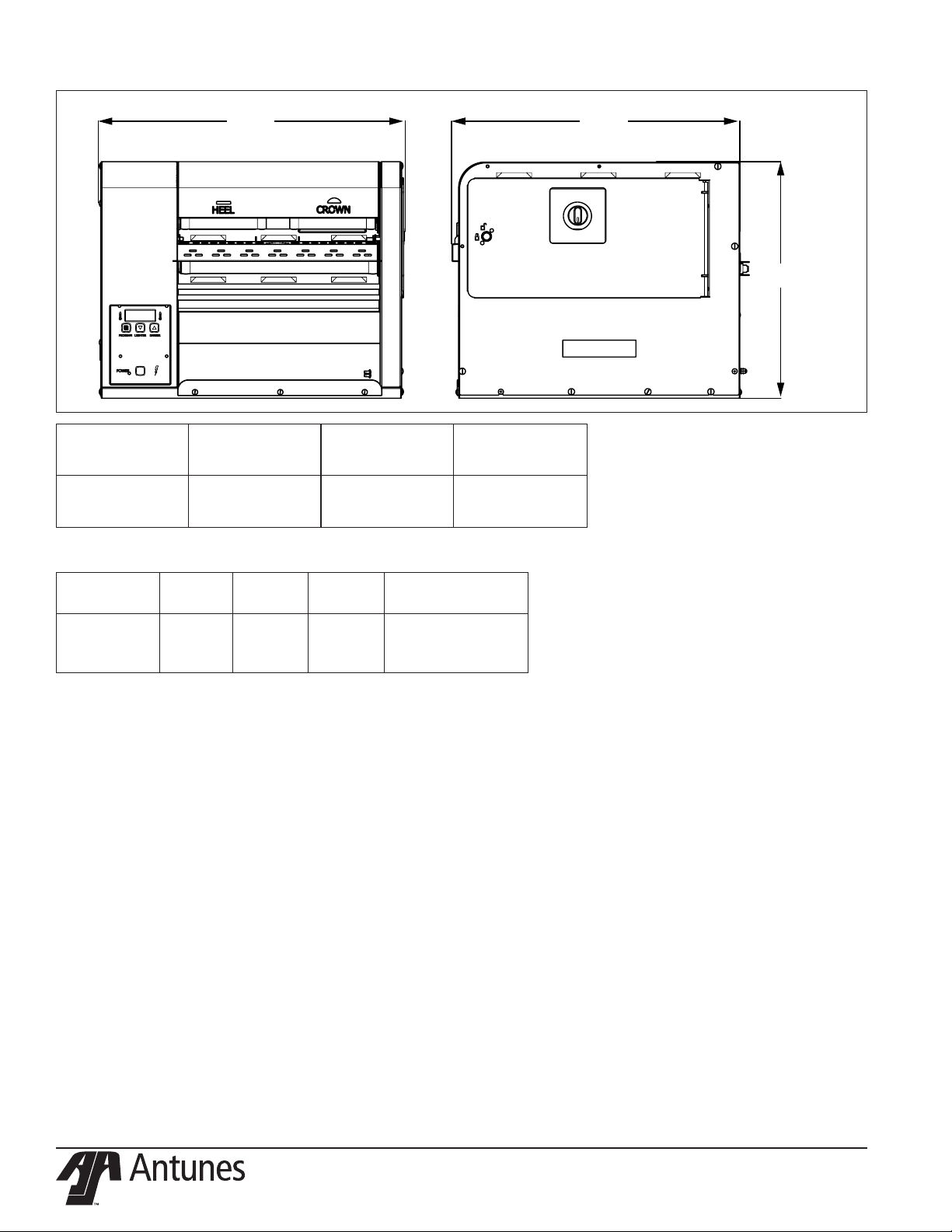
Specications
A B
C
Model &
Mfg. No.
GST-2H
9210888
Model &
Mfg. No.
GST-2H
9210888
Width
(A)
22" (559 mm) 21" (533 mm) 17” (432 mm)
Volts Watts Hertz
208 2000 60
Depth
(B)
Plug
Description
NEMA 6-20P
20 Amp, 250 Volt
Right Angle
Height
(C)
4
P/N 1011283 Rev. F 06/18
Page 5
Installation
1. Remove toaster and all packing
materials from shipping carton.
2. Open the Accessories Box. It
should contain the following:
y Bun Chute
y Bun Feeder
y 1 Belt Set
y Owner’s Manual
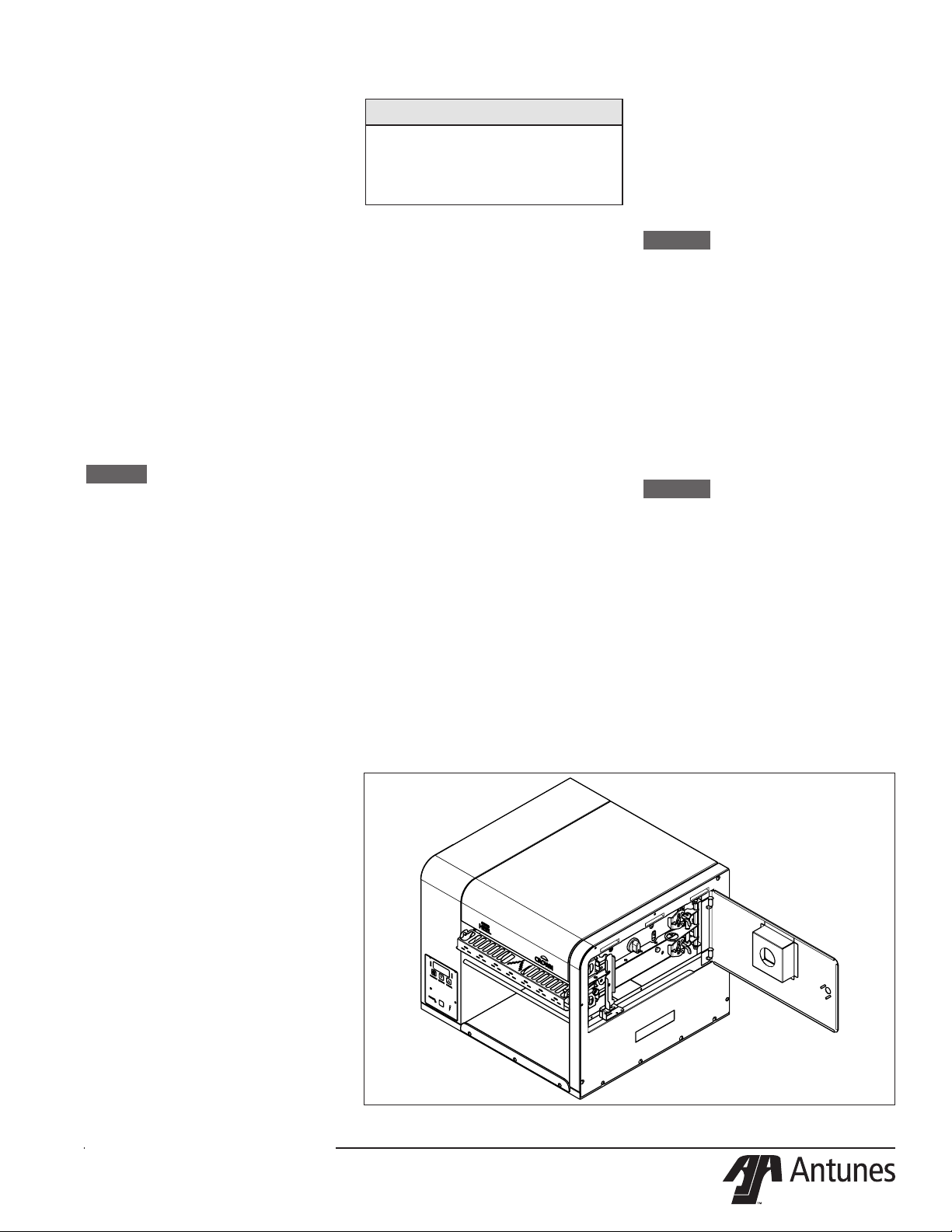
3. Open the side door (Figure
1) and remove all of the plastic ties securing the toaster
mechanism.
4. Remove all packing materials
and protective coverings from the
toaster.
5. Wipe the entire exterior of the
toaster and the accessories mentioned above with a hot damp cloth.
Allow to air dry
NOTICE: Do NOT use a dripping wet
cloth. Wring out before use.
6. Attach the Bun Chute, Bun Feeder,
and Butter Wheel assembly.
7. Make sure the Compression Knob
is set to 3, the default setting.
When placing the toaster into service,
pay attention to the following guidelines.
y The power cord is located
at the bottom of the toaster.
The toaster is designed to
be placed on a table that will
NOT pinch the power cord.
y Make sure the power switch
is off and the toaster is at
room temperature before
plugging in the power cord.
y Do not block or cover any
openings on the toaster.
y Do not immerse the power
cord or plug in water.
y Keep the power cord away
from heated surfaces.
y Do not allow the power
cord to hang over edge
of table or counter.
y Place the toaster on a sturdy,
level table or other work surface.
y Turn the power switch to
off (if it is set to on).
y Ensure the line voltage
corresponds to the stated voltage
on the specification label and
power cord warning tag.
8. Plug the power cord into the appropriate power outlet. Refer to the
specication plate for the proper
voltage.
NOTICE
If any parts are missing or
damaged, contact Antunes
Customer Service immediately at
+1-877-392-7856 (toll free).
Operation
1. Press and release the Power
button to turn the toaster on. Allow the toaster to warm up until
USE appears in the display
2. Set the Compression Knobs to
the desired setting. The recommended Compression Settings
are:
CROWN-#4
HEEL - #3
3. Insert product into the appropriate lane on the Bun Feeder
according to Bun Feeder labels.
Insert buns with the cut side
facing down.
4. Finished product drops into the
Figure 1. Gold Standard Toaster
bun landing zone.
Light/Dark Adjustments
The light/dark value can be adjusted when the toaster is displaying
“USE”. To adjust the light/dark value,
press the LIGHTER or DARKER
button. The display will change to
show the current light/dark value.
NOTICE: The default light/dark
value is d0.
Press the LIGHTER or DARKER
buttons to change the light/dark
value. The adjustment range is L1L9 and d0-d9. L9 is the lightest, d0
is the middle, and d9 is the darkest
setting.
To save the light/dark value, press
the PROGRAM button or wait 5
seconds until the screen displays
“USE”.
NOTICE: Adjusting the light/dark
value does NOT change the
temperature. It changes the
speed of the conveyors. The
light/dark value will reset to
the default value of d0 when
the toaster is turned o.
P/N 1011283 Rev. F 06/18
5
Page 6
User Mode
User Mode allows an operator to
view the toaster settings but does
not permit any adjustments.
1. Press and hold the PROGRAM
button for 5 seconds. After 5
seconds, the display will show
the actual temperature of the
Platen.
2. Press the LIGHTER button to
toggle between the Set point
and actual temperature of the
Platen Heater.
3. Press the PROGRAM button to
proceed to the Motor Menu. The
display shows the actual speed
of the motor.
4. Press the LIGHTER button to
toggle between the Set point
and actual speed of the Motor.
NOTICE: The toaster will exit User
Mode after 5 seconds of
keypad inactivity.
Manager Mode
Manager Mode allows an operator to view and adjust the following
settings:
y Heater Temperature
y Motor Speed
y Temperature Units
(Celsius or Fahrenheit)
Manager Mode also allows an
operator to view (but not adjust) the
Ambient Temperature of the Control
Compartment.
1. Press and release the Power
button to turn the toaster o.
2. Press and release the Power
button while holding the PRO-
GRAM button. Continue holding
the button until “ENA” appears
on the display (after approximately 10 seconds).
3. Release the PROGRAM button.
The display shows the Heater
Set point Temperature.
4. To adjust the Heater Set point
Temperature, press the LIGHT-
ER or DARKER buttons to
reach the desired temperature.
NOTICE: The recommended
temperature setting for the
Platen is 545 °F (285 °C).
5. Press the PROGRAM button to
procedure to the Motor Speed
Set point.
6. Adjust the Motor Speed Set
point by pressing the LIGHTER
or DARKER buttons to reach
the desired speed.
NOTICE: The Motor Speed is
adjustable from 1-100. The
recommended setting is 57.
7. Press the PROGRAM button
to proceed to the Temperature
Units.
8. To change the Temperatures
units from Fahrenheit or Celsius, press the LIGHTER or
DARKER buttons.
9. Press and hold the PROGRAM
button to save any changes.
NOTICE: The toaster exits Manager
Mode after 30 seconds of
keypad inactivity.
Safety Features
Hi-Limit Control
A Hi-Limit Control turns o electrical
power to the heaters and control circuits and displays HL if the toaster
overheats. To reset the control:
1. Let the toaster cool for 15 minutes.
2. Locate the Hi-Limit Controls on
the rear of the toaster. Remove
the black protective cap.
3. Press and release the button.
Re-install the protective cap.
NOTICE: If the Hi-Limit Control re-
quires continuous resetting,
contact Antunes Technical
Service.
Purging buns from Toaster
If buns get stuck in the toaster,
press and hold both the UP and
DOWN arrow buttons to increase
the belt speed until the buns are
purged from the toaster.
Fault Messages
The toaster displays fault messages
when there is a problem with the
toaster.
y “Hi” ashes if the Platen
Heater temperature is 30°F
more than the Set point or
if the Platen Thermocouple
is disconnected or open.
y “CHEC” ashes when the
control compartment ambient
temperature is more than
150°F (66°C). All heaters shut
o. The toaster will not restart
until the control compartment
ambient temperature falls
below 140°F (60°C).
y “PO” ashes if the incoming
power drops below 190 volts.
The toaster shuts down.
y “StoP” ashes when the
motor has stopped for seven
continuous seconds.
y “SpEd” ashes when the motor
speed drops 25% below the Set
point for 30 continuous seconds.
y “PLt” slow warmup (2:20 Min)
y “SSr” The Solid State Relay has
shorted - the toaster is running
beyond the set point temperature.
Error Codes
If any of the following Error Codes
appear, press and release the
Power button to turn the toaster o.
Allow the toaster to cool. Then press
and release the Power button to turn
the toaster on. If the error repeats,
contact Antunes Technical Service
for assistance.
NOTICE: ERR #1, 2 , 3, 5, 6, 7, and
30 to 51: Internal Error. Cycle
the power. If error persists,
replace the board.
Error Description
ERR 8 Motor running when it
should be o.
ERR 9 High Internal Tempera-
ture.
ERR 10Shorted Thermocouple.
ERR
11
Open Thermocouple.
6
P/N 1011283 Rev. F 06/18
Page 7

Daily Cleaning
Clean the Toaster and Belt
Wraps
3. Wipe the exterior surfaces of the
toaster with a clean, sanitizersoaked towel and allow to air
dry.
1. Press and release the Power
button to turn the toaster o.
The toaster enters a 45 minutes
cool-down mode and automatically shuts down when complete.
NOTICE: The belt rollers will con-
tinue turning while in cooldown mode. This allows the
entire belt to be cleaned.
2. Put on heat resistant gloves.
Remove the Top Cover, Feeder,
and Chute (Figure 1).
3. Wash, rinse and sanitize the Top
Cover, Feeder, and Chute at the
3-compartment sink.
Inspect the Belts
NOTICE: Replace any belts that are
torn, folded, missing snaps,
or damaged. Belts should
be removed ONLY during
belt replacement or when
required in a service situation
(see images on page 9 for
examples). Refer to the section titled Replacing Belts for
instructions on removing and
installing belts.
4. Reinstall all accessories (Figure
1).
5. Turn on the and test the toaster
before returning it to operation.
Figure 2. Example of damaged belts
1. Apply a small amount of KAY®
QSR Heat-Activated Grill &
Toaster Cleaner on a non-abrasive pad.
y Wash step – Wipe with the
non-abrasive pad damped with
the Grill & Toaster Cleaner.
y Rinse step – Wipe with a clean
towel dampened with water.
y Sanitize step – Wipe with
a clean towel soaked in
KAYQUAT® II Sanitizer
solution and allow to air dry.
2. Clean the top and bottom belts
(each belt should follow the
Wash-Rinse-Sanitize step).
NOTICE: Repeat Steps 4 and 5
as needed to remove heavy
carbon buildup. Be sure to
wash-rinse-sanitize the belts
completely. Failure to properly clean the belts will shorten
the life of the belts and result
in poor performance.
P/N 1011283 Rev. F 06/18
Figure 3. Replace torn or folded
belts.
Figure 4. Replace the belt if snaps
are missing or damaged.
7
Figure 5. Replace belts that are
wrinkled or distressed around snaps
or with snaps that are loose, dam-
aged, or missing.
Page 8

Quarterly
Remove Belt Wraps and Clean
Rollers
1. Turn the toaster’s power switch
to the o position. The toaster
enters a cool-down mode and
will automatically shut down
when complete.
2. Unplug the power cord once the
cool-down period is complete.
NOTICE: Wait for the cool-down
period to complete before
unplugging the power cord.
3. Remove the bun feeder using
heat-resistant gloves.
NOTICE: Reposition the toaster
as needed to perform these
steps.
4. Unlock the lock on the right side
panel with a athead screwdriver and open the panel. Turn
the compression knobs (there
are 2) to 7.
Upper Frame
Belt Lock
Unlocked
Lower Frame
Belt Lock
Unlocked
Figure 7. Conveyor locks
8. Carefully remove the two top
belts and one bottom belt.
Upper Belt Wraps
Lower Belt
Wrap
Figure 8. Belt Wraps
3. Slide the belts gently over the
appropriate top and bottom
roller. Make sure the belt lines
up properly on the rollers. The
snaps on the belts should face
the inside of the roller.
4. Restore tension on the bottom
belt by pushing UP and OUT
(See Below).
5. Restore the tension on the top
belt by pushing DOWN and
OUT (See Below).
Tense
Tense
Figure 9. Conveyor rollers under
tension
NOTICE: Lift up on the camshaft of
the rear conveyor roller while
lifting the conveyor lock.
Loose
Loose
Figure 6. Loosening the conveyor
rollers
5. Remove tension on the Top
Belt by pushing the Top FRONT
Roller IN and UP until it locks
into position.
6. Remove tension on the Bottom Belt by pushing the Bottom
FRONT Roller IN and DOWN.
7. Unlock the Top and bottom lock
levers. (Figure 7).
9. Wipe all four rollers and backing plates with a clean, damp
sanitized towel. Make sure to remove all debris from the rollers
and the backing plates so they
are as clean as possible.
10. Use a dry cloth towel or nylonbristled brush to remove all
debris from both side compartments, inside of the toaster, and
underneath the rollers.
Install Belt Wraps
1. If you are installing the existing
belt wraps, inspect the belts.
Replace belt wraps if worn or
damaged. If the belt wraps are
in good condition put them back
on the toaster.
2. For new or existing belts, wipe
both sides of the belts with a
clean, damp sanitized towel. Allow to air dry.
Upper Frame
Belt Lock
Engaged
Lower Frame
Belt Lock
Engaged
Figure 10. Belt frame locks
6. Engage the top and bottom lock
levers as shown above. Make
sure the lock lever is properly inserted into the slotted grooves.
7. Close the side panel and lock
the lock using a athead screwdriver on the side panel.
8. Set the Crown compression
knob to 4 and the Heel to 3.
9. Re install the top cover and bun
feeder onto the toaster.
10. Plug in the power cord and turn
the toaster on.
8
P/N 1011283 Rev. F 06/18
Page 9

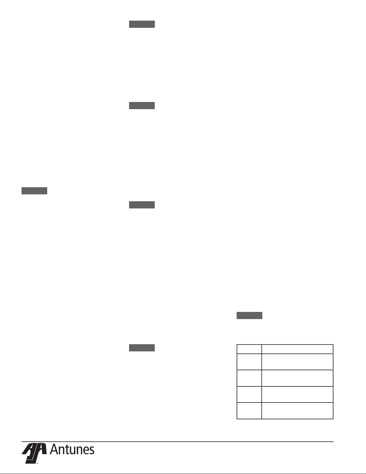
Annual Cleaning
Clean the Cooling Fans and
Electrical Housings
1. Turn the toaster’s power switch
to the o position. The toaster
enters a cool-down mode and
will automatically shut down
when complete. Unplug the
power cord.
2. Remove the push knob and top
six screws on the left side of the
toaster and set aside.
3. Using the handle, remove the
left side cover of the toaster
by lifting up and away from the
toaster. Set aside.
Figure 11. Accessing the cooling fan
4. Remove any debris or dust from
the cooling fan with a small
brush. Wipe away any debris
with a clean, dry towel Inspect
the electrical compartment for
crumbs and debris. Clean out
all crumbs and debris using a
clean, dry towel or nylon bristled
brush. Be careful not to disrupt
any of the electrical wiring.
5. Replace the left side panel
cover by sliding it onto the bottom screws.
6. Reconnect with the screws and
replace Push on Knob.
P/N 1011283 Rev. F 06/18
9
Page 10

Troubleshooting
Problem Possible Cause Corrective Action
Control Display ashes
PLt continuously. Buns
not toasting properly.
Control Display ashes
Er 9 continuously.
Control Display Flashes
SSr continuously. Buns
Burn.
Control Display ashes
Er 11 continuously. Buns
not toasting properly.
Control Display ashes
Er 10 continuously. Buns
not toasting properly.
Control Display ashes
StoP.
Control Display ashes
SpEd.
Crowns and/or Heels
must be forced into the
toaster. Buns sticking
and burning.
Platen temperature is below 545 °F
(285 °C).
Failed Platen Thermocouple. Contact your maintenance person or Antunes
Failed Control Board
Control Compartment ambient temperature is above 150 °F (66 °C)
Failed Cooling Fan.
Failed Control Board
Failed Front Platen Solid State
Relay.
Failed Control Board.
Failed Front Platen Thermocouple.
Loose Platen Thermocouple connection on Control Board or the
Platen Thermocouple is open.
Failed Control Board.
Shorted Platen Thermocouple to
ground.
Failed Control Board
Mechanical bind in one or both
conveyors.
Worn or damaged Ball Bearings.
Drive chain or sprockets damaged.
Failed Motor.
Failed Control Board.
Mechanical bind in one or both
conveyors.
Worn or damaged Ball Bearings.
Conveyor chains loose or damaged.
Drive chain or sprockets damaged.
Belts are dirty, worn, or damaged
(replace every 2-4 months).
Buns do not meet specications. Contact your bun supplier.
Allow the toaster to warm up for 30 minutes and
then recheck. If the Control Display still ashes
PLt, contact your maintenance person or Antunes
Technical Service for service.
Technical Service for service.
Verify side vents on toaster are unblocked and not
near other heating appliances. If problem persists,
contact your maintenance person or Antunes
Technical Service for service.
Contact your maintenance person or Antunes
Technical Service for service.
Re-secure the Platen Thermocouple to the Control
Board. If the Control Display still reads Er 11,
check the Thermocouple for continuity. Contact
your maintenance person or Antunes Technical
Service for service.
Disconnect and re-secure the Platen Thermocouple connection to the Control Board. If the Control
Display still reads Er 10, check the Thermocouple
for continuity. Contact your maintenance person or
Antunes Technical Service for service.
Enter “user mode” to check the motor speed.
Check both conveyors for mechanical binds. Test
the motor. Replace necessary parts. Contact your
maintenance person or Antunes Technical Service
for service.
Enter “user mode” to check motor speed. Check
both conveyors for mechanical binds. Replace
necessary parts. Contact your maintenance person or Antunes Technical Service for service.
Clean or replace Belts as described in the Maintenance section of this manual.
10
P/N 1011283 Rev. F 06/18
Page 11

Problem Possible Cause Corrective Action
Buns not toasting adequately.
Compression Setting is incorrect. Use the recommended setting of 4 for Crowns and
3 for Heels.
One of the Conveyor shafts is stuck
in the lower lock position.
Either both Upper/Lower Conveyor
locks are not properly locked in
Inspect positions of the shafts as described in the
Maintenance section of this manual.
Inspect the proper position of the locks as described in the Maintenance section of this manual.
place.
Buns do not meet specications. Contact your bun supplier.
Motor settings are incorrect. Verify that the motor setting is set to 4000 as
described in the Programming section of this
Manual.
Compression side door
will not close.
Either both Upper/Lower Conveyor
Locks are not properly locked in
Inspect the proper position of the locks as described in the Maintenance section of this manual.
place.
The lock on the Compression Side
Door is in the locked position when
Turn the lock to the unlocked position before closing the door.
trying to close the door.
Fan is making an unusual sound.
Failed Cooling Fan. Verify vents on toaster are unblocked and not near
Cooling Fan is dirty and needs to be
cleaned.
other heating appliances. Clean fans as described
in the Maintenance section of this manual. If problem persists, contact your maintenance person or
Antunes Technical Service for service.
Control Display ashes
HL continuously. Buns
are not toasting properly.
Hi-Limit Control is tripped. Allow the toaster to cool and reset the Hi-Limit
Control. If it trips again, contact your maintenance
person or Antunes Technical Service for service.
Control Display is blank. Power Cord is not plugged in. Plug the Power Cord into the appropriate out-
let. Turn the toaster on. If the Control Display is
still blank, contact your maintenance person or
Antunes Technical Service for service.
Circuit Breakers turned o or
tripped. Damaged electrical outlet,
plug, or Power Cord. Power Switch
damaged.
Reset Circuit Breakers. If they trip again, check
the Power Cord, Plug, and outlet for damage.
Contact your maintenance person, Authorized
Service Agency, and Electrician for service.
Faulty Transformer. Replace Transformer.
Conveyors not turning. Belt is damaged. Replace Belts
Motor Drive Chain is detached from
Reinstall the Drive Chain.
sprockets.
Failed Drive Motor. Contact your maintenance person or Antunes
Technical Service for service.
Belts are ripped or torn. Rollers or Heater Cover Plates are
dirty and need to be cleaned.
Clean Rollers and Heater Cover Plates as outlined
in the Maintenance section of this manual.
Belts are not installed properly. Install Belts correctly as outlined in the Mainte-
nance section of this manual.
Roller(s) in the incorrect locked
Unlock Rollers to operational position.
position during operation.
Front Conveyor Lock is disengaged. Engage and lock the Front Conveyor Lock.
P/N 1011283 Rev. F 06/18
11
Page 12

Replacement Parts
50
26
64
43
23
40
35
64
45
68
68
78
42
13
82
52
31
52
56
42
14
82
6
18
39
64
33
68
6824
30
66
56
9
66
9
49
51
2
17
50
NOTICE
Use only genuine Antunes replacement parts in this
egg station. Use of parts other than those supplied by
the manufacturer will void the warranty.
See next page for replacement parts list
64
12
P/N 1011283 Rev. F 06/18
Page 13

Parts List
Item
No.
1 0012913 Insulator Assembly 1
2 0012961 Door Assembly 1
3 0013024 Platen Assembly 1
4 0013025 Drive Motor Assy 1
5 0013093 Brkt Assy Top 1
6 0013094 Brkt Assy Bottom
7 0013095 Bearing Brkt Assy 2
8 0013096 Adjustable Frame Assy
9 0013104 Brg Cover Assy 2
10 0013109 Duct Assembly 1
11 0013110 Housing Door Assy 1
12 0013111 Assy, Drive Chain Tensioner 1
13 0021724
14 0021725
15 0021865 Main Platen Frame Wldmt 1
16 0021885 End Housing Weldment
17 0021897 End Housing Panel Wldmt 1
18 0021940 Base Weldment
19 0021953
20 0021954 Weldment, Idler Adjust Lanes 1
21 0021976
22 0021977
23 0022007 Top Hinge Lock Weldmt 1
24 0022008 Bottom Hinge Lock Weldmt 1
25 0022043 Control Housing Weldment 1
26 0022105 Cover Weldment 1
27 0400119 Bushing, Shorty 5/8” 3
28 0400315 Strain Relief 1
29 0400432 Bushing, Open/Closed 1
30 0506543 Plate, Tensioner LH 1
31 0506544 Plate, Tensioner RH 1
32 0506556 Base Bottom Side 1
33 0506562 Ele Cover 1
34 0506566 Plate, Tensioner 2
35 0506835 Bun Stop 1
36 0506836 Washer 1
37 0506839 Bearing Retainer Brkt 1
38 0506853 Frame Cover 1
39 0506860 Back Cover 1
40 0506864 Bun Ramp 1
41 0600143 Spring, Compression Setting 1
42 0600158 Spring, Roller Tension
43 0600161
44 0700737
45 0800467 Bun Chute 1
46 0800473 Rod, Hsg Spacer 14.375 Lg 4
48 1001505 Label, Control 1
49 1001586 Label, Compression- RH 1
50 2100212 Handle, Pocket Pull, Snap-In 2
51 2100253 Knob, 1/4” Shaft, Push-On 2
Part # Description Qty.
Weldment, Brg Brkt & Spring
Guide - RH
Wldmnt, Bearing Brkt & Spring
Guide LH
Weldment, Drive Roller Adjust
Lanes
Wldmt, Drive Roller Main
Platen
Wldmt, Idler Roller Main
Platen
Torsion Spring, Locking
Bracket Top
Power Cord 20A, 250V Right
Angle
Item
Part # Description Qty.
No.
52 2100334 Thrust Strip, Teon 4
53 2110197 Clip, Steel Cable 1
54 2120233
55 2150185 Sprocket, 25B18, 1/2” Bore 2
56 2150384
1
1
2
57 2150393 Drive Chain 1
58 304P105 Nut, Hex ‘Keps’ #4-40 5
59 306P130
60 308P124 Screw, Mach One-Way #8-32 1
61 308P143 Nut, Hex ‘Keps’ #8-32 2
62 308P145
63 308P199 Nut, Hex ‘Keps’ #8-32
64 308P203
2
65 310P102
1
1
1
66 310P146 Nut, Hex ‘Keps’ #10-32 26
67 310P187
68 310P196 Screw, Shoulder 10-32 SS 4
69 310P199
1
70 310P204
1
71 310P214 Screw, Hex #10-32 X 1/2” 4
72 325P109
73 325P154
Spacer .252 Id X .5 Od X
.925” Lg
Bearing Assy, Hi-Temp 1 1/8”
Od X 1/2” Id
Nut, Hex Keps #6-32 (Small
Pattern)
Nut, Hex Acorn #08-32 Low
Crown
Screw, Tap 8-32 X 3/8” W/
Int. Tth Washer
Washer, Int. Tooth-
Lock,#10
Screw Set, #10-32 X 3/8
Hex S Socket-Cone Point
Scr, #10-32 X 3/8 Lg
Socket Hd Cap
Fillister Head Phillips
Screw # 10-32 X .25
Screw, Hexcap 1/4-20 X
1/2”
Washer, Ø1/4” Helical
Spring Lock
4
8
9
1
33
8
2
8
2
9
4
74 325P177 Screw, Shoulder 5/16 SD 1
75 325P193
Screw, Hex Head, #1/4-20
X 1.375”, SS
4
76 4010221 Cap-Mp, Motor Run 1
77 4030352 Thermostat, Hi-Limit 700°F
78 4030446
79 4050214
Htr, Foil 208V, 35W .25
Female Terminals
Thermocouple Type “K”
(Open End)
1
1
1
80 4060374 Ground Lug 1
81 4070183
Assy-PCB, VCT W/ Power
Switch
1
82 5040022 Bottom Gasket 4
4
1
1
84 7000984 Main Belt 1
85 7000991 Crown & Heel Belt
* Available in Packages of ten (10)
2
P/N 1011283 Rev. F 06/18
13
Page 14

PARTS LIST
ITEM
PART NO. DESCRIPTION
QTY
4.9 3100199
SCR, #10-32 X 3/8 LG SOCKET
HD CAP
4
85 3100199
SCR, #10-32 X 3/8 LG SOCKET
HD CAP
8
4.9, 85
3100199
SCR, #10-32 X 3/8 LG SOCKET
HD CAP
12
1
0013024
PLATEN ASSY
1
2
0013093
BRKT ASSY TOP
1
3 0013094
BRKT ASSY BOTTOM
1
4
0013095
BEARING BRKT ASSY
2
5
0013096
ADJUSTABLE FRAME ASSY
1
6 0013104
BRG COVER ASSY
2
7
0013111
ASSY, DRIVE CHAIN
TENSIONER
1
8 0021724
WELDMENT, BRG BRKT &
SPRING GUIDE - RH
2
9 0021725
WEDMENT, BEARING
BRACKET & SPRING GUIDE -
LH
2
10 0021865
MAIN PLATEN FRAME WLDMT
1
11
0021885
END HOUSING WELDMENT
1
12
0021894
WELDMENT, END COVER
LOCK
1
13 0021895
DOOR WELDMENT
1
14
0021897
END HOUSING PANEL WLDMT
1
15 0021916
ELE BRACKET WLDMT
1
17
0021950
PANEL WELDMENT CONTROL
HSG
1
18 0021953
WELDMENT, DRIVE ROLLER
ADJUST LANES
1
19 0021954
WELDMENT, IDLER ADJUST
LANES
1
20 0021976
WLDMT, DRIVE ROLLER MAIN
PLATEN
1
21
0021977
WLDMT, IDLER ROLLER MAIN
PLATEN
1
PARTS LIST
ITEM
PART NO. DESCRIPTION
QTY
22
0022007
TOP HINGE LOCK WELDMT
1
23 0022008
BOTTOM HINGE LOCK
WELDMT
1
24
0022043
CONTROL HOUSING
WELDMENT
1
25 0022105
COVER WELDMENT
1
26 0400119
BUSHING, SHORTY 5/8"
3
27
0400251
STRAIN RELIEF-CORD
CONNECTOR
1
28 0400432
BUSHING, OPEN/CLOSED
1
29 0506083
SPACER .075 THK .203 ID X
.312 OD
2
30 0506157
MOTOR PLATE
1
31 0506543
PLATE, TENSIONER LH
1
32 0506544
PLATE, TENSIONER RH
1
33 0506556
BASE BOTTOM SIDE
1
34 0506562
ELE COVER
1
35 0506566
PLATE, TENSIONER
2
36 0506835
BUN STOP
1
37 0506836
WASHER
1
38 0506839
BEARING RETAINER BRKT
1
39 0506853
FRAME COVER
1
40 0506860
BACK COVER
1
41
0506862
DUCT
1
42
0506864
BUN RAMP
1
43 0600143
SPRING, COMPRESSION
SETTING
1
44
0600158
SPRING, ROLLER TENSION
4
PARTS LIST
ITEM
PART NO. DESCRIPTION
QTY
45
0600161
TORSION SPRING, LOCKING
BRACKET TOP
1
46 0700737
POWER CORD 20A, 250V
RIGHT ANGLE
1
47
0800467
BUN CHUTE
1
48 0800473
ROD, HSG SPACER 14.375 LG
4
49 1000136
EMBLEM, ROUNDUP
1
50 1000900
LABEL - WARNING
1
51 1001192
LABEL, CAUTION - "HOT"
1
52 1001213
LABEL - SHOCK HAZARD
1
53 1001505
LABEL, CONTROL
1
54
1001585
LABEL, COMPRESSION LH
1
55
1001586
LABEL, COMPRESSION- RH
1
56 1001589
LABEL, WIRE DIAGRAM
WENDY'S
1
57
2100212
HANDLE, POCKET PULL,
SNAP-IN
1
58 2100212
HANDLE, POCKET PULL,
SNAP-IN
2
58, 57
2100212
HANDLE, POCKET PULL,
SNAP-IN
3
59 2100253
KNOB, 1/4" SHAFT, PUSH-ON
2
60 2100334
THRUST STRIP, TEFLON
4
61 2110197
CLIP, STEEL CABLE
1
62 2120233
SPACER .252 ID X .5 OD X
.925" LG
4
63 2120259
SPACER, .38OD X .13THK #8
SCREW
2
64 2140109
LOCTITE # 242 (BLUE)
1
65 2150185
SPROCKET, 25B18, 1/2" BORE
2
66 2150378
SPROCKET, 25B20 3/8" BORE
1
PARTS LIST
ITEM
PART NO. DESCRIPTION
QTY
67 2150384
BEARING ASSY, HI-TEMP 1
1/8" OD X 1/2" ID
8
68 2150393
DRIVE CHAIN
1
69 3040105
NUT, HEX 'KEPS' #4-40
5
70 3040105
NUT, HEX 'KEPS' #4-40
2
70, 69
3040105
NUT, HEX 'KEPS' #4-40
7
71
3060130
NUT, HEX KEPS #6-32 (SMALL
PATTERN)
9
72
3060130
NUT, HEX KEPS #6-32 (SMALL
PATTERN)
2
72, 71
3060130
NUT, HEX KEPS #6-32 (SMALL
PATTERN)
11
73 3080124
SCREW, MACH ONE-WAY
#8-32
1
74
3080143
NUT, HEX 'KEPS' #8-32
2
75
3080145
NUT, HEX ACORN #08-32 LOW
CROWN
1
76 3080199
NUT, HEX 'KEPS' #8-32
4
77
3080203
SCREW, TAP 8-32 X 3/8"
W/INT. TOOTH WASHER
4
78 3080203
SCREW, TAP 8-32 X 3/8"
W/INT. TOOTH WASHER
33
78, 77
3080203
SCREW, TAP 8-32 X 3/8"
W/INT. TOOTH WASHER
37
79 3080223
WASHER, FLAT #8
2
80 3080340
NUT, HEX ACORN LOCK #8-32
2
81
3100102
WASHER, INT.
TOOTH-LOCK,#10
8
82 3100146
NUT, HEX 'KEPS' #10-32
26
83 3100187
SCREW SET, #10-32 X 3/8 HEX
SOCKET-CONE POINT
2
84 3100196
SCREW, SHOULDER 10-32 SS
4
87 3100204
FILLISTER HEAD PHILLIPS
SCREW # 10-32 X .25
2
88 3100213
SCREW, PHPNHD #10-16 X
3/4" THRD FORM
4
PARTS LIST
ITEM
PART NO. DESCRIPTION
QTY
89 3100214
SCREW, HEX #10-32 X 1/2"
4
90 3250109
SCREW, HEXCAP 1/4-20 X 1/2"
9
91 3250154
WASHER, Ă1/4" HELICAL
SPRING LOCK
4
92 3250177
1
93 3250193
SCREW, HEX HEAD, #1/4-20 X
1.375", S.S.
4
94 4000186
MOTOR, 230V
1
95 4000202
FAN, AXIAL - 230V, METAL
HOUSING & IMP
1
96 4010187
TRANSFORMER, 240
VAC/12VAC
1
97 4010221
CAP-MP, MOTOR RUN
1
98 4030352
THERMOSTAT, HI-LIMIT 700ĀF
1
99 4030446
HTR, FOIL 208V, 35W .25
FEMALE TERMINALS
1
100 4050214
THERMOCOUPLE TYPE "K"
(OPEN END)
1
101 4050236
CONTACTOR, 2 POLE NO
1
102 4051010
RELAY, RANDOM PHASE,
SOLID STATE-50A
1
103 4060374
GROUND LUG
1
104 4070154
VARISTOR BOARD
1
105 4070183
1
106 5040022
4
107 5040022a
1
108 7000984
MAIN BELT
1
109 7000991
CROWN & HEEL BELT
2
312 0507140
ALUM WASHER
2
313 0013115
BASE ASSEMBLY
1
PARTS LIST
ITEM
PART NO. DESCRIPTION
QTY
4.9 3100199
SCR, #10-32 X 3/8 LG SOCKET
HD CAP
4
85 3100199
SCR, #10-32 X 3/8 LG SOCKET
HD CAP
8
4.9, 85
3100199
SCR, #10-32 X 3/8 LG SOCKET
HD CAP
12
1
0013024
PLATEN ASSY
1
2
0013093
BRKT ASSY TOP
1
3 0013094
BRKT ASSY BOTTOM
1
4
0013095
BEARING BRKT ASSY
2
5
0013096
ADJUSTABLE FRAME ASSY
1
6 0013104
BRG COVER ASSY
2
7
0013111
ASSY, DRIVE CHAIN
TENSIONER
1
8 0021724
WELDMENT, BRG BRKT &
SPRING GUIDE - RH
2
9 0021725
WEDMENT, BEARING
BRACKET & SPRING GUIDE -
LH
2
10 0021865
MAIN PLATEN FRAME WLDMT
1
11
0021885
END HOUSING WELDMENT
1
12
0021894
WELDMENT, END COVER
LOCK
1
13 0021895
DOOR WELDMENT
1
14
0021897
END HOUSING PANEL WLDMT
1
15 0021916
ELE BRACKET WLDMT
1
17
0021950
PANEL WELDMENT CONTROL
HSG
1
18 0021953
WELDMENT, DRIVE ROLLER
ADJUST LANES
1
19 0021954
WELDMENT, IDLER ADJUST
LANES
1
20 0021976
WLDMT, DRIVE ROLLER MAIN
PLATEN
1
21
0021977
WLDMT, IDLER ROLLER MAIN
PLATEN
1
PARTS LIST
ITEM
PART NO. DESCRIPTION
QTY
22
0022007
TOP HINGE LOCK WELDMT
1
23 0022008
BOTTOM HINGE LOCK
WELDMT
1
24
0022043
CONTROL HOUSING
WELDMENT
1
25 0022105
COVER WELDMENT
1
26 0400119
BUSHING, SHORTY 5/8"
3
27
0400251
STRAIN RELIEF-CORD
CONNECTOR
1
28 0400432
BUSHING, OPEN/CLOSED
1
29 0506083
SPACER .075 THK .203 ID X
.312 OD
2
30 0506157
MOTOR PLATE
1
31 0506543
PLATE, TENSIONER LH
1
32 0506544
PLATE, TENSIONER RH
1
33 0506556
BASE BOTTOM SIDE
1
34 0506562
ELE COVER
1
35 0506566
PLATE, TENSIONER
2
36 0506835
BUN STOP
1
37 0506836
WASHER
1
38 0506839
BEARING RETAINER BRKT
1
39 0506853
FRAME COVER
1
40 0506860
BACK COVER
1
41
0506862
DUCT
1
42
0506864
BUN RAMP
1
43 0600143
SPRING, COMPRESSION
SETTING
1
44
0600158
SPRING, ROLLER TENSION
4
PARTS LIST
ITEM
PART NO. DESCRIPTION
QTY
45
0600161
TORSION SPRING, LOCKING
BRACKET TOP
1
46 0700737
POWER CORD 20A, 250V
RIGHT ANGLE
1
47
0800467
BUN CHUTE
1
48 0800473
ROD, HSG SPACER 14.375 LG
4
49 1000136
EMBLEM, ROUNDUP
1
50 1000900
LABEL - WARNING
1
51 1001192
LABEL, CAUTION - "HOT"
1
52 1001213
LABEL - SHOCK HAZARD
1
53 1001505
LABEL, CONTROL
1
54
1001585
LABEL, COMPRESSION LH
1
55
1001586
LABEL, COMPRESSION- RH
1
56 1001589
LABEL, WIRE DIAGRAM
WENDY'S
1
57
2100212
HANDLE, POCKET PULL,
SNAP-IN
1
58 2100212
HANDLE, POCKET PULL,
SNAP-IN
2
58, 57
2100212
HANDLE, POCKET PULL,
SNAP-IN
3
59 2100253
KNOB, 1/4" SHAFT, PUSH-ON
2
60 2100334
THRUST STRIP, TEFLON
4
61 2110197
CLIP, STEEL CABLE
1
62 2120233
SPACER .252 ID X .5 OD X
.925" LG
4
63 2120259
SPACER, .38OD X .13THK #8
SCREW
2
64 2140109
LOCTITE # 242 (BLUE)
1
65 2150185
SPROCKET, 25B18, 1/2" BORE
2
66 2150378
SPROCKET, 25B20 3/8" BORE
1
PARTS LIST
ITEM
PART NO. DESCRIPTION
QTY
67 2150384
BEARING ASSY, HI-TEMP 1
1/8" OD X 1/2" ID
8
68 2150393
DRIVE CHAIN
1
69 3040105
NUT, HEX 'KEPS' #4-40
5
70 3040105
NUT, HEX 'KEPS' #4-40
2
70, 69
3040105
NUT, HEX 'KEPS' #4-40
7
71
3060130
NUT, HEX KEPS #6-32 (SMALL
PATTERN)
9
72
3060130
NUT, HEX KEPS #6-32 (SMALL
PATTERN)
2
72, 71
3060130
NUT, HEX KEPS #6-32 (SMALL
PATTERN)
11
73 3080124
SCREW, MACH ONE-WAY
#8-32
1
74
3080143
NUT, HEX 'KEPS' #8-32
2
75
3080145
NUT, HEX ACORN #08-32 LOW
CROWN
1
76 3080199
NUT, HEX 'KEPS' #8-32
4
77
3080203
SCREW, TAP 8-32 X 3/8"
W/INT. TOOTH WASHER
4
78 3080203
SCREW, TAP 8-32 X 3/8"
W/INT. TOOTH WASHER
33
78, 77
3080203
SCREW, TAP 8-32 X 3/8"
W/INT. TOOTH WASHER
37
79 3080223
WASHER, FLAT #8
2
80 3080340
NUT, HEX ACORN LOCK #8-32
2
81
3100102
WASHER, INT.
TOOTH-LOCK,#10
8
82 3100146
NUT, HEX 'KEPS' #10-32
26
83 3100187
SCREW SET, #10-32 X 3/8 HEX
SOCKET-CONE POINT
2
84 3100196
SCREW, SHOULDER 10-32 SS
4
87 3100204
FILLISTER HEAD PHILLIPS
SCREW # 10-32 X .25
2
88 3100213
SCREW, PHPNHD #10-16 X
3/4" THRD FORM
4
PARTS LIST
ITEM
PART NO. DESCRIPTION
QTY
89 3100214
SCREW, HEX #10-32 X 1/2"
4
90 3250109
SCREW, HEXCAP 1/4-20 X 1/2"
9
91 3250154
WASHER, Ă1/4" HELICAL
SPRING LOCK
4
92 3250177
1
93 3250193
SCREW, HEX HEAD, #1/4-20 X
1.375", S.S.
4
94 4000186
MOTOR, 230V
1
95 4000202
FAN, AXIAL - 230V, METAL
HOUSING & IMP
1
96 4010187
TRANSFORMER, 240
VAC/12VAC
1
97 4010221
CAP-MP, MOTOR RUN
1
98 4030352
THERMOSTAT, HI-LIMIT 700ĀF
1
99 4030446
HTR, FOIL 208V, 35W .25
FEMALE TERMINALS
1
100 4050214
THERMOCOUPLE TYPE "K"
(OPEN END)
1
101 4050236
CONTACTOR, 2 POLE NO
1
102 4051010
RELAY, RANDOM PHASE,
SOLID STATE-50A
1
103 4060374
GROUND LUG
1
104 4070154
VARISTOR BOARD
1
105 4070183
1
106 5040022
4
107 5040022a
1
108 7000984
MAIN BELT
1
109 7000991
CROWN & HEEL BELT
2
312 0507140
ALUM WASHER
2
313 0013115
BASE ASSEMBLY
1
59
59
59
54
54
54
57
57
57
98
98
41
41
41
95
95
95
88
88
88
71
71
71
104
104
52
52
52
50
50
50
104
78
78
78
17
17
17
70
70
70
7
7
7
96
96
96
77
77
77
72
72
72
101
101
101
83
83
83
65
65
65
30
30
30
65
65
65
83
83
83
89
89
89
43
43
43
66
66
66
102
102
102
77
77
77
15
15
15
67
67
67
38
38
38
82
82
82
94
94
60
60
60
35
35
35
100
100
100
4.9
4.9
4.9
67
67
67
4
4
4
67
67
67
4
4
4
82
82
82
71
71
71
44
44
44
60
60
60
35
35
35
44
44
44
8
8
8
46
46
46
76
76
76
76
76
76
27
27
27
9
9
53
53
53
105
105
105
NOTICE
Use only genuine Antunes replacement parts in this
egg station. Use of parts other than those supplied by
the manufacturer will void the warranty.
See next page for replacement parts list
14
P/N 1011283 Rev. F 06/18
Page 15

Parts List
Item
No.
1
2
3
4
5
6
7
8
9
10
11
12
13
14
15
17
18
19
20
21
22
23
24
25
26
27
28
29
30
31
32
33
34
35
36
37
38
39
40
41
42
43
44
45
46
47
48
50
51
52
53
54
Part # Description Qty.
0013024 Platen Assembly
0013093 Brkt Assy Top
0012094 Brkt Assy Bottom
0013095 Bearing Brkt Assy
0013096 Adjustable Frame Assy
0013104 Brg Cover Assy.
0013111
0021724
0021725
0021965
Assy, Drive Chain
Tensioner
Weldment, Brg. Brkt. &
Spring Guide RH
Weldment, Brng Brkt &
Spring Guide LH
Main Platen Frame
Weldment
0021885 End Housing Weldment
0021894 Weldment, End Cover Lock
0021895 Door Weldment
0021897
End Housing Panel
Weldment
0021916 Ele. Bracket Weldment
0021950
0021953
0021954
0021976
0021977
Panel Weldment Control
Hsng.
Weldment, Drive Roller Adj.
Lanes
Weldment, Idler Adjust
Lanes
Wldmnt, Drive Roller Main
Platen
Weldment, Idler, Roller-
Main Platen
0022007 Top Hinge Lock Wldmnt
0022008 Bottom Hinge Lock Wldmnt
0022043 Control Housing Weldment
0022105 Cover Weldment
0400119 Busing, Shorty 5/8”
0400251 Strain Relief
0400432 Bushing, Open/Closed
0506083
Spacer, .075 Thk .203 ID X
.3112 OD
0506157 Motor Plate
0506543 Plate, Tensioner LH
0506544 Plate Tensioner RH
0506556 Base Bottom Side
0506562 Ele. Cover
0506566 Plate, Tensioner
0506835 Bun Stop
0506836 Washer
0506839 Bearing Retainer Brckt.
0506853 Frame Cover
0506860 Back Cover
0506862 Duct
0506864 Bun Ramp
0600143
Spring, Compression Set-
ting
0600158 Spring, Roller Tension
0600161
0700737
Torsion Spring, Locking
Bracket Top
Power Cord 20 A 250 V
Right Angle
0800467 Bun Chute
0800473
Rod, Hsg. Spacer 14.375
LG
1000900 Label, Warning
1001192 Label, Caution Hot
1001213 Label, Shock Hazard
1001505 Label, Control
1001585 Label, Compression LH
Item
Part # Description Qty.
No.
55
1
1
1
2
1
2
1
2
2
1
1
1
1
1
1
1
1
1
1
1
1
1
1
1
3
1
1
2
1
1
1
1
1
2
1
1
1
1
1
1
1
1
4
1
1
1
4
1
1
1
1
1
56
57
59
60
61
62
63
65
66
67
68
69
71
73
74
75
76
77
79
80
81
82
83
84
87
88
89
90
91
92
93
94
95
96
97
98
99
100
101
102
103
104
105
106
108
109
1001586 Label, Compression RH
1001589 Label, Wiring Diagram
2100212
Handle, Pocket Pull Snap
In
2100253 Knob, 1/4” Shaft, Push on
2100334 Thrust Strip
2100197 Clip, Steel Cable
2120233
2120259
Spacer .252 ID X .5 OD X
.935” LG
Spacer .38 OD X .13 THK
#8 Screw
2150185 Sprocket, 25B18, 1/2” Bore
2150378 Sprocket, 25B20 3/8” Bore
2150484
Bearing Assy, Hi-Temp 1
1/8” OD X 1/2: ID
2150393 Drive Chain
304P105 Nut, Hex KEPS #4-40
206P130
308P124
Nut, HEX KEPS #6-32
(Small Pttrn)
Screw, Mach One Way
#8-32
308P243 Nut, Hex Keps #8-32
308P145
Nut, HEX Acorn #08-32
Low Crown
308P199 Nut, HEX KEPS #8-32
308P203
Screw, Tap 8-32 X 3/8” W
IntTooth Wshr
308P223 Washer, Flat #8
308P340 Nut, Hex Acorn Lock #8-32
310P102 Washer, IntTooth Lock #10
310P146 Nut, Hex KEPS #10-32
310P187
Screw Set, #10-32 x 3/8
HEX Socket-Cone Point
310P196 Screw, Shoulder 10-32 SS
310P204
310P213
Fillister Head Phillips
Screw #10-32 x .25
Screw, PHPNHD #10-16 X
3/4” THRD Form
310P214 Screw, HEX #10-32 x 1/2”
235P109
325P154
Screw, HEXCAP 1/4-20 x
1/2”
Washer 1/4” Helical Spring
Lock
325P177 Screw, Shoulder 5/16 SD
325P192
Screw, HEX head #1/4-20
x 1.275” SS
4000286 Motor, 230 V
4000202
4010187
Fan, Axial - 230V Metal
Housing & Imp
Transformer 240 VAC 12
VAC
4010221 CAP MP Motor Run
4030352 Thermostat, HiLimit 700
4939446
4050214
Htr, Foil 208V 35W .25
Female Terminals
Thermocouple Type K
Open End
4050236 Contactor, 2 Pole
4051010
Relay, Random Phase
Solid State 50A
4060374 Ground Lug
4070154 Varistor Board
4070183
Assy-PCB, VCT W/ Power
Switch
5040022 Bottom Gasket
7000984 Main Belt
7000991 Crown & Heel Belt
* Available in Packages of ten (10)
1
1
2
2
4
1
4
2
2
1
8
1
1
1
1
1
1
1
1
1
1
1
1
1
1
1
1
1
1
1
1
1
1
1
1
1
1
1
1
1
1
1
1
1
4
1
1
P/N 1011283 Rev. F 06/18
15
Page 16

20
13
2
15
4
15
18
22
24
1
16
8
6
10
5
17
7
27
27
26
19
8
1
16
22
24
18
23
9
11
17
25
12
14
Parts List
Item
No.
1 0013092 Cam Bracket Assy 4
2 0021864 Adjust Frame Wldmt 1
3 0021865 Main Platen Frame Wldmt 1
4 0021953
5 0021954 Weldment, Idler Adjust Lanes 1
6 0021976
7 0021977
8 0022004 Slide Plate Wldmt 4
9 0022005 Crown Plate Wldmt 1
10 0022006 Heel Plate Wldmt 1
11 0100290 Platen, Main 208V, 1900W 1
12 0400458 Insulation, Main Platen 1
13 0506853 Frame Cover 1
14 0507092 Insulation Plate 1
Part # Description Qty.
Weldment, Drive Roller Adjust
Lanes
Wldmt, Drive Roller Main
Wldmt, Idler Roller Main
Platen
Platen
21
3
Item
No.
15 0507140 Alum Washer 2
16 0600162 Spring, Cam 8
17 2120233
1
18 2150362 Cam, Hbcs 4
19 2150376 Shaft Crown 1
Part # Description Qty.
Spacer .252 Id X .5 Od X
.925” Lg
4
20 3080144 Screw, #8-32 X 1/4” (#6 Head) 4
1
1
21 3080164 Screw, Mach. #8-32 X 1” 4
22
23 3100187
24 3100215
25
26
27
16
3080340 Nut, Hex Acorn Lock #8-32
Screw Set, #10-32 X 3/8
HexSocket-Cone Point
Scr, Shldr #10-32 X 1/4”
W/1/4” Shldr Precision
3250193
Screw, Hex Head, #1/4-20
X 1.375”, S.s.
7000984 Main Belt
7000991 Crown & Heel Belt
P/N 1011283 Rev. F 06/18
8
4
8
4
1
2
Page 17

Wiring Diagram
P/N 1011283 Rev. F 06/18
17
Page 18

Limited Warranty
+1 (630) 784-1650
Equipment manufactured by Antunes has been constructed of the finest materials available and manufactured to high quality standards. These units are warranted to be free from electrical and mechanical defects for a period of eighteen (18) month from date
of purchase under normal use and service, and when installed in accordance with manufacturer’s recommendations. To insure
continued operation of the units, follow the maintenance procedures outlined in the Owner’s Manual. During the first 18 months,
electro-mechanical parts, non-overtime labor, and travel expenses up to 2 hours (100 miles/160 km), round trip from the nearest
Authorized Service Center are covered.
This warranty does not cover cost of installation, defects caused by improper storage or handling prior to placing of the Equipment.
This warranty does not cover overtime charges or work done by unauthorized service agencies or personnel. This warranty does
not cover normal maintenance, calibration, or regular adjustments as specified in operating and maintenance instructions of this
manual, and/or labor involved in moving adjacent objects to gain access to the equipment. This warranty does not cover consumable/wear items. This warranty does not cover damage to the Load Cell or Load Cell Assembly due to abuse, misuse, dropping of
unit/shock loads or exceeding maximum weight capacity (4 lbs). This warranty does not cover water contamination problems such
as foreign material in water lines or inside solenoid valves. It does not cover water pressure problems or failures resulting from
improper/incorrect voltage supply. This warranty does not cover Travel Time & Mileage in excess of 2 hours (100 miles/160 km)
round trip from the nearest authorized service agency.
Antunes reserves the right to make changes in design or add any improvements on any product. The right is always reserved to
modify equipment because of factors beyond our control and government regulations. Changes to update equipment do not constitute a warranty charge.
If shipment is damaged in transit, the purchaser should make a claim directly upon the carrier. Careful inspection should be made of the
shipment as soon as it arrives and visible damage should be noted upon the carrier’s receipt. Damage should be reported to the carrier.
This damage is not covered under this warranty.
Warranty charges do not include freight or foreign, excise, municipal or other sales or use taxes. All such freight and taxes are the
responsibility of the purchaser.
THIS WARRANTY IS EXCLUSIVE AND IS IN LIEU OF ALL OTHER WARRANTIES, EXPRESSED OR IMPLIED, INCLUDING ANY IMPLIED WARRANTY OR MERCHANTABILITY OR FITNESS FOR A PARTICULAR PURPOSE, EACH OF
WHICH IS HEREBY EXPRESSLY DISCLAIMED. THE REMEDIES DESCRIBED ABOVE ARE EXCLUSIVE AND IN NO
EVENT SHALL ANTUNES BE LIABLE FOR SPECIAL CONSEQUENTIAL OR INCIDENTAL DAMAGES FOR THE BREACH
OR DELAY IN PERFORMANCE OF THIS WARRANTY.
The warranty does not extend to:
y Damages caused in shipment or damage as result of improper use.
y Installation of electrical service.
y Installation, calibration, or adjustment.
y Normal maintenance outlined in this manual.
y Malfunction resulting from improper service or maintenance.
y Damage caused by improper installation, abuse, or careless handling.
y Damage from moisture getting into electrical components.
y Damage from tampering with, removal of, or changing any preset control or safety device.
y Damage caused by parts or components not provided by Antunes
+1 (630) 784-1000
+1 (800) 253-2991
+86-512-6841-3637
+86-512-6841-3907
 Loading...