

Page 1
Flatbread Toaster
Model GST-1H
Manufacturing Numbers:
9210970 & 9210971
www.antunes.com
P/N 1011446 Rev. B 01/17
Page 2
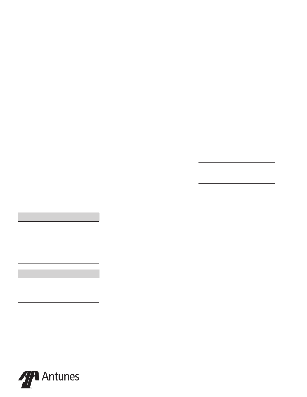
TABLE OF CONTENTS
Table of Contents 2
Warranty
Information 2
Service/Technical
Assistance 2
Important Safety
Information 3
Warnings 3
Specications 4
Installation 5
Operation 5
Light/Dark Adjustments 5
User Mode 6
Manager Mode 6
Safety Features 6
Hi-Limit Control 6
Purging product from Toaster 6
Fault Messages 6
Error Codes 6
Daily Cleaning 7
Replacing Belts 7
Removing Belts 7
Installing Belts 7
Cleaning the Top Cooling Fan and
Electrical Housing (Annually) 8
Troubleshooting 9
Replacement Parts 11
Wiring Diagram 17
NOTES 18
Limited Warranty 20
IMPORTANT
A.J. Antunes & Co. reserves the right to
change specifications and product de-
sign without notice. Such revisions do
not entitle the buyer to corresponding
changes, improvements, additions or
replacements for previously purchased
equipment.
WARRANTY
INFORMATION
Please read the full text of the Limited
Warranty in this manual.
If the unit arrives damaged, contact
the carrier immediately and le a damage claim with them. Save all packing
materials when ling a claim. Freight
damage claims are the responsibility of
the purchaser and are not covered under
warranty.
The warranty does not extend to:
y Damages caused in shipment or
damage as result of improper use.
y Installation of electrical service.
y Normal maintenance as out-
lined in this manual.
y Malfunction resulting from
improper maintenance.
y Damage caused by abuse
or careless handling.
y Damage from moisture into
electrical components.
y Damage from tampering with,
removal of, or changing any
preset control or safety device.
SERVICE/TECHNICAL
ASSISTANCE
If you experience any problems with the
installation or operation of your unit, contact Antunes Technical Service at 877-3927854 Toll Free in the U.S and Canada or at
630-784-0874.
Fill in the information below and have it
handy when calling your Authorized Service Agency for assistance. The serial number is on the specication plate located on
Purchased From
Date of Purchase
Model Number
Serial Number
Manufacturing Number
Use only genuine Antunes replacement
parts in this unit. Use of replacement parts
other than those supplied by the manufacturer will void the warranty.
IMPORTANT
Keep these instructions for future refer-
ence. If the unit changes ownership,
be sure this manual accompanies the
equipment.
2
P/N 1011446 Rev. B 01/17
Page 3

IMPORTANT SAFETY
INFORMATION
Use the following guidelines for safe operation of the unit.
y Read all instructions be-
fore using equipment.
y For your safety, the equipment is
furnished with a properly grounded
cord connector. Do not attempt to
defeat the grounded connector.
y Install or locate the equipment only
for its intended use as described in
this manual. Do not use corrosive
chemicals in this equipment.
y Do not operate this equipment if
it has a damaged cord or plug, if
it is not working properly, or if it
has been damaged or dropped.
y This equipment should be serviced
by qualied personnel only. Contact
your nearest Authorized Service
Agency for adjustment or repair.
y Do not block or cover any
openings on the unit.
y Do not immerse cord
or plug in water.
y Keep cord away from
heated surfaces.
y Do not allow cord to hang over
edge of table or counter.
y Turn the power o, unplug the
power cord, and allow unit to
cool down before performing any
service or maintenance on the unit.
NOTE: Turning o the power switch
does NOT turn o all power to
the unit.
y The procedures in this manual may
include the use of chemical products. These chemical products will
be highlighted with bold face letters
followed by the abbreviated HCS
(Hazard Communication Standard).
See Hazard Communication Standard manual for the appropriated
Material Safety Data Sheets (MSDS).
y The equipment should be grounded
according to local electrical codes to
prevent the possibility of electrical shock. It requires a grounded
receptacle with separate electrical
lines, protected by fuses or circuit
breaker of the proper rating.
y All electrical connections must
be in accordance with local electrical codes and any
other applicable codes.
y Do not clean this appli-
ance with a water jet.
WARNINGS
Be advised of the following warnings
when operating and performing maintenance on this unit.
y If the supply cord is damaged, it
must be replaced by the manufacturer or its service agent or
a similarly qualied person
in order to avoid a hazard.
y Do not modify the power sup-
ply cord plug. If it does not t
the outlet, have a proper outlet
installed by a qualied electrician.
y Do not use an extension
cord with this appliance.
y Electrical ground is re-
quired on this appliance.
y Check with a qualied electrician if
you are in doubt as to whether the
appliance is properly grounded.
y When using a chemical cleaner,
be sure it is safe to use on cast
aluminum. Observe all precautions
and warnings on product label.
y Inspection, testing, and repair
of electrical equipment should
only be performed by qualied service personnel.
y Do not use a sanitizing solution or
abrasive materials. These may cause
damage to the stainless steel nish.
y Chlorides or phosphates in clean-
ing agents (e.g. bleach, sanitizers,
degreasers or detergents) could
cause permanent damage to
stainless steel equipment. The
damage is usually in the form of
discoloration, dulling of metal
surface nish, pits, voids, holes, or
cracks. This damage is permanent
and not covered by warranty.
y The following tips will help
in the maintenance of stainless steel equipment:
• Always use soft, damp cloth for
cleaning, rinse with clear water
and wipe dry. When required,
always rub in direction of metal
polish lines.
• Routine cleaning should be
done daily with soap, ammonia
detergent, and water.
• Stains and spots should be
sponged using a vinegar solution.
• Finger marks and smears should
be rubbed o using soap and
water.
• Hard water spots should be removed using a vinegar solution.
P/N 1011446 Rev. B 01/17
3
Page 4
SPECIFICATIONS
17.25”
(438 mm)
23.4”
(593.4 mm)
(443.3 mm)
17.5”
26”
(661.8 mm)
Model &
Mfg. No.
GST-1H
9210970 &
9210971
Volts Watts Hertz
208 4600 60
Plug
Description
L6-30P 30 Amp.,
250 Volt,
Straight Twist Lock
20”
(510.7 mm)
4
P/N 1011446 Rev. B 01/17
Page 5
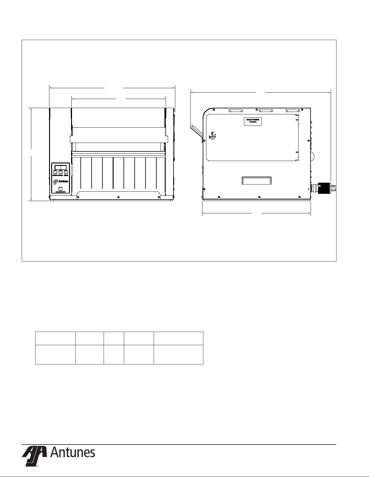
INSTALLATION
CUT AND REMOVE WIRE TIES
BEFORE OPERATING UNIT
1. Remove unit and all packing mate-
rials from shipping carton.
2. Open the Accessories Box. It should
contain the following:
a. Chute
b. Feeder
c. Owner’s Manual
NOTE: If any parts are missing or dam-
aged, contact Antunes Technical Service IMMEDIATELY at
1-877-392-7854 or 1-630-784-
1000.
3. Remove all packing materials and
protective coverings from the unit
and accessories.
4. With assistance, place the unit in
the proper location.
5. Remove the top cover. Wipe the
top cover, chute, and feeder with a
clean sanitizer soaked towel. Allow
to air dry.
6. Wipe the entire exterior of the unit
with a clean sanitizer soaked towel.
Allow to air dry.
NOTE: Do NOT use a dripping wet
cloth. Wring out before use.
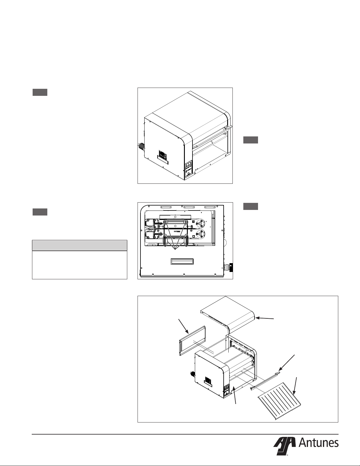
7. Attach the top cover, feeder and
chute (Figure 3).
IMPORTANT
Do NOT plug in the power cord or turn
the unit on before removing the wire
ties indicated in the following step.
Damage to the unit may result.
y Turn the unit o if it is on.
y Ensure the line voltage cor-
responds to the stated voltage
on the specication label and
power cord warning tag.
9. Plug the power cord into the ap-
propriate power outlet. Refer to the
specication plate for the proper
voltage.
Figure 1. - Flatbread Toaster (GST-1H)
OPERATION
1. Press and release the Power button
to turn the toaster on. Allow the
toaster to warm up until USE appears in the display
2. Insert product into the unit using
the feeder.
3. Finished product drops onto the
heated landing zone.
Light/Dark Adjustments
The light/dark value can be adjusted when
the unit is displaying “USE”. To adjust the
light/dark value, press the LIGHTER or
DARKER button. The display will change to
show the current light/dark value.
NOTE: The default light/dark value is
d0.
Press the LIGHTER or DARKER buttons to
change the light/dark value. The adjustment range is L1-L9 and d0-d9. L9 is the
lightest, d0 is the middle, and d9 is the
darkest setting.
To save the light/dark value, wait 5 seconds
until the screen displays “USE”.
NOTE: Adjusting the light/dark value
does NOT change the temperature. It changes the speed of the
conveyors. The light/dark value
will reset to the default value of
d0 when the unit is turned o.
8. Unlock and open the side panel
according to gure 2. Cut and
remove the wire ties indicated in
Figure 2.
When placing the toaster into service, pay
attention to the following guidelines.
y Make sure the unit is o and the
unit is at room temperature before
plugging in the power cord.
y Do not block or cover any
openings on the unit.
y Do not immerse the power
cord or plug in water.
y Keep the power cord away
from heated surfaces.
y Do not allow the power cord to
hang over edge of table or counter.
y Place the unit on a sturdy, level
table or other work surface.
P/N 1011446 Rev. B 01/17
Figure 2. - Removing Wire Ties
BACK PANEL
HEATED LANDING ZONE
Figure 3. - Components
5
TOP COVER
FEEDER
CHUTE
Page 6
USER MODE
User Mode allows an operator to view the
toaster settings but does not permit any
adjustments.
1. Press and hold the PROGRAM but-
ton for 5 seconds. After 5 seconds,
the display will show the actual
temperature of the top Platen.
2. Press the LIGHTER button to toggle
between the Setpoint and actual temperature of the top Platen
Heater.
3. Press the PROGRAM button for 5
seconds. After 5 seconds, the display will show the actual temperature of the bottom Platen.
4. Press the LIGHTER button to toggle
between the Setpoint and actual
temperature of the bottom Platen
Heater.
5. Press the PROGRAM button to
proceed to the Motor Menu. The
display shows actual speed of the
motor.
6. Press the LIGHTER button to toggle
between the Setpoint and actual
speed of the Motor.
NOTE: The unit will exit User Mode af-
ter 5 seconds of keypad inactivity.
MANAGER MODE
Manager Mode allows an operator to view
and adjust the following settings:
y Heater Temperature (front/rear)
y Motor Speed
y Temperature Units
(Celsius or Fahrenheit)
Manager Mode also allows an operator to
view (but not adjust) the Ambient Temperature of the Control Compartment.
1. Press and release the Power button
to turn the toaster o.
2. Press and release the Power button
while holding the PROGRAM button. Continue holding the button
until “ENA” appears on the display
(after approximately 10 seconds).
3. Release the PROGRAM button. The
display shows the Heater Setpoint
Temperature.
4. To adjust the Heater Setpoint
Temperature, press the LIGHTER
or DARKER buttons to reach the
desired temperature.
NOTE: The supplied temperature set-
ting for the Platen is 580 °F (304
°C). It may be set from 500 °F
(260 °C) to 600 F (316 °C)
5. Press the PROGRAM button to
program the motor speed.
6. Adjust the Motor Speed Setpoint by
pressing the LIGHTER or DARKER
buttons to change the motor speed.
NOTE: The Motor Speed is adjustable
from 10-100. The supplied setting for Mfg. No. 9210970 is 98.
The supplied setting for Mfg.
No. 9210971 is 54.
7. Press the PROGRAM button to pro-
ceed to the Temperature Units.
8. To change the Temperatures units
from Fahrenheit or Celsius, press
the LIGHTER or DARKER buttons.
9. Press and hold the PROGRAM button to save any changes.
NOTE: The unit exits Manager Mode
after 30 seconds of keypad inactivity.
SAFETY FEATURES
Hi-Limit Control
A Hi-Limit Control turns o electrical power
to the heaters and control circuits and
displays HL if the unit overheats. To reset
the control:
1. Let the unit cool for 15 minutes.
2. Locate the Hi-Limit Controls on the
rear of the unit. Remove the black
protective cap.
3. Press and release the button. Reinstall the protective cap.
NOTE: If the Hi-Limit Control requires
continuous resetting, contact
your Authorized Service Agency.
Purging product from Toaster
If product gets stuck in the toaster, press
and hold both the UP and DOWN arrow
buttons to increase the belt speed until the
product is purged from the toaster.
Fault Messages
The unit displays fault messages when
there is a problem with the unit.
y “Hi” ashes if the Platen Heater
temperature is 30 °F more than the
Setpoint or if the Platen Thermocouple is disconnected or open.
y “CHEC” ashes when the control
compartment ambient temperature is more than 150 °F (66
°C). All heaters shut o. The unit
will not restart until the control
compartment ambient temperature falls below 140 °F (60 °C).
y “PO” ashes if the incoming
power drops below 190 volts.
The toaster shuts down.
y “StoP” ashes when the mo-
tor has stopped for seven
continuous seconds.
y “SpEd” ashes when the motor
speed drops 25% below the Setpoint for 30 continuous seconds.
y “HL” The Hi-Limit has tripped
and needs to be reset.
Error Codes
If any of the following Error Codes appear,
press and release the Power button to
turn the toaster o. Allow the unit to cool.
Then press and release the Power button
to turn the toaster on. If the error repeats,
contact your Authorized Service Agency
for assistance.
NOTE: ERR #1, 2 , 3, 5, 6, 7, and 30 to
51: Internal Error. Cycle the
power. If error persists, replace
the board.
Error Description
ERR 8 Motor running when it should be
o.
ERR 10 High Internal Temperature.
ERR 11 Shorted Thermocouple.
ERR 12 Open Thermocouple.
ERR 13 Slow warm up.
ERR 14 Shorted Solid State Relay (SSR).
6
P/N 1011446 Rev. B 01/17
Page 7

DAILY CLEANING
1. Press and release the Power button
to turn the toaster o. The toaster
enters a 45 minute cool-down
mode and automatically shuts
down when complete.
NOTE: Be sure to perform cleaning
steps during cool-down mode.
2. Put on neoprene gloves and
remove the feeder, top cover, and
chute.
3. Clean the outside surfaces of the
toaster with clean sanitizer soaked
towel. Allow to air dry.
4. Wipe the feeder, top cover, and
chute with a clean, sanitizer soaked
towel. Allow to air dry.
NOTE: The conveyors continue to turn
during the cool-down period.
5. Inspect the Belts. Replace all of the
belts if any of them are torn, folded,
discolored, missing snaps, or damaged in any way.
NOTE: Replace all Belts if any of the
Belts are discolored, torn, or if
any of the Belt Snaps are damaged.
6. If the Belts are all in good condi-
tion, spray a clean, sanitized towel
with an approved sanitizer. Press
and hold both arrow buttons for
5 seconds. PUR appears on the
display with a blinking cursor. This
locks the belt speed in Purge mode
for 5 minutes to assist in cleaning.
Wipe the top belts clean from the
TOP only. Do NOT insert your hands
between the belts. Wipe the bottom
belt clean from below the belt. Allow to air dry.
7. Press any button to exit Purge
mode.
8. Wipe the top cover clean with a
clean sanitizer soaked towel. Allow
to air dry.
9. Reinstall the top cover, feeder, and
chute.
10. Turn the toaster on and test the unit
before returning it to operation.
NOTE: These cleaning steps may need
to be repeated to remove heavy
carbon buildup.
NOTE: Be sure to clean and sanitize
the Belts completely. Failure
to properly clean the Belts will
shorten the life of the Belts and
result in poor toaster performance.
NOTE: Replace all Belts if any of the
Belts are discolored, torn, or
if any of the Belt Snaps are
damaged. To obtain new Belts,
contact the factory at 1-877392-7854 (North America only)
or 630-784-1000.
NOTE: Belts should be removed ONLY
during Belt replacement or
when required in a service situation.
IMPORTANT
DO NOT INSERT HANDS BETWEEN
THE BELTS. USE CARE WHEN
CLEANING THE BELTS AS THEY ARE
MOVING. PERSONAL INJURY MAY
RESULT!
REPLACING BELTS
Over time, the Belts begin to show signs of
wear. This wear appears in the form of tears
or discoloration of the belt, at which point
all belts should be replaced.
NOTE: Belts should be removed ONLY
during Belt Replacement or
when required in a service
situation. For proper operation,
replace all belts at the same
time.
Removing Belts
1. Press and release the Power button
to turn the toaster o. The toaster
enters a cool-down mode and will
automatically shut down when
complete.
2. Unplug the power cord once the
cool-down period is complete.
3. Put on neoprene gloves. Remove
the feeder.
4. Remove the Top Cover and set
aside.
5. Open the Side Door.
6. Unlock the latch and open the left
side panel.
7. To lock out the Top Conveyor Roller,
face the front of the toaster. Use
both hands and push in on the
Front Conveyor Roller and up. This
removes tension and locks the roller
in place.
8. To lock out the Bottom Roller, face
the front of the toaster. Use both
hands and push in on the Bottom
Conveyor Roller and push down.
This removes tension and locks the
roller in place.
9. Push the front belt frame lock to-
wards the rear of the unit to unlock.
10. Pull the rear Belt Frame Lock out to
disengage.
11. Using a utility knife, cut the existing
Top Belts and remove from the
toaster. Discard the old Belts.
12. Using a utility knife, cut the Lower
Belt and remove from the toaster.
Discard the old Belt.
13. With belts removed, wipe the front
and rear roller rollers and the top
and bottom heater cover plates
with a clean sanitized towel to
remove any debris.
NOTE: Any debris stuck on the roller/
cover plates can damage the
belts
Installing Belts
NOTE: To obtain new Belts, contact
the factory at 1-877-392-7854
(North America only) or 630784-1000.
1. Follow the steps for Removing Belts.
2. Wipe both sides of the new Belts
with a clean, sanitized towel
sprayed with an approved sanitizer
and allow to air dry.
3. Slide the new bottom belt gently
over the bottom front and rear
rollers.
NOTE: Make sure the belt lines up
properly on the rollers. The
snaps on the belts should face
the inside of the top front roller.
4. Slide the Heel/Texas Toaster belt
over the top front and rear rollers.
Repeat this step for the crown belt.
NOTE: Make sure the belt lines up
properly on the rollers. The
snaps on the belts should face
the inside of the top rear roller.
Belts must be installed so the
exposed diagonal seam of the
belt is away from the direction
of belt travel.
5. Return the Top and Bottom Belt
Rollers to full tension by sliding
them back into place.
P/N 1011446 Rev. B 01/17
7
Page 8

6. Slowly close the rear Belt Frame
Lock so the Front and Rear Belt Rollers lock into place.
7. Re-engage the front Belt Frame
Lock by lifting up and then locking
it in place on the Front Conveyor
Assembly.
NOTE: Inform the Store Manager after
any Belt Replacement so new
Belts can be ordered. To obtain
new Belts, contact the factory at
1-877-392-7854 (North America
only) or 630-784-1000.
8. Close and latch the Side Panel.
9. Re-install the Top Cover and Bun
Feeder Assembly.
10. Plug in the toaster and test the unit
before returning to service.
CLEANING THE TOP
COOLING FAN AND ELEC
TRICAL HOUSING ANNU
ALLY
Follow these steps to clean the top fan.
11. Press and release the Power button
to turn the toaster o. The toaster
enters a cool-down mode and will
automatically shut down when
complete.
12. Unplug the power cord.
13. Facing the front of the toaster,
move to the left Side Panel. Remove
the left Side Panel and set aside. Do
not lose the screws.
14. Use a plastic brush or similar tool to
brush all 5 fan blades from above
and below. Be sure to remove all
debris.
15. Carefully clean any debris from the
inside oor of the control compartment and from all electrical connections. Be sure to remove any grease,
lint, or debris from these areas.
16. Reattach the left Side Panel.
8
P/N 1011446 Rev. B 01/17
Page 9

TROUBLESHOOTING
Problem Possible Cause Corrective Action
Control Display ashes PLt continuously. Product not toasting
properly.
Control Display ashes Er 10
continuously.
Control Display Flashes SSr continuously. Product Burns.
Control Display ashes Er 12
continuously. Product not toasting properly.
Control Display ashes Er 11
continuously. Product not toasting properly.
Control Display ashes StoP. Mechanical bind in one or both conveyors. Enter “user mode” to check the motor speed. Check both convey-
Control Display ashes SpEd. Mechanical bind in one or both conveyors. Enter “user mode” to check motor speed. Check both conveyors for
Crowns and/or Heels must be
forced into the toaster. Product
sticking and burning.
Side door will not close. Either both Upper/Lower Conveyor Locks are
Fan is making an unusual sound. Failed Cooling Fan. Verify vents on toaster are unblocked and not near other heating
Control Display ashes HL continuously. Product is not toasting
properly.
Platen temperature is below 545 °F (285 °C). Allow the unit to warm up for 30 minutes and then recheck. If the
Failed Platen Thermocouple. Contact your maintenance person or Authorized Service Agency
Failed Control Board
Control Compartment ambient temperature is
above 150 °F (66 °C)
Failed Cooling Fan.
Failed Control Board
Failed Front Platen Solid State Relay. Contact your maintenance person or Authorized Service Agency
Failed Control Board.
Failed Front Platen Thermocouple.
Loose Platen Thermocouple connection on Control Board or the Platen Thermocouple is open.
Failed Control Board.
Shorted Platen Thermocouple to ground. Disconnect and re-secure the Platen Thermocouple connection to
Failed Control Board
Worn or damaged Ball Bearings.
Drive chain or sprockets damaged.
Failed Motor.
Failed Control Board.
Worn or damaged Ball Bearings.
Conveyor chains loose or damaged.
Drive chain or sprockets damaged.
Belts are dirty, worn, or damaged (replace every
2-4 months).
Product does not meet specications. Contact your product supplier.
One of the Conveyor shafts is stuck in the lower
lock position.
Either both Upper/Lower Conveyor locks are not
properly locked in place.
Product does not meet specications. Contact your product supplier.
Motor settings are incorrect. Verify that the motor setting is set to 4000 as described in the
not properly locked in place.
The lock on the Side Door is in the locked position when trying to close the door.
Cooling Fan is dirty and needs to be cleaned.
Hi-Limit Control is tripped. Allow the unit to cool and reset the Hi-Limit Control. If it trips again,
Control Display still ashes PLt, contact your maintenance person
or Authorized Service Agency for service.
for service.
Verify side vents on toaster are unblocked and not near other
heating appliances. If problem persists, contact your maintenance
person or Authorized Service Agency for service.
for service.
Re-secure the Platen Thermocouple to the Control Board. If the
Control Display still reads Er 11, check the Thermocouple for
continuity. Contact your maintenance person or Authorized Service
Agency for service.
the Control Board. If the Control Display still reads Er 10, check the
Thermocouple for continuity. Contact your maintenance person or
Authorized Service Agency for service.
ors for mechanical binds. Test the motor. Replace necessary parts.
Contact your maintenance person or Authorized Service Agency
for service.
mechanical binds. Replace necessary parts. Contact your maintenance person or Authorized Service Agency for service.
Clean or replace Belts as described in the Maintenance section of
this manual.
Inspect positions of the shafts as described in the Maintenance
section of this manual.
Inspect the proper position of the locks as described in the Maintenance section of this manual.
Programming section of this Manual.
Inspect the proper position of the locks as described in the Maintenance section of this manual.
Turn the lock to the unlocked position before closing the door.
appliances. Clean fans as described in the Maintenance section of
this manual. If problem persists, contact your maintenance person
or Authorized Service Agency for service.
contact your maintenance person or Authorized Service Agency for
service.
P/N 1011446 Rev. B 01/17
9
Page 10

Problem Possible Cause Corrective Action
Control Display is blank. Power Cord is not plugged in. Plug the Power Cord into the appropriate outlet. Turn the toaster
Circuit Breakers turned o or tripped. Damaged
electrical outlet, plug, or Power Cord. Power
Switch damaged.
Faulty Transformer. Replace Transformer.
Conveyors not turning. Belt is damaged. Replace Belts
Motor Drive Chain is detached from sprockets. Reinstall the Drive Chain.
Failed Drive Motor. Contact your maintenance person or Authorized Service Agency
Belts are ripped or torn. Rollers or Heater Cover Plates are dirty and need
to be cleaned.
Belts are not installed properly. Install Belts correctly as outlined in the Maintenance section of this
Roller(s) in the incorrect locked position during
operation.
Front Conveyor Lock is disengaged. Engage and lock the Front Conveyor Lock.
on. If the Control Display is still blank, contact your maintenance
person or Authorized Service Agency for service.
Reset Circuit Breakers. If they trip again, check the Power Cord,
Plug, and outlet for damage. Contact your maintenance person,
Authorized Service Agency, and Electrician for service.
for service.
Clean Rollers and Heater Cover Plates as outlined in the Maintenance section of this manual.
manual.
Unlock Rollers to operational position.
10
P/N 1011446 Rev. B 01/17
Page 11

REPLACEMENT PARTS
ITEM PART NO. DESCRIPTION QTY
1 0013093 Brkt Assy Top 1
2 0013094 Brkt Assy Bottom 1
3 0013095 Bearing Brkt Assy 2
4 0013111 Assy, Drive Chain Tensioner 1
5 0013338 Base Assembly 1
6 0013346 Door Assembly 1
7 0013347 Housing Door Assy 1
8 0013354 Electronics Assembly 1
9 0013509 Drive Motor Assy 1
10 0021724 Weldment, Bearing Brkt &
Spring Guide - Rh 2
11 0021725 Weldment, Bearing Brkt &
Spring Guide - Lh 2
12 0021838 Weldment, Drive Roller
Main Platen 2
13 0021839 Weldment, Idler Main Platen 2
14 0021897 End Housing Panel Wldmt 1
15 0022313 Control Housing Weldment 1
16 0022314 Main Platen Frame Wldmt 1
17 0022324 Top Frame Weldment 1
18 0022326 Cover Weldment 1
19 0022332 Back Cover Weldment 1
20 0022333 Bun Chute 1
21 0022339 Insulation Plate Weldment 2
22 0022759 Weldment, Frame Locking
Bracket 1
23 0022760 Weldment, End Housing 1
24 0022773 Weldment, Idler Bearing 1
25 0022796 Assembly, Platen Lock Rh 1
26 0022797 Assembly, Platen Lock Lh 1
27 0100293 Platen, Main 208V, 2300W 2
28 0200384 Gasket, Base - 21.64” Lg 2
29 0200385 Gasket, Base - 19.7” Lg 2
30 0400119 Bushing, Shorty 5/8” 1
31 0400138 Lock-Nut, Conduit-1/2” Npt 1
32 0400347 Strain Relief - Cord Connector 1
33 0400432 Bushing, Open/Closed 1
34 0400480 Insulation, Platen 2
35 0506543 Plate, Tensioner Lh 1
36 0506566 Plate, Tensioner 2
37 0506959 Retainer, Bearing 2
38 0507551 Base Bottom Side 1
39 0507552 Bun Stop 1
40 0507554 Electrical Cover 1
41 0507581 Plate, Air Cover 1
42 0507585 Plate, Insulation 2
43 0508065 Chute, Front 1
44 0508220 Plate, Tensioner Rh 1
45 0600155 Spring, Compression Setting 1
46 0600158 Spring, Roller Tension 4
47 0700577 Power Cord, Plug L6-30P,
Twist Lock 1
48 0701001 Wire Harness, Tortilla Toaster
Control Board 1
49 0701002 Wire Harness, Tortilla Toaster
Line Voltage 1
50 0701003 Wire Harness, Tortilla Toaster
Heater 1
51 0800438 Rod, Belt Cover 4
52 1001658 Label, Control 1
53 1031306 Spec Label # 9210970 1
54 2000259 Tube, O.d. 1/4” X 1.625” Lg 4
55 2100212 Handle, Pocket Pull, Snap-In 2
56 2100334 Thrust Str ip, Teon 4
TEM PART NO. DESCRIPTION QTY
57 2140101 Adhesive/ Sealant - Rtv 1
58 2150172 Bearing, Shaft -1/4” 2
59 2150179 Sprocket, 25B14 1/2” Bore 4
60 2150187 Chain, Drive 1
61 2150258 Bearing, Idler 2
62 2150384 Bearing Assy, Hi-Temp 1 1/8”
Od X 1/2” Id 8
63 2150444 Thrust Bearing .500” Id 8
64 2180514 Clamp, Cable - Polypropylene 3
65 300P124* Ring, Retaining 3/8” 1
66 304P105* Nut, Hex ‘Keps’ #4-40 4
67 306P101* Nut, Hex #6-32 2
68 306P123* Screw, Mach #6-32 X 7/8”
Slrndhd 1
69 306P130* Nut, Hex Keps #6-32
(Small Pattern) 1
70 308P124* Screw, Mach One-Way #8-32 1
71 308P145* Nut, Hex Acorn #08-32 Low
Crown 1
72 308P157* Screw, Tap 8-32 X 3/8”Lg 28
73 308P199* Nut, Hex ‘Keps’ #8-32 1
74 308P202* Nut, Hex Tri-Lock #8-32 1
75 308P203* Screw, Tap 8-32 X 3/8” W/Int.
Tooth Washer 1
76 310P102* Washer, Int. Tooth-Lock ,#10 1
77 310P110* Screw, Mach. #10-32 X 1/2” 1
78 310P146* Nut, Hex ‘Keps’ #10-32 1
79 310P187* Screw Set, #10-32 X 3/8 Hex
Socket-Cone Point 1
80 310P196* Screw, Shoulder 10-32 Ss 1
81 310P199* Scr, #10-32 X 3/8 Lg Socket
Hd Cap 1
82 310P204* Fillister Head Phillips Screw
# 10-32 X .25 1
83 325P103* Screw, Hexcap 1/4-20 X 3/4” 1
84 325P104* Washer, Flat 1/4” S/S 1
85 325P109* Screw, Hexcap 1/4-20 X 1/2” 1
86 325P154* Washer, Ø1/4” Helical Spring
Lock 1
87 325P177* Screw, Shoulder 5/16 Sd X
1-1/2 Sl X1/4-20 1
88 325P180* Washer, Flat 0.468 X 0.255 I
d X 0.029 Thk 1
89 325P217* Bolt, Shoulder .313 Sd X
1.125 Sl 1
90 325P220* 1/4”-20 Nylon Insert Locknut 1
91 4000211 Fan, Axial 230 Volt 1
92 4010221 Cap-Mp, Motor Run 1
93 4030332 Thermostat, Hi-Limit 2
94 4050214 Thermocouple Type “K”
---(Open End) 2
95 4060355 Terminal Block, 3-Pole 1
96 4060374 Ground Lug 1
97 4070280 Control Board 1
98 7000929 Main Teon Belt 2
99 3000129 Clip, Steel 2
* Item available in packages of ten (10).
P/N 1011446 Rev. B 01/17
11
Page 12

18
14
1955
72
40
53
72
72
72
72
72
39
6
72
72
43
20
7
72
12
P/N 1011446 Rev. B 01/17
Page 13

5979
59 65 61
59
65
61
78
78
62
115646
78
3
63
3
78
36
62
46
10
56
13
36
63
24
62
63
44
4656
10
62
35
115646
62
12
63
62
37
78
62
37
78
1
78
78
2
P/N 1011446 Rev. B 01/17
13
Page 14

92
69
91
77
47
32
68
70
96
67
95
31
93
81
9
98
98
6475
60
73
71
66
6469
97
73
73
8
14
94
52
P/N 1011446 Rev. B 01/17
Page 15

838684
89
75
74
89
41
99
26
80
88
4
54
27
90
75
42
34
21
17
25
99
89
22
87
45
858684
89
54
27
21
34
16
89
42
75
75
P/N 1011446 Rev. B 01/17
74
15
Page 16

8176
76
81
76
85
8684
75
858684
33
8176
75
81
15
82
51
82
51
30
81 76
5
23
38
85 86
84
81 76
85 86 84
75
29
28
16
28
29
P/N 1011446 Rev. B 01/17
Page 17

WIRING DIAGRAM
POWER
208V
50/60Hz
4600W
CORD
WHT/BLK
BOT
GRN-YEL
12
BLU/BLK
21
TOP
20
HIGH LIMITS
1
BLK
2
WHT
3
18
15
BLK
WHT
17
25
16
MOV
BLK
16
WHT
33
WHT
RED/ORG
GRN/YEL
15
L2
LINE
RED/BLK
4
5
14
13
17
19
11
22
YEL/BLK
YEL/BRN
1
2
3
4
1
2
3
BLK/BRN
WHT
WHT
1
J6
J8
J4
8
10
2
4070280
TOP
2300W
BOTTOM
2300W
T1
L1
T2
12V
LOAD
22
WHT
20
18
BLK
ORG/BLK
BLK/BRN
20
21
WIRING DIAGRAM
5
6
RED
BLU
BLK/BRN
27
SSR 2
-4
30
BLK/RED
9
+3
ORG/BRN
28
BOTTOM
RED/BLU
4
J2
J3
7
9
29
RED/YEL
1
J5
5
26
7
SSR 1
+3
-4
32
31
TOP
K-TYPE
THERMOCOUPLES
BOTTOM
TOP
21
21
BLU/BLK
C1
FAN
12
WHT/BLK
19
ORG/BLK
25
BLU
26
RED
YEL
23
BRN
1
BLK
2
24
3
M
4
5
T
6
27
28
WHT
GRN/YEL
34
WIRE LEGEND
#12-1,2,3,5,6
#14-7,8,9,10
#18-4,34
#20-11,12,13,14,15,16
17,18,19,20,21,22
25,33
#22-23,24,26,27,28,29
30,31,32
P/N 1011446 Rev. B 01/17
17
Page 18

NOTES
18
P/N 1011446 Rev. B 01/17
Page 19

P/N 1011446 Rev. B 01/17
19
Page 20

LIMITED WARRANTY
Equipment manufactured by Roundup Food Equipment Division of A.J. Antunes & Co. has been constructed of the finest materials available and manufactured to high quality standards. These units are warranted to be free from electrical and mechanical
defects for a period of one (1) year from date of purchase under normal use and service, and when installed in accordance with
manufacturer’s recommendations. To insure continued operation of the units, follow the maintenance procedures outlined in the
Owner’s Manual. During the first 12 months, electro-mechanical parts, non-overtime labor, and travel expenses up to 2 hours (100
miles/160 km), round trip from the nearest Authorized Service Center are covered.
1. This warranty does not cover cost of installation, defects caused by improper storage or handling prior to placing of the
Equipment. This warranty does not cover overtime charges or work done by unauthorized service agencies or personnel. This warranty does not cover normal maintenance, calibration, or regular adjustments as specified in operating and
maintenance instructions of this manual, and/or labor involved in moving adjacent objects to gain access to the equipment.
This warranty does not cover consumable/wear items. This warranty does not cover damage to the Load Cell or Load Cell
Assembly due to abuse, misuse, dropping of unit/shock loads or exceeding maximum weight capacity (4 lbs). This warranty
does not cover water contamination problems such as foreign material in water lines or inside solenoid valves. It does not
cover water pressure problems or failures resulting from improper/incorrect voltage supply. This warranty does not cover
Travel Time & Mileage in excess of 2 hours (100 miles/160 km) round trip from the nearest authorized service agency.
2. Roundup reserves the right to make changes in design or add any improvements on any product. The right is always re-
served to modify equipment because of factors beyond our control and government regulations. Changes to update equipment do not constitute a warranty charge.
3. If shipment is damaged in transit, the purchaser should make a claim directly upon the carrier. Careful inspection should be made
of the shipment as soon as it arrives and visible damage should be noted upon the carrier’s receipt. Damage should be reported
to the carrier. This damage is not covered under this warranty.
4. Warranty charges do not include freight or foreign, excise, municipal or other sales or use taxes. All such freight and taxes
are the responsibility of the purchaser.
5. THIS WARRANTY IS EXCLUSIVE AND IS IN LIEU OF ALL OTHER WARRANTIES, EXPRESSED OR IMPLIED, IN-
CLUDING ANY IMPLIED WARRANTY OR MERCHANTABILITY OR FITNESS FOR A PARTICULAR PURPOSE, EACH
OF WHICH IS HEREBY EXPRESSLY DISCLAIMED. THE REMEDIES DESCRIBED ABOVE ARE EXCLUSIVE AND IN
NO EVENT SHALL ROUNDUP BE LIABLE FOR SPECIAL CONSEQUENTIAL OR INCIDENTAL DAMAGES FOR THE
BREACH OR DELAY IN PERFORMANCE OF THIS WARRANTY.
+1 (630) 784-1000
+1 (800) 253-2991
+1 (630) 784-1650
+86-512-6841-3637
+86-512-6841-3907
 Loading...