

Page 1
DMS-100
Reverse Osmosis System
owner’s manual
Manufacturing Numbers:
9700570
www.ajantunes.com P/N 1011393 Rev. A 06/16
Page 2
CONTENTS
General 2
Warranty
Information 2
Service/Technical
Assistance 2
Important Safety
Information 3
Specications 4
Performance Data Sheet 5
Operation 6
Installation 7
Maintenance 11
Semi-Annual Tasks 13
Troubleshooting 14
Replacement Parts 15
Limited Warranty 20
IMPORTANT
A.J. Antunes & Co. reserves the right
to change specications and product
design without notice. Such revisions do
not entitle the buyer to corresponding
changes, improvements, additions or
replacements for previously purchased
equipment.
IMPORTANT
Keep these instructions for future reference.
If the unit changes ownership, be sure this
manual accompanies the equipment.
GENERAL
This manual provides important safety,
installation, and operating procedures.
All information contained in this manual
should be read prior to installing and operating the system.
This system is manufactured from the nest
materials available and is assembled to strict
quality standards. This system has been
tested at the factory to ensure dependable
trouble-free operation.
WARRANTY
INFORMATION
Please read the full text of the Limited
Warranty in this manual.
If the system arrives damaged, contact the
carrier immediately and le a damage claim
with them. Save all packing materials when
ling a claim. Freight damage claims are the
responsibility of the purchaser and are not
covered under warranty.
The warranty does NOT extend to:
y Damages caused in shipment or
damage as result of improper use.
y Installation of electrical service.
y Normal maintenance as
outlined in this manual.
y Malfunction resulting from
improper maintenance.
y Damage from moisture leaking into
electrical
components.
y Damage from tampering with,
removal of, or changing any
preset control or safety device.
SERVICE/TECHNICAL
ASSISTANCE
If you experience any problems with the
installation or operation of your system,
contact A.J. Antunes & Co. at 1-630-7841000, or toll free in the United States at
1-800-253-2991.
Fill in the information in the next column and have it handy when calling for
assistance. The serial number is on the
specication plate located on the system.
Purchased From
Date of Purchase
Model Number
Serial Number
Mfg. Number
Suggested replacement period for the RO
Cartridge is 1 year.
For sales in the state of Iowa:
Seller:
CAUTION
When installed on metallic plumb-
ing, a properly sized electrical bonding
jumper must be installed across the inlet
and outlet pipes serving this unit.
IMPORTANT
This equipment is to be installed to
comply with the basic plumbing code
of the Building Ocials and Code Ad-
ministrators, Inc. (BOCA) and the Food
Service Sanitation Manual of the Food
and Drug Administration (FDA).
Date:
Buyer:
Date:
IMPORTANT
Water Flow Regulator Assemblies are NOT
interchangeable. Operating the system with
the wrong Water Flow Regulator or without
a regulator can damage the system, cause
personal injury, and voids the warranty!
P/N 1011393 REV. A 06/162
Page 3

IMPORTANT SAFETY
INFORMATION
In addition to the warnings and cautions in
this manual, use the following guidelines to
safely operate the system:
y Read all instructions before
using equipment.
y Install or locate the equipment
only for its intended use as
described in this manual.
y Do NOT use corrosive chemicals
in this equipment.
y Do NOT operate this equipment
if it has a damaged cord or plug;
if it is not working properly, or if it
has been damaged or dropped.
y This equipment should be serviced
by qualied personnel only. Contact
A.J. Antunes & Co. for repair.
y Do NOT immerse cord
or plug in water.
y Keep cord away from heated surfaces.
y This equipment should be
supplied with only cold water.
y For installations in Massachusetts, the
Commonwealth of Massachusetts
Plumbing Code 248 CMR shall
be adhered to. The use of saddle
valves are not permitted. Please
consult your local plumber.
The following warnings and cautions appear
throughout this manual and should be carefully observed.
y This equipment is to be installed
to comply with the local plumbing
code and any other applicable code.
y Water pressure must not
exceed 100 psig (690 kPa). To
reduce water pressure, install
a water pressure regulator and
set to suit the application.
y When installed on metallic
plumbing, a properly sized
electrical bonding jumper must
be installed across the inlet and
outlet pipes serving this unit.
NOTE: If the inlet water pressure is
less than 50 psig (345 kPa), it is
recommended that a suitablysized booster system be installed
(outlet pressure 60 psig - 100
psig max/441-kPa - 690 kPa max).
Protect from becoming dry
If the membrane dries out, irreversible damage to the RO membrane may result. Protect
the lter from becoming dry by keeping it
wet and sealed at all times.
Protect from freezing
If the RO membrane freezes during operation or storage, irreversible damage to the
membrane and brittle cracking of the
cartridge or housing may result.
Protect from direct sunlight or other UV
sources
Avoid long-term exposure to direct sunlight
or other UV sources. The RO should be
stored in a dark location.
Protect from high temperatures or
abrupt variation in temperature
The maximum operating temperature is
100°F (38°C). Avoid abrupt variations in temperature. Any temperature variation should
be made slowly.
Protect from rough handling or dropping
Mechanical damage, external breakage,
and/or internal breakage of the lter can
result if the system is dropped or bumped.
Handle with care at all times during transportation and installation.
Protect from organic solvents and
concentrated acids
Prevent any and all contact of the membrane with strong solvents, solvents
containing chlorine, or concentrated acids.
Do NOT use strong solvents or concentrated acids on any plastic parts of the
lter system. Examples of some solvents to
avoid: acetone, methyl acetate (nail polish
remover); hexane (spot removers); turpentine, toluene (paint thinners); dry cleaning
solutions, insecticides.
Protect from abrasive material
The membranes must be protected from
abrasive materials like shavings left in a
pipe. Abrasive materials in contact with the
membrane can cause irreversible damage
to the membrane. All pipes must be ushed
clean before installing the lter. All plastic
parts of the lter system must be protected
from sharp objects like knives, sand paper,
or other tools. Cutting or nicking a plastic
part can weaken it and cause a leak. Do NOT
use abrasive cleansers on any plastic parts.
Protect from water hammer
The system must be protected from shock,
pressure surges, or pulsation that may occur
inside water pipes. Water hammer occurs in
pipes when a valve or faucet shuts quickly.
Install a water hammer arrestor (pressure
vessel containing compressed air separated
from the water by a diaphragm) to reduce
pressure shock.
P/N 1011393 REV. A 06/16 3
Page 4
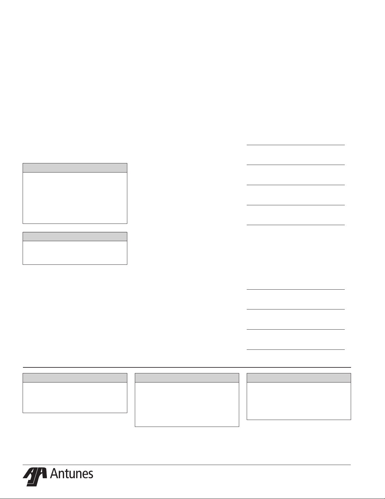
SPECIFICATIONS
A A
Model &
Mfg. No.
DMS-100
9700570
C
Width
(A)
12”
(31 cm)
B B
Depth
(B)
7”
(18 cm)
Height
(C)
14.5”
(37 cm)
Operating
Weight
16 lbs
(7.3 kg)
C
Tank Assembly
13.5”
(35 cm)
CAUTION
When installed on metallic plumb-
ing, a properly sized electrical bonding
jumper must be installed across the inlet
and outlet pipes serving this unit.
Replacement Cartridges
Replacement Part Number
Carbon Cartridge (Twin Pack) 7001197
DMS-100
Reverse Osmosis Cartridge (Single Pack) 7001198
Replacement Cartridge Kit (3 Pack) 7001201
11
(28 cm)
16”
(41 cm)
37 kg
(17 kg)
P/N 1011393 REV. A 06/164
Page 5

PERFORMANCE DATA
SHEET
Filter Cartridge Capacities
Minimum Operating
Pressure
Maximum Operating
Pressure
Minimum Operating
Temperature
Maximum Operating
Temperature
pH Range 3-10
Maximum Total Dissolved
Solids (TDS)
Maxmimum Hardness < 15 grains
Site Density Index < 5 SDI
Iron, Hydrogen Sulde, or
Manganese
Capacity 100 (GPD)
(Membrane performance after 24 hours at 77° F
(25° C), 500 ppm, TDS, and 65 psig)
NOTE: Do not use with water that is
microbiologically unsafe or
of unknown quality without
adequate disinfection before or
after the system. Systems certied for cyst reduction may be
used on disinfected waters that
may contain lterable cysts.
40 psig (276 kPa)
100 psig (690 kPa)
40° F (4° C)
100°F (38° C)
2,000 ppm
0 ppm
Performance Claims for Percent Reduction
Substance
Total Dissolved Solids
(TDS)
Minimum %
Reduction
90%
P/N 1011393 REV. A 06/16 5
Page 6
OPERATION
Overview
y Normal Operation Mode
During Normal Operation Mode, water
enters the Inlet and ows through the
Filter before exiting the outlet as usable product water.
The drain line runs continuously as
long as the system is making water.
This drain line ushes the minerals
removed by the RO membrane.
NOTE: DO NOT plug or stop the water
ow from the drain line. If this
ow is stopped, water will continued to be ltered, but the system
will not ush. This will cause the
RO membrane to plug prematurely and reduce the life of the
RO System.
y Tank Full Mode
When the tank is full, no water
runs out of the drain line.
CAUTION
Stopping the drain ow can cause the
Filter to plug prematurely and may
reduce the life of the lter. Consult
the factory for more information.
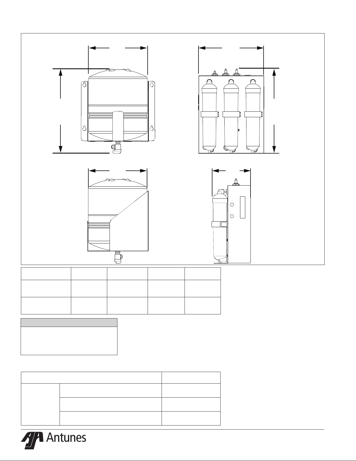
Yellow - Drain
Blue - Tank
Figure 1. Bulkhead Identication
Green - Feed Water
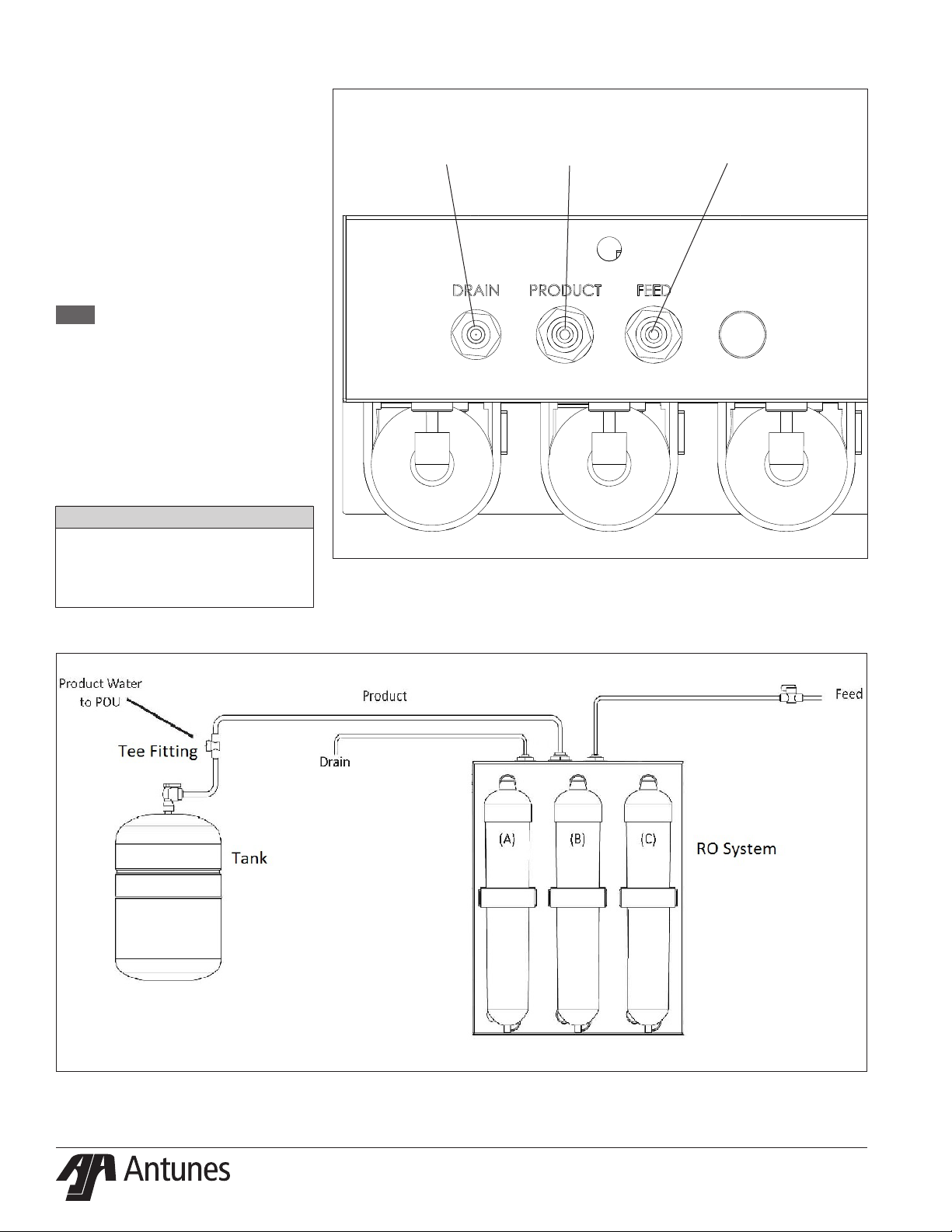
Figure 2. System Components
P/N 1011393 REV. A 06/166
Page 7

INSTALLATION
1. Open the large box. It should
contain:
a. Plate-Mounted RO System with
Cartridges installed
b. Tank Assembly with valve
attached
c. Tank Mounting Bracket
d. Owner’s Manual
e. 1 Tee Fiting, 3 Hose Barb Fittings,
and Tubing.
NOTE: If any parts are damage, contact
A.J. Antunes & Co. IMMEDIATELY
at 1-800-253-2991toll free
in the U.S and Canada or
1-630-784-1000.
2. Remove all packing materials and
protective coverings from the system
and bracket.
Equipment Setup
Plumbing
NOTE: The system must be connected to
the COLD water line. Do NOT connect the system to the hot water
line.
The RO system uses the following
connections:
Connection Description
System Inlet
System Outlet
(Product Water)
Drain
(154.4 mm)
3/8” OD Tube (1/2” ID Hose
3/8” OD Tube (1/2” ID Hose
1/4” OD Tube (1/2” ID Hose
6 in
Barb)
Barb)
Barb)
8 in
(203.2 mm)
When making a plumbing connection to
the system, use a back-up wrench on the
supporting plumbing. Always use a quality,
approved pipe sealant or thread seal tape
on pipe threads. Do NOT allow pipe sealant
inside pipes.
Do NOT over tighten the connections. Use
plastic ttings when connecting to the
plastic connections of the system.
If soldered plumbing is used, do NOT apply
heat to, or near, the ltration system. Use
union (O-ring seal) connections for ease of
installation and future servicing.
Suggested Tools and Supplies for
Installation
The following tools and supplies are suggested to help with the installation:
y Screwdriver
y Adjustable Wrenches
y Drill with Bits
y Level
y Tape Measure
y Pipe Dope or Thread Seal Tape
y Two Gallon Bucket
y Fresh, Unscented Liquid
Chlorine Bleach
y Pipe Wrenches
y Hose or pipe for drain line
12.32 in
(312.8 mm)
8 in
(203.2 mm)
CAUTION
Due to its weight and size, the Tank Assembly
MUST be mounted with the provided Mount-
ing Bracket. Read the Mounting the System
section before attempting to mount the
system. Use care when lifting heavy objects.
Mounting the System
The RO System comes with a Mounting
Bracket for the system and for the tank
When mounting the system, pay attention
to the following guidelines:
y Allow sucient access for tank
replacement and connections.
y Do not mount the system or tank
above an electrical outlet.
y Mount the system near a drain
for ushing operations.
y Mount the system after the
base ltration system and
before the equipment selected
for this water quality.
y Secure the Mounting Bracket into
wall studs or with the appropriate
heavy duty mounting hardware.
The system cover is also the system mounting plate. Refer to Figure 3. The mounting
holes are 6 inches (154.4 mm) apart. Plan
your mounting accordingly.
The tank mounting bracket has four mounting holes which are 12.32 inches (312.8 mm)
apart horizontally and 8 inches (203.2 mm)
apart vertically. The tank can be mounted
with the tank valve toward the bottom
(recommended) or towards the top.
Follow these steps to secure the RO system
and Tank Bracket to the wall (See Figure 3):
1. Secure the RO system to the wall
using the holes provided. Make sure
the mounting hardware secures the
system into wall studs or use the appropriate mounting hardware.
2. The tank Mounting Bracket is
designed so that the tank can be
mounted within 2 feet of the system
(recommended).
3. Use a stud nder and level to attach
the tank bracket to the wall with the
appropriate mounting hardware.
4. Lift the system and mount it to the
hanging hardware. Do the same
separately for the tank.
Figure 3. Mounting the System
P/N 1011393 REV. A 06/16 7
Page 8

Drain Valve Connection
The drain is for ushing particle buildup out
of the system during operation. The drain
line can be installed one of two ways:
1. Install a sucient length of 1/4” OD
tubing (not supplied) from the drain
outlet on top of the RO system to the
drain.
OR
2. Using the short length of 1/4” OD
tubing, the reducing union, and
hose barb (supplied), run a sucient
length of 1/2” ID Hose (not supplied)
from the drain outlet on top of the
RO System to the drain.
Remember to use a hose clamp (not
supplied) on the hose barb tting.
When connecting the drain hose, pay attention to the following guidelines:
y The drain line plumbing must
be able support the ow rate
when the system operates.
y The drain line leading out of
the system must be as short as
possible and slope downwards
without any kinks or loops.
y The drain line plumbing must
be positioned and secured at
least 2 inches above the drain
(Figure 4). This air gap protects
the system from contamination in
the event of a backed-up drain.
y The drain used must not be
blocked or restricted.
y The drain used must be as large or
larger than the drain line plumbing.
y The drain line from the system
should be secured at the drain using
appropriate mounting hardware.
NOTE: The drain MUST accommodate a
ow of up to 1 gpm.
Secure
End
Drain
Secure
End
Floor
Drain
Figure 4. Drain Line Plumbing
Drain Line from
System
2” (5.1 cm)
minimum
Standpipe
2” (5.1 cm)
minimum
P/N 1011393 REV. A 06/168
Page 9

Inlet Water Plumbing
Filtered water from a base ltration system
should be connected to the inlet of the RO
System.
Connect 1/2” ID Beverage hose (not supplied) to the outlet of the base ltration
system.
Before connecting to the RO System inlet,
the plumbing from the base ltration
system must be ushed clear of all debris.
Hold a bucket at the inlet water line and
slowly open the base ltration water valve.
Allow the plumbing to ush until all debris
is removed.
System Inlet Connection
The System Inlet has a 3/8” OD tube
connection at the Inlet (Figure 6). Use the
hose barb tting (supplied) and 1/2” ID
beverage hose (not supplied). Remember
to use an appropriate hose clamp (not
supplied) on the beverage tubing.
Filtered Water Permeate Outlet
Connection
The System Outlet has a 3/8” OD tube connection (Figure 6). Use the 3/8” OD tubing
(supplied) to connect between the System
outlet and the Tank inlet valve. Make sure
to install the Tee tting (supplied) in this
line between the System and the Tank. Cut
the line and install the Tee tting where
appropriate.
Yellow - Drain
Blue - Tank
Figure 5. Inlet and Outlet Connections
Green - Feed Water
P/N 1011393 REV. A 06/16 9
Figure 6. System Connections
Page 10

Rinsing the RO System
The RO System must be rinsed to remove
any air and protective solution before the
system is used.
NOTE: The RO System must be rinsed
TO DRAIN before use. Rinsing to
drain removes storage solution
and air.
1. Check that all tubing connections
are rmly seated. Check to see
that the cartridge retainer clips are
properly engaged and locked. Failure
to keep the retaining clip in place
will result in accidental leaks and
ooding.
2. Make sure the Tank valve is OPEN.
3. Turn on the water supply and check
for leaks.
4. Allow the system to run and the tank
to ll.
5. When the tank is full, the pump will
shut o. Leave the tank undisturbed
for at least 8 hours to ensure proper
sanitization.
6. Two hours after the inlet water is
turned on, check again for leaks,
especially at the tank and tubing connections leading from the
Product water outlet to the tank.
These parts will not see full pressure until 2 hours after the system is
activated.
7. After 8 hours, open the product water valve to allow the product water
in the tank to run out to drain at
maximum ow. The initial discharge
will be dark due to the bulk of the
carbon nes being washed out.
There may be the scent of chlorinated water due to the sanitizing agent
in the tank.
8. When the ow has diminished to a
fast drip, close the valve and allow
the tank to rell. The system is ready
for use.
Sanitizing the Plumbing
The plumbing from the RO System
must be sanitized to eliminate possible
contamination that may have occurred
during the installation process.
One ounce (30 ml) of liquid chlorine bleach
(regular bleach, unscented 5.25 % - 6 %
sodium hypochlorite) or Kay-5 sanitizer
solution (Sodium Dichloro-s-Triazinetrione
Dihydrate, 6%) or equivalent can be used to
sanitize the plumbing.
The Kay-5 sanitizer solution is made by
dissolving a 1 oz. packet of Kay-5 powder
in 2 oz. (60 ml) of clean warm water. This
can be done by removing 1 inch from the
top of the Kay-5 packet and adding the 2
oz. of warm water to the packet. Mix with a
coee stirrer to dissolve. When added to the
plumbing from the RO System, this will create a 60-100 ppm chlorine solution.
NOTE: Follow the handling and safety
instructions supplied with the
sanitizer.
1. Follow the steps in the Rinsing the
RO System section of this manual.
2. Turn o the water to the system.
3. Close the Tank valve.
4. Allow the system and plumbing to
drain by opening the line downstream to the RO System.
5. Disconnect the line to the equipment being served at the Tee tting
and pour the sanitizer into the line
using a cup or funnel. Be careful not
to spill the sanitizer onto clothing or
skin.
6. Reattach the line to the Tee tting.
7. Slowly turn on the Tank valve and
allow water to ow through the line
and out to the equipment.
8. Let stand without water ow for at
least 15 minutes to allow time for the
pipes to be sanitized.
9. After 15 minutes without water ow,
open the line at the equipment and
allow water and sanitizer to ow until the presence of sanitizer is gone.
10. Reconnect all lines and turn on water
to the RO. The system is now ready
for use.
P/N 1011393 REV. A 06/1610
Page 11

MAINTENANCE
Replacing the RO Cartridge
NOTE: Always install 2 new Carbon
cartridges after replacing the RO
Cartridge.
1. Turn o water to the system by clos-
ing the feed water valve.
2. Close the tank valve.
3. Open a valve on the product water
line or line to the equipment to depressurize the line. Close or reattach
when ow stops.
4. Remove the retaining clip from the
RO cartridge on the system. Pull the
cartridge o evenly at the top and
bottom. Set used cartridge aside.
NOTE: Water may drain from the system
and cartridge as it is removed.
5. Install the new cartridge by lining
up the cartridge tubes with the unit
connectors. Insert the tubes into the
connectors, rocking gently from side
to side as necessary until the cartridge tubes are properly engaged in
the unit connectors.
6. Install the retaining clip, ensuring
the slide locks snap into place in
the slots. If the clip does not snap
easily into place through the slots,
this means the cartridge is not fully
inserted into the connectors. Press
the top or bottom of the cartridge
to engage the connector so that it
snaps fully into place.
NOTE: Failure to properly install the
retaining clip will result in accidental leaks and ooding.
7. Turn on the feed water.
8. Open a valve on the product water
line or line to the equipment. Close
when water starts running out of the
line.
9. Observe the system for leaks, especially at the newly replaced cartridge.
10. Open the tank valve.
11. The system should be ushed as
described in the installation section
under RINSING THE RO SYSTEM.
12. Record the serial number of the new
cartridge and next change date.
WHITE
CONNECTOR
ON TOP
Bottom Side
Port Open
P/N 1011393 REV. A 06/16 11
Figure 8. RO Cartridge
Page 12

Replacing the Carbon Cartridges
NOTE: Always install 2 new Carbon
cartridges after replacing the
carbon.
1. Turn o the water to the system by
closing the feed water valve.
2. Close the tank valve.
3. Open a valve on the product water
line or line to the equipment to depressurize the line. Close or reattach
when ow stops.
4. Remove the retaining clip from the
cartridge on the system. Pull the
cartridge o evenly at the top and
bottom. Set used cartridge aside.
Repeat for second cartridge.
NOTE: Water may drain from the sys-
tem and cartridges as they are
removed.
5. Install the new cartridge by lining
up the cartridge tubes with the unit
connectors. Insert the tubes into the
connectors, rocking gently from side
to side as necessary until the cartridge tubes are properly engaged in
the unit connectors.
6. Install the retaining clip, ensuring
the slide locks snap into place in
the slots. If the clip does not snap
easily into place through the slots,
this means the cartridge is not fully
inserted into the connectors. Press
the top or bottom of the cartridge
to engage the connector so that it
snaps fully into place.
NOTE: Failure to properly install the
retaining clip will result in accidental leaks and ooding.
7. Install the second cartridge accord-
ing to steps 5 and 6.
8. Turn on the feed water.
9. Open a valve on the product water
line or line to the equipment. Close
when water starts running out of the
line.
10. Observe the system for leaks, especially at newly replace cartridge.
11. Open the tank valve.
12. The system should be ushed as
described in the installation section
under RINSING THE RO SYSTEM.
13. Record the serial number of the new
cartridges and next change date.
Sanitization
The downstream plumbing should be
sanitized every six months. When necessary, follow the SANITIZING THE PLUMBING
procedure in the Installation section of this
manual.
GREEN
CONNECTOR
ON TOP
Bottom Side
Port Blocked
Figure 9. Carbon Cartridge
P/N 1011393 REV. A 06/1612
Page 13

Initial Performance Verication
After initial ush, a TDS (Total Dissolved
Solids) measurement should be taken and
recorded. This data can be used to compare
to factory test data and future system data.
Some deviations may occur due to dierences in feed water TDS and temperature
Total Dissolved Solids ( TDS) Rejection Test
USe a TDS meter to measure the TDS in both
the feed water and product water. Calculate
the percent rejection using the formula
below. Rejection should be 85% or better:
100 x (Feed TDS - Product TDS) / (Feed
TDS) = % Rejection
Example:
Feed TDS = 500 ppm
Product TDS = 25 ppm
100 x (500 - 25) / (500) = 95% Rejection
RO Recovery Calculation
Using a stop watch and graduated cylinder
(or other calibrated volume), measure the
product water ow rate and the drain ow
rate. The product water ow rate should
be the ow coming directly from the RO
System, not from the tank. Close the tank
valve to make this measurement. Calculate
the percent recovery using the formula
below:
100 x (Product Flow Rate) / (Product +
Drain) = % Recovery
Example:
Product Flow Rate = 25 mil/min
Drain Flow Rate = 200 ml/min
100 x (25) / (25 + 200 ) = 11.1%
Recovery
Recovery is dependent on feed water temperature and pressure. Measure and record
the feed water temperature and pressure
whenever measuring the percent recovery.
Tank Pressure Switch Test
With the product water line connected to
the tank and with the system running, close
the tank valve. The pressure in the line from
the system will rise and the system should
shut o (drain ow stops).
Opening the tank valve allows the pressure
to drop in the line from the system and the
system should turn on.
SEMIANNUAL TASKS
Check Permeate Tank Air
Pre-Charge
The permeate tank air charge should be
checked every six months:
Tools and supplies required:
Air Pressure Gauge, 5-40 psi range (0.3 -
2.7 bar) with tire valve (Schrader Valve)
connection.
Source of compressed air (manual bicycle
tire pump or air compressor).
CAUTION
Air pre-charge should be checked and adjust-
ed under zero system pressure. The system
must be depressurized before checking the
tank pre-charge. Do NOT adjust the tank air
pre-charge with the system under pressure.
CAUTION
Be careful when adding air to the tank. Do
NOT add too much air pressure to the tank.
1. Refer to Figure 1. Depressurize the
system by closing the Inlet valve and
opening the Tank valve. Make sure
the Permeate Tank is fully drained.
2. Unscrew the protective cap from the
air valve on the tank.
3. Use the pressure gauge to check the
tank pre-charge for pressure.
NOTE: If any water comes out of the
air valve, the tank bladder has
ruptured and the tank needs to
be replaced.
4. The permeate tank should have a
pressure of 5-8 psi.
y To add pressure to the permeate
tank, use a manual bicycle tire pump
or other source of compressed air.
y To release pressure from the
permeate tank, press the center
pin on the air inlet valve.
5. Once the permeate tank is at 5-8 psi,
replace the protective cap on the air
valve.
6. Pressurize the system by opening
the Inlet and Tank valves.
ANNUAL TASK
Change Carbon and RO
Cartridges
Both the Carbon Cartridges and the RO Cartridge
should be changed once a year.
Follow the change procedures for each as shown
earlier in this Maintenance section.
P/N 1011393 REV. A 06/16 13
Page 14

TROUBLESHOOTING
Problem Possible Cause Corrective Action
Inlet/Outlet valves closed. Open the inlet/Outlet valves.
System depressurized. Pressurize system.
No water comes out of the lter
system.
Low water ow comes out of
the lter system.
Water tastes bad.
Flush runs continuously. Tank pressure switch stuck open. Replace tank pressure switch.
Permeate pump not working. Replace permeate pump.
Inlet Strainer (if installed) is plugged. Clean or replace Inlet Strainer.
RO Cartridge is plugged. Replace RO Cartridge.
Carbon Cartridges are plugged. Replace carbon cartridges.
See Above. See Above.
The inlet water pressure is too low. Boost the inlet water pressure.
Tank air charge low. Add air to tank.
Tank diaphragm ruptured, waterlogged. Replace tank.
Carbon cartridges need replacing. Replace carbon cartridges.
Storage/shipping solution not completely rinsed out of
the system.
Biological growth in pipes. Sanitize plumbing.
Water conditions changed. Consider installing additional ltration.
Broken membrane in RO Cartridge. Replace RO Cartridge.
Rinse the system for a longer period of time; replace
carbon cartridges.
Water splashes at drain during
ush.
Water leaks at ends of the
Filter cartridge after changing
cartridge.
Water leaks from system tting
or connection
Drain line not positioned properly. Reposition the end of the drain line.
Drain not capable of handling ow rate. Clean drain; nd alternate drain.
Fitting o-ring not lubricated or cut. Replace tting.
Cartridge not seated properly in tting. Re-install cartridge in ttings.
Fitting broken or loose. Tighten or replace the tting.
P/N 1011393 REV. A 06/1614
Page 15

REPLACEMENT PARTS
2
8
4
3
5
6
7
Replacement Parts can be purchased from an authorized dealer. Contact
A.J. Antunes & Co. at 1-630-754-1000 or toll free in the United States at 1-800-253-2991.
Item Part # Description Qt y.
1 7001197 Replacement Carbon Kit,
Twin Pack
7001198 Replacement RO Kit,
Single Pack
7001201 Replacement Cartridge
Kit, Triple Pack (incl.
7001197 and 7001198)
2 7001200 Tank assembly w/ valve 1
3 2080157 Product water Tee Fitting 1
4 2080155 Adapters, 3/8” OD x 1/2”
Hose Barb
5 2080129 Reducing Union, 3/8” OD
Tube x 1/4” OD Tube
6 5206015 Tubing 3/8” OD 2 ft.
1
1
1
4
1
1
7 5206017 Tubing, 1/4” OD 1 ft.
8 0507649 RO Tank Bracket 1
9 7001199 Replacement Permeate
Pump Kit (not shown)
1
P/N 1011393 REV. A 06/16 15
Page 16

Date
Feed
Temperature
(°F)
Feed
Pressure
(psig)
Product
Flowrate
(ml/min)
Drain
Flowrate
(ml/min)
Percent
Recovery
(%)
Product
TDS
(ppm)
Feed
TES
(ppm)
Percent
Rejection
(%)
P/N 1011393 REV. A 06/1616
Page 17

Changed
Carbons
Next Carbons
Change
Date Date
Changed
RO
Next RO
Change
Changed
Carbons
Next Carbons
Change
Changed
RO
Next RO
Change
P/N 1011393 REV. A 06/16 17
Page 18

NOTES
P/N 1011393 REV. A 06/1618
Page 19

NOTES
P/N 1011393 REV. A 06/16 19
Page 20

LIMITED WARRANTY
Equipment manufactured by A.J. Antunes & Co. has been constructed of the finest materials available and manufactured to high quality standards. These units are warranted to be free from defects in materials and workmanship for a period of two years from date of
purchase under normal use and service, and when installed in accordance with manufacturer’s recommendations*. The ultra filtration
membrane cartridge is warranted under the same terms and conditions on a prorated basis for 36 months from date of purchase.
*To ensure continued proper operation of the units, follow the maintenance procedure outlined in the Owner’s Manual.
1. This warranty does not cover failures due to improper system installation, defects caused by improper storage or handling prior
to placing of the equipment into service. This warranty does not include overtime charges or work done by unauthorized service
agencies or personnel. This warranty does not cover normal maintenance, calibration, or regular adjustments as specified in
operating and maintenance instructions of this manual, and/or labor involved in moving adjacent objects to gain access to the
Equipment.
2. A.J. Antunes & Co. reserves the right to make changes in design or add any improvements on any product. The right is always
reserved to modify equipment because of factors beyond our control and government regulations. Changes to update equipment do not constitute a warranty charge.
3. If shipment is damaged in transit, the purchaser should make a claim directly upon the carrier. Careful inspection should be
made of the shipment as soon as it arrives and visible damage should be noted upon the carrier’s documentation. Damage
should be reported to the carrier. This damage is not covered under this warranty.
4. THIS WARRANTY IS EXCLUSIVE AND IS IN LIEU OF ALL OTHER WARRANTIES, EXPRESSED OR IMPLIED, INCLUDING
ANY IMPLIED WARRANTY OR MERCHANTABILITY OR FITNESS FOR A PARTICULAR PURPOSE, EACH OF WHICH IS
HEREBY EXPRESSLY DISCLAIMED. THE REMEDIES DESCRIBED ABOVE ARE EXCLUSIVE AND IN NO EVENT SHALL
A.J. ANTUNES & CO. BE LIABLE FOR SPECIAL CONSEQUENTIAL OR INCIDENTAL DAMAGES FOR THE BREACH OR
DELAY IN PERFORMANCE OF THIS WARRANTY.
Prices and specications are subject to change without notice.
 Loading...