

Page 1
Heated Display
Cabinet
Models DCH-500, DCH-800, & DCH-1000
owner’s manual
Manufacturing Numbers:
9500640, 9500650 & 9500720
www.antunes.com
P/N 1011306 Rev. D 12/17
Page 2
CONTENTS
General 2
Warranty
Information 2
Service/Technical
Assistance 2
Important Safety
Information 3
Warnings 3
Specications 4
Dimensions 4
Electrical Ratings 4
Installation 5
Unpacking 5
Equipment Setup 5
Operations and Programming 6
Maintenance 6
Daily Cleaning 6
Display Codes 7
Troubleshooting 8
Replacement Parts DCH-500 9
Replacement Parts DCH-800 11
Replacement Parts DCH-1000 13
Notes 15
IMPORTANT
A.J. Antunes & Co. reserves the right to
change specications and product de-
sign without notice. Such revisions do not
entitle the buyer to corresponding changes,
improvements, additions or replacements
for previously purchased equipment.
GENERAL
This manual provides the safety, installation,
and operating procedures for your toaster.
Please read all of the information contained
in this manual prior to installing and operating the toaster.
This product is manufactured from the
nest materials available and is assembled
to Roundup’s strict quality standards. This
toaster was tested at the factory to ensure
dependable trouble-free operation.
WARRANTY
INFORMATION
Please read the full text of the Limited
Warranty in this manual.
If the unit arrives damaged, contact the
carrier immediately and le a damage claim
with them. Save all packing materials when
ling a claim. Freight damage claims are the
responsibility of the purchaser and are not
covered under warranty.
The warranty does not extend to:
y Damages caused in shipment or
damage as result of improper use.
y Installation of electrical service.
y Normal maintenance as
outlined in this manual.
y Malfunction resulting from
improper maintenance.
y Damage caused by abuse
or careless handling.
y Damage from moisture into
electrical components.
y Damage from tampering with,
removal of, or changing any
preset control or safety device.
SERVICE/TECHNICAL
ASSISTANCE
If you experience any problems with the
installation or operation of your system,
contact Antunes at 1-630-784-1000, or toll
free in the United States at 1-800-253-2991.
Fill in the information in the next column and have it handy when calling for
assistance. The serial number is on the
specication plate located on the system.
Purchased From
Date of Purchase
Model Number
Serial Number
Mfg. Number
Use only genuine Antunes replacement
parts in this unit. Use of replacement parts
other than those supplied by the manufacturer will void the warranty. Your Authorized
Service Agency has been factory trained
and has a complete supply of parts for this
unit.
IMPORTANT
Keep these instructions for future refer-
ence. If the unit changes ownership, be sure
this manual accompanies the equipment.
P/N 1011306 Rev. D 12/172
Page 3

IMPORTANT SAFETY
INFORMATION
Use the following guidelines for safe operation of the unit.
y Read all instructions before
using equipment.
y For your safety, the equipment is
furnished with a properly grounded
cord connector. Do not attempt to
defeat the grounded connector.
y Install or locate the equipment only
for its intended use as described in
this manual. Do not use corrosive
chemicals in this equipment.
y Do not operate this equipment if
it has a damaged cord or plug, if
it is not working properly, or if it
has been damaged or dropped.
y This equipment should be serviced
by qualied personnel only. Contact
your nearest Authorized Service
Agency for adjustment or repair.
y Do not block or cover any
openings on the unit.
y Do not immerse cord or plug in water.
y Keep cord away from heated surfaces.
y Do not allow cord to hang over
edge of table or counter.
y Turn the power o, unplug the
power cord, and allow unit to cool
down before performing any service
or maintenance on the unit.
y The equipment should be grounded
according to local electrical codes to
prevent the possibility of electrical
shock. It requires a grounded
receptacle with separate electrical
lines, protected by fuses or circuit
breaker of the proper rating.
y All electrical connections must be in
accordance with local electrical codes
and any other applicable codes.
y Do not clean this appliance
with a water jet.
WARNINGS
Be advised of the following warnings when
operating and performing maintenance on
this unit.
y If the supply cord is damaged,
it must be replaced by the
manufacturer or its service agent
or a similarly qualied person
in order to avoid a hazard.
y Do not modify the power supply
cord plug. If it does not t the
outlet, have a proper outlet
installed by a qualied electrician.
y Do not use an extension
cord with this appliance.
y Electrical ground is required
on this appliance.
y Check with a qualied electrician
if you are unsure if the appliance
is properly grounded.
y If a chemical cleaner is used,
be sure it is safe to use on cast
aluminum. Observe all precautions
and warnings on product label.
y Inspection, testing, and
repair of electrical equipment
should only be performed by
qualied service personnel.
y Do not use abrasive materials. The
use of these may cause damage
to the stainless steel nish.
y Chlorides or phosphates in cleaning
agents (e.g. bleach, sanitizers,
degreasers or detergents) could cause
permanent damage to stainless steel
equipment. The damage is usually in
the form of discoloration, dulling of
metal surface nish, pits, voids, holes,
or cracks. This damage is permanent
and not covered by warranty.
The following tips are recommended
for maintenance of your stainless steel
equipment:
y Always use soft, damp cloth for
cleaning, rinse with clear water and
wipe dry. When required, always rub
in direction of metal polish lines.
y Routine cleaning should be
done daily with soap, ammonia
detergent, and water.
y Stains and spots should be sponged
using a vinegar solution.
y Finger marks and smears should be
rubbed o using soap and water.
y Hard water spots should be
removed using a vinegar solution.
P/N 1011306 Rev. D 12/17 3
Page 4
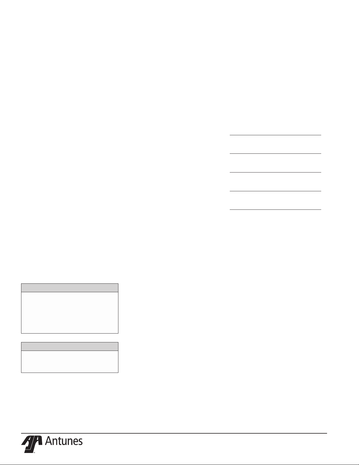
SPECIFICATIONS
Dimensions
A
B
C
Model &
Mfg. No.
DCH-500
9500720
DCH-800
9500650
DCH-1000
9500640
Model &
Mfg. No.
DCH-500
9500720
DCH-800
9500650
DCH-1000
9500640
A
Height
28”
(711 mm)
28”
(711 mm)
28”
(711 mm)
B
Width
23.75”
(603.25 mm)
37.75”
(958.8 mm)
47.75”
(1212.8 mm)
C
Depth
25”
(635 mm)
25”
(635 mm)
25”
(635 mm)
Electrical Ratings
Volts Watts Amps Hertz
120 500 4.16 50/60
120 800 6.6 50/60
120 1000 8.3 50/60
Plug
Description
NEMA 5-15P, 15 Amp.,
120 Volt
P/N 1011306 Rev. D 12/174
Page 5
INSTALLATION
Unpacking
1. Remove unit and all packing materi-
als from shipping carton.
2. Open the large box. Remove all
packing materials and protective
coverings from the unit and parts.
NOTE: If any parts are missing or dam-
aged, contact A.J. Antunes & Co.
IMMEDIATELY at 1-800-253-2991
(toll free in the U.S. and Canada)
or at 630-784-1000.
3. Clean all glass components with
an approved glass cleaner. Wipe all
stainless steel areas of the unit with a
hot damp cloth.
NOTE: Do NOT use a dripping wet cloth.
Wring out before use.
4. Place the unit where required.
Equipment Setup
When placing the unit into service, pay attention to the following guidelines.
y Make sure power is o and the
unit is at room temperature.
y Do NOT block or cover any
openings on the unit.
y Do NOT immerse cord
or plug in water.
y Keep cord away from heated surfaces.
y Do NOT allow cord to hang over
edge of table or counter.
y Place unit on a sturdy, level
table or work surface.
Ensure that the line voltage corresponds to
the stated voltage on the unit specication
label.
Ensure the power to the unit is turned o
before plugging in the power cord.
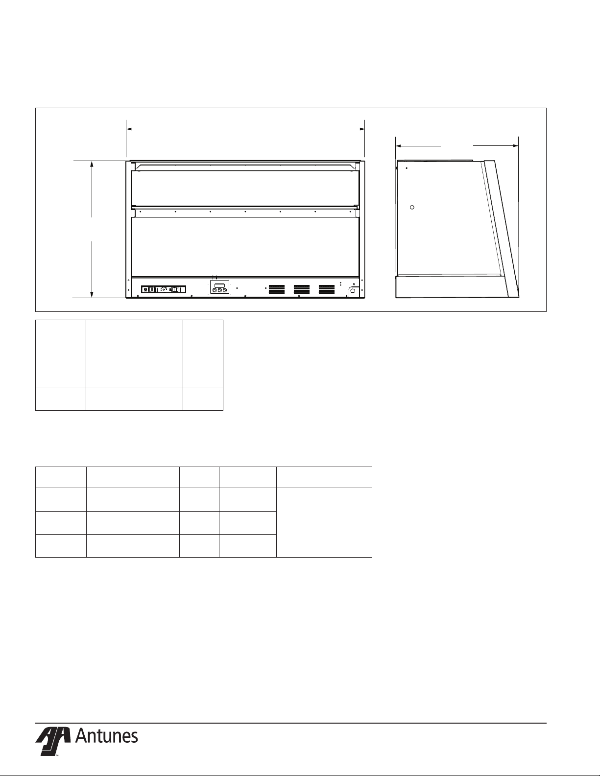
Shelf
Anchor
LED Lights
(also secures
Glass Shelf)
Shelf
Anchor
Glass
Shelf
Figure 1. DCH-1000 Components
CAUTION
All electrical connections must be in
accordance with local electrical codes
and any other applicable codes.
WARNING
y ELECTRICAL SHOCK HAZARD.
Failure to follow the instructions
in this manual could result
in serious injury or death.
y Electrical ground is required
on this appliance.
y Do NOT modify the power supply
cord plug. If it does not t the
outlet, have a proper outlet
installed by a qualied electrician.
y Do NOT use an extension
cord with this unit.
y The unit should be grounded
according to local electrical
codes to prevent the possibility
of electrical shock. It requires
a grounded receptacle with
separate electrical lines,
protected by fuses or circuit
breaker of the proper rating.
y Check with a qualied electrician
if you are unsure if the appliance
is properly grounded.
Front
of Unit
Light Power & Dimmer
Heat Power
Control
Panel
Rear
of Unit
Power
Cord
P/N 1011306 Rev. D 12/17 5
Page 6
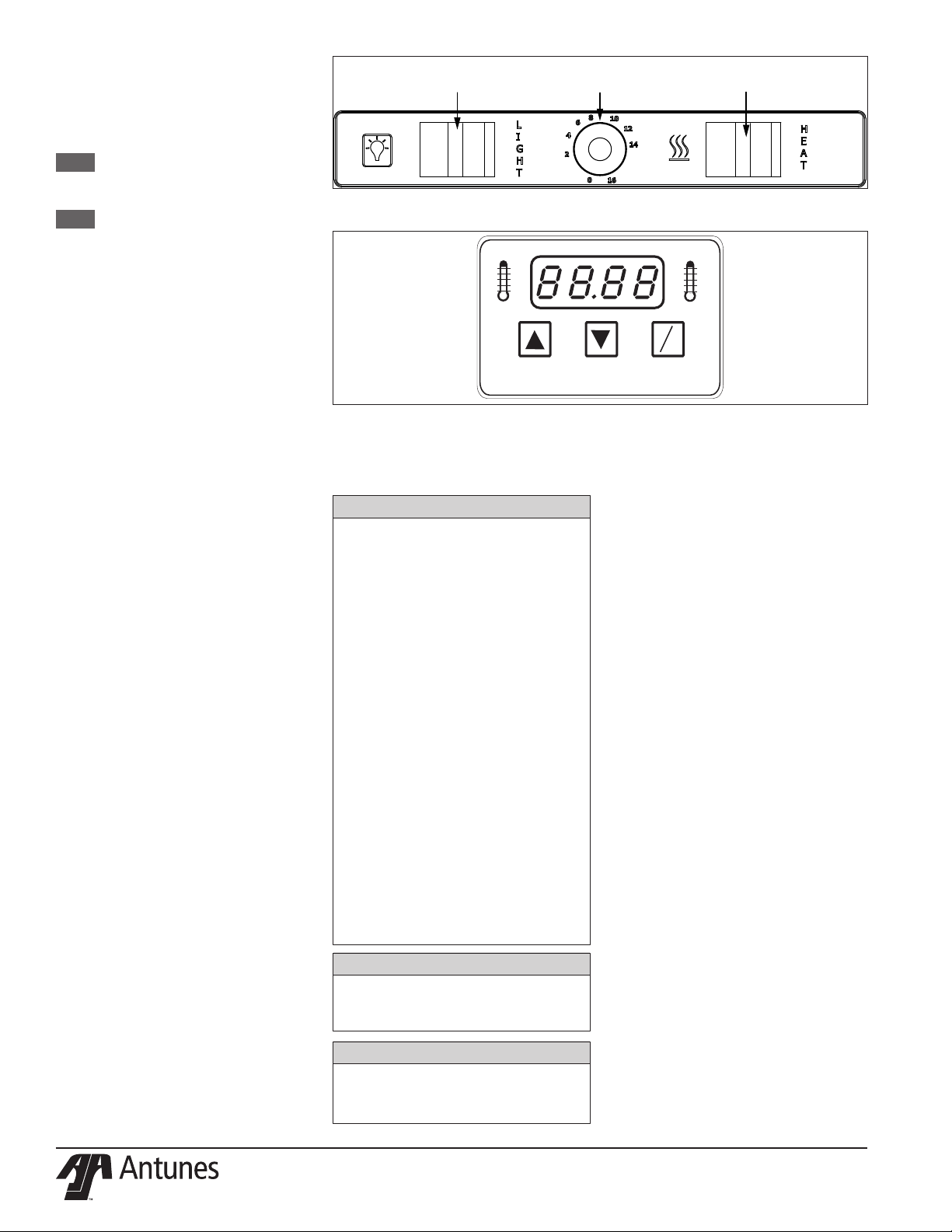
OPERATIONS AND
PROGRAMMING
The DCH-800 andDCH-1000 is designed to
temporarily slow the cooling of food.
NOTE: This unit has an adjustable
temperature range of 150-165° F
(66-74° C).
NOTE: The Setpoint temperature is
the desired cabinet temperature setting. When the Temp
UP button is pressed and held
(and provided that the unit is
up to temperature), the actual
cabinet temperature is displayed.
When the button is released,
the Setpoint temperature is
displayed.
1. Turn the Heat rocker switch ON
(Figure 2). The display ashes “LO” to
indicate that the unit is heating up.
After 20-30 minutes (when the unit
is up to temperature), the display will
show the setpoint temperature.
2. Turn the Light rocker switch to turn
on the LED lights and illuminate
product. Use the Light Dimmer Knob
to adjust the brightness of the lights.
1 is the lowest setting and 10 is the
highest setting.
3. To adjust the setpoint temperature, press and hold the Temp Up
and Temp Down buttons until the
display begins to ash. Release the
buttons. Then, press the Temp Up
or Temp Down buttons to raise or
lower the setpoint temperature.
Release when the display shows the
desired temperature.
4. To change the display from
Fahrenheit to Celsius and back,
press and hold the Temp Scale but-
ton (Figure 3) for 2-3 seconds and
release.
5. Load product into the display.
Light
Rocker Switch
Figure 2. DCH-1000 Turning on Heat and Lights
TEMP
UP
Figure 2. DCH-1000 Control Panel
MAINTENANCE
CAUTION
Chlorides or phosphates in cleaning agents
(e.g. bleach, degreasers or detergents)
could cause permanent damage to stain-
less steel equipment. The damage is
usually in the form of discoloration, dulling
of metal surface nish, pits, voids, holes
or cracks. This damage is permanent and
NOT covered by warranty. The following
tips are recommended for maintenance
of your stainless steel equipment:
y Always use soft, damp cloth
for cleaning, rinse with clear
water and wipe dry. When
required, always rub in direction
of metal polish lines.
y Routine cleaning should be
done daily using soap, ammonia
detergent and water.
y Stains and spots should be
removed using a vinegar solution.
y Finger marks and smears should
be removed using soap and water.
y Hard water spots should be
removed using a vinegar solution.
Light
Dimmer Knob
TEMP
DOWN
Daily Cleaning
The unit requires a minimum amount of
maintenance. To ensure proper operation,
clean the unit at the end of each serving
day.
1. Turn both the Light and Heat rocker
2. Unplug the power cord from the
3. Remove any product tray and wash
4. Clean glass surfaces, inside and out,
5. Wipe all non-glass surfaces of the
Heat
Rocker Switch
O
F
O
C
TEMP
SCALE
switches to the o position.
electrical outlet and allow the unit
to cool to room temperature before
proceeding.
in soap and water. Then rinse and
wipe dry.
with an approved glass cleaner.
unit with a clean damp towel and
allow to air dry.
WARNING
Turn the power o, unplug the power cord,
and allow the unit to cool down before
performing any service or maintenance.
WARNING
Do NOT use abrasive cleansers or ma-
terials. The use of these may cause
damage to the stainless steel nish.
P/N 1011306 Rev. D 12/176
Page 7

Display Codes
TEMP
UP
TEMP
DOWN
TEMP
SCALE
F
C
O
O
This section describes the dierent display codes and their
meanings.
“LO” ashes during the initial warm up period. The unit continues
to display this code until the unit reaches the setpoint temperature. When the unit reaches the setpoint temperature, it displays
the setpoint temperature.
This gure shows an example setpoint temperature of 150° F
displayed on the console.
“HI” ashes if the actual cabinet temperature exceeds the setpoint
temperature or if the thermistor has shorted.
NOTE: The thermistor should be 100k ohm +/- 2% at room
temperature.
P/N 1011306 Rev. D 12/17 7
“OPEN” ashes if the thermistor is OPEN or disconnected. The unit
will not call for heat.
NOTE: The thermistor should be 100k ohms +/- 2% at room
temperature.
“PO” In 120 VAC units, this code ashes if the supply voltage is
below 100 VAC or above 135 VAC. In 220/240 VAC units, this code
ashes if the supply voltage is below 190 VAC or above 265 VAC.
NOTE: If voltage is within normal ranges, then the
Control Board is faulty.
To reset a unit in this state, the supply voltage must be within acceptable limits and the unit must be turned o for a few seconds
and then turned back on.
Page 8

TROUBLESHOOTING
WARNING
To avoid possible personal injury and/or damage to the unit, inspection, test and repair of electrical equip-
ment should be performed by qualied service personnel. The unit should be unplugged when servicing.
Problem Possible Cause Corrective Action
No heat, no display, and the power
switch indicator light is OFF.
No heat, no display, and the power
switch indicator light is ON.
Display ashes “LO” and the cabinet
does not heat up.
Display ashes “HI” and the cabinet
does not heat up.
Display ashes “HI” and the cabinet
is very hot.
Display ashes “OPEN” and the
cabinet does not heat up.
Display ashes “PO” and the cabinet does not heat up.
Product dries out quickly. Setpoint temperature is set too high. Lower the Setpoint temperature.
LED lights do not light up. LED Strip is damaged. Contact your maintenance person or Authorized Service Agency
Power cord is not plugged in. Plug the power cord into the appropriate outlet.
Circuit breaker is o or has been tripped. Reset circuit breaker, contact your maintenance person or
No power at receptacle. Contact your maintenance person or Authorized Service Agency
Inoperable power cord.
Inoperable power switch.
Loose, burnt, broken wiring in the circuit.
Inoperable Transformer. Contact your maintenance person or Authorized Service agency
Inoperable Control Board.
Loose, burnt, broken wiring in circuit.
Inoperable Solid State Relay. Contact your maintenance person or Authorized Service Agency
Inoperable Control Board.
Inoperable Heater(s).
Loose, burnt, broken wiring in circuit.
Inoperable Thermistor. Contact your maintenance person or Authorized Service Agency
Inoperable control Board.
Solid State Relay contacts shorted closed. Contact your maintenance person or Authorized Service Agency
Inoperable Control Board.
Thermistor is disconnected or open. Re-secure the Thermistor onto the Control Board. If this prob-
Inoperable Control Board.
For 120 volt units, the supply voltage is below 100
VAC or above 135 VAC.
Inoperable Control Board.
Loose, burnt, or broken wiring in Circuit.
Authorized Service Agency if it trips again.
for service.
for service.
for service.
for service.
for service.
lem persists, contact your maintenance person or Authorized
Service Agency for service.
Contact your maintenance person or Authorized Service Agency
for service.
for service.
P/N 1011306 Rev. D 12/178
Page 9

REPLACEMENT PARTS DCH500 SHEET 1
Item Part No. Description Qty.
1 7001773 Top Glass 24 1
2 7001713 Front Glass Kit 1
3 0900320 Front Glass 1
4 5040282 Rail 48.68 LG 1
5 7001732 Glass Shelf Kit, 24” 1
6 7001380 Side Glass Kit, 0900319 2
7 2000253 Glass Shelf Mounting Hdwe 2
8 7001435 Glass Shelf Support Kit 2
9 7001438 Corner Bracket 2
10 215P410 Spacer 1
11 325P207 Washer 1
12 210P360 Thumb Screw 1
13 215P152 Nylon Push in Bearing 1
*Available in packages of ten
P/N 1011306 Rev. D 12/17 9
Page 10

REPLACEMENT PARTS DCH500 SHEET 2
Item Part No. Description Qty.
1 7001717 Heat Plate Kit, 24” 1
4 308P157* Scr,Tap #08-32 X 3/8 Phtrshd;”F”;410 S/S 1
5 1001037 Label, Control Panel 1
6 1001602 Label, SW1 1
6A 1001603 Label, SW2 1
7 304P105* Nut,Hex’keps’#4-40 Zinc 1
8 306P101* Nut,Hex #06-32 St.stl. 1
9 306P121* Scr,Mach #06-32 X 3/4 Slrndhd;
Steel;Zinc Pl. 1
10 308P124* Scr,Mach #8-32 X 1/2” 1-Wayhd;18-8 S/S 1
11 308P143* Nut,Hex”Keps” #08-32 Steel; Zinc Plated 1
12 308P157* Scr,Tap #08-32 X 3/8 Phtrshd;”F”;410 S/S 1
13 7001580 Power Switch Replacement 2
14 7001720 Thermostat, Hi Limit Kit 1
15 7001478 Terminal Block Kit 1
16 0013258 Control Panel Assembly 1
Item Part No. Description Qty.
17 0022270 Heat Sink Weldment 1
20 7001148 Transformer, 120 VAC/12VAC 1
21 7000370 Solid State Relay Kit 1
22 0400251 Strain Relief 1
23 0700463 Power Cord 1
24 7001718 Power Supply Kit 1
25 308P203* Screw #8-32 X 3/8 With Int. Tooth Washer 1
26 308P199* Nut, Hex Keps #8-32 S/S (Cti) Ifn00374 1
27 0022252 Control Panel Weldment 1
28 0400138 Nut, Lock Conduit 1/2” 1
29 0507070 Thermo Bracket 1
30 308P143* Nut,Hex”Keps” #08-32 Steel; Zinc Plated 1
31 7001456 24” Light Bar Kit 1
33 7000345 Control Board Kit 1
-- 7001719 Cable, DC Plug Kit 1
-- 7000369 Thermistor Replacement Kit 1
*Available in packages of ten
P/N 1011306 Rev. D 12/1710
Page 11

REPLACEMENT PARTS DCH800 SHEET 1
12
11
12
7
13
11
6
10
8
9
1
12
48
9
10
8
5
6
11
12
7
13
11
3
10
2
4
Item Part No. Description Qty.
1 7001714 Top Glass Kit 36” 1
3 0900326 Front Glass Assy 1
4 5040284 36 Frame Hinge 1
5 Middle Shelf - waiting on kit 1
6 7001380 Side Glass Kit, 0900319 2
7 7001435 Glass Shelf Support Kit 2
9 7001438 Corner Bracket 2
10 215P410 Spacer 1
11 325P207 Washer 1
12 210P360 Thumb Screw 1
13 215P152 Nylon Push in Bearing 1
*Available in packages of ten
P/N 1011306 Rev. D 12/17 11
Page 12

REPLACEMENT PARTS DCH800 SHEET 2
31
29
1
25
13
13
2
14
17
6
20
5
32
31
7
26
21
72
24
8
11
15
9
10
12
27
Item Part No. Description Qty.
1 7001721 Heater Plate Kit 1
2 0013161 Heater Assembly 1
4 308P203* Scr,Tap #8-32 X 3/8 W Int. Tooth Washer 1
5 1001037 Label, Control Panel 1
6 1001597 Label, Control 1
7 306P130* Nut,Hex’keps’ #6-32 Small Pattern 1
8 306P101* Nut,Hex #06-32 St.stl. 1
9 306P121* Scr,Mach #06-32 X 3/4 Slrndhd;
Steel;Zinc Pl. 1
10 308P124* Scr,Mach #8-32 X 1/2” 1-Wayhd;18-8 S/S 1
11 308P143* Nut,Hex”Keps” #08-32 Steel; Zinc Plated 1
12 308P157* Scr,Tap #08-32 X 3/8 Phtrshd;”F”;410 S/S 1
13 7001580 Power Switch Replacement Kit 2
14 7001720 Thermostat, Hi-Limit Kit 1
15 7001478 Terminal Block Kit 1
Item Part No. Description Qty.
16 7000345 Control Board Kit 1
17 0022132 Heat Sink Bracket Weldment 1
20 7001148 Transformer, 120 VAC, 12 VAC 1
21 7000370 Solid State Relay Kit 1
22 0400251 Strain Relief 1
23 0700463 Power Cord 1
24 7001718 Power Supply Kit 1
25 308P203* Screw #8-32 X 3/8 With Int. Tooth Washer 1
26 308P199* Nut, Hex Keps #8-32 S/S (Cti) Ifn00374 1
27 0022097 Control Panel Weldment 1
28 0400138 Nut, Lock Conduit 1/2” 1
29 0507070 Thermo Bracket 1
30 308P143* Nut,Hex”Keps” #08-32 Steel; Zinc Plated 1
31 7001455 36” Light Bar Kit 1
-- 7001719 Cable, DC Plug Kit 1
-- 7000369 Thermistor Replacement Kit 1
*Available in packages of ten
P/N 1011306 Rev. D 12/1712
Page 13

REPLACEMENT PARTS DCH1000 SHEET 1
3
2
4
1
5
874
6
9
Item Part No. Description Qty.
1 7001715 Top Glass Kit, 48 1
2 7001869 Front Glass kit 1
3 0900320 Front Glass 1
4 5040282 Rail 48.68 LG 1
5 7001870 Glass Shelf Kit 1
6 7001380 Side Glass Kit, 0900319 2
7 7001435 Glass Shelf Support Kit 2
8 7001438 Corner Bracket 2
9 210P360 Thumb Screw 1
P/N 1011306 Rev. D 12/17 13
Page 14

7
162427
14
20
28
26
21
136131222
2
5
8
11
231510
9
4
25
30
29
1
25
7
162427
14
20
28
26
21
136131222
2
5
8
11
231510
9
4
25
30
29
1
25
32
31
31
REPLACEMENT PARTS DCH1000 SHEET 2
Item Part No. Description Qty.
1 7001868 Heater Plate Kit 1
4 308P157* Scr,Tap #08-32 X 3/8 Phtrshd;”F”;410 S/S 1
5 1001037 Label, Control Panel 1
6 1001593 Label, Control 1
7 304P105* Nut,Hex’keps’#4-40 Zinc 1
8 306P101* Nut,Hex #06-32 St.stl. 1
9 306P121* Scr,Mach #06-32 X 3/4 Slrndhd;
Steel;Zinc Pl. 1
10 308P124* Scr,Mach #8-32 X 1/2” 1-Wayhd;18-8 S/S 1
11 308P143* Nut,Hex”Keps” #08-32 Steel; Zinc Plated 1
12 308P157* Scr,Tap #08-32 X 3/8 Phtrshd;”F”;410 S/S 1
13 7001580 Power Switch Replacement 2
14 7001720 Thermostat, Hi Limit Kit 1
15 7001478 Terminal Block Kit 1
16 7000345 Control Board Kit 1
Item Part No. Description Qty.
17 0022132 Heat Sink Weldment 1
20 7001148 Transformer, 120VAC/12VAC 1
21 7000370 Solid State Relay Kit 1
22 0400251 Strain Relief 1
23 0700463 Power Cord 1
24 7001718 Power Supply Kit 1
25 308P203* Screw #8-32 X 3/8 With Int. Tooth Washer 1
26 308P199* Nut, Hex Keps #8-32 S/S (Cti) Ifn00374 1
27 0022097 Control Panel Weldment 1
28 0400138 Nut, Lock Conduit 1/2” 1
29 0507070 Thermo Bracket 1
30 308P143* Nut,Hex”Keps” #08-32 Steel; Zinc Plated 1
31 7001716 Light Bar Kit, 48” 1
-- 7000369 Thermistor Replacement Kit 1
-- 7001719 Cable, DC Plug Kit 1
*Available in packages of ten
P/N 1011306 Rev. D 12/1714
Page 15

NOTES
P/N 1011306 Rev. D 12/17 15
Page 16

P/N 1011306 Rev. D 12/1716
Page 17

LIMITED WARRANTY
Equipment manufactured by Roundup Food Equipment Division of A.J. Antunes & Co. has been constructed of the nest
materials available and manufactured to high quality standards. These units are warranted to be free from electrical and
mechanical defects for a period of one (1) year from date of purchase under normal use and service, and when installed in
accordance with manufacturer’s recommendations. To insure continued operation of the units, follow the maintenance
procedures outlined in the Owner’s Manual. During the rst 12 months, electro-mechanical parts, non-overtime labor,
and travel expenses up to 2 hours (100 miles/160 km), round trip from the nearest Authorized Service Center are covered.
1. This warranty does not cover cost of installation, defects caused by improper storage or handling prior to placing
of the Equipment. This warranty does not cover overtime charges or work done by unauthorized service agencies
or personnel. This warranty does not cover normal maintenance, calibration, or regular adjustments as specied
in operating and maintenance instructions of this manual, and/or labor involved in moving adjacent objects to
gain access to the equipment. This warranty does not cover consumable/wear items. This warranty does not cover
damage to the Load Cell or Load Cell Assembly due to abuse, misuse, dropping of unit/shock loads or exceeding
maximum weight capacity (4 lbs). This warranty does not cover water contamination problems such as foreign
material in water lines or inside solenoid valves. It does not cover water pressure problems or failures resulting
from improper/incorrect voltage supply. This warranty does not cover Travel Time & Mileage in excess of 2 hours
(100 miles/160 km) round trip from the nearest authorized service agency.
2. Roundup reserves the right to make changes in design or add any improvements on any product. The right is al-
ways reserved to modify equipment because of factors beyond our control and government regulations. Changes
to update equipment do not constitute a warranty charge.
3. If shipment is damaged in transit, the purchaser should make a claim directly upon the carrier. Careful inspec-
tion should be made of the shipment as soon as it arrives and visible damage should be noted upon the carrier’s
receipt. Damage should be reported to the carrier. This damage is not covered under this warranty.
4. Warranty charges do not include freight or foreign, excise, municipal or other sales or use taxes. All such freight
and taxes are the responsibility of the purchaser.
5. This warranty is exclusive and is in lieu of all other warranties, expressed or implied, including any implied warranty
or merchantability or tness for a particular purpose, each of which is hereby expressly disclaimed. The remedies
described above are exclusive and in no event shall roundup be liable for special consequential or incidental damages for the breach or delay in performance of this warranty.
+1 (630) 784-1000
+1 (800) 253-2991
+1 (630) 784-1650
+86-512-6841-3637
+86-512-6841-3907
 Loading...