

Page 1
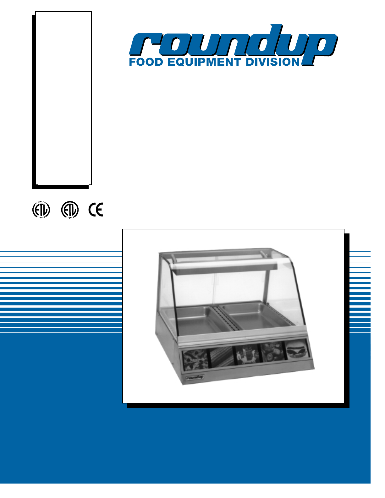
DISPLAY CABINETS
HEATED
Model DCH
Owner’s Manual
P/N 1010677 Rev. D 12/99
MANUFACTURING
NUMBERS:
9020440
9020442
9020444
9020450
9020452
9020455
9020456
9020458
9020460
9020462
9020464
9020465
9020466
9020468
9020470
9020472
9020480
9020481
9020482
9020485
9020486
®
C
US
Page 2

DISPLAY CABINET HEATED
1
P/N 1010677 Rev. D 12/99
A.J. Antunes & Co.
General
The Roundup Display Case attractively displays your
food and maintains it at ready-to-eat temperature. A
convection fan circulates oven heat throughout the
entire display cabinet while a digitally controlled thermostat maintains a constant temperature. Humidity
water trays extend food holding times by reducing
moisture loss.
Models DCH-10, DCH-20 and DCH-30 are designed
for POTENTIALLY HAZARDOUS FOOD display.
Models DCH-12, DCH-22 & DCH-32 are designed for
NON-POTENTIALLY HAZARDOUS FOOD display.
This manual provides the safety, installation and operating procedures for the unit. We recommend that all
information contained in this manual be read prior to
installing and operating the unit.
This unit is manufactured from the finest materials
available and is assembled to Roundup’s strict quality
standards. This unit has been tested at the factory to
ensure dependable trouble-free operation.
OWNER INFORMATION
Installation
.................................................................6
Unpacking .................................................................6
Equipment Setup ......................................................6
Operation
...................................................................7
General ......................................................................7
Operating Instructions ...............................................7
Maintenance
.............................................................8
Cleaning ...................................................................8
Parts Replacement....................................................8
Troubleshooting
......................................................11
Replacement Parts ............................................
12-19
Wiring Diagram .......................................................
20
Warranty ....................................................
Back Cover
Owner Information
.....................................................1
General ......................................................................1
Warranty Information .................................................1
Service/Technical Assistance ....................................2
Important Safety Information
...................................2
Specifications
............................................................4
Electrical Ratings ......................................................4
Electrical Cord & Plug Configurations ......................4
Model Designation ....................................................4
Temperature Ranges ................................................5
Capacities .................................................................5
Dimensions ...............................................................5
TABLE OF CONTENTS
IMPORTANT! Keep these instructions for future reference.
If the unit changes ownership, be sure this manual accompanies the equipment.
Warranty Information
Please read the full text of the Limited Warranty in this
manual.
If the unit arrives damaged, contact the carrier
immediately and file a damage claim with them.
Save all packing materials when filing a claim. Freight
damage claims are the responsibility of the purchaser
and are not covered under warranty.
The warranty does not extend to:
• Damages caused in shipment or damage as
result of improper use.
• Installation of electrical service.
• Normal maintenance as outlined in this manual.
• Malfunction resulting from improper maintenance.
• Damage caused by abuse or careless handling.
• Damage from moisture into electrical
components.
• Damage from tampering with, removal of, or
changing any preset control or safety device.
Page 3
WARNING
GENERAL WARNING. Indicates information important to the proper operation of
the equipment. Failure to observe may
result in damage to the equipment and/or
severe bodily injury or death.
Throughout this manual, you will find the following safety words and symbols that signify important safety issues with
regards to operating or maintaining the equipment.
WARNING
ELECTRICAL WARNING. Indicates information relating to possible shock hazard.
Failure to observe may result in damage
to the equipment and/or severe bodily
injury or death.
CAUTION
GENERAL CAUTION. Indicates information important to the proper operation of
the equipment. Failure to observe may
result in damage to the equipment.
WARNING
HOT SURFACE WARNING. Indicates information important to the handling of
equipment and parts. Failure to observe
caution could result in personal injury.
IMPORTANT SAFETY INFORMATION
DISPLAY CABINET HEATED
2
P/N 1010677 Rev. D 12/99
A.J. Antunes & Co.
Service/Technical Assistance
If you experience any problems with the installation or
operation of your unit, contact your local Roundup
Authorized Service Agency.
Fill in the information below and have it handy
when calling your authorized service agency for
assistance. The serial number is on the specification
plate located on the unit.
Purchased From:
Date of Purchase:
Model No.:
Serial No.:
Mfg. No.:
OWNER INFORMATION (continued)
Refer to the service agency directory included with
your unit.
Authorized Service Agency
Name:
Phone No.:
Address:
Use only genuine Roundup replacement parts in
this unit. Use of replacement parts other than those
supplied by the manufacturer will void the warranty.
Your Authorized Service Agency has been factory
trained and has a complete supply of parts for this unit.
You may also contact the factory at 1-877-392-7854 if
you have trouble locating your local authorized service
agency.
IMPORTANT
A.J. Antunes & Co. reserves the right to change specifications and product design without
notice. Such revisions do not entitle the buyer to corresponding changes, improvements, additions or replacements for previously purchased equipment.
Page 4

DISPLAY CABINET HEATED
3
P/N 1010677 Rev. D 12/99
A.J. Antunes & Co.
In addition to the warnings and cautions in this manual,
use the following guidelines for safe operation of the
unit.
• Read all instructions before using equipment.
• For your safety, the equipment is furnished with a
properly grounded cord connector. Do not
attempt to defeat the grounded connector.
• Install or locate the equipment only for its intended use as described in this manual.
• Do not operate this equipment if it has a damaged cord or plug, if it is not working properly, or
if it has been damaged or dropped.
• This equipment should be serviced by qualified
personnel only. Contact the nearest Roundup
authorized service facility for adjustment or repair.
• Do not block or cover any openings on the unit.
• Keep cord away from heated surfaces.
• Do not allow cord to hang over edge of table or
counter.
The following warnings and cautions appear
throughout this manual and should be carefully
observed.
• Turn the unit off, disconnect the power source
and allow unit to cool down before performing
any service or maintenance on the unit.
• The procedures in this chapter may include
the use of chemical products. These chemical
products will be highlighted with bold face letters followed by the abbreviated HCS (Hazard
Communication Standard). See Hazard
Communication Standard manual for the
appropriated Material Safety Data Sheets
(MSDS).
• The unit should be grounded according to
local electrical codes to prevent the possibility of electrical shock. It requires a grounded
receptacle with separate electrical lines, protected by fuses or circuit breaker of the proper rating.
• All electrical connections must be in accordance with local electrical codes and any
other applicable codes.
• WARNING ELECTRICAL SHOCK HAZARD.
FAILURE TO FOLLOW THESE INSTRUCTIONS
COULD RESULT IN SERIOUS INJURY OR DEATH.
- Electrical ground is required on this appliance.
- Do not modify the power supply cord plug.
If it does not fit the outlet, have a proper
outlet installed by a qualified electrician.
- Do not use an extension cord with this
appliance.
- Check with a qualified electrician if you are
in doubt as to whether the appliance is
properly grounded.
• This equipment is to be installed to comply
with the basic plumbing code of the Building
Officials and Code Administration, Inc.
(BOCA) and the Food Service Sanitation
Manual of the Food and Drug Administration
(FDA).
• Do not immerse cord or plug in water.
• Do not clean this appliance with a water jet.
• Do not use a sanitizing solution or abrasive
materials. The use of these may cause damage to the stainless steel finish.
• Do not use corrosive chemicals in this equipment.
• Chlorides or phosphates in cleansing agents
(e.g. bleach, sanitizers, degreasers or detergents) could cause permanent damage to
stainless steel equipment. The damage is usually in the form of discoloration, dulling of
metal surface finish, pits, voids, holes or
cracks. This damage is permanent and not
covered by warranty.
• The following tips are recommended for maintenance of your stainless steel equipment.
- Always use soft, damp cloth for cleaning,
rinse with clear water and wipe dry. When
required, always rub in direction of metal
polish lines.
- Routine cleaning should be done daily
using soap, ammonia detergent and water.
- Stains and spots should be sponged
using a vinegar solution as required.
- Finger marks and smears should be
rubbed off using soap and water.
- Hard water spots should be sponged
using a vinegar solution.
Page 5
DISPLAY CABINET HEATED
4
P/N 1010677 Rev. D 12/99
A.J. Antunes & Co.
Model Voltage Watts Amps Hertz
DCH-10/12 120 1550 12.9 50/60
DCH-20 208/220 2100 8.8 50/60
DCH-22/32 120 1800 15.0 50/60
DCH-30/32 208 2900 12.1 50/60
220-240
SPECIFICATIONS
Electrical Ratings
Electrical Cord & Plug Configurations
CAUTION
All electrical connections must be in accordance
with local electrical codes and any other applicable codes.
WARNING
ELECTRICAL SHOCK HAZARD. FAILURE TO FOL-
LOW THE INSTRUCTIONS IN THIS MANUAL
COULD RESULT IN SERIOUS INJURY OR DEATH.
• Electrical ground is required on this appliance.
• Do not modify the power supply cord plug. If it
does not fit the outlet, have a proper outlet
installed by a qualified electrician.
• Do not use an extension cord with this appliance.
• Check with a qualified electrician if you are in
doubt as to whether the appliance is properly
grounded.
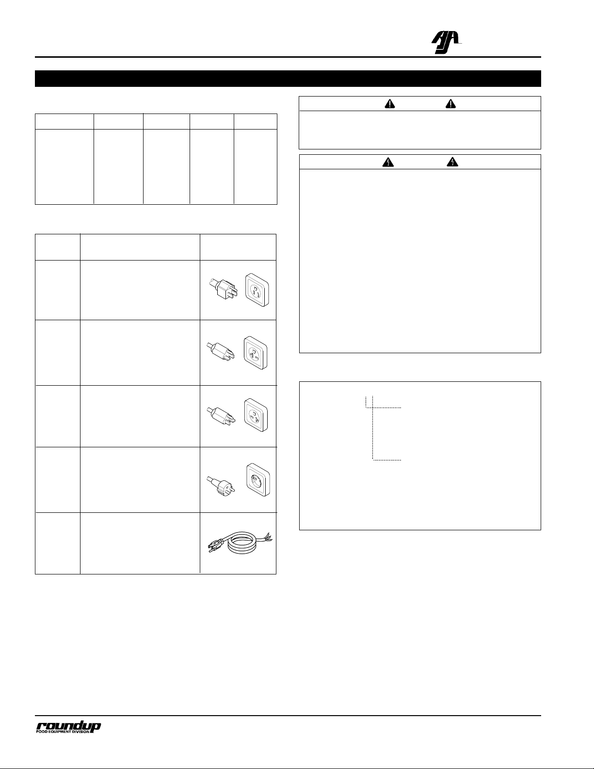
Letter Description Configuration
Code*
F NEMA-5-15P
15 Amp, 120 VAC
T NEMA 5-20P
20 Amp, 120 VAC
V NEMA 6-20P
20 Amp, 250 VAC
C CEE 7/7 Schuko
20 Amp, 250 VAC
C Commercial Cord
H Harmonized Cord
* Used in model designation.
Model Designation
TYPE OF POWER CORD
H = HARMONIZED
C = COMMERCIAL
TYPE OF PLUG
C = CEE 7/7 Schuko
F = NEMA 5-15P
T = NEMA 5-20P
V = NEMA 6-20P
DCH-10 XX
DCH-12
DCH-20
DCH-22
DCH-30
DCH-32
Page 6
DISPLAY CABINET HEATED
5
P/N 1010677 Rev. D 12/99
A.J. Antunes & Co.
Capacities
DCH-10/DCH-12
• One 2-1/2" (63.5 mm) deep full size steam table
pan.
• One water tray at 4 quarts (3.8 liters).
DCH-20/DCH-22
• Two 2-1/2" (63.5 mm) deep full size steam table
pans.
• Two water trays at 4 quarts (3.8 liters) each.
DCH-30/DCH-32
• Three 2-1/2" (63.5 mm) deep full size steam table
pans.
• Two water trays at 5 quarts (4.7 liters) each.
Temperature Ranges
DCH-10: 150°-165°F (66°-74°C)
DCH-12: 100°-165°F (38°-74°C)
DCH-20: 150°-165°F (66°-74°C)
DCH-22: 100°-165°F (38°-74°C)
DCH-30: 150°-165°F (66°-74°C)
DCH-32: 100°-165°F (38°-74°C)
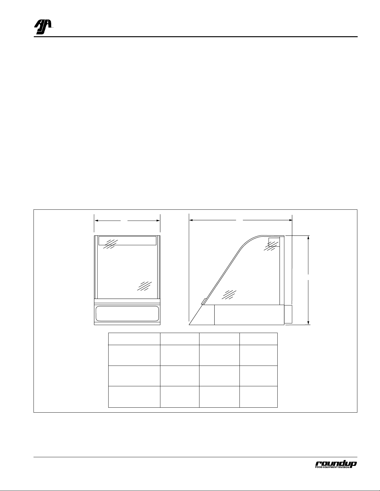
Dimensions
Model Dim. A Dim. B Dim. C
DCH-10 15-1/8" 30-1/4" 22-13/32"
DCH-12 (384 mm) (768 mm) (569 mm)
DCH-20 30-1/4" 30-1/4" 22-13/32"
DCH-22 (768 mm) (768 mm) (569 mm)
DCH-30 42-1/16" 30-1/4" 22-13/32"
DCH-32 (1068 mm) (768 mm) (569 mm)
A
B
C
Page 7
DISPLAY CABINET HEATED
6
P/N 1010677 Rev. D 12/99
A.J. Antunes & Co.
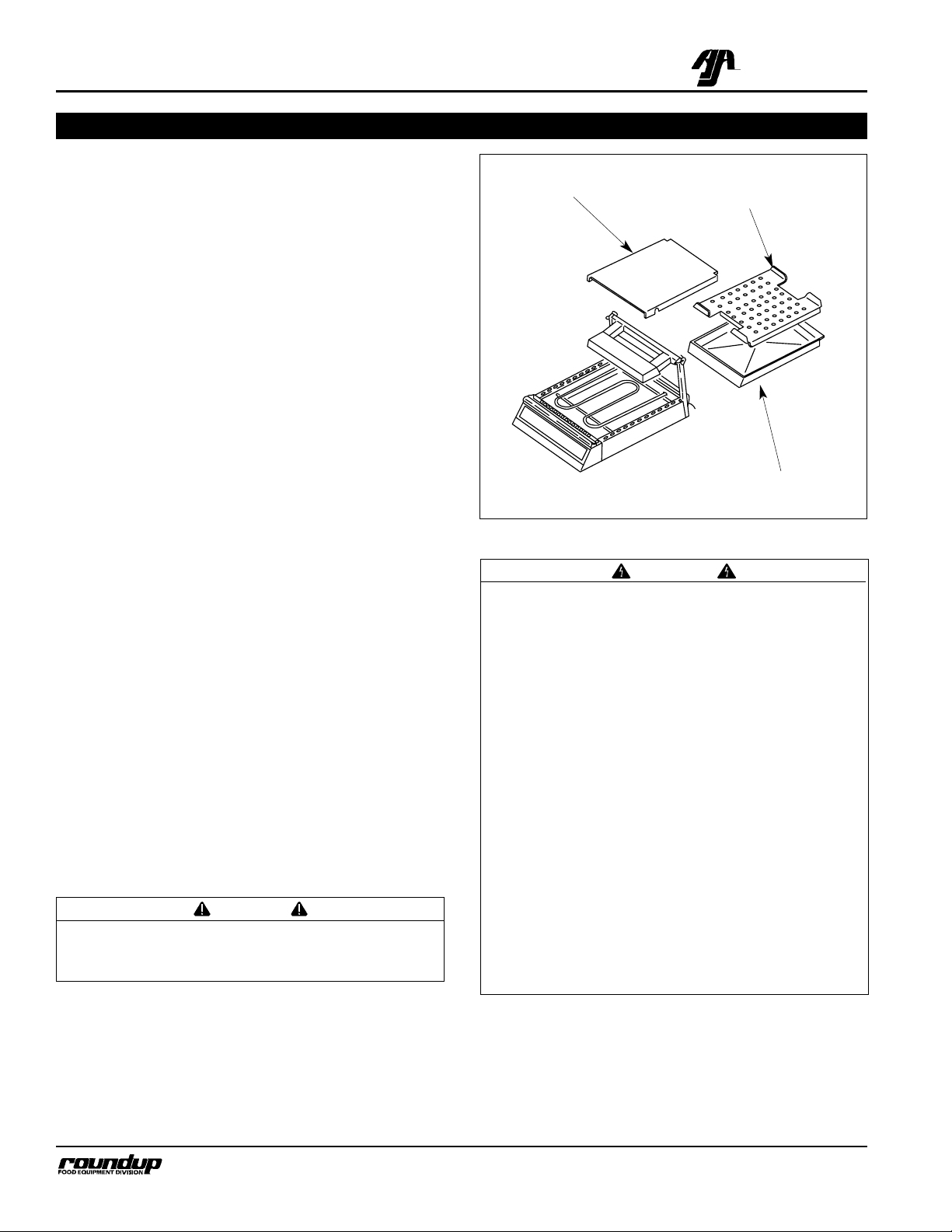
Figure 1. Display Components (DCH-10 Shown)
Unpacking
1. Remove unit and all packing materials from shipping carton.
2. Open the large box. Remove all packing materials and protective coverings from the unit and
parts.
NOTE: If any parts are missing or damaged, contact
Antunes Technical Service IMMEDIATELY at 1-877392-7854.
3. Wash all components in soap and water. Wipe all
surfaces of the unit with a hot damp cloth.
NOTE: Do not use a dripping wet cloth. Wring out
before use.
4. Install components in unit.
Equipment Setup
When placing the unit into service, pay attention to the
following guidelines.
• Make sure power to the unit is off and the unit is
at room temperature.
• Do not block or cover any openings on the unit.
• Do not immerse cord or plug in water.
• Keep cord away from heated surfaces.
• Do not allow cord to hang over edge of table or
counter.
• Place unit on a sturdy, level table or work surface.
• Ensure that the line voltage corresponds to the
stated voltage on the unit specification label.
• Turn off the rocker switch. Connect the unit to the
power supply.
INSTALLATION
CAUTION
All electrical connections must be in accordance
with local electrical codes and any other applicable codes.
WARNING
ELECTRICAL SHOCK HAZARD. FAILURE TO FOL-
LOW THE INSTRUCTIONS IN THIS MANUAL
COULD RESULT IN SERIOUS INJURY OR DEATH.
• Electrical ground is required on this appliance.
• Do not modify the power supply cord plug. If it
does not fit the outlet, have a proper outlet
installed by a qualified electrician.
• Do not use an extension cord with this appliance.
• The unit should be grounded according to local
electrical codes to prevent the possibility of
electrical shock. It requires a grounded receptacle with separate electrical lines, protected by
fuses or circuit breaker of the proper rating.
• Check with a qualified electrician if you are in
doubt as to whether the appliance is properly
grounded.
Water Tray
Diffuser
Heat Shield
Page 8

DISPLAY CABINET HEATED
7
P/N 1010677 Rev. D 12/99
A.J. Antunes & Co.
Figure 2. Filling Water Tray (DCH-10 Shown)
Figure 3. Controls
Figure 4. Loading Food (DCH-10 Shown)
1. Slide the water tray(s) out until rectangular opening is exposed and fill with clean tap water
(Figure 2). See
Specifications
for tray capacity.
2. Carefully push tray into unit avoiding any spillage.
3. Set the rocker switch (Figure 3) to the ON position.
4. To set desired temperature, depress and hold the
temperature button (Figure 3) while turning the
temperature control knob to the desired setting
(setpoint).
IMPORTANT: Setpoint temperature can be changed
without depressing the temperature button, so do
not turn the temperature control knob unless you
want to change the setpoint temperature.
IMPORTANT: Models DCH-12, DCH-22 and DCH-32
have a temperature range of 100°-165°F (38°-74°C)
which is below the safe holding temperature for
some foods. Only non-potentially hazardous food
should be held in these units.
NOTE: Setpoint temperature is the desired temperature setting. Indicated temperature is the actual temperature inside the cabinet. When the temperature button is depressed and held, setpoint temperature is displayed; when released, the indicated temperature is
displayed.
5. The unit will reach the desired temperature and
humidity in 30-45 minutes.
NOTE: If more humidity is desired, remove one or
more tray diffusers. If not humidity is desired, operate
the unit without water in the water tray(s).
6. Open the rear door and place the serving table
pan(s) into the unit (Figure 4). Load the pan(s)
with food using tongs or similar utensil. Close the
door.
OPERATION
Rocker Switch (Power On/Off)
Specification Tag
Temperature Button
Temperature Control Knob
Page 9

3. Wash all components in soap and water. Wipe all
surfaces of the unit with a hot damp cloth.
NOTE: Do not use a dripping wet cloth. Wring out
before use.
4. Wash and dry all surfaces of the unit.
5. Install components in unit.
Parts Replacement
HEAT LAMP REPLACEMENT
1. Turn rocker switch to the OFF position.
2. Unplug the power cord from the electrical outlet
and allow the unit to cool to room temperature
before proceeding.
3. Gently, but firmly, depress the lamp socket and
remove the lamp (Figure 5).
4. Install a new lamp while depressing the socket.
Make sure lamp is fully seated before releasing
socket.
DISPLAY CABINET HEATED
8
P/N 1010677 Rev. D 12/99
A.J. Antunes & Co.
MAINTENANCE
WARNING
Do not use a sanitizing solution or abrasive materials. The use of these may cause damage to the
stainless steel finish.
WARNING
All glass surfaces must be cool before cleaning.
Once cool, wipe glass with a clean cloth. Do not
attempt to clean glass when hot or with cold towel
as shattering glass may occur.
WARNING
All glass surfaces must be cool before cleaning.
Once cool, wipe glass with a clean cloth. Do not
attempt to clean glass when hot or with cold towel
as shattering glass may occur.
CAUTION
Chlorides or phosphates in cleaning agents (e.g.
bleach, sanitizers, degreasers or detergents) could
cause permanent damage to stainless steel equipment. The damage is usually in the form of discoloration, dulling of metal surface finish, pits,
voids, holes or cracks. This damage is permanent
and not covered by warranty. The following tips
are recommended for maintenance of your stainless steel equipment:
• Always use soft, damp cloth for cleaning, rinse
with clear water and wipe dry. When required,
always rub in direction of metal polish lines.
• Routine cleaning should be done daily using
soap, ammonia detergent and water.
• Stains and spots should be sponged using a
vinegar solution.
• Finger marks and smears should be rubbed off
using soap and water.
• Hard water spots should be sponged using a
vinegar solution.
WARNING
Turn the unit off, disconnect the power source and
allow the unit to cool down before performing any
service or maintenance on the unit.
CAUTION
Do not handle heat lamp with fingers. Use a tissue or clean cloth to handle lamps.
Cleaning
The unit requires a minimum amount of maintenance.
To ensure proper operation, clean the unit at the end of
each serving day.
1. Turn rocker switch to the OFF position.
2. Unplug the power cord from the electrical outlet
and allow the unit to cool to room temperature
before proceeding.
WARNING
Do not remove water tray(s) or pan(s) while unit is
hot or personal injury may result.
Figure 5. Heat Lamp Replacement
Page 10

DISPLAY CABINET HEATED
9
P/N 1010677 Rev. D 12/99
A.J. Antunes & Co.
Figure 6. Display Lamp Replacement
FRONT DISPLAY GRAPHICS OR LAMP REPLACEMENT
1. Turn rocker switch to the OFF position.
2. Unplug the power cord from the electrical outlet
and allow the unit to cool to room temperature
before proceeding.
3. Unplug the power cord from the electrical outlet
and allow the unit to cool to room temperature
before proceeding.
4. Using a screwdriver or similar flatbladed tool,
gently pry one side of the display panel assembly
from the unit (Figure 6), then remove the panel.
5. DCH-10/12: Remove lamp by gently turning it
counterclockwise. Install a new lamp.
DCH-20/22/30/32: Remove fluorescent tube by
gently turning it up and out of the sockets.
Remove bulb deflector and install on new tube,
then install tube into unit.
6. Install new graphics by removing the white diffuser plate and transparency holder. Replace
transparency and reinstall holder and plate.
REAR DOOR REPLACEMENT
DCH-10/12 Models
1. Turn rocker switch to the OFF position.
2. Unplug the power cord from the electrical outlet
and allow the unit to cool to room temperature
before proceeding.
3. Open the rear door and lift off the hinge pins.
4. Place new door on hinge pins and slide door
down into track.
DCH-20/22/30/32 Models
1. Turn rocker switch to the OFF position.
2. Unplug the power cord from the electrical outlet
and allow the unit to cool to room temperature
before proceeding.
3. Firmly grasp the sides of one glass door. Lift the
door up and out of the bottom track. Repeat for
the other door.
4. Place new door in the inside upper track. Push
up firmly and slide bottom of door into bottom
inside track. Install other door into outside tracks
the same way.
DCH-10/12
DCH-20/22/30/32
Figure 7. Rear Door(s) Removal/Installation
Page 11

DISPLAY CABINET HEATED
10
P/N 1010677 Rev. D 12/99
A.J. Antunes & Co.
MAINTENANCE (continued)
FRONT GLASS PANEL REPLACEMENT
1. Turn rocker switch to the OFF position.
2. Unplug the power cord from the electrical outlet
and allow the unit to cool to room temperature
before proceeding.
3. Loosen the screw securing each top glass retainer. Slide retainer up and to the rear.
4. Tilt front glass panel assy. forward on the hinge
plate and remove from unit.
5. To reinstall, be sure glass panel assy. is fully seated in hinge plate, then tilt panel assy. fully rearward. Secure with top retainer and tighten
screws.
SIDE GLASS REPLACEMENT
1. Turn rocker switch to the OFF position.
2. Unplug the power cord from the electrical outlet
and allow the unit to cool to room temperature
before proceeding.
3. Remove the screws securing each top retainer
and remove retainers.
4. Tilt front glass panel assy. forward on the hinge
plate and remove from unit.
CAUTION
Front glass panel replacement should be performed by two people to prevent damage to the
glass.
Figure 7. Glass Panel (s) Replacement
Top Glass
Retainer Assy.
Front Glass
Panel
Top Cap
Assy.
Side Glass
5. Remove both top cap assys.
6. Lift side glass panel up and forward to remove it
from the glass clips.
7. To reinstall, position side glass panel into glass
clips. Push fully rearward. Reinstall front glass
panel assy.
8. Secure with top caps and retainers. Tighten
screws.
Page 12

DISPLAY CABINET HEATED
11
P/N 1010677 Rev. D 12/99
A.J. Antunes & Co.
TROUBLESHOOTING
WARNING
To avoid possible personal injury and/or damage to the unit, inspection, test and repair of electrical equipment should be performed by qualified service personnel. The unit should be unplugged when servicing.
Unit does not operate.
Temperature display does
not light.
No heat.
Display panel does not light.
Halogen heat lamp(s) will
not light.
No power.
Defective electrical outlet.
Loose connection.
Defective power cord or plug.
Defective rocker switch (power on/off).
Defective temperature display control.
Defective heating element(s).
Defective thermocouple.
Defective solid state relay.
Defective stepdown transformer.
Light bulb burned out.
DCH-20/22/30/32 only. Defective
ballast.
Heat lamp(s) burned out.
Defective resistor assy.
Faulty quartz lamp socket.
Check that power cord is plugged in. Check
fuse or circuit breaker.
Plug unit into another outlet or have outlet
replaced.
Check and tighten all electrical connections.
Replace power cord.
Replace switch.
Replace control.
Replace heating element(s).
Replace thermocouple.
Replace solid state relay.
Replace transformer.
Replace light.
Replace ballast.
Replace heat lamp(s).
Replace resistor assy.
Replace socket.
Problem Possible Cause Corrective Action
Page 13

DISPLAY CABINET HEATED
12
P/N 1010677 Rev. D 12/99
A.J. Antunes & Co.
REPLACEMENT PARTS – DCH-10/12
1
3
7
58
57
6
5
4
34
33
31
47
30
28
29
32
14
27
35
50
43
42
36
50
60
59
23
22
48
19
54
50
44
2
41
47
40
61
56
37
26
38
52
46
21
55
24
49
17
54
15
39
20
25
50
55
51
16
45
49
11
53
12
47
14
18
10
8
9
12
13
F
60
Page 14

DISPLAY CABINET HEATED
13
P/N 1010677 Rev. D 12/99
A.J. Antunes & Co.
1 0011103 Front Glass Panel Assy. 1
2 0021057 Inner Lamp Housing Weldment 1
3 0011107 Resistor Assy. 1
4 0503046 Housing, Lamp 1
5 0900214 Rear Door 1
6 2110139 Hinge, Lift-Off 2
7 2100145 Knob, Cover 1
8 0503044 Diffuser, Water Tray 1
9 0503038 Water Tray 1
10 0502172 Heat Shield 1
11 0021058 Control Panel Weldment 1
12 402K172 Temperature Control Display,
150°-165°F (66°-74°C), DCH-10 1
7000118 Temperature Control Display,
100°-165°F (38°-74°C), DCH-12 1
13 4010151 Rocker Switch, Power On/Off 1
14 0900143 Side Glass 1
15 0020702 Heat Sink Assy. 2
16 4010159 Transformer, 120V/12V 1
17 405K125 Relay, Solid State 1
18 4060304 Terminal Block, 3-Pole 1
19 4060341 Terminal Block, 8-Pole 1
20 0502045 Retainer, Glass, LH** 1
0502044 Retainer, Glass, RH** 1
21 0020670 Top Cap Assy., LH** 1
0020669 Top Cap Assy., RH** 1
22 0502866 Cover, Lamp Housing Bracket 1
23 0502865 Bracket, Lamp 1
24 0501946 Grill, Blower 1
25 0700463 Power Cord w/Plug, NEMA 5-15P 1
26 020K110 Gasket Kit, Bottom 1
27 0503042 Lamp, Bulkhead 1
28 4060360 Candelabra Lamp Holder 4
29 0503052 Bracket, Lamp 1
30 4060359 Lamp, 120V, 10 Watt 4
31 0900216 Diffuser Panel 1
32 2070120 Nipple, 1/8-27 1
33 0900215 Display Panel 1
34 0021056 Display Frame Weldment 1
35 400K123 Blower Kit, 120V 1
36 0200202 Magnetic Strip 1
37 5040036 Base Hinge Assy. 1
38 4030305 Heating Element, 120V 1
39 4050163 Thermocouple Assy. 1
40 0503037 Duct, Access Cover 1
41 0503045 Heat Deflector 1
42 4060252 Lamp, Quartz Halogen, 100 Watt 1
43 4060189 Lamp Holder, Quartz 2
44 0800316 Guard, Lamp 1
45 040P138* Strain Relief w/Locknut 1
46 210P116* Rubber Bumper Pad 1
47 306P101* Nut, Hex, #6-32, SS 1
48 306P105* Screw, #6-32 x 1/2, SS 1
49 306P130* Nut, Hex, KEPS, #6-32 1
50 308P103* Screw, #8-32 x 1/4, One-Way 6
51 308P124* Screw, #8-32 x 1/2, One-Way 1
52 308P127* Screw, #8-32 x 5/16, SS 1
53 308P143* Nut, Hex, KEPS, #8-32 1
54 308P144* Screw, #8-32 x 1/4, #6 Head 2
55 308P159* Thumbscrew, #8-32 x 11/32 1
56 310P146* Nut, Hex, KEPS, #10-32 1
57 310P110* Screw, #10-32 x 1/2, SS 4
58 310P123* Screw, #10-24 x 1/2, SS 1
59 040P111* Snap Bushing 2
60 306P123* Screw, #6-32 x 7/8 2
61 308P151* Screw, #8-32 x 5/16" 1
Item Part Description Qty.
No.
Item Part Description Qty.
No.
REPLACEMENT PARTS – DCH-10/12
* Only available in packages of 1
0.
** LH/RH is determined by viewing front of curved glass panel.
Page 15

DISPLAY CABINET HEATED
14
P/N 1010677 Rev. D 12/99
A.J. Antunes & Co.
REPLACEMENT PARTS – DCH-20/22/30/32
1
3
57
43
34
14
33
32
31
30
42
29
46
45
35
50
36
44
41
40
51
2
53
57
57
37
38
39
5
4
6
7
8
9
55
49
58
21
24
47
56
57
19
20
18
22
58
23
53
56
52
54
25
17
48
16
14
10
15
11
12
13
56
28
27
59
26
Page 16

DISPLAY CABINET HEATED
15
P/N 1010677 Rev. D 12/99
A.J. Antunes & Co.
REPLACEMENT PARTS – DCH-20/22/30/32
1 0011002 Front Glass Panel Assy. 1 1 - - -
0011003 Front Glass Panel Assy. - - 1 1 1
2 0020922 Inner Lamp Housing Weldment 1 1 - - -
0020923 Inner Lamp Housing Weldment - - 1 1 1
3 0010706 Resistor Assy., 120V - 1 - - 1
0010664 Resistor Assy., 208V 1 - 1 1 4 0502895 Housing, Lamp 1 1 - - -
0502850 Housing, Lamp - - 1 1 1
5 0800236 Display Rack (Optional) 1 1 - - -
0500237 Display Rack (Optional) - - 1 1 1
6 0010704 Sliding Door Assy., Clear Glass 2 - - - -
0010705 Sliding Door Assy., Clear Glass - - 2 2 2
0011133 Sliding Door Assy., Mirrored Glass
(Mfg. No. 9020481 only) - 2 - - -
7 0501820 Support, Center Pan 1 1 - - -
0501869 Support, Center Pan - - 2 2 2
8 0501965 Diffuser, Water Tray 2 2 - - -
0501966 Diffuser, Water Tray - - 2 2 2
9 0501807 Water Tray 2 2 - - -
0501866 Water Tray - - 2 2 2
10 0502172 Heat Shield 22333
11 0020744 Control Panel Weldment 1 1 - - -
0020745 Control Panel Weldment 00111
12 402K172 Temperature Control Display, 150°-165°F1 - 1 - -
403K276 Temperature Control Display, 65°-75°C
(Mfg. Nos. 9020458/468/456/466 only) - - 1 - -
7000118 Temperature Control Display, 100°-165°F- 1 - 1 1
13 4010110 Rocker Switch, Power On/Off 11111
14 0900143 Side Glass 22222
15 0020702 Heat Sink Assy. 11111
16 4010142 Transformer, 240V/12V 1 - 1 1 -
4010159 Transformer, 120V/12V - 1 - - 1
17 405K125 Transformer, 230V/115V 1 - 1 1 18 4010159 Relay, Solid State 11111
19 0010494 Ballast Assy., 20 Watt Lamp 1 1 - - -
0010495 Ballast Assy., 30 Watt Lamp - - 1 1 1
20 0502045 Retainer, Glass, LH** 11111
0502044 Retainer, Glass, RH** 11111
21 0020670 Top Cap Assy., LH** 11111
0020669 Top Cap Assy., RH** 11111
22 2100183 Door Track, Upper 1 1 - - -
2100185 Door Track, Upper 00111
23 2100184 Door Track, Lower 1 1 - - -
2100186 Door Track, Lower - - 1 1 1
24 0501946 Grill, Blower 11222
Item Part Description Qty.
(240V) (120V)
No.
DCH-20 DCH-22 DCH-30 DCH-32 DCH-32
* Only available in packages of 1
0.
** LH/RH is determined by viewing front of curved glass panel.
Page 17

DISPLAY CABINET HEATED
16
P/N 1010677 Rev. D 12/99
A.J. Antunes & Co.
REPLACEMENT PARTS – DCH-20/22/30/32 (continued)
1
3
57
43
34
14
33
32
31
30
42
29
46
45
35
50
36
44
41
40
51
2
53
57
57
37
38
39
5
4
6
7
8
9
55
49
58
21
24
47
56
57
19
20
18
22
58
23
53
56
52
54
25
17
48
16
14
10
15
11
12
13
56
28
27
59
26
Page 18

DISPLAY CABINET HEATED
17
P/N 1010677 Rev. D 12/99
A.J. Antunes & Co.
REPLACEMENT PARTS – DCH-20/22/30/32 (continued)
25 0700388 Power Cord w/Plug, NEMA 6-20P 1 - 1 1 -
0700448 Power Cord w/Plug, NEMA 5-20P - 1 - - 1
0700475 Power Cord w/Plug, CEE 7/7
(International only) 11111
26 020K107 Gasket Kit, Bottom 1 1 - - -
020K108 Gasket Kit, Bottom - - 1 1 1
27 0501849 Lamp, Bulkhead 1 1 - - -
0501874 Lamp, Bulkhead - - 1 1 1
28 4060253 Fluorescent Lampholder 22222
29 0502178 Reflector Bulb 1 1 - - -
0502179 Reflector Bulb - - 1 1 1
30 4060254 Fluorescent Bulb, 20 Watt 1 1 - - -
4060255 Fluorescent Bulb, 30 Watt - - 1 1 1
31 0900151 Diffuser Panel 1 1 - - -
0900153 Diffuser Panel - - 1 1 1
32 0900173 Transparency Holder 1 1 - - -
0900174 Transparency Holder - - 1 1 1
33 0900150 Display Panel 1 1 - - -
0900152 Display Panel - - 1 1 1
34 0020673 Display Frame Weldment 1 1 - - -
0020674 Display Frame Weldment - - 1 1 1
35 400K116 Blower Kit, 230V 1 - 2 2 -
400K123 Blower Kit, 120V - 1 - - 2
36 0200154 Magnetic Strip 2 2 - - -
0200155 Magnetic Strip - - 2 2 2
37 5040027 Base Hinge Assy. 11111
38 4030239 Heating Element, 230V, 825 Watts 2 - 3 3 -
4030278 Heating Element, 120V, 700 Watts - 2 - - -
4030304 Heating Element, 120V, 500 Watts ----3
39 7000227 Thermocouple Kit 11111
40 0501806 Duct, Access Cover 1 1 - - -
0501865 Duct, Access Cover 00111
41 0502555 Heat Deflector 1 1 - - -
0502556 Heat Deflector - - 1 1 1
42 4060252 Lamp, Quartz Halogen, 100 Watt 22222
43 4060189 Lamp Holder, Quartz 44444
44 0800224 Guard, Lamp 1 1 - - -
0800229 Guard, Lamp - - 1 1 1
45 0502866 Cover, Lamp Housing Bracket 22222
46 0502865 Bracket, Lamp Housing 22222
47 2040123 Connector, Male, 1/8 x 1/8 11111
48 040P112* Strain Relief w/Locknut 111149 210P116* Rubber Bumper Pad 111150 306P101* Nut, Hex, #6-32, SS 1111-
Item Part Description Qty.
(240V) (120V)
No.
DCH-20 DCH-22 DCH-30 DCH-32 DCH-32
* Only available in packages of 1
0.
** LH/RH is determined by viewing front of curved glass panel.
continued on next page
Page 19

DISPLAY CABINET HEATED
18
P/N 1010677 Rev. D 12/99
A.J. Antunes & Co.
REPLACEMENT PARTS – DCH-20/22/30/32 (continued)
1
3
57
43
34
14
33
32
31
30
42
29
46
35
50
45
36
44
41
40
51
2
53
57
57
37
38
39
5
4
6
7
8
9
55
49
21
58
24
47
56
19
57
20
18
22
58
23
53
56
52
54
25
17
48
16
14
10
15
11
12
13
56
28
27
59
26
Page 20

DISPLAY CABINET HEATED
19
P/N 1010677 Rev. D 12/99
A.J. Antunes & Co.
REPLACEMENT PARTS – DCH-20/22/30/32 (continued)
51 306P105* Screw, #6-32 x 1/2, SS 111152 306P130* Nut, Hex, KEPS, #6-32 111153 308P103* Screw, #8-32 x 1/4, One-Way 666654 308P124* Screw, #8-32 x 1/2, One-Way 111155 308P127* Screw, #8-32 x 5/16, SS 111156 308P143* Nut, Hex, KEPS, #8-32 111157 308P144* Screw, #8-32 x 1/4, #6 Head 222258 308P159* Thumbscrew, #8-32 x 11/32 111159 310P146* Nut, Hex, KEPS, #10-32 111160 310P110* Screw, #10-32 x 1/2, SS 444461 310P123* Screw, #10-24 x 1/2, SS 111162 040P111* Snap Bushing 222263 308P105* Screw, #8-32 x 1/2, SS 22222
Item Part Description Qty.
(240V) (120V)
No.
DCH-20 DCH-22 DCH-30 DCH-32 DCH-32
* Only available in packages of 1
0.
** LH/RH is determined by viewing front of curved glass panel.
Page 21

DISPLAY CABINET HEATED
20
P/N 1010677 Rev. D 12/99
A.J. Antunes & Co.
WIRING DIAGRAMS
DCH-10/12 (120V) DCH-20/30/32 (240V)
DCH-22/32 (120V)
Page 22

A.J. ANTUNES & CO.
180 Kehoe Blvd. • Carol Stream, Illinois 60188
Telephone (630) 784-1000 • FAX (630) 784-1650 • 1-877-392-7854
www.ajantunes.com
LIMITED WARRANTY
Equipment manufactured by Roundup Food Equipment Division of A.J. Antunes & Co. has been constructed of the finest
materials available and manufactured to high quality standards. These units are warranted to be free from mechanical
and electrical defects for a period of one year from date of purchase or 18 months from shipment from factory, whichever
occurs first, under normal use and service, and when installed in accordance with manufacturer’s recommendations.
To insure continued proper operation of the units, follow the maintenance procedure outlined in the Owner’s Manual.
1.This warranty does not cover cost of installation, defects caused by improper storage or handling prior to placing of the
Equipment. This warranty does not include overtime charges or work done by unauthorized service agencies or personnel.
This warranty does not cover normal maintenance, calibration, or regular adjustments as specified in operating and maintenance instructions of this manual, and/or labor involved in moving adjacent objects to gain access to the Equipment. This
warranty does not pay travel, mileage, or any other charges for an authorized service agency to reach the equipment location.
2.Roundup reserves the right to make changes in design or add any improvements on any product. The right is always
reserved to modify equipment because of factors beyond our control and government regulations. Changes to update equipment do not constitute a warranty charge.
3.
If shipment is damaged in transit, the purchaser should make a claim directly upon the carrier. Careful inspection should
be made of the shipment as soon as it arrives and visible damage should be noted upon the carrier’s receipt. Damage
should be reported to the carrier. This damage is not covered under this warranty.
4.Warranty charges do not include freight or foreign, excise, municipal or other sales or use taxes. All such freight and taxes
are the responsibility of the purchaser.
5.THIS WARRANTY IS EXCLUSIVE AND IS IN LIEU OF ALL OTHER WARRANTIES, EXPRESSED OR IMPLIED, INCLUDING ANY IMPLIED WARRANTY OR MERCHANTABILITY OR FITNESS FOR A PARTICULAR PURPOSE, EACH OF
WHICH IS HEREBY EXPRESSLY DISCLAIMED. THE REMEDIES DESCRIBED ABOVE ARE EXCLUSIVE AND IN NO
EVENT SHALL ROUNDUP BE LIABLE FOR SPECIAL CONSEQUENTIAL OR INCIDENTAL DAMAGES FOR THE
BREACH OR DELAY IN PERFORMANCE OF THIS WARRANTY.
 Loading...