

Page 1
MANUFACTURING
A
S
D
L
I
S
T
E
CM
O
I
N
N
I
T
A
T
C
T
I
S
L
US
E
D
NUMBERS:
9500500
9500510
9500512
9500520
9500530
9500531
9500532
9500534
9500536
9500538
9500540
9500550
9500552
9500554
9500556
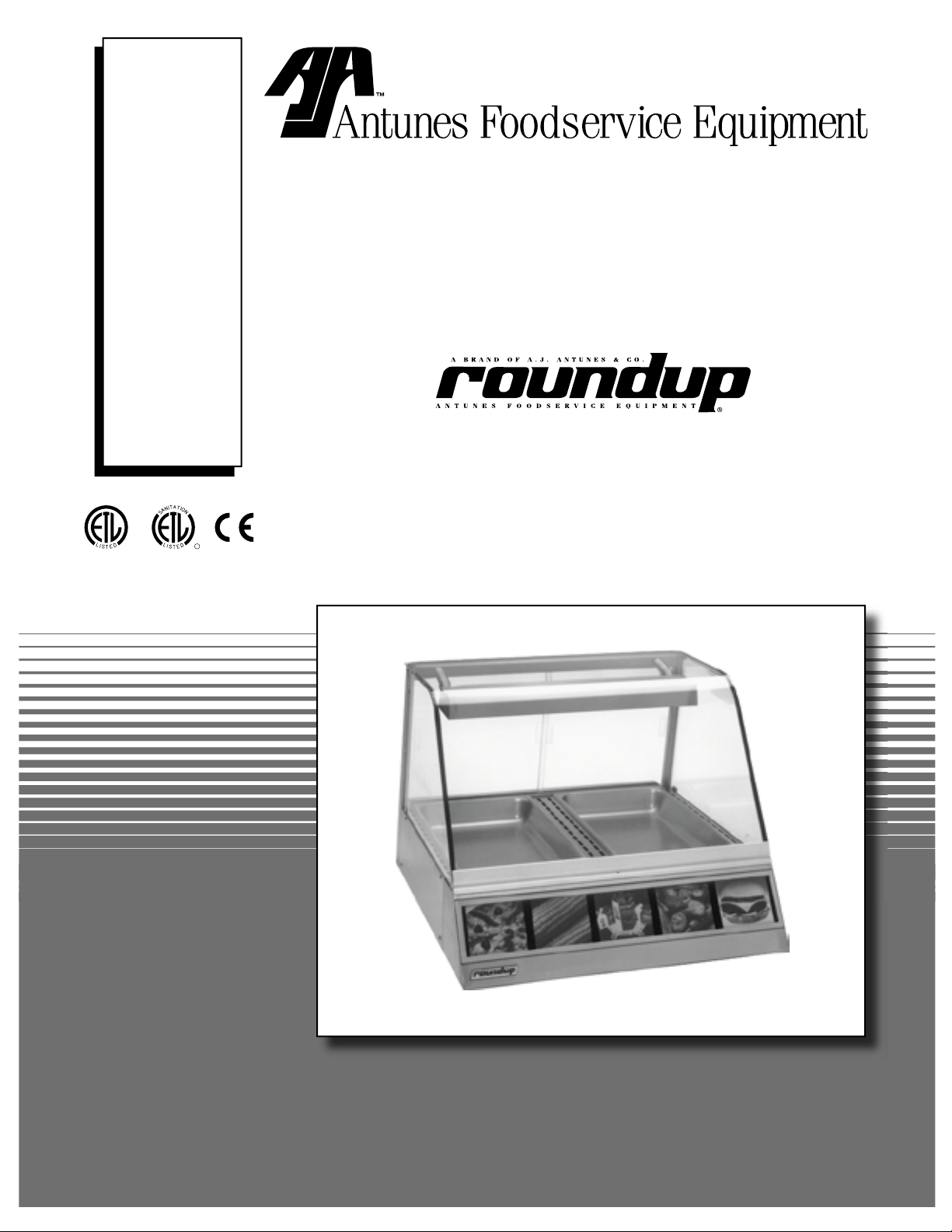
DISPLAY CABINETS
P/N 1010772 Rev. C 01/06
HEATED
Models DCH-100/200/300
DCH-120/220/320
Owner’s Manual
Page 2

DISPLAY CABINET HEATED
TABLE OF CONTENTS
Owner Information .....................................................2
General ......................................................................2
Warranty Information .................................................2
Service/Technical Assistance ....................................3
Important Safety Information ....................................3
Warnings Regarding Handling of Glass ..................5
Specifications .............................................................6
Electrical Ratings .......................................................6
Electrical Cord & Plug Configurations .......................6
Model Designation .....................................................6
Temperature Ranges ................................................7
Dimensions ................................................................7
Capacities .................................................................7
Installation ...................................................................8
Unpacking ..................................................................8
OWNER INFORMATION
General
The Roundup Display Case attractively displays
your food and maintains it at ready-to-eat temperature. A convection fan (some models) circulates heat
throughout the entire display cabinet while a digital
temperature control maintains a constant temperature.
Humidity water trays (some models) extend food holding times by reducing moisture loss.
Models DCH-100, DCH-200, and DCH-300 are primarily for meats and poultry products.
Models DCH-120, DCH-220, and DCH-320 are primarily designed for bread products.
This manual provides the safety, installation and operating procedures for the unit. We recommend that all
information contained in this manual be read prior to
installing and operating the unit.
Operating & Programming ........................................9
Operations and Programming ...................................9
Maintenance .............................................................. 10
Cleaning ................................................................. 10
Parts Replacement ................................................. 10
Technical Theory of Operation ............................... 12
Display Codes ........................................................ 13
Troubleshooting .......................................................14
Replacement Parts – DCH-100/120 .........................15
Replacement Parts – DCH-200/220 .........................17
Replacement parts – DCH-300/320 .........................20
Wiring Diagrams .......................................................22
LIMITED WARRANTY ...............................Back Cover
Warranty Information
Please read the full text of the Limited Warranty in this
manual.
If the unit arrives damaged, contact the carrier
immediately and file a damage claim with them.
Save all packing materials when filing a claim. Freight
damage claims are the responsibility of the purchaser
and are not covered under warranty.
The warranty does not extend to:
• Damages caused in shipment or damage as
result of improper use.
• Installation of electrical service.
• Normal maintenance as outlined in this manual.
• Malfunction resulting from improper maintenance.
This unit is manufactured from the finest materials
available and is assembled to Roundup’s strict quality
standards. This unit has been tested at the factory to
ensure dependable trouble-free operation.
IMPORTANT! Keep these instructions for future reference.
If the unit changes ownership, be sure this manual accompanies the equipment.
• Damage caused by abuse or careless handling.
• Damage from moisture into electrical
components.
• Damage from tampering with, removal of, or
changing any preset control or safety device.
2
P/N 1010772 Rev. C 01/06
Page 3
DISPLAY CABINET HEATED
OWNER INFORMATION (continued)
Service/Technical Assistance
If you experience any problems with the installation
or operation of your unit, contact your local Roundup
Authorized Service Agency.
Fill in the information below and have it handy
when calling your authorized service agency for
assistance. The serial number is on the specification
plate located on the unit.
Purchased From:
Date of Purchase:
Model No.:
Serial No.:
Mfg. No.:
Refer to the service agency directory included with
your unit.
Authorized Service Agency
Name:
Phone No.:
Address:
Use only genuine Roundup replacement parts in
this unit. Use of replacement parts other than those
supplied by the manufacturer will void the warranty.
Your Authorized Service Agency has been factory
trained and has a complete supply of parts for this unit.
You may also contact the factory at 1-877-392-7854
in the U.S. or 630-784-1000 outside the U.S. if you
have trouble locating your local authorized service
agency.
IMPORTANT
A.J. Antunes & Co. reserves the right to change specifications and product design without
notice. Such revisions do not entitle the buyer to corresponding changes, improvements, additions or replacements for previously purchased equipment.
IMPORTANT SAFETY INFORMATION
Throughout this manual, you will find the following safety words and symbols that signify important safety issues with
regards to operating or maintaining the equipment.
WARNING
GENERAL WARNING. Indicates informa-
tion important to the proper operation of
the equipment. Failure to observe may
result in damage to the equipment and/or
severe bodily injury or death.
CAUTION
GENERAL CAUTION. Indicates information important to the proper operation of
the equipment. Failure to observe may
result in damage to the equipment.
P/N 1010772 Rev. C 01/06
ELECTRICAL WARNING. Indicates information relating to possible shock hazard.
Failure to observe may result in damage
to the equipment and/or severe bodily
injury or death.
HOT SURFACE WARNING. Indicates
information important to the handling of
equipment and parts. Failure to observe
caution could result in personal injury.
3
WARNING
WARNING
Page 4

DISPLAY CABINET HEATED
IMPORTANT SAFETY INFORMATION (continued)
In addition to the warnings and cautions in this manual,
use the following guidelines for safe operation of the
unit:
• Read all instructions before using equipment.
• For your safety, the equipment is furnished with
a properly grounded cord connector. Do not
attempt to defeat the grounded connector.
• Install or locate the equipment only for its intended use as described in this manual.
• Do not operate this equipment if it has a damaged cord or plug, if it is not working properly, or
if it has been damaged or dropped.
• This equipment should be serviced by qualified
personnel only. Contact the nearest Roundup
authorized service facility for adjustment or repair.
• Do not block or cover any openings on the unit.
• Keep cord away from heated surfaces and do not
allow cord to hang over edge of table or counter.
The following warnings and cautions appear
throughout this manual and should be carefully
observed:
• WARNING ELECTRICAL SHOCK HAZARD.
FAILURE TO FOLLOW THESE INSTRUCTIONS
COULD RESULT IN SERIOUS INJURY OR
DEATH.
• Turn the unit off, disconnect the power
source, and allow unit to cool down before
performing any service or maintenance on the
unit.
• The procedures in this chapter may include
the use of chemical products. These chemical products will be highlighted with bold
face letters followed by the abbreviated HCS
(Hazard Communication Standard). See
Hazard Communication Standard manual for
the appropriated Material Safety Data Sheets
(MSDS).
• The unit should be grounded according to
local electrical codes to prevent the possibility of electrical shock. It requires a grounded
receptacle with separate electrical lines, protected by fuses, or a circuit breaker of the
proper rating:
- Electrical ground is required on this appliance.
- Do not modify the power supply cord plug.
If it does not fit the outlet, have a proper
outlet installed by a qualified electrician.
- Do not use an extension cord with this
appliance.
- Check with a qualified electrician if you
are in doubt as to whether the appliance is
properly grounded.
• All electrical connections must be in accordance with local electrical codes and any
other applicable codes.
• This equipment is to be installed to comply with the basic plumbing code of the
Building Officials and Code Administration,
Inc. (BOCA) and the Food Service Sanitation
Manual of the Food and Drug Administration
(FDA).
• Do not immerse cord or plug in water.
• Do not clean this appliance with a water jet.
• Do not use a sanitizing solution or abrasive
materials. The use of these may cause damage to the stainless steel finish.
• Do not use corrosive chemicals in this equipment.
• Chlorides or phosphates in cleansing agents
(e.g. bleach, sanitizers, degreasers, or detergents) could cause permanent damage to
stainless steel equipment. The damage is
usually in the form of discoloration, dulling
of metal surface finish, pits, voids, holes, or
cracks. This damage is permanent and not
covered by warranty.
• The following tips are recommended for maintenance of your stainless steel equipment:
- Always use soft, damp cloth for cleaning,
rinse with clear water and wipe dry. When
required, always rub in direction of metal
polish lines.
- Routine cleaning should be done daily
using soap, ammonia detergent, and
water.
- Stains and spots should be sponged
using a vinegar solution as required.
- Finger marks and smears should be
rubbed off using soap and water.
- Hard water spots should be sponged
using a vinegar solution.
4
P/N 1010772 Rev. C 01/06
Page 5

DISPLAY CABINET HEATED
WARNINGS REGARDING HANDLING OF GLASS
Heated Display Case (DCH Models)
Glass Warnings
Please follow the Safety Instructions below in order to
reduce the chance of damaged/broken glass.
Warning: Mishandling this product or failure to follow
these instructions may result in shattering glass.
DO NOT operate the unit without the top rubber Glass Retainers
(P/N 0504070), Top Cap Assembly (RH) (P/N 0011717), Top
Cap Assembly (LH) (P/N 0011718), and lower nylon Side Glass
Stoppers (P/N 2180179) in place.
DO NOT scratch, chip, or nick the glass.
DO NOT place any metal objects in contact with the glass (merchandise holders, signs, etc.).
DO NOT transfer coins over the unit.
DO NOT use the glass as a serving counter.
When cleaning, handling, or removing the glass, make
sure that the glass is cool (room temperature).
USE approved cleaners marketed for glass cleaning only.
USE a flat surface covered with a soft cloth to place the glass
on, if the glass is removed.
USE a clean, soft cloth when cleaning the glass. Do not use
paper towels.
USE light pressure when wiping/cleaning the glass.
MAKE SURE that the top cover glass does not touch the edge
of the side glass.
MAKE SURE to replace scratched, chipped, nicked, cracked, or
broken glass.
P/N 1010772 Rev. C 01/06
5
Page 6
DISPLAY CABINET HEATED
WHT
BLK
GRN
WHT
BLK
GRN
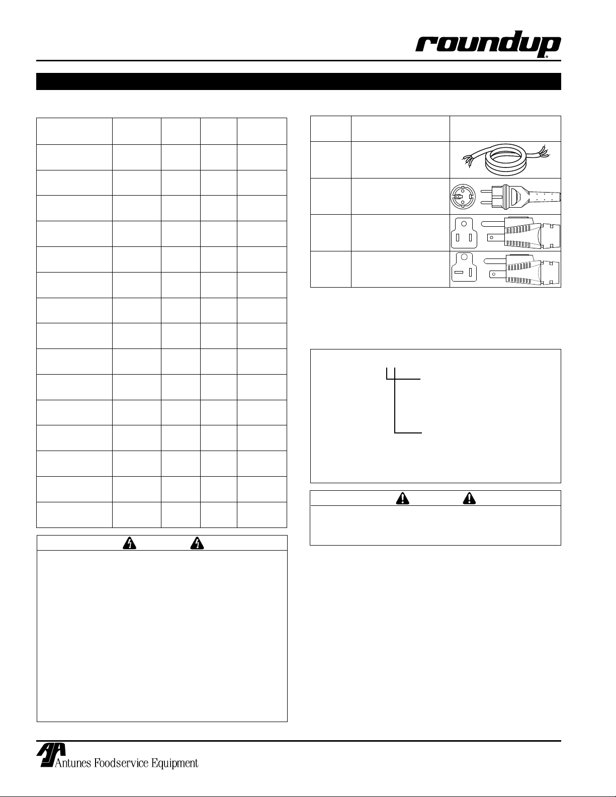
SPECIFICATIONS
Electrical Ratings
Model and
Mfg. #
DCH-100CF
9500500
DCH-120CF
9500510
DCH-120CT
9500512
DCH-200CT
9500520
DCH-220CT
9500530
DCH-220CT
9500531
DCH-220CT
9500532
DCH-220CT
9500534
DCH-220HC
9500536
DCH-220CT
9500538
DCH-300CT
9500540
DCH-320CT
9500550
DCH-320CT
9500552
DCH-320CT
9500554
DCH-320HC
9500556
ELECTRICAL SHOCK HAZARD. FAILURE TO
FOLLOW THE INSTRUCTIONS IN THIS MANUAL
COULD RESULT IN SERIOUS INJURY OR DEATH.
Voltage Watts Amps Hertz
120 1550 12.9 50/60
120 1550 12.9 50/60
120 1550 12.9 50/60
120 1800 15.0 50/60
120 1800 15.0 50/60
120 1800 15.0 50/60
120 1800 15.0 50/60
120 1800 15.0 50/60
220-240 2000 8.7 50/60
120 1800 15.0 50/60
120 1800 15.0 50/60
120 1800 15.0 50/60
120 1800 15.0 50/50
120 1800 15.0 50/60
220-240 2800 12.2 50/60
WARNING
Electrical Cord & Plug Configurations
Letter
Code*
C
H
(H)C*** CEE 7/7, 16 Amp.,
(C)F** 5-15P, 15 Amp., 120
(C)T** 5–20P, 20 Amp., 120
* Used in Model Designation
** Indicates that the plug comes with a Commercial Cord.
*** Indicates that the plug comes with a Harmonized Cord.
Model Designation
Description Configuration
Commercial Cord
Harmonized Cord
250 VAC (Assembly
Only).
VAC., Non – Locking
(Assembly Only).
VAC., Non – Locking
(Assembly Only).
DCH-100 XX
DCH-120
DCH-200
DCH-220
TYPE OF POWER CORD
H = HARMONIZED
C = COMMERCIAL
DCH-300
DCH-320
All electrical connections must be in accordance
with local electrical codes and any other applicable codes.
TYPE OF PLUG
C = CEE 7/7 Schuko
F = NEMA 5-15P
T = NEMA 5-20P
CAUTION
• Electrical ground is required on this appliance.
• Do not modify the power supply cord plug. If
it does not fit the outlet, have a proper outlet
installed by a qualified electrician.
• Do not use an extension cord with this appliance.
• Check with a qualified electrician if you are in
doubt as to whether the appliance is properly
grounded.
6
P/N 1010772 Rev. C 01/06
Page 7
DISPLAY CABINET HEATED
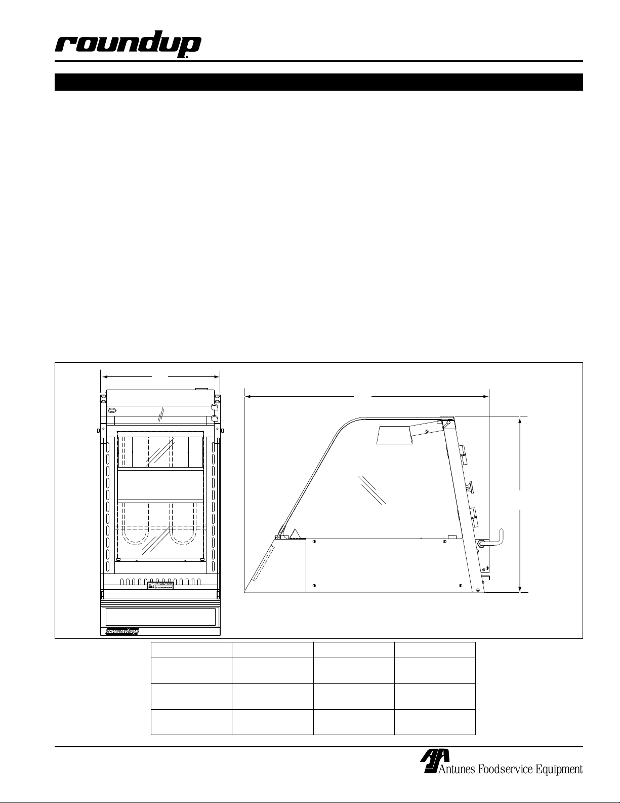
A
B
C
SPECIFICATIONS (continued)
Temperature Ranges
DCH-100: 150°-165°F (66°-74°C)
DCH-120: 100°-165°F (38°-74°C)
DCH-200: 150°-165°F (66°-74°C)
DCH-220: 100°-165°F (38°-74°C)
DCH-300: 150°-165°F (66°-74°C)
DCH-320: 100°-165°F (38°-74°C)
Dimensions
Capacities
DCH-100/DCH-120
• One 2-1/2” (63.5 mm) deep full size steam table pan.
• One water tray (some models) at 4 quarts (3.8 liters).
• One Crumb Tray (some models).
DCH-200/DCH-220
• Two 2-1/2” (63.5 mm) deep full size steam table pans.
• Two water trays (some models) at 4 quarts (3.8 liters)
each.
• One Crumb Tray (some models)
DCH-300/DCH-320
• Three 2-1/2” (63.5 mm) deep full size steam table
pans.
• Two water trays at 5 quarts (4.7 liters) each.
DCH-100
DCH-120
DCH-200
DCH-220
DCH-300
DCH-320
P/N 1010772 Rev. C 01/06
Model Dim. A Dim. B Dim. C
15-1/8”
(384 mm)
30-1/4”
(768 mm)
42-1/16”
(1068 mm)
7
30-1/4”
(768 mm)
30-1/4”
(768 mm)
30-1/4”
(768 mm)
22-13/32”
(569 mm)
22-13/32”
(569 mm)
22-13/32”
(569 mm)
Page 8
DISPLAY CABINET HEATED
THIS
UNIT
IS
DES
IG
NED
TO
O
PE
RATE
ON
1
2
0
V
O
LT
S
O
NLY
. AP
P
L
ICAT
IO
N
W
IT
H ANY
O
T
HER
VO
LT
AG
E
SUPP
LY
CO
M
PL
ETE
LY
VO
ID
S
AL
L
W
ARR
ANTY
.
PL
EAS
E
CH
ECK
Y
O
UR L
INE
VO
LT
AG
E
BEF
ORE
INS
ERTI
NG
TH
IS P
LUG
INT
O
THE
R
ECEP
TACL
E.
W
A
R
N
I
N
G
W
A
R
N
I
N
G
120 VAC
ONLY
T
H
I
S
A
P
P
L
I
A
N
C
E
M
U
S
T
B
E
E
A
R
T
H
E
D
(
G
R
O
U
N
D
E
D
)
T
H
I
S
A
P
P
L
I
A
N
C
E
M
U
S
T
B
E
E
A
R
T
H
E
D
(
G
R
O
U
N
D
E
D
)
THI
S
UN
IT
IS DE
SIG
NE
D T
O
O
PE
RATE
O
N 2
20
-
2
40
VO
L
TS
ONL
Y. A
PPL
ICA
T
IO
N
WIT
H
A
NY
O
T
HER
V
O
LT
AG
E S
UPPL
Y
CO
M
PL
ET
EL
Y VO
I
DS
AL
L
W
ARRANT
Y.
PL
EASE
CHE
CK
Y
O
UR L
INE
VO
L
TAG
E
BEF
O
RE
I
NS
ER
TING
THIS
P
L
UG I
NTO
T
HE
RECE
P
TACL
E.
W
A
R
N
I
N
G
W
A
R
N
I
N
G
220-240
VAC ONLY
T
H
I
S
A
P
P
L
IA
N
C
E
M
U
S
T
B
E
E
A
R
T
H
E
D
(
G
R
O
U
N
D
E
D
)
T
H
I
S
A
P
P
L
I
A
N
C
E
M
U
S
T
B
E
E
A
R
T
H
E
D
(
G
R
O
U
N
D
E
D
)
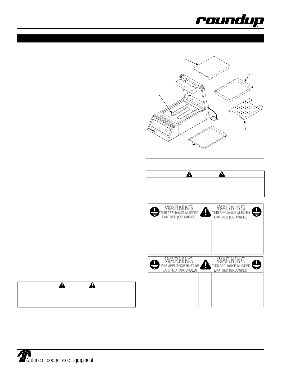
INSTALLATION
Unpacking
1. Remove unit and all packing materials from shipping carton.
2. Open the large box. Remove all packing materials and protective coverings from the unit and
parts.
NOTE: If any parts are missing, contact A.J
Antunes & Co. IMMEDIATELY at 1-877-392-7854 in
the U.S., or 630-784-1000 outside the U.S..
3. Wash all components in soap and water. Wipe
all surfaces of the unit with a hot damp cloth.
NOTE: Do not use a dripping wet cloth. Wring out
before use.
4. Install components in unit.
Equipment Setup
When placing the unit into service, pay attention to the
following guidelines:
• Make sure power to the unit is off and the unit is
at room temperature.
• Do not block or cover any openings on the unit.
Heating Element
Shield
Water Tray
(some models)
Heating
Element
Crumb Tray
(some models)
Do NOT use with Water
Diffuser
(Only used with
Water Tray)
Figure 1. Display Components (DCH-100 Shown)
WARNING
Be sure to follow all of the warnings and precautions listed in the Important Safety Information
section of this manual.
• Do not immerse cord or plug in water.
• Keep cord away from heated surfaces.
• Do not allow cord to hang over edge of table or
counter.
• Place unit on a sturdy, level table or work surface.
• Ensure that the line voltage corresponds to the
stated voltage on the unit specification label
located at the end of the power cord.
• Turn the Rocker Switch (power On/Off) to OFF.
Connect the unit to the power supply.
All electrical connections must be in accordance
with local electrical codes and any other applicable codes.
CAUTION
8
P/N 1010772 Rev. C 01/06
Page 9

TEMP
UP
TEMP
DOWN
TEMP
SCALE
F
C
O
O
T
E
M
P
U
P
T
E
M
P
D
O
W
N
T
E
M
P
S
C
A
L
E
F
C
O
O
W
A
T
T
S
S
E
R
I
A
L
N
O
.
C
A
R
O
L
S
T
R
E
A
M
I
L
6
0
1
8
8
M
F
G
.
N
O
.
V
O
L
T
S
1
8
0
K
E
H
O
E
B
O
U
L
E
V
A
R
D
A
.
J
.
A
N
T
U
N
E
S
&
C
O
.
H
Z
.
D
E
S
C
R
I
P
T
I
O
N
F
O
O
D
E
Q
U
I
P
M
E
N
T
D
I
V
I
S
I
O
N
M
O
D
E
L
N
O
.
C
I
T
Y
O
F
N
E
W
Y
O
R
K
A
C
C
E
P
T
E
D
F
O
R
U
S
E
M
E
A
1
0
9
6
E
D
C
H
3
2
0
C
T
D
I
S
P
C
A
B
I
N
E
T
H
E
A
T
E
D
5
0
/
6
0
1
2
0
~
9
5
0
0
5
5
0
X
X
X
X
X
X
X
X
1
8
0
0
D
E
P
A
R
T
M
E
N
T
O
F
B
U
I
L
D
I
N
G
S
OPERATING & PROGRAMMING
T
E
M
P
U
P
T
E
M
P
D
O
W
N
T
E
M
P
S
C
A
L
E
F
C
O
O
Operations and Programming
IMPORTANT: Models DCH-120/220/320 have an
adjustable temperature range of 100-165° F (38-74°
C). Since the temperature can be set below 150° F
(65° C), which is below the safe holding temperature for some foods, only NON-MEAT products
should be held in these units. Models DCH-100/
200/300 have an adjustable temperature range of
150-165° F (66-74° C).
NOTE: The Setpoint temperature is the desired
cabinet temperature setting. When the Temp UP
button is pressed and held (and provided that the
unit is up to temperature), the actual cabinet temperature is displayed. When the button is released,
the Setpoint temperature is displayed.
For units ONLY equipped with Water Tray(s) and
diffuser(s) (Figure 2):
DISPLAY CABINET HEATED
Figure 2. Filling Water Tray (DCH-100 shown)
NOTE: Back
of unit shown
Control Panel
Key Pad
• If a dry environment is desired, DO NOT add
water to the Water Trays. If a humid environment is desired, add water to the Water Trays as
shown in Figure 2. If more humidity is desired,
remove the Diffusers from the Water Trays.
NOTE: Fogging/Condensation of the glass may
occur if the Water Trays contain too much water
and/or the Diffusers are not present in the water
trays. Units equipped with a Crumb Tray (Figure 1)
are designed to operate WITHOUT water.
1. Turn the unit ON. The display will flash “LO” to
indicate that the unit is heating up. After 20-30
minutes (when the unit is up to temperature), the
display will show the setpoint temperature.
2. To adjust the setpoint temperature, press and
hold the Temp Up and Temp Down buttons until
the display begins to flash. Release the buttons.
Then, press the Temp Up or Temp Down buttons to raise or lower the setpoint temperature.
Release when the display shows the desired temperature.
3. To change the display from Fahrenheit to Celsius
and back, press and hold the Temp Scale button
(Figure 3) for 2-3 seconds and release.
Rocker Switch
(Power On/Off)
Figure 3. Controls
Figure 4. Loading Food (DCH-100 Shown)
4. Open the rear door(s) and place the serving table
pan(s) into the unit (Figure 4). Load the pan(s)
with the food product using tongs or similar utensil. Close the door(s).
P/N 1010772 Rev. C 01/06
9
Page 10

DISPLAY CABINET HEATED
MAINTENANCE
WARNING
Turn the unit off, disconnect the power source
and allow the unit to cool down before performing
any service or maintenance on the unit.
WARNING
Be sure to follow all of the warnings and precautions listed in the Important Safety Information
section of this manual.
WARNING
All glass surfaces must be cool before cleaning.
Once cool, wipe glass with a clean cloth. Do not
attempt to clean glass when hot or with cold towel
as shattering glass may occur.
Cleaning
The unit requires a minimum amount of maintenance.
To ensure proper operation, clean the unit at the end of
each serving day.
1. Turn off the unit, unplug the power cord from the
electrical outlet, and allow the unit to cool to room
temperature before proceeding.
HALOGEN QUARTZ BULB REPLACEMENT
1. Turn the Rocker Switch (power On/Off) to OFF.
2. Unplug the power cord from the electrical outlet
and allow the unit to cool to room temperature
before proceeding.
3. Gently, but firmly, press the lamp socket sideways
and remove the bulb (Figure 5).
4. Install a new 100 watt bulb while pressing the
socket sideways. Make sure bulb is fully seated
before releasing socket.
WARNING
Do not remove water pan or crumb tray while unit
is hot or personal injury may result.
2. Wash all components in soap and water. Wipe all
surfaces of the unit with a damp cloth.
NOTE: Do not use a dripping wet cloth. Wring the
cloth out before use.
3. Wash and dry all surfaces of the unit.
4. Install components in unit.
Parts Replacement
CAUTION
Do not handle halogen bulbs with fingers. Use a
tissue or clean cloth to handle halogen bulbs.
CAUTION
Use 100 Watt (Max.) quartz tungsten halogen lamp
(T4 Bulb/‘RSC’ Base) only. To reduce the risk of
electric shock when replacing bulbs, turn display
switch to OFF position.
Figure 5. Halogen Bulb Replacement
FRONT DISPLAY GRAPHICS AND BULB REPLACEMENT
1. Turn the Rocker Switch (Power On/Off) to OFF
2. Unplug the power cord from the electrical outlet
and allow the unit to cool to room temperature
before proceeding.
3. Using a screwdriver or similar flat bladed tool,
gently pry one side of the display panel assembly
from the unit (Figure 6), then remove the panel.
4. Remove bulb by gently turning it counterclockwise. Install a new 10 watt 120 volt bulb.
5. Install new graphics by removing the white diffuser plate and transparency holder. Replace
transparency and reinstall holder and plate.
REAR DOOR REPLACEMENT
DCH-100/120 Models
1. Turn the Rocker Switch (Power On/Off) to OFF.
2. Unplug the power cord from the electrical outlet
and allow the unit to cool to room temperature
before proceeding.
3. Open the rear door and lift off the Hinge Pins.
4. Place new door on Hinge Pins and close the
door.
10
P/N 1010772 Rev. C 01/06
Page 11

DISPLAY CABINET HEATED
T
E
M
P
U
P
T
E
M
P
D
O
W
N
T
E
M
P
S
C
A
L
E
F
C
O
O
MAINTENANCE
DCH-200/220/300/320 Models
1. Turn the Rocker Switch OFF, unplug the power
cord from the electrical outlet, and allow the unit
to cool to room temperature before proceeding.
2. Firmly grasp the sides of one glass door. Lift the
door up and out of the bottom track (Figure 7).
Repeat for the other door.
3. Place new door in the inside upper track. Push
up firmly and slide bottom of door into bottom
inside track. Install other door into outside tracks
the same way.
FRONT GLASS PANEL REPLACEMENT
CAUTION
Front glass panel replacement should be performed by two people to prevent damage to the
glass.
1. Turn the unit OFF, unplug the power cord from
the electrical outlet, and allow the unit to cool to
room temperature before proceeding.
2. Loosen the thumbscrew securing each Top Glass
Retainer Assembly. Slide the retainer up and to
the rear (Figure 8).
3. Tilt the Front Glass Panel Assembly forward on
the Hinge Plate and remove the panel from the
unit.
4. To reinstall, be sure the Front Glass Panel
Assembly is fully seated in the Hinge Plate.
Then, tilt the assembly fully towards the rear and
secure it to the Top Glass Retainer Assembly
using the thumb screws.
SIDE GLASS REPLACEMENT
1. Turn the unit OFF, unplug the power cord from
the electrical outlet, and allow the unit to cool to
room temperature before proceeding.
2. Remove the thumbscrews securing each Top
Glass Retainer Assembly. Slide the retainer up
and to the rear.
3. Tilt the Front Glass Panel Assembly forward on
the Hinge Plate and remove the assembly from
the unit.
4. Remove each Top Cap Assembly (Figure 8).
Next, lift the Side Glass Panel up and forward to
remove it from the glass clips.
6. To reinstall, position the Side Glass Panel into
glass clips. Push fully rearward and position the
Nylon Stoppers according to Figure 8. Reinstall
the front glass panel assembly (Figure 8).
(continued)
7. Secure with the Top Cap Assembly and Top
Glass Retainer Assembly using the thumbscrews.
NOTE: The Display Panel
Assembly is held in place
by magnetic strips. To
remove, carefully pry the
assembly from its place
using a flat-blade screw
driver or similar tool.
Figure 6. Display Lamp Replacement
Figure 7. Rear Door(s) Removal/Installation
DCH-200/220/300/320 Models.
Top Cap
Assy.
Nylon
Stopper
Hinge
Plate
Figure 8. Glass Panel (s) Replacement
-
Front Glass
Panel
Top Glass
Retainer
Assy.
Side Glass
Nylon
Stopper
P/N 1010772 Rev. C 01/06
11
Page 12

DISPLAY CABINET HEATED
MAINTENANCE (continued)
Technical Theory of Operation
When the Rocker Switch (power On/Off) is set to ON,
line voltage flows to the primary side of the Step Down
Transformer. The Transformer’s secondary side supplies 12-14 VAC to terminals T1 and T2 on the Control
Board.
Once powered, and provided that the Cabinet temperature is below the setpoint temperature, the Control
Board, in conjunction with a 100K ohm Thermistor, calls
for heat by supplying 15-20 VDC to terminals 3 (+) and
4 (-) on the Solid State Relay. Once powered, the Solid
State relay closes terminals 1 and 2, which allows line
voltage to flow to the heater(s).
As the Cabinet Temperature begins to increase, the
Thermistor monitors the Cabinet Temperature and
its ohms begin to decrease. Once the Cabinet temperature approaches the setpoint temperature, the
Thermistor’s ohms are relayed over to the Control
Board.
The Control Board receives the ohms and proceeds to
remove the 15 - 20 VDC to the Solid State Relay since
the Heating Circuit has now become satisfied. The
relay terminals 1 and 2 open and the heater(s) stop
heating. The heating circuit will cycle on and off as
needed. The control board has the ability to display
several codes (see the section titled Display Codes in
the Maintenance section of this manual).
On some models, the Heated air is circulated by one
or two blower motors, while other models do not use
blower motors. Some models use water trays while
other models use a crumb tray.
NOTE: Crumb Trays (Figure 1) must NOT contain
water.
When the Water Trays (Figure 1) are filled with water,
the heat radiated by the heaters cause the water
to evaporate, which gradually adds humidity to the
Cabinet (see the Operation section of this manual).
NOTE: Water Trays use a diffuser (Figure 1). The
purpose of a diffuser is to shield away excessive
heat. This will allow the water to evaporate at a
slower rate resulting in a reduction of humidity in
the cabinet. On 120 volt units, the front display
panel is illuminated by 4, 6, or 8 120V, 10 watt, candescent bulbs that are wired in parallel (see the
Wiring Diagram section of this manual for 120 Volt
units).
NOTE: The 220/240 volt units also use the 120 volt
bulbs, but the bulbs are wired in series and in two
bulb circuits (see the Wiring Diagram section of this
manual for 220/240 volt units).
The internal cabinet area is illuminated by 1 or 2 120
volt, 100 watt halogen bulb(s). On 120 volt units, each
halogen bulb is wired in series with a 10 ohm, 50 watt
resistor (see the Wiring Diagram section of this manual
for 120 volt units). The purpose of the resistors is to
allow for a voltage drop. The voltage drop allows the
halogen bulb’s brightness to be slightly reduced.
NOTE: On 220/240 units, the Halogen Bulbs and
Resistors are all wired in series with one another.
See the Wiring Diagram for 220/240 volt units.
12
P/N 1010772 Rev. C 01/06
Page 13

MAINTENANCE (continued)
TEMP
UP
TEMP
DOWN
TEMP
SCALE
F
C
O
O
TEMP
UP
TEMP
DOWN
TEMP
SCALE
F
C
O
O
TEMP
UP
TEMP
DOWN
TEMP
SCALE
F
C
O
O
TEMP
UP
TEMP
DOWN
TEMP
SCALE
F
C
O
O
TEMP
UP
TEMP
DOWN
TEMP
SCALE
F
C
O
O
Display Codes
This section describes the different display codes and
their meanings.
DISPLAY CABINET HEATED
“LO” flashes during the initial warm up period. The unit
continues to display this code until the unit reaches the
setpoint temperature. When the unit reaches the setpoint temperature, it displays the setpoint temperature.
This figure shows an example setpoint temperature of
150° F displayed on the console.
“HI” flashes if the actual cabinet temperature exceeds
the setpoint temperature or if the thermistor has shorted.
NOTE: The thermistor should be 100k ohm +/- 2% at
room temperature.
“OPEN” flashes if the thermistor is OPEN or disconnected. The unit will not call for heat.
NOTE: The thermistor should be 100k ohms +/- 2%
at room temperature.
“PO” In 120 VAC units, this code flashes if the supply
voltage is below 100 VAC or above 135 VAC. In 220/
240 VAC units, this code flashes if the supply voltage is
below 190 VAC or above 265 VAC.
NOTE: If voltage is within normal ranges, then the
Control Board is faulty.
P/N 1010772 Rev. C 01/06
To reset a unit in this state, the supply voltage must be
within acceptable limits and the unit must be turned off
for a few seconds and then turned back on.
13
Page 14

DISPLAY CABINET HEATED
TROUBLESHOOTING
WARNING
To avoid possible personal injury and/or damage to the unit, inspection, test and repair of electrical equipment should be performed by qualified service personnel. The unit should be unplugged when servicing.
Problem Possible Cause Corrective Action
No heat, no display, and the
power switch indicator light is
OFF.
No heat, no display, and the
power switch indicator light is
ON.
Display flashes “LO” and the
cabinet does not heat up.
Display flashes “HI” and the
cabinet does not heat up.
Display flashes “HI” and the
cabinet is very hot.
Display flashes “OPEN” and the
cabinet does not heat up.
Display flashes “PO” and the
cabinet does not heat up.
Product dries out quickly. Setpoint temperature is set too high. Lower the Setpoint temperature.
Display Cabinet glass is fogging
up and/or has condensation.
Halogen Bulb(s) do not light up. Bulb(s) burnt out. Replace bulb(s)
Front Display Graphics does not
light up.
Power cord is not plugged in. Plug the power cord into the appropriate outlet.
Circuit breaker is off or has been tripped. Reset circuit breaker, contact your maintenance person or
No power at receptacle. Contact your maintenance person or Authorized Service
Inoperable power cord.
Inoperable power switch.
Loose, burnt, broken wiring in the circuit.
Inoperable Transformer. Contact your maintenance person or Authorized Service
Inoperable Control Board.
Loose, burnt, broken wiring in circuit.
Inoperable Solid State Relay. Contact your maintenance person or Authorized Service
Inoperable Control Board.
Inoperable Heater(s).
Loose, burnt, broken wiring in circuit.
Inoperable Thermistor. Contact your maintenance person or Authorized Service
Inoperable control Board.
Solid State Relay contacts shorted closed. Contact your maintenance person or Authorized Service
Inoperable Control Board.
Thermistor is disconnected or open. Re-secure the Thermistor onto the Control Board. If this
Inoperable Control Board.
For 120 volt units, the supply voltage is below
100 VAC or above 135 VAC.
For 220/240 volt units, the supply voltage is
below 190 VAC or above 265 VAC.
Inoperable Control Board.
Incorrect wattage halogen bulb(s) being used. Use only 100 watt halogen bulb(s).
Water Tray(s) do not contain water or contain
insufficient water (for units equipped with
Water Trays only).
Water Tray(s) contain too much water and/or
the Water Tray Diffusers are not present (for
units equipped with Water Trays only).
Bulb(s) not seated properly into spring loaded
sockets.
Inoperable Resistor Assembly. Contact your maintenance person or Authorized Service
Loose, burnt, or broken wiring in Circuit.
Inoperable Bulb Sockets(s).
Bulb(s) burnt out. Replace Bulb(s).
Loose, burnt, or broken wiring in circuit. Contact your maintenance person or Authorized Service
Authorized Service Agency if it trips again.
Agency for service.
agency for service.
Agency for service.
Agency for service.
Agency for service.
problem persists, contact your maintenance person or
Authorized Service Agency for service.
Contact your maintenance person or Authorized Service
Agency for service.
Add water to the Water Trays(s) and/or remove the Water
Tray Diffuser(s).
Remove excess water from the Water Tray(s) and/or install
the Water Tray Diffuser(s).
Remove and reinstall bulb(s) so that the ends snap into the
socket(s).
Agency for service.
Agency for service.
14
P/N 1010772 Rev. C 01/06
Page 15

DISPLAY CABINET HEATED
47
18
60
50
61
23
22
50
60
59
19
47
27
47
30
28
32
31
33
35
20
12
55
16
49
53
50
49
15
17
11
13
40
44
52
2
42
43
52
3
1
55
52
4
9
9
10
5
6
58
7
57
63
21
48
37
64
36
62
8
45
51
34
14
65
56
25
50
39
38
65
26
66
67
REPLACEMENT PARTS – DCH-100/120
P/N 1010772 Rev. C 01/06
15
Page 16

DISPLAY CABINET HEATED
REPLACEMENT PARTS – DCH-100/120
Item Part Description Qty.
No.
1 7000365 Front Glass Panel Assy. 1
2 0021057 Inner Lamp Housing Weldment 1
3 0011107 Resistor Assy. 1
4 0503046 Housing, Lamp 1
5 0011102 Rear Door Assy. (Incl. #6, 7, 57, 58) 1
6 2110139 Hinge, Lift-Off 2
7 2100145 Knob, Cover 1
8 0503294 Crumb Tray (some models) 1
9 0503038 Water Tray (some models) 1
10 0502172 Heat Shield 1
11 0021315 Control Panel Weldment 1
12 7000346 Temperature Control Display,
150°F-165°F (66°C-74°C) DCH-100 1
7000345 Temperature Control Display,
100°-165°F (38°-74°C), DCH-120 1
13 4010151 Rocker Switch, Power On/Off 120 VAC 1
14 7000645 Side Glass Replacement Kit 1
15 0503948 Heat Sink Assy. 2
16 4010199 Transformer, 120V/12V 1
17 7000652 Relay, Solid State 1
18 7000136 Terminal Block, 3-Pole 1
(Incl. #47 & 60)
19 4060341 Terminal Block, 8-Pole 1
20 0504070 Retainer, Glass (see Note 1) 2
21 0011718 Top Cap Assy., LH** (see Note 1) 1
0011717 Top Cap Assy., RH** (see Note 1) 1
22 0502866 Cover, Lamp Housing Bracket 1
23 0502865 Bracket, Lamp 1
25 0700463 Power Cord w/Plug, NEMA 5-15P 1
26 020K110 Gasket Kit, Bottom 1
27 0503990 Lamp, Bulkhead (Mfg# 9500512 only) 1
0503275 Lamp, Bulkhead 1
28 4060360 Candelabra Lamp Holder 4
30 4060359 Lamp, 120V, 10 Watt 4
31 0900216 Diffuser Panel (White) 1
32 2070120 Nipple, 1/8 NPT x 3/8 1
* Only available in packages of 1
** LH/RH is determined by viewing front of curved glass panel.
0.
Item Part Description Qty.
No.
33 0900215 Display Panel (clear) 1
34 0021056 Display Frame Weldment 1
0021321 Display Frame Weldment 1
(MFG. # 9500512 only)
35 0503033 Display Frame 1
36 0200202 Magnetic Strip 1
37 5040036 Base Hinge Assy. 1
38 4030305 Heating Element, 120V 1400 Watts 1
39 7000369 Thermistor Replacement Kit 1
40 0503037 Duct, Access Cover 1
42 4060252 Bulb, Quartz Halogen, 100 Watt 1
43 4060189 Bulb, Holder, Quartz 2
44 0800316 Guard, Lamp 1
45 040K251 Strain Relief w/Locknut 1
47 306P101* Nut, Hex, #6-32, SS 1
48 306P105* Screw, #6-32 x 1/2, SS 1
49 306P130* Nut, Hex, KEPS, #6-32 1
50 308P103* Screw, #8-32 x 1/4 6
51 308P124* Screw, #8-32 x 1/2, One-Way 1
52 308P127* Screw, #8-32 x 5/16, SS 1
53 308P143* Nut, Hex, KEPS, #8-32 1
54 308P144* Screw, #8-32 x 1/4, #6 Head 2
55 308P159* Thumbscrew, #8-32 x 11/32 1
56 310P146* Nut, Hex, KEPS, #10-32 1
57 310P110* Screw, #10-32 x 1/2, SS 4
58 310P123* Screw, #10-24 x 1/2, SS 1
59 040P111* Snap Bushing 2
60 306P123* Screw, #6-32 x 7/8 2
61 308P151* Screw, #8-32 x 5/16” 1
62 0503044 Diffuser, Water Tray (some models) 1
63 400K123 Blower Kit 120V (some models) 1
Incudes #66
64 0501946 Blower Grill (some models) 1
65 2180179 Side Glass Nylon Stopper 2
(see Note 1)
66 7000174 Blower Cage Bearing/Grommet Kit 1
67 7000106 Display Rack (Optional) 1
NOTE: If the existing 2 Top Glass Retainers (item #20)
ARE NOT rubber coated. It is recommended that you
replace them along with the 2 Top Cap Assembly (item
#21) with Glass Hardware Kit #7000368.
This kit consists of:
• Two (2) rubber coated Glass Retainer (P/N 0504070)
• One (1) Top Cap Assembly (RH) (P/N 0011717)
• One (1) Top Cap Assembly (LH) (P/N 0011718)
• Two (2) Nylon Side Glass Stoppers
(P/N 2180179)
• Two (2) Thumbscrews (P/N 3080159)
• Installation Instructions
16
P/N 1010772 Rev. C 01/06
Page 17

DISPLAY CABINET HEATED
53
64
46
45
53
48
54
25
26
20
58
21
24
50
18
68
12
16
56
52
15
17
11
13
35
42
43
55
41
10
58
55
50
6
4
55
40
44
2
3
7
19
52
67
31
32
33
34
30
29
68
62
14
5
22
59
1
39
38
70
37
36
69
27
71a
67
23
71b
66
65
9
REPLACEMENT PARTS – DCH-200/220
P/N 1010772 Rev. C 01/06
17
Page 18

DISPLAY CABINET HEATED
REPLACEMENT PARTS – DCH-200/220 (continued)
Item Part Description Qty. Qty. Qty.
No.
120 V 120 V 230 V
1 7000366 Front Glass Panel Assy. 1 1 1
2 0020675 Inner Lamp Housing Weldment 1 1 1
3 0010706 Resistor Assy., 120V 1 1 0010644 Resistor Assy., 220V - - 1
4 0502895 Housing, Lamp - - 1
5 9020459 Display Rack (Optional) - - 6 7000443 Sliding Door Assy., Clear Glass 1 1 1
7000445 Sliding Door Assy., Mirrored, Glass (optional) - - 7 0501820 Support, Center Pan 1 1 1
9 0503293 Crumb Tray (some models) - - 10 0503283 Heat Shield 1 1 1
11 0021453 Control Panel Weldment 1 1 1
12 7000346 Temperature Control Display,
150°F-165°F (66°C-74°C) DCH-200 1 - 7000345 Temperature Control Display,
100°-165°F (38°-74°C), DCH-220 - 1 1
13 4010151 Rocker Switch, Power On/Off (120V) 1 1 4010137 Rocker Switch, Power On/Off (250V) - - 1
14 7000645 Side Glass Replacement Kit 2 2 2
15 0020702 Heat Sink Assy. 1 1 1
16 4010199 Transformer, 120V/12V 1 1 4010187 Transformer, 240V12V - - 1
17 7000652 Relay, solid state. 1 1 1
18 7000136 Terminal Block, 3 Pole (incl. #50 & 67) 1 1 1
19 4060341 Terminal Block, 8 Pole 2 2 2
20 0504070 Retainer, Glass (see Note 1) 2 2 2
21 0011718 Top Cap Assy., LH** (see Note 1) 1 1 1
0011717 Top Cap Assy., RH** (see Note 1) 1 1 1
22 2100183 Door Track, Upper 1 1 1
23 2100184 Door Track, Lower 1 1 1
24 0501946 Grill, Blower (some models) 1 1 25 0700451 Power Cord w/Plug, NEMA 5-20P 120V 1 1 0700453 Power Cord w/Plug, CEE 7/7 240V - - 1
26 020K107 Gasket Kit, Bottom 1 1 1
27 0503291 Lamp, Bulkhead (some models) 1 1 0503771 Lamp, Bulkhead (some models) - 1 1
29 4060360 Candelabra Lamp Holder 6 6 6
30 4060359 Lamp, 120 v/10 Watt 6 6 6
31 0900151 Diffuser Panel (white) 1 1 1
32 0900173 Transparency Holder 1 1 1
33 0900150 Display Panel (black outline) Optional 1 1 0900180 Display Panel (clear) Optional - - 0900244 Display Panel (blue outline) - 1 1
34 0501797 Display Frame 1 1 1
35 400K123 Blower Motor, 120 Volt (some models) Incl #69 1 1 36 0200154 Magnetic Strip 2 2 2
37 5040027 Base Hinge Assy. 1 1 1
38 4030324 Heating Element, 120V, 1400 Watts 1 1 4030325 Heating Element, 230V, 1650 Watts - - 1
* Only available in packages of 10
** LH/RH is determined by viewing front of curved glass panel.
DCH-200 DCH-220 DCH-220
18
P/N 1010772 Rev. C 01/06
Page 19

DISPLAY CABINET HEATED
REPLACEMENT PARTS – DCH-200/220 (continued)
Item Part Description Qty. Qty. Qty.
No.
120 Volt 120 Volt 230 Volt
39 7000369 Thermistor Kit 1 1 1
40 0501806 Duct, Access Cover 1 - 41 0502555 Heat Deflector (some models) 1 - 42 4060252 Bulb, Quartz Halogen, 100 Watt 2 2 2
43 4060189 Bulb Holder, Quartz 4 4 4
44 0800224 Guard, Lamp 1 1 1
45 0502866 Cover, Lamp Housing Bracket 2 2 2
46 0502865 Bracket, Lamp Housing 2 2 2
48 040K251* Strain Relief w/Locknut 1 1 1
50 306P101* Nut, Hex, #6-32, SS 1 1 1
51 306P105* Screw, #6-32 x 1/2, SS 1 1 1
52 306P130* Nut, Hex, KEPS, #6-32 1 1 1
53 308P103* Screw, #8-32 x 1/4 6 6 6
54 308P124* Screw, #8-32 x 1/2, One-Way 1 1 1
55 308P127* Screw, #8-32 x 5/16, SS 1 1 1
56 308P143* Nut, Hex, KEPS, #8-32 1 1 1
57 308P144* Screw, #8-32 x 1/4 2 2 2
58 308P159* Thumbscrew, #8-32 x 11/32 1 1 1
59 310P146* Nut, Hex, KEPS, #10-32 1 1 1
60 310P110* Screw, #10-32 x 1/2, SS 4 4 4
61 310P123* Screw, #10-24 x 1/2, SS 1 1 1
62 040P111* Snap Bushing 2 2 2
63 308P105* Screw, #8-32 x 1/2, SS 2 2 2
64 308P151* Screw #8-32 x 5/16” 1 1 1
65 0503280 Diffuser, Water Tray (some models) - - 66 0503279 Water Tray (some models) - - 67 2180179 Side Glass Nylon Stopper 2 2 2
68 306P123* Screw, #6-32 x 7/8” 1 1 1
69 7000174 Blower Cage Bearing/Grommet Kit 1 1 1
70 213K103 Full Size Pan 2-1/2” deep - Non-perforated (optional) - - 71a 002K853 Pan Adapter Insert (optional) - - (accomodates two optional 4” deep full size pans)
71b 0021348 Pan Adapter Insert - Sloped Version (Optional) - - -
DCH-200 DCH-220 DCH-220
* Only available in packages of 10
** LH/RH is determined by viewing front of curved glass panel.
NOTE 1: If the existing 2 Top Glass Retainers (item #20) ARE NOT rubber coated, it is recommended that you replace
them along with the 2 Top Cap Assemblies (item #21) with Glass Hardware Kit #7000368. This kit consists of:
• 2 rubber coated Glass Retainers (P/N 0504070)
• 1 Top Cap Assembly (RH) (P/N 0011717)
• 1 Top Cap Assembly (LH) (P/N 0011718)
• 2 Nylon Slide Side Glass Stoppers (P/N 2180179)
• 2 Thumbscrews (P/N 3080159)
• Installation Instructions (P/N 1010828)
P/N 1010772 Rev. C 01/06
19
Page 20

DISPLAY CABINET HEATED
53
46
45
12
16
56
52
15
17
11
13
42
43
55
41
9
69
58
6
4
55
40
44
2
3
7
5
1
39
70
23
7
20
58
22
24
66
53
48
54
25
50
18
65
34
31
32
33
29
30
50
37
66
36
35
52
19
35
52
71
71
14
21
34
55
67a
67b
10
65
62
38
8
REPLACEMENT PARTS – DCH-300/320
20
P/N 1010772 Rev. C 01/06
Page 21

DISPLAY CABINET HEATED
REPLACEMENT PARTS – DCH-300/320 (continued)
Item Part Description Qty.
No.
1 7000367 Front Glass Assy. 1
2 0020676 Inner Lamp Housing Weldment 1
3 0010706 Resistor Assembly - 120V 1
0010644 Resistor Assembly - 230V 1
4 0502850 Housing, Lamp 1
5 9020469 Display Rack (optional) 1
6 7000444 Sliding Door Assembly 2
7 0501869 Support, Center Pan 2
8 0504354 Crumb Tray 1
(Mfg No. 9500554 & 556 Only)
9 0501866 Water Tray 2
Except for Mfg No. 9500554 & 556)
10 0502172 Shield, Heat 3
11 0021317 Control Panel Weldment 1
12 7000346 Temperature Control Display,
150°F-165°F (66°C-74°C) 1
7000345 Temperature Control Display,
100°-165°F (38°-74°C) 1
13 4010151 Switch, Rocker 25A-125V 1
4010137 Switch, Rocker 25A-250V 1
14 0900143 Glass, Side 2
15 0020702 Heat Sink Assy. 1
16 4010199 Transformer 120VAC/12VAC 1
4010187 Transformer 230VAC/12VAC 1
17 7000652 Relay, Solid State 1
18 7000136 Terminal Block-3 Pole (Incl. #50 & 65) 1
19 4060341 Terminal Block-8 Pole 2
20 0504070 Glass Retainer (see Note 1)
21 0011717 Top Cap Assembly** RH (see Note 1) 1
0011718 Top Cap Assembly** LH (see Note 1) 1
22 2100185 Upper Door Track 1
23 2100186 Lower Door Track 1
24 0501946 Grill, Blower 1
25 0700451 Power Cord w/Plug, 1
NEMA 5-20P 120 V
0700453 Power Cord w/Plug, CEE 7/7 1
26 020K108* Gasket Kit, Bottom 1
27 0503976 Lamp, Bulkhead 1
29 4060360 Lampholder 8
30 4060359 Lamp, Night - 120V, 10 Watts 8
31 0900152 Display Panel (Black Outline) 1
0900181 Display Panel (Clear) 1
* Only available in packages of 10
** LH/RH is determined by viewing front of curved glass panel.
NOTE 1: If the existing 2 Top Glass Retainers (item #20) ARE NOT rubber coated, it is recommended that you replace
them along with the 2 Top Cap Assemblies (item #21) with Glass Hardware Kit #7000368. This kit consists of:
• 2 rubber coated Glass Retainers (P/N 0504070)
• 1 Top Cap Assembly (RH) (P/N 0011717)
• 1 Top Cap Assembly (LH) (P/N 0011718)
• 2 Nylon Slide Side Glass Stoppers (P/N 2180179)
• 2 Thumbscrews (P/N 3080159)
• Installation Instructions (P/N 1010828)
Item Part Description Qty.
No.
32 0900174 Transparency Holder 1
33 0900153 Diffuser Panel (white) 1
34 0501860 Frame, Display 1
35 400K123 Motor, Blower 120V Incl. #71 2
(Except Mfg. No. 9500554 & 556)
36 0200155 Magnetic Strip 2
37 5040028 Base Hinge Assy. 1
38 4030304 Heating Element, 120V, 500 Watts 3
4030239 Heating Element 230 Volts 825 Watts 3
39 7000369 Thermistor Kit 1
40 0501865 Duct Access Cover 1
41 0502556 Deflector, Heat 1
42 4060252 Bulb-Quartz Halogen 100W 2
43 4060189 Bulbholder, Quartz 4
44 0800229 Guard, Lamp 1
45 0502866 Cover, Lamp Bracket 2
48 040K251 Strain Relief Kit. 1
46 0502865 Bracket, Lamp Housing 2
50 306P101* Nut, Hex, #6-32, SS 1
51 306P105* Screw, #6-32 x 1/2, SS 1
52 306P130* Nut, Hex, KEPS, #6-32 1
53 308P103* Screw, #8-32 x 1/4, 6
54 308P124* Screw, #8-32 x 1/2, 1
55 308P127* Screw, #8-32 x 5/16, SS 1
56 308P143* Nut, Hex, KEPS, #8-32 1
57 308P144* Screw, #8-32 x 1/4, #6 Head 2
58 308P159* Thumbscrew, #8-32 x 11/32 1
59 310P146* Nut, Hex, KEPS, #10-32 1
60 310P110* Screw, #10-32 x 1/2, SS 4
61 310P123* Screw, #10-24 x 1/2, SS 1
62 040P111* Snap Bushing 2
63 308P105* Screw, #8-32 x 1/2, SS 2
64 308P151* Screw, #8-32 x 5/16” 1
65 306P123* Screw, #6-32 x 7/8” 1
66 2180179 Side Glass Nylon Stopper 1
67a 0021478 Pan Adapter Insert (Optional) 1
(slope version)
67b 002K897 Pan Adapter Insert (Optional) 1
(non-slope version)
69 0501966 Diffuser, Water Tray 2
70 213K103 Full size pan 2-1/2” deep (optional) 1
71 7000174 Blower Cage Bearing & Grommet Kit 1
(Except Mfg. No. 9500554 & 556)
P/N 1010772 Rev. C 01/06
21
Page 22

DISPLAY CABINET HEATED
#WHT
*WHT
#WHT
*WHT
*BLK
SWITCH
POWER
GRN-YEL
GRN
WHT/BLU
BLK/BRN
THERMISTOR
HEATER
QUARTZ
LAMP
#BLK
#BLK
YEL
YEL
YEL
YEL
RED
BLK
WHT
BLK
TRANSFORMER
#WHT
*BLK
4
3
S.S.
RELAY
1
2
*BLK
TEMPERATURE
CONTROLLER
T5
T1
T2
T3
T4
T9
T7
T8
BLOWER
M
RESISTOR
#BLK
WHT
WHT
BLK
BLK
WHT
BLK
WHT
DISPLAY LAMPS
BLK
#BLK
*GRN
BLOCK #1
TERMINAL
GND
CORD
POWER
+
-
*14 GA. TFE 200°
#18 GA. TFE 200°
TERMINAL
BLOCK #2
#WHT
*WHT
#WHT
*WHT
*BLK
SWITCH
POWER
GRN-YEL
GRN
WHT/BLU
BLK/BRN
WHT
BLK
WHT
BLK
BLK
WHT
WHT
DISPLAY LAMPS
THERMISTOR
BLK
HEATER
QUARTZ
LAMP
#BLK
#BLK
YEL
YEL
YEL
YEL
RED
BLK
WHT
BLK
TRANSFORMER
#WHT
*BLK
4
3
S.S.
RELAY
1
2
*BLK
WHT
WHT
BLK
BLK
TEMPERATURE
CONTROLLER
T5
T1
T2
T3
T4
T9
T7
T8
#WHT
#BLK
BLOWER
M
RESISTOR
RESISTOR
#BLK
#BLK
(OPTIONAL)
BLOCKS
TERMINAL
*GRN
BLOCK #1
TERMINAL
GND
CORD
POWER
+
-
*14 GA. TFE 200°
#18 GA. TFE 200°
BLOCKS
TERMINAL
1 2
5
4
#WHT
*WHT
#WHT
*WHT
*BLK
SWITCH
POWER
GRN-YEL
GRN
WHT/BLU
BLK/BRN
WHT
BLK
WHT
BLK
WHT
BLK
DISPLAY LAMPS
THERMISTOR
HEATER
QUARTZ
LAMP
#BLK
#BLK
YEL
YEL
YEL
YEL
RED
BLK
WHT
BLK
TRANSFORMER
#WHT
*BLK
4
3
S.S.
RELAY
1
2
*BLK
WHT
WHT
BLK
BLK
TEMPERATURE
CONTROLLER
T5
T1
T2
T3
T4
T9
T7
T8
RESISTOR
RESISTOR
#BLK
WHT
BLK
BLK
BLK
LAMP
QUARTZ
WHT
BLOCKS
TERMINAL
*GRN
BLOCK #1
TERMINAL
GND
CORD
POWER
+
-
*14 GA. TFE 200°
#18 GA. TFE 200°
BLOCKS
TERMINAL
#WHT
*WHT
#WHT
BLOCKS
TERMINAL
*WHT
*BLK
*GRN
SWITCH
POWER
BLOCK #1
TERMINAL
GND
GRN-YEL
GRN
WHT/BLU
BLK/BRN
CORD
POWER
BLK
WHT
BLK
WHT
WHT
BLK
BLK
DISPLAY LAMPS
THERMISTOR
WHT
HEATER #1
QUARTZ
LAMP
#BLK
#BLK
YEL
YEL
YEL
YEL
RED
BLK
WHT
BLK
TRANSFORMER
#WHT
*BLK
4
3
S.S.
RELAY
1
2
*BLK
*14 GA. TFE 200°
#18 GA. TFE 200°
BLK
BLK
WHT
WHT
TEMPERATURE
CONTROLLER
T5
T1
T2
T3
T4
T9
T7
T8
#BLK
#WHT
BLOWER Optional
M
BLOCKS
TERMINAL
RESISTOR
RESISTOR
BLK
BLK
BLOWER Optional
M
BLK
BLK
WHT
HEATER #2
HEATER #3
*WHT
*BLK
*BLK
*WHT
+
-
WIRING DIAGRAMS
DCH-100/120 (120 Volt Units) DCH-200/220 (120 Volt Units)
DCH-220 (220/240 Volt Units) DCH-300/320 (120 Volt Units)
22
P/N 1010772 Rev. C 01/06
Page 23

DISPLAY CABINET HEATED
#WHT
*WHT
#WHT
*WHT
*BLK
SWITCH
POWER
GRN-YEL
GRN
WHT/BLU
BLK/BRN
DISPLAY LAMPS
THERMISTOR
HEATER
QUARTZ
LAMP
#BLK
#BLK
YEL
YEL
YEL
YEL
RED
BLK
WHT
BLK
TRANSFORMER
#WHT
*BLK
4
3
S.S.
RELAY
1
2
*BLK
TEMPERATURE
CONTROLLER
T5
T1
T2
T3
T4
T9
T7
T8
RESISTOR
RESISTOR
#BLK
LAMP
QUARTZ
WHT
BLK
WHT
WHT
BLK
BLK
WHT
BLK
BLK
BLK
WHT
WHT
BLK
WHT
WHT
BLK
BLK
WHT
BLK
BLK
BLK
WHT
*GRN
BLOCK #1
TERMINAL
GND
CORD
POWER
*14 GA. TFE 200°
#18 GA. TFE 200°
BLOCKS
TERMINAL
WIRING DIAGRAMS (continued)
DCH-320 (230 Volt Units)
P/N 1010772 Rev. C 01/06
23
Page 24

LIMITED WARRANTY
A.J. Antunes & Co.
Headquarters/Manufacturing
180 Kehoe Boulevard
Carol Stream, Illinois 60188
USA
Phone (630) 784-1000
Toll Free (800) 253-2991
Fax: (630) 784-1650
Antunes Equipment
Manufacturing (Suzhou) Ltd.,
9 Hou Ju Road, Building #24,
S&T Park, SND
Suzhou, Jiangsu, China 215011
Phone: 86-512-6841-3637
Fax: 86-512-6841-3907
www.ajantunes.com
Equipment manufactured by A.J. Antunes & Co. Foodservice Equipment has been constructed of the finest materials available and
manufactured to high quality standards. These units are warranted to be free from mechanical and electrical defects for a period
of one year from date of purchase or 18 months from shipment from factory, whichever occurs first, under normal use and service,
and when installed in accordance with manufacturer’s recommendations.
To insure continued proper operation of the units, follow the maintenance procedure outlined in the Owner’s Manual.
1. This warranty does not cover cost of installation, defects caused by improper storage or handling prior to placing of the Equipment. This
warranty does not include overtime charges or work done by unauthorized service agencies or personnel. This warranty does not cover
normal maintenance, calibration, or regular adjustments as specified in operating and maintenance instructions of this manual, and/or
labor involved in moving adjacent objects to gain access to the Equipment. This warranty does not cover consumable items such as
gaskets and light bulbs, nor does it cover water contaminant problems such as foreign material in water lines or inside solenoid valves.
It does not cover water pressure problems or failures resulting from improper/incorrect voltage supply.
For the first 90 (ninety) days after installation (in the U.S. ONLY), the unit will be repaired in-store (subject to the terms of the limited
warranty) by our Authorized Service Agency at no charge for parts and non-overtime labor. Travel time and mileage charges in excess
of 2 hours (100 miles roundtrip) from the nearest Authorized Service Agency is not covered under this warranty and is the responsibility
of the end user.
2. Roundup reserves the right to make changes in design or add any improvements on any product. The right is always reserved to modify
equipment because of factors beyond our control and government regulations. Changes to update equipment do not constitute a warranty charge.
3.
If shipment is damaged in transit, the purchaser should make a claim directly upon the carrier. Careful inspection should be made of the shipment as soon as it arrives and visible damage should be noted upon the carrier’s receipt. Damage should be reported to the carrier. This
damage is not covered under this warranty.
4. Warranty charges do not include freight or foreign, excise, municipal or other sales or use taxes. All such freight and taxes are the
responsibility of the purchaser.
5. THIS WARRANTY IS EXCLUSIVE AND IS IN LIEU OF ALL OTHER WARRANTIES, EXPRESSED OR IMPLIED, INCLUDING ANY
IMPLIED WARRANTY OR MERCHANTABILITY OR FITNESS FOR A PARTICULAR PURPOSE, EACH OF WHICH IS HEREBY
EXPRESSLY DISCLAIMED. THE REMEDIES DESCRIBED ABOVE ARE EXCLUSIVE AND IN NO EVENT SHALL ROUNDUP BE
LIABLE FOR SPECIAL CONSEQUENTIAL OR INCIDENTAL DAMAGES FOR THE BREACH OR DELAY IN PERFORMANCE OF THIS
WARRANTY.
 Loading...