

Page 1
A N T H E M P R E 1 P O P E R A T I N G M A N U A L
2 7 90 B R IG H T O N R O A D , O A K V I L L E , O N T A R I O, C A N AD A L 6 H 5 T 4 T E L : ( 9 0 5 ) 8 2 9 - 3 8 3 8 F A X : ( 9 0 5 ) 8 2 9 - 3 0 3 3
S o n i c F r o n t i e r s c a n b e r e a c h e d 9 : 0 0 a m t o 6 : 0 0 p m ( E . S . T . ) o r 2 4 h o u r s a d a y b y f a c s i m i l e
E - m a i l S F I @ s o n i c f r o n t i e r s . c o m W o r l d W i d e W e b S i t e h t t p : / / w w w . s o n i c f r o n t i e r s . c o m
D E S I G N E D A N D M A N U F A C T U R E D B Y S O N I C F R O N T I E R S I N C O R P O R A T E D
Page 2
A B
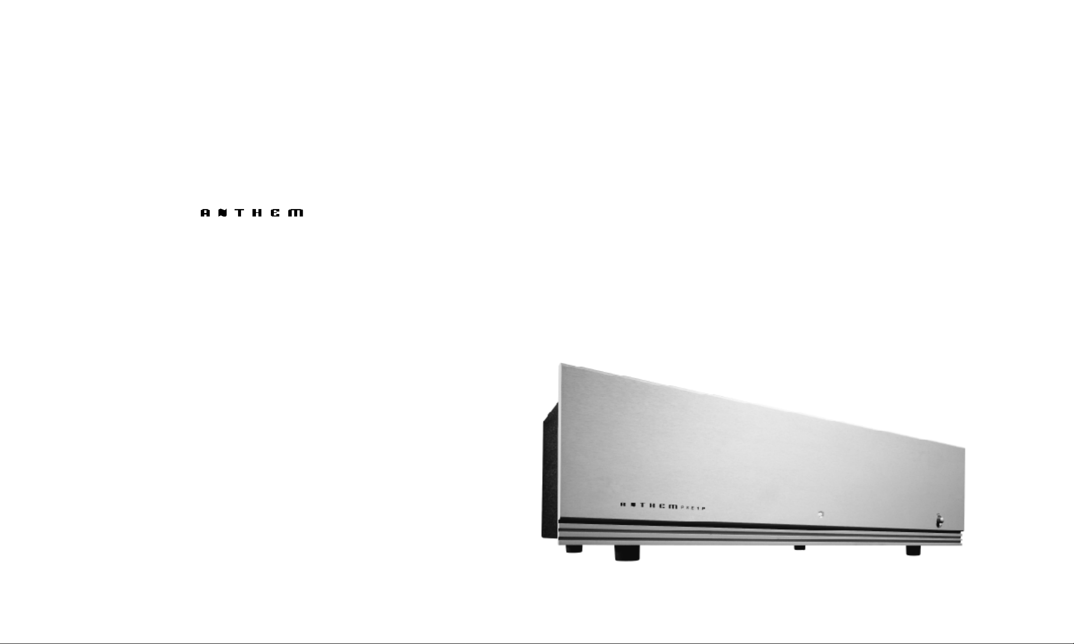
We at Sonic Frontiers hope you will derive many years
of listening pleasure with your new Anthem Pre 1P. This
Operating Manual contains important information regarding the operation and care of the Pre 1P. Be sure to read
this manual carefully and follow these instructions in order
to keep it performing and sounding its best. Please contact Sonic Frontiers if you have any questions, a Customer
Service Representative will be pleased to assist you.
10/23/97
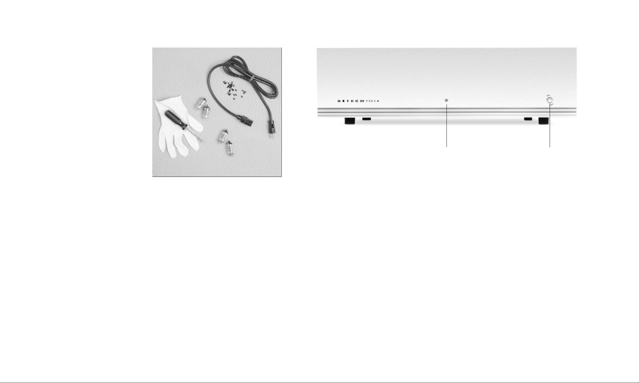
W H AT ’ S I N T H E B O X ?
In addition to the Pre 1P, its covers, and the operating
manual you are presently reading (with associated inserts
and warranty card), there are a few more items to take
inventory of before steps are taken to make the Anthem
Pre 1P operational.
These items are:
• one each selected pair of 6922/6DJ8 and
12AT7/ECC81 tubes totaling 4*.
• a glove for handling the tubes
• a detachable AC power cord
• 18 screws
• 1 Philips #1 screwdriver
After completing an inventory of these items, proceed
to the next steps.
*These tubes are carefully measured and matched in
pairs. Take extra care to keep the pairs from being mixed
and mismatched which would degrade performance.
C O N T R O L F U N C T I O N S
A PR EAMPLIFIER L ED
This Light Emitting Diode illuminates when power is
applied and the Pre 1P is turned on via the ON-OFF
Button (B)
B ON-OFF BUTTON
When in the ON position (button depressed), all power
supplies within the preamplifier are initiated. A delay of
approximately 45 seconds is required for the power
supplies to stabilize. After the 45 second delay, the
muting relay will engage, and the phono stage is
operational. When in the OFF position (not depressed),
the Pre 1P is OFF.
Page 3

WARNING- DISCONNECT THE AC
DETACHABLE POWER CORD FROM THE
Pre 1P AND WAIT 5 MINUTES BEFORE
REMOVING COVER, TUBES OR FUSE.
3. Noting the location of the tube sockets in the top view
photo (Figure 2) or directly on the Printed Circuit Board,
inspect the tubes for corresponding labels and markings.
Once locations are mapped, take a tube and inspect the
pins, noting the larger space between two of the pins
S E T T I N G U P
(see Figure 1). This space will match with the socket.
Insert each tube into the appropriate tube socket, mak-
The Pre 1P comes with four tubes, as follows:
ing sure all pins and pin holes are aligned. Do not force
the tubes into the sockets. “Rock” the tubes gently while
2-69 22/6DJ 8 (V1, V3) AND 2 12AT7/ ECC81(V2, V4)
pushing slowly until each tube is firmly seated.
These tubes were chosen for their reliability and extremely
low noise. The amplifier topology used in the Pre 1P delivers exceptional performance using the factory selected
low noise tubes, heightening dynamics and providing a
natural tonal balance.
C
D
F
INSERTION OF THE TU BES
Note the larger space
between two of the pins and
holes for proper alignment
of tube and socket.
1. Using the screwdriver supplied, remove the cover of
E
the Pre 1P. For your convenience, only four of the screws
are installed at the factory.
Figure 1
2. When handling the tubes, it is recommended that the
cotton gloves provided be worn to prevent skin oils from
depositing on the glass surface.
C D E TACHABLE IEC AC POWER CORD SOCKET
Plug the Detachable Power Cord into this socket (see
Figure 4). The Pre 1P is factory set for the correct
operating voltage for the area in which it is sold (see
shipping box for voltage setting). If a different operating voltage is required, please contact an authorized
Sonic Frontiers or Anthem dealer, distributor or the
factory directly.
D O U T P U T S
These outputs connect to the unbalanced line level
inputs of other units such as preamplifiers, integrated
amplifiers or receivers; connect left channel to left
channel and right channel to right channel.
E INPUTS
The low level left and right channel outputs from your
turntable connect to the corresponding left and right
RCA jacks.
F GR OUND POST
Connect the grounding wire of your turntable to this
grounding post.
V1 V3
V2 V4
F U S E
L O C AT I O N
Figure 2 - Tube and Fuse Location
Page 4

After the insertion of the tubes, replace the cover and fasten it with the screws provided. The Pre 1P is now ready
for operation. For further information on tube replacement,
contact your dealer, a Sonic Frontiers Customer Service
Representative or The Parts Connection, a division of
Sonic Frontiers.
O P E R A T I O N
Before plugging in the Pre 1P, check to see that the unit is
configured for the correct AC line voltage for country of
use. The operating AC line voltage is indicated on the side
of the shipping box. If the Pre 1P is set incorrectly for the
country in which it is to be operated, contact the dealer or
distributor in your area. If the unit is configured properly,
continue with operation.
Connect the Detachable Power Cord to the Pre 1P chassis
rear (see Figure 3). Plug your Pre 1P into the AC power
source.
The Pre 1P is now ready for turn-on. Power the Pre 1P by
placing the On-Off button (B) in the ON position. The
Power Indicator LED (A) will illuminate. During this time,
the Main Outputs are muted while the tubes are warming
up and stabilizing. After 45 seconds warmup, the muting
relay will engage, enabling operation.
Figure 3 - Alignment of the AC power connector and detachable cord.
O P T I O N A L P H O N O C A R T R I D G E L O A D I N G
Most phono cartridges are designed with a particular electrical load in mind to yield a smooth, overall flat frequency
response.
If the cartridge is incorrectly terminated into its intended
load, frequency response errors of up to +/- 5 dB or more
may arise, causing a clearly audible effect.
The Anthem Pre 1P’s input load capacitance is specified as
100pF in parallel with 47,000 Ohms of resistance for each
channel.
To calculate the additional capacitance required on each
channel, we add the 100pF value of the tone arm / interconnect capacitance to the 100pf value of the Pre 1P’s
input capacitance, then, subtract the sum from the
This potential interface problem can be averted only by
proper termination of the cartridge into its intended load.
The optimum load must be supplied by the combination of
required 470pF optimum cartridge load value, giving 270pF
as the value of capacitor to be installed for Cload1 and
Cload2.
tone arm wiring, interconnect cabling and input resistance
and capacitance of the phono stage.
Cload = 470pF - (100pF + 100pF)
...Cload = 270pF
Most cartridge manufacturers provide the recommended
load values for their products on the data sheet included
with the cartridge or should be contacted directly for this
information. Likewise, tone arm and interconnect cable
manufacturers supply similar information.
Suitable capacitor types for Cload include 5% tolerance or
better, polystyrene or polypropylene dielectric types, of the
closest standard value, 63 volts or higher.
Note: Never unplug your Pre 1P during operation.
First shut off your Pre/Power Amplifier, then
remove AC power by pressing and releasing Power
Switch (B).
All connections to external equipment are made with
unbalanced audio interconnect, terminated with RCA
plugs. Connect the turntable to the Inputs of the Pre 1P
(E); left channel to left channel and right channel to right
channel.
The Pre 1P’s outputs connect to the unbalanced line level
inputs of other units such as preamplifiers, integrated
amplifiers or receivers; connect left channel to left channel
and right channel to right channel.
The Pre 1P provides convenient solder pads designated
Cload1 and Cload2 and Rload1 and Rload2 on the main
printed circuit board facilitating installation of appropriate
resistors and capacitors, thus enabling the user to tailor
the phono stage’s input loading characteristic to match
the cartridge. These additional components may be
installed by anyone with reasonable soldering skills, your
dealer or a qualified audio repair technician.
The required values for these added components may be
computed as in the following example:
A typical Moving Magnet phono cartridge requires a load
resistance of 33,000 Ohms and a load capacitance of
470pF (Pico Farads) for optimum performance.
A typical tone arm and its interconnect wiring have a
specified combined capacitance of 100pF. The wiring
resistance is usually so very small it may be ignored as its
effect is negligible.
To calculate additional resistance values required to be
added to each channel, the reciprocal value of the 47,000
Ohm phono stage load resistance is subtracted from the
reciprocal value of the 33,000 Ohm desired load resis-
tance. Then take the reciprocal of the difference value giv-
ing 110,785 Ohms as the resistor value for Rload1 and
Rload2.
1
Rload =
1 1
-
3 3 0 0 0 Ω 4 7 0 0 0 Ω
...Rload = 110785Ω
The Rload resistors should be selected as the nearest
value 1/4 Watt 1% metal film types. For the above example
the closest 1% standard value from the E96 range would
be 110,000 Ohms or 110k.
Page 5

BREAK-IN TIME
As with all audio electronic products, the ultimate sonic
character of the Pre 1P will not be realized until and unless
the unit receives a minimum of approximately 70 hours
of signal break-in time (i.e. the Pre 1P is on and producing
an output signal).
PLACEMENT F OR PROPER VENTILAT I O N
Allow at least 4” (15 cm) of clear space above the Pre 1P
chassis for proper ventilation, making sure the air vent slots
in the chassis cover remain unobstructed. Also, be sure
that the Pre 1P is placed on a secure, hard and level surface (not on carpet).
SAFETY INSTRUCTIONS
1. Ventilation - Although your Pre 1P generates only nominal
heat in use, be sure that the ventilation slots in the top cover
have at least 4” of unobstructed air space above them.
2. Water and Moisture - This product should not be used
near water. To prevent fire or shock hazard, do not expose
this product to rain or moisture.
3. Heat - This product should be situated away from heat
sources such as radiators, heat registers, stoves, or other
appliances which produce heat.
4. Power Sources - This product must be connected to an
AC power source of the proper rated voltage. The original
shipping container will stipulate the AC voltage this unit can
operate with correctly.
5. Cleaning - A regular dusting with a soft, non-abrasive
cloth will generally keep the finish of the faceplate and chassis looking like new. At no time should you allow any liquid to
come in contact with the Pre 1P; it may run into the electronic circuitry and cause damage which will not be covered
under your warranty.
6. Servicing - Do not open this product. No user serviceable
parts inside. Refer servicing to an authorized service technician.
7. Non-Use Periods - The power cord of this product should
be unplugged from the outlet when left unused for an
extended period of time.
8. Do not remove the Pre 1P covers while the unit is “on”, or
connected to an AC power source. Cover screws could fall
through the ventilation slots and cause electrical damage to
the Pre 1P.
PACKING MAT E R I A L S
Please retain all of the packing material and shipping boxes
for your Pre 1P. They are custom designed to prevent shipping damage from occurring. Sonic Frontiers, Inc. will
accept no responsibility for any damage occurring to a Pre
1P that is shipped in packing material other than the original
Sonic Frontiers packing material.
DISC LAIMER OF LIABILITY
Under no circumstances does Sonic Frontiers, Inc.
assume liability or responsibility for injury or damages sustained in the use or operation of this equipment or for
damages to any other equipment connected to it.
Sonic Frontiers, Inc. reserves the right to make design
changes or improvements without the obligation to revise
prior versions. All specifications are subject to change
without notice.
T R O U B L E S H O O T I N G
If at any time the Pre 1P fails to work properly, consult this
checklist:
1. Check that the AC Detachable Power Cord is plugged
into the Pre 1P Detachable Power Cord Socket (C) and is
connected to a live source of AC power. For instance, if using
a power bar, check that the bar is turned on.
2. Ensure that all Input and Output connections are secure for
proper electrical contact.
3. DISCONNECT THE AC POWER CORD, wait 5 minutes,
remove the chassis covers from the Pre 1P and check that:
• A “slow-blo” fuse, with a rating of 0.5 Amp/250 V (0.25
Amp/250 V for European and Asian versions), is installed on
the circuit board under the soft plastic cover (see figure 5).
• The AC power fuse is intact and has not blown. If the fuse
has blown, the thin metal conductor will have melted and the
glass may appear “smoked”. If the fuse has blown, replace
with a fuse of the same rating (0.5 Amp/250V fast-blo for 100
to 120 volt countries and .25 Amp/250V fast-blo for 220 to
240 volt countries). (See Figure 4)
NOTE: Under no circumstances should you replace the AC
power fuse with one of a higher current rating! Doing so may
cause damage to the Pre 1P and will also void the warranty.
In addition, your continued protection from risk of fire or
shock would be seriously compromised.
• Ensure the tubes are plugged firmly into their sockets as
described in “INSERTION OF THE TUBES”.
4. Be sure the rest of the system is functioning properly (i.e.
source unit, power amplifiers, cables and connections, etc.).
5. With tubes, fuses, covers and power cords in place, check
that the LED (A) is lit. If all of the above troubleshooting steps
have been followed and the LED is not lit, contact your dealer
or distributor for assistance.
6. Ensure you have inserted the correct tube type (12AT7 or
6922) into the correct socket.
Figure 4 - Fuse location.
WARNING-DISCONNECT THE AC
DETACHABLE POWER CORD FROM THE
Pre 1P AND WAIT 5 MINUTES BEFORE
REMOVING COVER, TUBES OR FUSE.
Page 6

LIMITED FIVE YEAR WA R R A N T Y
Sonic Frontiers, Inc. warrants to the purchaser that each
Pre 1P is free of manufacturing defects for a period of five
(5) years from the date of purchase. This five (5) year
limited non-transferable warranty excludes all vacuum
tubes, which we warrant for a period of twelve (12)
months. To receive this warranty, the original purchaser
must complete and mail to Sonic Frontiers, within thirty
(30) days from the date of purchase, the enclosed
Warranty Registration Card. Sonic Frontiers, Inc. will then
validate the warranty to the original purchaser. This warranty is subject to the following conditions and limitations:
1
. Warranty applies only to the original purchaser.
2. This warranty is void and inapplicable if the product
has been handled other than in accordance with the
instructions in this Owner’s Manual, abused or misused,
damaged by accident or neglect or in being transported,
or the defect is due to the product being tampered with,
modified or repaired by anyone other than Sonic Frontiers,
Inc. or an authorized Sonic Frontiers repair depot.
3. Warranty does not cover normal maintenance.
4. Sonic Frontiers, Inc. shall not be responsible in any way
for consequential or indirect damages or liabilities resulting
from the use and operation of the product covered herein
or resulting from any breach of this warranty or any
implied warranty relating to said product.
During this period, Sonic Frontiers, Inc. will repair or
replace any defective components free of charge. A
Return Authorization Number (RA Number) is required
before any product is returned to our factory for any reason. This number must be visible on the exterior of the
shipping container(s) for Sonic Frontiers to accept the
return.
Units to be repaired by Sonic Frontiers, Inc. must be sent
shipping and insurance prepaid by the original purchaser
in the original packing material. A returned product should
be accompanied by a written description of the defect.
Repaired units will be returned by Sonic Frontiers, Inc.
shipping and insurance prepaid.
All other warranties or conditions either written or implied
are void.
Note: In foreign markets (anywhere outside of Canada and the
USA), the warranty is supplied by the authorized International
D i s t r i b u t o r. Exact terms and conditions may vary.
This symbol is intended to alert the user to the
presence of uninsulated “dangerous voltage”
within the product’s enclosure that may be of
sufficient magnitude to constitute a risk of electric shock to persons.
T E C H N I C A L S P E C I F I C A T I O N S
(AC line set at 117V 60Hz)
FREQUENCY RESPONSE Phono Input: ± 0.5dB of RIAA 20Hz to 20kHz
HARMONIC DISTORTION <_0.25% @ 0.5V RMS out
I.M. DISTORTION (SMPTE) Line output <0.1% at 1V <_0.25% (SMPTE 4:1)
GAIN RMS
INPUT IMPEDANCE 47K / 100pF
OUTPUT IMPEDANCE 520 ohms. Recommended load 50K-100K /100pF (20k/100pF max.)
RATED OUTPUT 0.5V RMS out with 2mV input @1kHz with 50k/100pf load
CHANNEL SEPARATION >_50dB 20Hz - 20kHz
PHASE POLARITY Non-inverting
NOISE -72dB IHF “A” Weighted Ref,
: 48dB @ 1kHz (250x)
0.5V RMS Out, Shorted Input
TUBE COMPLEMENT Tube Audio Circuit: 2 6922/E88CC, 2-12AT7/ECC81
POWER REQUIREMENTS 120VAC 50/60Hz (Export 100/220/240VAC 50/60Hz) 36 VA maximum
DIMENSIONS 19” Wide x 11” Deep x 5.25” High
(48 cm x 28 cm x 13 cm)
NET WEIGHT 17.5 Ibs (8 kg) - unpacked
Units shipped to us without a Return Authorization Number
or without a visible RA Number on the exterior of the shipping container(s) will be returned to the sender, freight
collect.
This symbol is intended to alert the user to
the presence of important operating and
maintenance (servicing) instructions in the
literature accompanying the appliance.
 Loading...