


D F - 8 5 |
|
THE ADVANCED |
DARK FLEET |
|
GAMING FORCE |
U S E R M A N U A L

DF-85 USER’S MANUAL
Congratulations on your purchase of the Antec Dark Fleet DF-85.
Your DF-85 is the gaming case re-envisioned, with all the award-winning build quality that made Antec cases famous and plenty of airy, wide-open expandability with 14 total drive bays and 7 expansion slots. Fleet-
Release™ front drive bays allow swift customization of front fan and drive configurations and easy access to tool-less, washable fan filters. A top-mounted hot-swappable SATA (SSD-compatible) drive bay plus Fleet-
Swap™ SATA drive interfaces offer blazing fast throughput with superb convenience.
The DF-85 comes without a power supply. Make sure you choose a power supply that is compatible with your computer components and has a long enough power harness to reach your motherboard and peripheral devices. We recommend our High Current, Signature Series, TruePower Quattro, TP New, or CP Series power supplies for the latest ATX specification compliance, broad compatibility, and power savings capability.
At Antec, we continually refine and improve our products to ensure the highest quality. As such, your new case may differ slightly from the description in this manual. This isn't a problem; it's simply an improvement. As of the date of publication, all features, descriptions, and illustrations in this manual are correct.
Disclaimer
This manual is intended only as a guide for Antec’s computer enclosures. For more comprehensive instructions on installing the motherboard and peripherals, please refer to the user’s manuals that come with those components.
2
TABLE OF CONTENTS
SECTION 1: INTRODUCTION
1.1Getting to know your case…………………………………………………. 5
1.2Case specifications…………………………………………………………. 6
1.3Before you begin…………………………………………………………… 7
1.4Locating and positioning your computer…………………………………... 8
SECTION 2: HARDWARE INSTALLATION
2.1Setting up…………………………………………………………………... 10
2.2Motherboard installation…………………………………………………… 12
2.3Standard ATX power supply installation…………………………………... 14
2.4Installing a CPX form factor power supply………………………………... 15
2.5Cable management…………………………………………………………. 16
2.6Internal 3.5” device installation……………………………………………. 17
2.7Using Fleet-Swap™….…………………………………………………….. 19
2.8Using the top 2.5” hot-swap bay…………………………………………… 23
2.9External 5.25” device installation………………………………………….. 23
SECTION 3: FRONT I/O PORTS
3.1USB 2.0…………………………………………………………………….. 26
3.2USB 3.0…………………………………………………………………….. 26
3.3AC’97 / HD audio ports……………………………………………………. 26
3.4Power switch / reset switch / hard disk drive LED connectors……………. 27
3.5Rewiring motherboard header connections………………………………... 27
SECTION 4: COOLING SYSTEM
4.1Included fans………………………………………………………………. 29
4.2 Top 140 mm red fan…………………………………………………. 30
4.3Front 120 mm red LED fans ……………………………………………… 30
4.4Rear exhaust 120 mm TwoCool™ fans………………………………….... 32
4.5Optional fans.…………………………………………………………….... 31
4.6Washable air filters………………………………………………………... 32
4.7Water cooling……………………………………………………………… 33
3

SECTION 1 
 INTRODUCTION
4
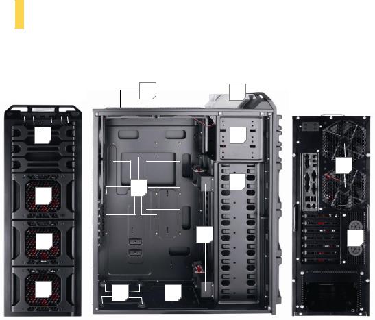
1.1GETTING TO KNOW YOUR CASE
6 |
|
|
|
5 |
|
|
|||
|
|
|
|
|
12 |
|
|
1 |
|
|
|
7 |
|
|
10 |
2 |
|
|
|
|
8 |
|
|
|
8 |
|
3 |
9 |
|
|
||
|
|
|
|
8 |
11 |
4 |
|
|
|
Drive bays |
Hardware mounts |
|
1 |
5.25” drive bays |
10 Motherboard standoffs (pre-installed) |
2 |
3.5” drive bays |
11 Power supply mounts |
3 |
Fleet-Swap SATA bays |
12 Front I/O ports |
4 |
2.5” internal SSD bays |
|
5 |
2.5” external hot-swap |
|
Cooling
6140 mm top TwoCool™ fans
7120 mm rear TwoCool™ fans
8Fleet-Release access door modules w/front variable-speed 120 mm red LED fans
9Water cooling grommets
5

1.2CASE SPECIFICATIONS
CASE TYPE |
Full Tower |
|
|
COLOR |
Matte black |
|
|
DIMENSIONS |
- 23.5” (H) x 8.5” (W) x 19.9” (D) |
|
- 596 mm (H) x 213 mm (W) x 505 mm (D) |
WEIGHT |
26.3 lbs / 11.3 kg |
|
|
COOLING |
2 x top 140 mm TwoCool™ fans |
|
2 x rear 120 mm TwoCool™ red LED fans |
|
3 x front 120 mm red LED fans with speed control knobs |
|
1 x side 120 mm fan to cool graphics cards (optional) |
|
Water cooling capable |
DRIVE BAYS |
9 x internal 3.5” (4 x external 3.5” Fleet-Swap™ drives, position changeable) |
|
|
|
3 x external 5.25” |
|
1 x external top 2.5” hot-swap SATA drive bay |
|
1 x internal bottom-mounted 2.5” SSD drive |
|
|
EXPANSION SLOTS |
7 |
|
|
MOTHERBOARD SIZE |
Mini-ITX, microATX, Standard ATX |
|
|
FRONT I/O PANEL |
1 x USB 3.0 |
|
2 x USB 2.0 |
|
AC’97 / HD Audio In and Out |
6

1.3
 BEFORE YOU BEGIN
In order to ensure that your building experience with the Dark Fleet DF-85 will be a positive one, please take note of the following:
While working inside your Dark Fleet DF-85, keep your case on a flat, stable surface. Make sure your build environment is clean, well-lit, and free of dust.
Antec cases feature rounded edges that minimize the occurrence of hand injuries. Nonetheless, exercise caution and control when handling case interiors. We strongly recommend taking the appropriate time and care when working inside the case. Avoid hurried or careless motions. Please use reasonable precaution.
Handle components and cards with care. Do not touch the components or contacts on a card. Hold a card by its edges. Hold a component such as a processor by its edges, never by its pins.
To avoid electrostatic discharge, ground yourself periodically by touching an unpainted metal surface (such as a connector or screw on the back of this computer) or by using a wrist grounding strap.
Before you connect a cable, ensure that both connectors are correctly aligned and oriented. Bent pins can be difficult to fix and may require replacement of the entire connector.
This manual is not designed to cover CPU, RAM, or expansion card installation. Please consult your motherboard manual for specific mounting instructions and troubleshooting. Before proceeding, check the manual for your CPU cooler to find out if there are steps you must take before installing the motherboard.
Do not sit on your case. Although it is constructed of heavy-duty steel and internally reinforced, it is not designed to support the weight of an adult, and may buckle.
Remember to use the right tools for each task. Do not use improvized screwdrivers like coins, nails or knife blades as they may result in damage to screw threads or even injury. Do not use your fingernails to separate edges or lift the sides of the case, as paint chipping or injury may occur.
7

1.4LOCATING AND POSITIONING YOUR COMPUTER
Your DF-85 has backwardsand top-facing exhaust fans, as well as front-mounted intake fans and one sidemounted front air intake. For optimum performance, we recommend leaving the front air intakes unobstructed.
When open, the DF-85’s Fleet-Release™ doors take up an additional 15.5 cm of space in the front. Since loading and unloading the DF-85’s internal Fleet-Swap™ SATA bays through the doors will require opening and closing them, you may wish to leave space in front of the computer open for this purpose.
The DF-85 comes with a top 2.5” Hot Swap drive bay. While it’s in a handy location, we do not recommend that users put any liquid-containing items (drinks, ice cream, coffee, perfume, etc.) on the drive bay. It was not designed for storage purposes.
8

SECTION 2 
 HARDWARE
INSTALLATION
9
2.1 |
|
SETTING UP |
|
|
|
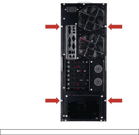
Put the case upright on a flat, stable surface so that the rear panel (power supply and expansion slots) is facing you. To remove the left and right side panels, remove these thumbscrews:
Note: Place the panel thumbscrews aside carefully and remember where they are.
10

Now rest your case with the left side up. Here’s what we’ll be working with first:
E
D |
B |
C
A
A – Power supply mounts
B – 5.25” drive bay area
C – 3.5” drive bay area with Fleet-Swap SATA bays
D – Front panel wiring
E – I/O panel
Note: Do not use your fingernails to pry or lift the panels. Damage to the panels or injury to your fingernails may result.
Note: This manual is not designed to cover CPU, RAM, or expansion card installation. Please consult your motherboard manual for specific mounting instructions and troubleshooting.
11
 Loading...