

Page 1

SERIES
681XXB
SYNTHESIZED SWEEP GENERATOR
OPERATION MANUAL
Serial Number 512001 and above
490 JARVIS DRIVE
MORGAN HILL, CA 95037-2809
P/N: 10370-10298
PRINTED: AUGUST 1995
COPYRIGHT 1995 WILTRON CO.
REVISION: B
Page 2

WARRANTY
The WILTRON product(s) listed on the title page is (are) warranted against defects in materials
and workmanship for one year from the date of shipment, except for YIG-tuned oscillators and all
WILTRON manufactured microwave components, which are warranted for two years.
WILTRON’s obligation covers repairing or replacing products which prove to be defective during
the warranty period. Buyers shall prepay transportation charges for equipment returned to WILTRON for warranty repairs. Obligation is limited to the original purchaser. WILTRON is not liable
for consequential damages.
LIMITATION OF WARRANTY
The foregoing warranty does not apply to WILTRON connectors that have failed due to normal
wear. Also, the warranty does not apply to defects resulting from improper or inadequate maintenance by the Buyer, unauth or ized modification or misuse, or oper ation outside of the environmen tal
specification s of the produc t. No other warran ty i s expressed or implied, an d the remedies pr ovided
herein are the Buyer’s sole and exclusive remedies.
NOTICE
WILTRON Company has prepared this manual for use by WILTRON Company personnel and
customer s as a guide for the proper installation, operation, and maintenan ce of WIL TRON Compan y
equipmen t and comp utor pr ogr ams. Th e draw ings, specifications, an d information co ntain ed he rein
are the property of WILTRON Company, and any unauthorized u se or disclosur e of these draw ing s,
specifications, and information is prohibited; they shall not be reproduced, copied, or used in whole
or in part as the basis for manufacture or sale of the equipment or software programs without the
prior writtten c onsent of WILTRON Company.
Page 3

MANUAL CHANGES
MANUAL :
Title: Series 681XXB Synthesized Sweep Generator Operation Manual
Part Number: 10370-10298
Rev. Ltr/Date: B / Augus t 1995
CHANGE PACKET
Part Number: 10900-00165
INSTRUCTIONS
1. Make the manual changes listed below. The changes are listed in numerical order by page number.
Effectivity is all sweep generator serial numbers.
2. The replacement pages provided are for technical changes to the manual. The black bar or bars in the
replacement page margins shows the area in which the changes were made.
CHANGE 1, November 1995
Safety Symbols
1.
Add enclosed pages Safety-1 and Safety-2 after the Declaration of Conformity page,
Changed: November 1995.
2.
Page 1-4
Replace with enclosed pages 1-3 and 1-4, Changed: November 1995.
3.
Pages 2-3 thru 2-6
Replace with enclosed pages 2-3 thru 2-6, Changed: November 1995.
4.
Page 3-13
Replace with enclosed pages 3-13 and 3-14, Changed: November 1995.
5.
Pages 3-3 4 th ru3-3 6
Replace with enclosed pages 3-33 thru 3-36, Changed: November 1995.
6.
Page 3-41
Repalce with enclosed pages 3-41 and 3-42, Changed: November 1995.
7.
Page 3-71
Replace with enclosed pages 3-71 and 3-72, Changed: November 1995.
8.
Page 4-17
Replace with enclosed page 4-17/4-18, Changed: November 1995.
9.
Pages 6-3 thru 6-7
Replace with enclosed pages 6-3 thru 6-8, Changed: November 1995.
10.
Pages 6-13 thru 6-15
Replace with enclosed pages 6-13 thru 6-15/6-16, Changed: November 1995.
681XXB OM C-1
Page 4

11. Page A-2
Replace with enclosed pages A-1 and A-2, Changed: November 1995.
12.
Pages B-2 thru B-5
Replace with enclosed pages B-1 thru B-6, Changed: November 1995.
PCOs: 22121, 22151, and 22191
C-2 681XXB OM
Page 5

Declaration of Conformity
Application of Council Directive: EMC- 89/336/EEC
Manufacturer: Wiltron Company
490 Jarvis Drive
Morgan Hill, CA 95037
USA
Products: Synthesized CW / Sweep / Signal Generators
Models: 680XXB, 681XXB, 682XXB, 683XXB
Standards: EN 55011: 1991, Group 1, Class A
EN 50082-1: 1992
IEC 801-2, 1991, Level 3
IEC 801-3, 1984, Level 2
IEC 801-4, 1988, Level 2
Signature Date
John Pink
Managing Direct or
Wiltron Measurements LTD.
Wiltron House
Rutherford Close
Stevenage
Herts, SG1 2EF
UNITED KINGDOM
Page 6
Safety Symbols
To prevent the risk of person al inju ry or loss related to equipmen t malfun ctio n, WILTRON Compan y uses
the following symbols to indicate safety -related information. For your own safety, please read the information caref ully BEFORE operating the equipment.
WARNING WARNING indicates a hazard . It calls attention to a procedure that
could result in personal injury or loss of life if not performed properly.
Do not proceed beyon d a WARNING no tice until the in dic ated con ditions are fully under stoo d and met.
CAUTION CAUTION indica tes a hazard. It calls attention to a procedu re which,
if not performed proper ly, could result in damage to or destruction of a
component of the instru men t. Do not procee d beyo nd a CAUTION
note until the indicated condition s are fu lly und er stood and met.
The instrumen t is marked with this symbol to indicate that it is necessary for the user to refer to the instru ction s in the operation manual.
Indicates ground.
Indicates heavy weight equipment.
681XXB OM Safety-1
Page 7
For Safety
WARNING
When supply ing power to this equipment, always use a
three-wir e power cable conn ec te d to a three-w ir e pow er line
outlet. If power is supplied without grounding the equipment in this manner, there is a risk of receiving a severe or
fatal electric shock.
WARNING
Before changing the fuse, always remove the powe r cor d
from the power outle t. There is the risk of receiv in g a fatal
electric sho ck if the fuse is replac ed with the power cord connected.
Always use a new fuse of the type and rating specified by
the fuse markings on the rear pan el of the instr ume nt.
WARNING
There are no operator servic eable c ompon ents inside. Refer
servicing of the instrume nt to qualified serv ice technic ian s.
To prevent the risk of electric al shoc k or damage to precision
components, do not remove the equipment covers.
WARNING
Use two or more people to lift and move this equipment, or
use an equipment cart. There is a risk of back injury, if this
equipment is lifted by one person.
Safety-2 681XXB OM
Page 8

TABLE OF CONTENTS
Chapter 1 — General Informati on
Chapter 1 provides general information about the WILTRON Series 681XXB Synthesized Sweep
Generator. It includes a general description of the sweep generator and information on its identification number, related manuals, options, and performance specifications. A listing of recommended
test equipment is also provided. Chapter contents are detailed immediately following the tab.
Chapter 2 — Installation
Chapter 2 provides installation instructions for the Series 681XXB Synthesized Sweep Generator.
It includes information on initial inspection, preparation for use, storage, and reshipment, and
GPIB setup and interconnections. Chapter contents are detailed immediately following the tab.
Chapter 3 — Local (Fron t Panel) Operation
Chapter 3 provides information and instructions for operating the Series 681XXB Synthesized
Sweep Generator using the front panel controls. It includes illustrations of the front panel, data display area, and data entry area; an annotated diagram of the menu display format; and instructions
for performing sweep generator operations. Chapter contents are detailed immediately following
the tab.
Chapter 4 — Local Operation—Me nu Maps
Chapter 4 provides menu maps that support the local (front panel) operating instructions found in
Chapter 3. It includes menu maps for all of the frequency, power level, and modulation modes of operation plus system configuration. Chapter contents are detailed immediately following the tab.
Chapter 5 — Operati on Veri fication
Chapter 5 provides three operation verification tests that can be used to verify Series 681XXB Synthesized Sweep Generator operation. Setup instructions and step-by-step procedures are included
for each test. Test results can be compared with the specified limits shown on the test record forms
that are provided for each 681XXB model configuration. Chapter contents are detailed immediately
following the tab.
Chapter 6 — Operator Ma intenance
Chapter 6 provides the information necessary for operator maintenance of the sweep generator.
Operator maintenance is limited to basic troubleshooting and repairs that can be made without removing the instrument covers. Chapter contents are detailed immediately following the tab.
Chapter 7 — Use With Other Instrumen ts
Chapter 7 provides information and instructions for using the Series 681XXB Synthesized Sweep
Generator with other WILTRON instruments. Chapter contents are detailed immediately following
the tab.
681XXB OM i
Page 9

Table of Contents (Continued)
Appendix A — Rear Panel Connectors
Appendix A provides descriptions of the rear panel connectors on a typical Series 681XXB Synthesized Sweep Generator. It includes pinout diagrams and descriptions for the AUX I/O and IEEE488 GPIB connectors.
Appendix B — Performanc e Specifications
Appendix B lists the performance specifications for the Series 681XXB Synthesized Sweep
Generator.
Supplements
This tab provides a repository for application notes and other material used to supplement manual
chapters.
Index
Provides a subject index.
ii 681XXB OM
Page 10

Chapter 1
General Information
Table of Contents
1-1 SCOPE OF MANUAL . . . . . . . . . . . . . . . . 1-3
1-2 INTRODUCTION . . . . . . . . . . . . . . . . . . 1-3
1-3 DESCRIPTION . . . . . . . . . . . . . . . . . . . . 1-3
1-4 IDENTIFICATION NUMBER . . . . . . . . . . . . 1-6
1-5 RELATED MANUALS . . . . . . . . . . . . . . . . 1-6
GPIB Programming Manual 1-6
SCPI Programming Manual 1-6
Mainten ance Manual 1-6
1-6 OPTIONS . . . . . . . . . . . . . . . . . . . . . . . 1-7
1-7 PERFORMANCE SPECIFICATIONS . . . . . . . 1-8
1-8 RECOMMENDED TEST EQUIPMENT . . . . . . 1-8
Page 11
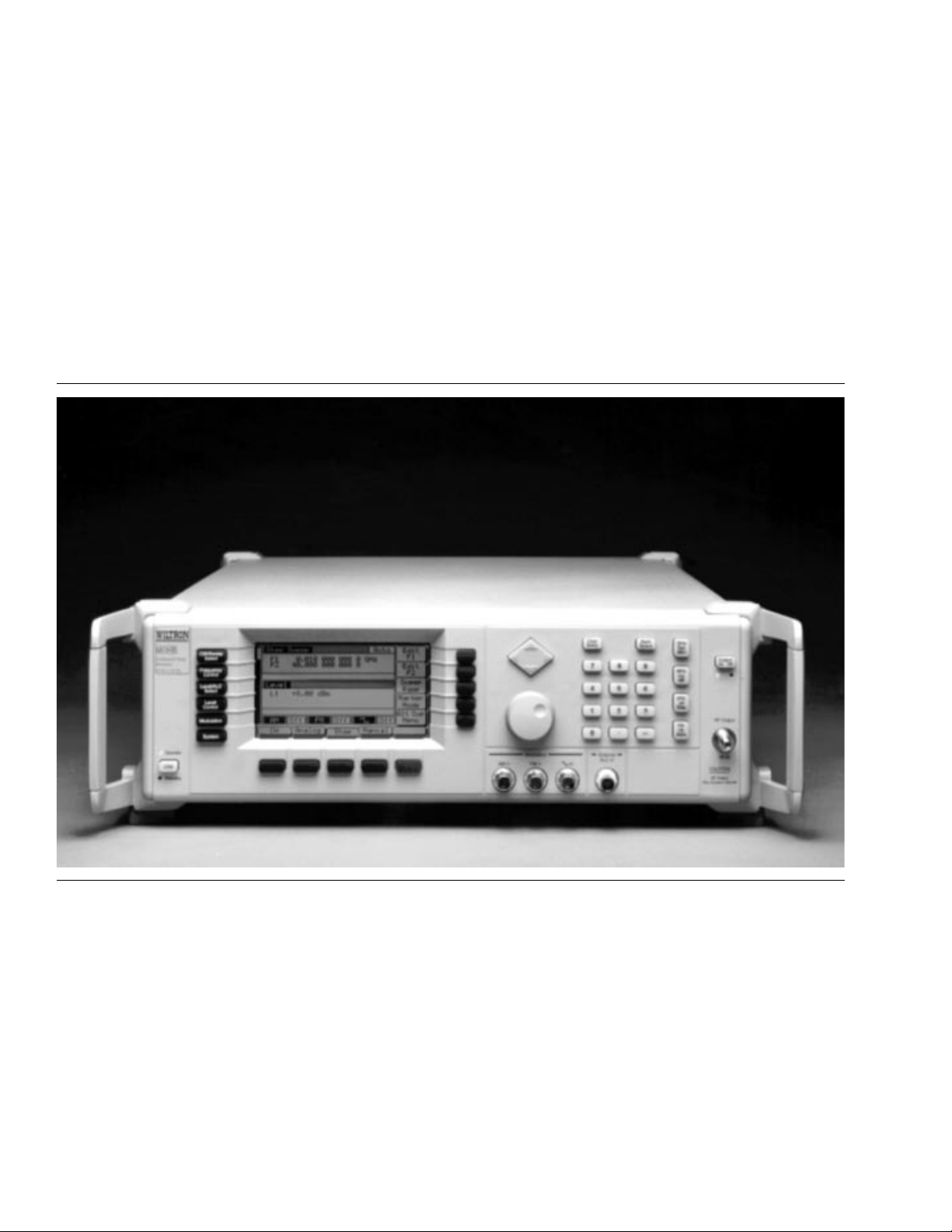
Figure 1-1. Series 681XX B Synthes ize d Sw ee p Gen erator
Page 12

Chapter 1
General Information
1-1
1-2
1-3
SCOPE OF MANUAL
INTRODUCTION
DESCRIPTIO N
This manual prov ides gener al inf orm ation, installation, and operatin g
information for the WILTRON Series 681XXB Syn the sized Sweep Gen-
erator. (Thr oug ho ut this manu al, the terms 681XX B and sweep ge ner-
ator will be used inter ch an geably to refer to the ins trumen t.) M anu a l
organization is shown in the table of contents.
This chapter co ntains general information about the series 681XXB
sweep generator s. It inclu de s a general desc rip tion of the ins trumen t
and information on its identific ation numbe r, related man uals, options,
and perfor manc e specific ation s. A listing of reco mmen ded test equ ipment is also provided.
The Series 681XXB Synthesized Sweep Generators are microprocessorbased, synthesized sign al sou r ce s wi th high resolu tion phase-lock capability. The y gener a te both broad (full r ange) and nar r ow band swe eps
and discrete CW frequ en cies acr os s the frequen cy range of 10 MHz to
65 GHz. All function s of the swe ep gen era tor are fu lly contr ollable locally from the front pan el or remotely (except fo r power on/stand by) via
the IEEE-488 General Pur pose In terf ace Bus (GPIB).
The series presently consists of 15 models coverin g a variety of frequency and pow er rang es. Table 1-1, on page 1-4, lists models, frequency ran ges, and max imum lev eled outpu t.
681XXB OM 1-3
Page 13

GENERAL 681XXB
INFORMATION MODELS
Table 1-1. Series 681X XB M odels (1 of 2)
681XXB
Model
68137B 2.0 – 20.0 GHz +13.0 dBm +11.0 dBm
68145B 0.5 – 20.0 GHz +13.0 dBm +11.0 dBm
68147B 0.01 – 20.0 GHz +13.0 dBm +11.0 dBm
68153B
68155B
68159B
68163B
68165B
68169B
68175B
68177B
68185B
68187B
68195B
Frequenc y
(GHz)
2.0 – 20.0 GHz
20.0 – 26.5 GHz
0.5 – 2.2 G H z
2.2 – 20.0 GHz
20.0 – 26.5 GHz
0.01 – 2.0 GHz
2.0 – 20.0 GHz
20.0 – 26.5 GHz
2.0 – 20.0 GHz
20.0 – 40.0 GHz
0.5 – 2.2 G H z
2.2 – 20.0 GHz
20.0 – 40.0 GHz
0.01 – 2.0 GHz
2.0 – 20.0 GHz
20.0 – 40.0 GHz
0.5 – 2.2 G H z
2.2 – 20.0 GHz
20.0 – 40.0 GHz
40.0 – 50.0 GHz
0.01 – 2.0 GHz
2.0 – 20.0 GHz
20.0 – 40.0 GHz
40.0 – 50.0 GHz
0.5 – 2.2 G H z
2.2 – 20.0 GHz
20.0 – 40.0 GHz
40.0 – 50.0 GHz
50.0 – 60.0 GHz
0.01 – 2.0 GHz
2.0 – 20.0 GHz
20.0 – 40.0 GHz
40.0 – 50.0 GHz
50.0 – 60.0 GHz
0.5 – 2.2 G H z
2.2 – 20.0 GHz
20.0 – 40.0 GHz
40.0 – 50.0 GHz
50.0 — 6 5.0 GHz
Output Power
+9.0 dBm
+6.0 dBm
+13.0 dBm
+9.0 dBm
+6.0 dBm
+13.0 dBm
+9.0 dBm
+6.0 dBm
+9.0 dBm
+6.0 dBm
+13.0 dBm
+9.0 dBm
+6.0 dBm
+13.0 dBm
+9.0 dBm
+6.0 dBm
+11.0 dBm
+10.0 dBm
+2.5 dBm
+2.5 dBm
+12.0 dBm
+10.0 dBm
+2.5 dBm
+2.5 dBm
+11.0 dBm
+10.0 dBm
+2.5 dBm
+2.0 dBm
+2.0 dBm
+12.0 dBm
+10.0 dBm
+2.5 dBm
+2.0 dBm
+2.0 dBm
+11.0 dBm
+10.0 dBm
+2.5 dBm
0.0 dBm
–2.0 dBm
Output Pow er
w/Step Att enuato r
+7.0 dBm
+3.5 dBm
+11.0 dBm
+7.0 dBm
+3.5 dBm
+11.0 dBm
+7.0 dBm
+3.5 dBm
+7.0 dBm
+3.0 dBm
+11.0 dBm
+7.0 dBm
+3.0 dBm
+11.0 dBm
+7.0 dBm
+3.0 dBm
+10.0 dBm
+8.5 dBm
0.0 dBm
–1.0 dBm
+10.0 dBm
+8.5 dBm
0.0 dBm
–1.0 dBm
+10.0 dBm
+8.5 dBm
0.0 dBm
–1.5 dBm
–2.0 dBm
+10.0 dBm
+8.5 dBm
0.0 dBm
–1.5 dBm
–2.0 dBm
Not Available
1-4 681XXB OM
Changed: November 1995
Page 14

GENERAL 681XXB
INFORMATION MODELS
T abl e 1-1. Series 681XXB Models (2 of 2)
681XXB
Model
68197B
68137B 2.0 – 20.0 GHz +17.0 dBm +15.0 dBm
68145B
68147B
68153B
68155B
68159B
68163B
68165B
68169B
68175B 0.5 – 50.0 GHz Standard Standar d
68177B 0.01 – 50.0 GHz Standard Standard
68185B 0.5 – 60.0 GHz Standard Standar d
68187B 0.01 – 60.0 GHz Standard Standard
68195B 0.5 – 65.0 GHz Standard Not Available
68197B 0.01 – 65.0 GHz Standard Not Available
Frequency
(GHz)
0.01 – 2. 0 G Hz
2.0 – 20. 0 G Hz
20.0 – 40.0 GHz
40.0 – 50.0 GHz
50.0 — 65 .0 GHz
With O p ti on 1 5A (H ig h P o we r) Insta lle d
0.5 – 2.2 GHz
2.2 – 20. 0 G Hz
0.01 – 2. 0 G Hz
2.0 – 20. 0 G Hz
2.0 – 20. 0 G Hz
20.0 – 26.5 GHz
0.5 – 2.2 GHz
2.2 – 20. 0 G Hz
20.0 – 26.5 GHz
0.01 – 2. 0 G Hz
2.0 – 20. 0 G Hz
20.0 – 26.5 GHz
2.0 – 20. 0 G Hz
20.0 – 40.0 GHz
0.5 – 2.2 GHz
2.2 – 20. 0 G Hz
20.0 – 40.0 GHz
0.01 – 2. 0 G Hz
2.0 – 20. 0 G Hz
20.0 – 40.0 GHz
Output Pow er
+12.0 dBm
+10.0 dBm
+2.5 dBm
0.0 dBm
–2.0 dBm
+13.0 dBm
+17.0 dBm
+13.0 dBm
+17.0 dBm
+13.0 dBm
+10.0 dBm
+13.0 dBm
+13.0 dBm
+10.0 dBm
+13.0 dBm
+13.0 dBm
+10.0 dBm
+13.0 dBm
+6.0 dBm
+13.0 dBm
+13.0 dBm
+6.0 dBm
+13.0 dBm
+13.0 dBm
+6.0 dBm
Output Power
w/Step Attenuator
Not Available
+11.0 dBm
+15.0 dBm
+11.0 dBm
+15.0 dBm
+11.0 dBm
+7.5 dBm
+11.0 dBm
+11.0 dBm
+7.5 dBm
+11.0 dBm
+11.0 dBm
+7.5 dBm
+11.0 dBm
+3.0 dBm
+11.0 dBm
+11.0 dBm
+3.0 dBm
+11.0 dBm
+11.0 dBm
+3.0 dBm
681XXB OM 1-5
Page 15

GENERAL IDENTIFICATION
INFORMATION NUMBER
1-4
1-5
IDENTIFICATION NUMBER
RELATED MANUALS
All WILTRON instr ume nts are a ssign ed a uniqu e six-dig it ID numbe r,
such as “301001”. The ID number is imprinted on a decal that is affixed to the rear pane l of the unit. Sp ec ial-or der instr ume nt conf igu ra tions also have an additional special serial number tag attached to the
rear panel of the unit.
When ordering parts or corresponding with WI LTRON Customer Serv-
ice, please use the corre ct se rial n umbe r with reference to the specific
instrumen t’s model number (i.e., Model 68147B Synth esized Swee p
Generator, Serial No. 301001).
This is one of a four manual set that consists of an Operation Manual,
a GPIB Programming Manu al, a SCPI Progr amming Man ual, an d a
Mainten ance Manual.
GPIB
Progr am min g
Manual
This manual prov ides info rmation for remote oper ation of the sweep generator with 681XXB Product
Specific comman ds sent from an extern al controller
via the IEEE 488 General Purpose Inter fac e Bus
(GPIB). It contain s a gene ral desc ription of the GPI B
and bus data transfer and contr ol func tion s, a complete listing and description of all 681XX B GPIB
Product Sp ecific comman ds, an d several pr og ramming examples. The WILTRON part number for the
GPIB Programming Manual is 10370-10260.
SCPI
Progr amming
Manual
Mainten an ce
Manual
This manual prov ides info rmation for remote oper ation of the sweep generator with Standar d Commands for Programmable Instrumen t s (SCPI)
commands sent from an ex ternal co ntr oller via the
IEEE 488 General Purpose In te rface Bus (GPI B). I t
contains a general desc rip tion of the GPIB an d bus
data transfer and control functions, a complete li sting and description of each command in the 681XXB
SCPI command set, and examples of command usage. The WILTRON part number for the SCPI Pro-
gramming Manual is 10370-10274.
The Maintenanc e Manual su pplie s service infor mation for all models in the 681XXB series. The service
information inc lu des func tion al cir c uit desc rip tions,
block diagrams, performance verif ication tests, cal ibration procedu re s, troublesh ootin g data, and assembly and component re mov al/r eplac eme nt pr oc edu res.
The WILTRON part number for the Maintenance
Manual is 10370-10262.
1-6 681XXB OM
Page 16

GENERAL
INFORMATION OPTIONS
1-6
OPTIONS
The following options are available.
Option 1, Rack Mounting. Rac k mount kit con tain ing a set of
track slides (90° tilt capability), mounting ear s, and front pane l
handles for mounting the instrument in a standard 19-inch equi pment rack.
Optio n 2A, 110 dB Step Atte nuator . Adds a 10 dB per step
attenuator with a 110 dB range for models having a high- end fre quency of ≤26.5 GHz. Output pow er is selected directly in dBm on
the front panel (or via GPIB). Rated RF output power i s reduc ed.
Option 2 B, 110 dB S tep Att enu a to r . Adds a 10 dB per step
attenuator with a 110 dB range for models having a high- end fre quency of ≤40 GHz. Output power is selected directly in dBm on
the front panel (or via GPIB). Rated RF output power i s reduc ed.
Option 2 C, 90 d B S tep Att enuator. Adds a 10 dB per step
attenuator with a 90 dB range for models hav in g a high -en d fr equency of ≤50 GHz. Output power is selected directly in dBm on
the front panel (or via GPIB). Rated RF output power i s reduc ed.
Optio n 2D, 90 dB Step Atte nuator. Adds a 10 dB per step
attenuator with a 90 dB range for models hav in g a high -en d fr equency of ≤60 GHz. Output power is selected directly in dBm on
the front panel (or via GPIB). Rated RF output power i s reduc ed.
Option 9, Rear Panel RF Output. Moves the RF output connector to the rear panel.
Option 11, 0.1 Hz Frequency Resolut ion. Provides frequency
resolution of 0.1 Hz.
Optio n 1 4, WI LTRON 360 B VNA Co mp a ti bi l it y. Modifies rack
mounting hardware to mate unit in a WILTRON 360B VNA con-
sole.
Option 15A , H igh Powe r Ou tpu t . Ad ds h igh -p ow er RF c omp onents to the instrument providing increased RF output power in
the 2–26.5 GHz frequency ran ge. Option 15A is standard in models having a high-end frequency that is >40 GHz.
Option 16, High-Stability Time Base. Adds an ovenized,
10 MHz crystal oscillator with <5 x 10
Option 17A, No Front Panel. Deletes the front pan el for use in
remote control applic a tions wher e a front pan el di splay or keyboard control are not needed.
Option 19, SCPI Programmability . Adds G PI B comman d mn emonics complying with Stan dard Commands for Programmable
Instruments (SCPI), Version 1993. 0. SCPI programmin g complies
with IEEE 488.2-1987.
–10
/day frequency stability.
681XXB OM 1-7
Page 17

GENERAL RECOMMENDED
INFORMATION TEST EQUIPMENT
1-7
1-8
PERFORMANCE
SPECIFICATIONS
RECOMMENDED TEST
EQUIPMENT
Series 681XXB Synthe size d Sweep Generator performance specific ations are prov ided in Appen dix B.
Table 1-2 lists the recommended test equipment for performing the Series 681XXB Synthe sized Sweep Generator oper ation verific a tion tests
in Chapter 5.
T abl e 1-2. Recommended Te st Equi pmen t
Instrument Critical Specification Recommended Manufacturer/Model
Range:
Frequency
Counter,
with
Cable Kit
and
External Mixer
Power Meter,
with
Power
Sensor
Oscilloscope
0.01 to 65 GHz
Input Z: 50
Resolution:
Other:
Input
Range:
(1µW to 100 mW)
Bandwidth:
Ver tic al Se ns itiv ity:
division
Horiz Sensitivity:
division
Ω
1 Hz
External Time Base
–30 to +20 dBm
DC to 150 MHz
50 ns/
2 mV/
EIP Microwave, Inc. Models 538B,
548B, or 578B,
with
Cable Kit: Option 590
and
External Mixer:
Option 91 (26.5 to 40 GHz)
Option 92 (40 to 60 GHz)
Option 93 (60 to 90 GHz)
Hewlett-Packard Model 437B,
with
Power Sensor:
HP 8487A (0.01 to 50 GHz)
Tektronix, Inc. Model TAS485
Adapter K (male) to 2.4 mm (female)
Adapts the Pow er Sensor,
HP 8487A, to the 681XXB
RF OUTPUT connector
(≤40 GHz models)
Hewlett-Packard
Part Number: HP 11904D
1-8 681XXB OM
Page 18

Chapter 2
Installation
Table of Contents
2-1 INTRODUCTION . . . . . . . . . . . . . . . . . . 2-3
2-2 INITIAL INSPECTION . . . . . . . . . . . . . . . 2-3
2-3 PREPARATION FOR USE . . . . . . . . . . . . . 2-4
Power Requirements . . . . . . . . . . . . . . . . 2-4
Line Voltage Selection . . . . . . . . . . . . . . . 2-4
Power Connection . . . . . . . . . . . . . . . . . . 2-4
Standby Operation . . . . . . . . . . . . . . . . . 2-5
Warmup Time . . . . . . . . . . . . . . . . . . . . 2-6
Operating Environment . . . . . . . . . . . . . . 2-6
2-4 GPIB SETUP AND INTERCONNECTION . . . . . 2-7
Interface Connector . . . . . . . . . . . . . . . . . 2-7
Cable Length Restrictions . . . . . . . . . . . . . 2-7
GPIB Interconnection . . . . . . . . . . . . . . . 2-7
Setting the GPIB Address . . . . . . . . . . . . . 2-7
Selecting the Line Terminator . . . . . . . . . . . 2-9
Selecting the Interface Language . . . . . . . . . 2-9
2-5 PREP ARATION FOR STORAG E/SHIPMENT . . . 2-10
Preparation for Storage . . . . . . . . . . . . . . . 2-10
Preparation for Shipment . . . . . . . . . . . . . 2-10
Page 19

Chapter 2
Installation
2-1
2-2
INTRODUCTION
INITIAL INSPECTION
This chapter prov ides installation instruction s for the Series 681XX B
Synthesized Sweep G en era tor. It includes inf or m ation on initial inspec tion, preparation for use, storage, and reshipment, and General Purpose Interface Bus (GPIB) setup and interconnections.
WARNING
Use two or more people to lift and move this equipment, or
use an equipment cart. There is a risk of back injury, if this
equipment is lifted by one person.
Inspect the shippin g contain er for damage . If the shippin g contain er or
cushioning material is damaged, retain until the contents of the shipment have been checked against the pack ing list and the sweep generator has been checked for mechanical and electrical operation.
If the shipment is incomplete or if the sweep gen er ator is damaged mechanically or electr ic ally, notify your local sales represent ative or WIL-
TRON Customer Service. If either the shippin g contain er is damaged
or the cushionin g material shows sig ns of stress, no tify the car rie r as
well as WILTRON. Keep the shipping materials for the carr ier’s insp ec -
tion.
681XXB OM 2-3
Changed: November 1995
Page 20
PREPARATION
INSTALLATION FOR USE
2-3
PREPARATION FOR USE
Prepara tion for use c onsists of checking that the rear panel line voltage selector swi tch is set for the cor re ct line voltage and c onne ctin g the
sweep generator to the power so urc e. The followin g parag r aph s provide
these procedu r es along with information about pow er requ ir emen ts,
warmup times, and the ope ratin g envir on men t.
Power
Requiremen ts
Before applying power, verify that the unit i s set to match
the available line voltage and tha t the installed fuse is of the
correct type and rating.
Line Voltage
Selection
The sweep generator accepts 90 to 132 Vac and 180
to 264 V ac , 48 to 400 Hz, single-ph ase p ower. Pow er
consumption is 400 VA maximum.
CAUTION
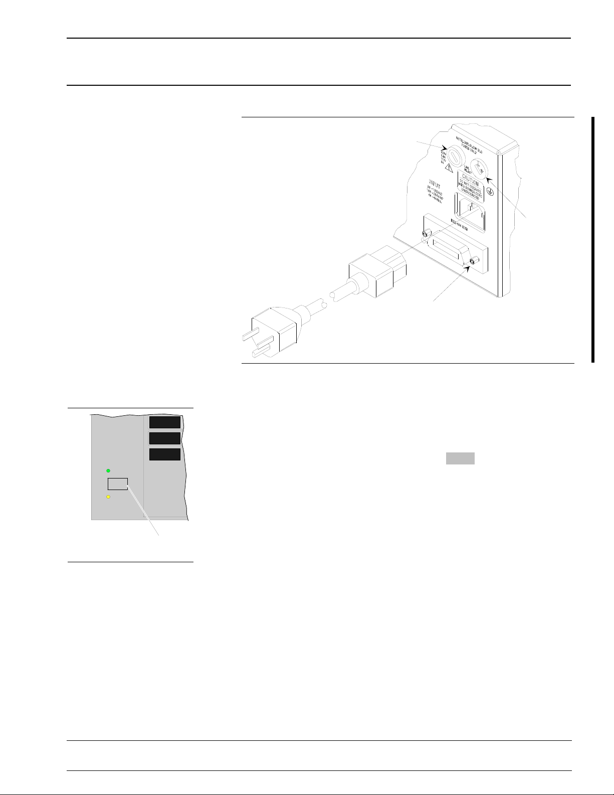
The line voltage selector switc h on the rear pan el
can be set for either 110 Vac or 220 Vac operation
(Figure 2-1). Wh en the switc h is set to 1 10 Vac, the
681XXB accepts 90 to 132 Vac line voltage. When
the switch is set to 220 Vac, the 681XXB accepts 180
to 264 V ac line voltage. If the selector setting is incorrect for the line voltage available, change it to the
correct setting.
Whenever the selector setting is changed, the line
fuse must be changed to the correct value for the
line voltage selected. Lin e fuse values for the line
voltages are printed on the rear pan el ne xt to the
fuse holder.
WARNING
When supply ing power to this equipmen t, always use a
three-wir e pow er cable con ne cted to a three-w ir e power line
outlet. If power is supplied without grounding the equipment
in this manner, there is a risk of receivin g a severe or fa tal
electric shock.
Power
Connection
Connecting the 681XXB to line pow er automatically
places it in operation (front panel OPERATE LED
on). To connect it to the power source, plug the female end of the power cable into the input line voltage receptacle on the re ar pan el (Fig ure 2-1). Then
plug the male end of the power cord into a threewire power line outlet.
2-4 681XXB OM
Changed: November 1995
Page 21
PREPARATION
Figure 2-1. Sweep Generator Re ar Panel showing Power Connecti on
INSTALLATION FOR USE
Line
Fuse
Line Voltage
Selector Switch
GPIB
Connector
OPERATE
LINE
STANDBY
LEVEL
CONTROL
MODULATION
SYSTEM
Line
Key
Standby Operation
Whenever the swee p gener ator is not being used it
should be left connec ted to the power sour c e and
placed in standby. This keeps the internal timebase
frequency refer en c e at operatin g temperatu r e.
On the front panel, press
LINE to switch the
681XXB from OPERATE (green LED on) to
STANDBY (orange LED on).
NOTE
During standby operation, the fan runs
continuously.
681XXB OM 2-5
Changed: November 1995
Page 22

PREPARATION
INSTALLATION FOR USE
W armup
Time
Operating
Environment
Before installing the 680XXB in its operating envir on men t,
ensure that all airflo w passage s at the sides an d rear of the
instrumen t are clear. This is of particular importan c e whenever the unit is being rack-mo unted.
From a cold start (ac power application ), the sweep
generator requ ire s approx imately 120 hours (5 days)
of warm up to achieve 2 x 10
racy and stability.
If the Option 16 time base is installed, the 681XXB
requires approx imately 72 hours (3 days) of w arm
up to achieve 5 x 10
stability.
When placing the 681XXB in ope ration from standby, allow 30 minutes warmup to assure stable operation.
The 681XXB can be oper ated with in the follow in g environmental limits.
Temperature. 0°C to 50°C (-32°F to 122°F).
Humidity. 5 to 95% relative at 40°C.
Altitude. up to 4600 meters (approximately
15,000 feet).
Cooling. Internal cooling is provided by forced
airflow from the fan mounted on the rear panel.
CAUTION
–10
–8
/day frequ en cy ac cu -
/day frequency accuracy and
Keep the cooling fan filter clean so that the ven tilation holes
are not obstru cted . A blocked fan filter can cause th e in stru ment to overheat and shut down.
2-6 681XXB OM
Changed: November 1995
Page 23

GPIB SETUP AND
INSTALLATION INTERCONNECTION
2-4
GPIB SETUP AND
INTERCONNECT ION
The 681XXB provides automated microwave signal generation via the
GPIB. The follow in g par ag rap hs pr ovide inf or m ation abou t inter fac e
connection s, cable requ ire men ts, setting the GPIB oper atin g param eters, and selecting the external interface language.
Interface
Connector
Cable Length
Restrictions
Interfac e betwee n the sweep g en er ator an d other devices on the GPIB is via a 24-wire interf ace cable.
This cable uses connector shells hav in g two conn ector faces. These double- fac ed co nnec tor s allow for
the parallel connection of two or more cables to a single device. Figure 2-1 show s the loca tion of the rear
panel GPIB conn ec tor.
The GPIB can accommod a te up to 15 instruments at
any one time. To ach iev e design per for man c e on the
bus, proper timin g and vo ltage lev el re la tionsh ip s
must be maintained. If either the cable leng th between separate instrume nts or the cumulativ e cable
length between all instruments is too long, the data
and control lines cannot be driven properly and the
system may fail to perform. Cable length restric tion s
are as follows:
No more than 15 ins trumen t s may be in stalled
on the bus.
Total cumulative cable len gth in meters may
not exceed two times the number of bus instruments or 20 meters—whichev er is less.
NOTE
For low EMI applications, the GPIB cable
should be a fully shielded type , with wellgrounded metal-shell connectors
GPIB In terconnection
Setting the
GPIB
Address
The only intercon n ection requ ir ed for GPI B oper ation is between the sweep gen era tor an d the contr oller. This interconnection is via a standard GPIB
cable. The WILTRON Part number for suc h a cable
is 2000-1, -2, or -4 (1, 2, or 4 meters in length).
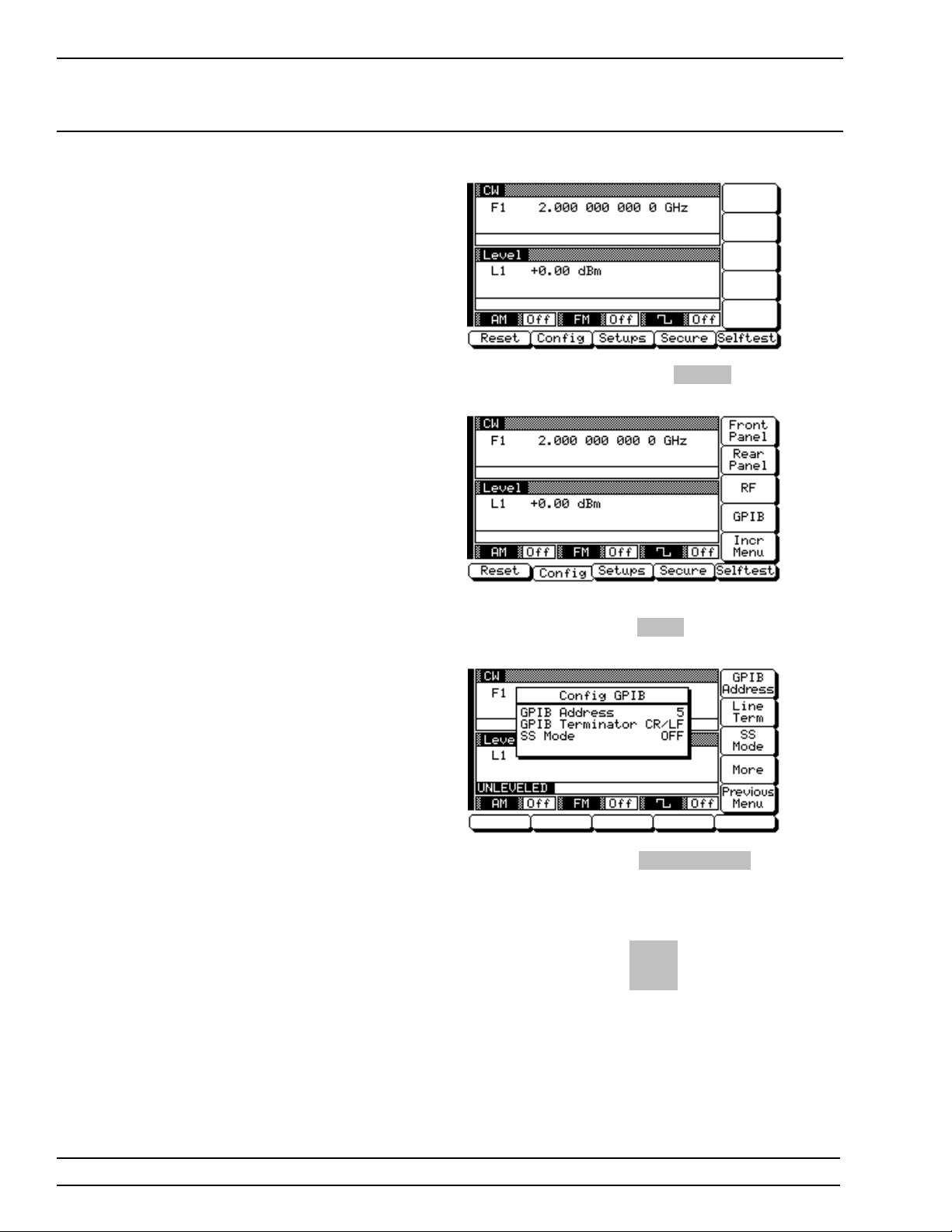
The default GPIB add ress i s 5. If a different GPI B
address is desired, it can be set from the front panel
using the Config ur e GPIB Me nu .
To change the GPIB address, first press the front
panel main menu key labele d
tem Menu (shown on the following page) is displayed.
SYSTE M . The Sys-
681XXB OM 2-7
Page 24
GPIB SETUP AND
INSTALLATION INTERCONNECTION
Now press the menu soft-key Co nf ig . The System
Configuration Menu (below) is displayed.
To go to the Configure GPIB men u from this menu,
press the menu soft-key
Menu (below) is displayed.
Press the menu soft-key
the current GPI B addre ss of the sweep ge ne rator.
Enter a new addr ess u sing th e c ursor control key or
the data entry keypad and the termin ator key
The new GPIB address will now appear on the di splay. The entr y must be betwee n 1 and 30 to be recognized as a valid GPIB address.
GPIB . Th e Confi gu r e GPIB
GPIB Address to change
Hz
ns
ADRS
2-8 681XXB OM
Page 25
GPIB SETUP AND
INSTALLATION INTERCONNECTION
Selecting
the Li n e
Terminator
Selecting the
Interface
Language
Data is delimited on the GPIB by either the carriag e
return (CR) ASCII char ac ter or both the car riag e r eturn and line fe ed (CR/ LF) A SCII c har ac ter s. Wh ic h
character is used depen ds upon the requirements of
the system controller. Most modern controlle rs can
use either CR or CR/LF, while many older controllers require one or the other. Consult the controller’s
manual for its particu lar requir emen t s.
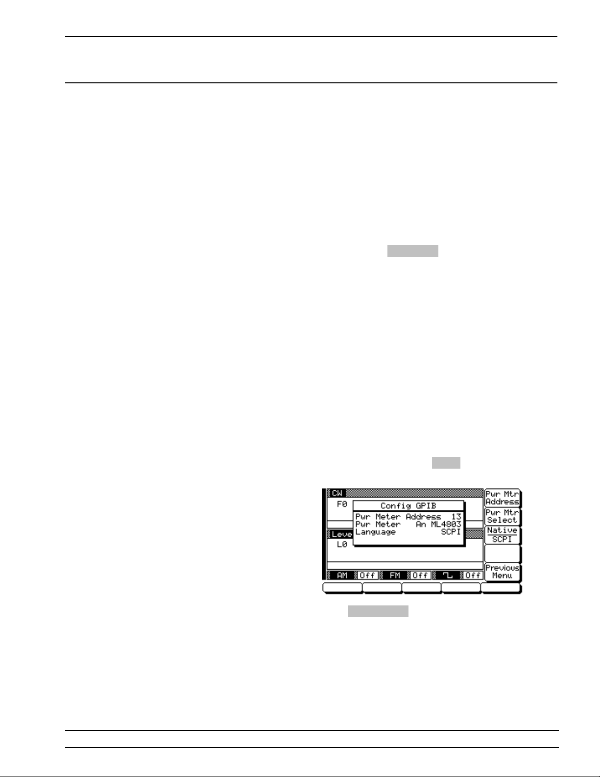
From the Configu re GPIB Men u display, you can select which GPIB termin ator to use by pressin g the
menu soft-key
gles the GPIB terminator between CR and CR/LF.
The current selec tion appears on the display.
Series 681XXB Synthesized Swe ep Ge ne rator s can
be remotely operated via the GPIB usin g one of two
external interf ace lang uages— N ative or SCPI (Option 19). The Native interfac e lang uag e uses a set of
681XXB GPIB Produc t Specific comman ds to contro l
the instrument; the SCPI inter fac e lan guag e uses a
set of the Standard Commands for Programmable Instruments comman ds to control the u nit.
The Configure G PIB Menu has an additional men u
display. For ins tru men ts with Option 19, selection of
which exter n al inter fac e lang u ag e is to be used is
made from this additional menu. From the Con fig ure GPIB Menu display, you can access the additional menu by pressing
figure GPIB Men u (below) is displayed.
Line Term . This menu soft-key tog-
More . The additional Con-
Press
Native SCPI to select the external in terf ace
language to be used. This menu soft-key togg les the
language selec tion betw een Native and SCPI. The
current selection appears on the display.
681XXB OM 2-9
Page 26

PREPARATION FOR
INSTALLATION STORAGE/SHIPMENT
2-5
PREPARATION FOR
STORAGE/SHIPMENT
The following paragraphs give instructions for preparing the 681XXB
for storage or shipment.
Preparation
for Storage
Preparation
for Shipment
Preparing the sweep generator for storage consists
of cleaning the unit, packing the insid e with moisture-absorbing desiccant crystals, and storing the
unit in a temperature environ men t that is maintained between –40°C and +75°C (–40°F to +176°F ).
To provide maximum protection against damage in
transit, the sweep generator shou ld be re pac kag ed
in the original shipping container. If this container is
no longer available and the unit is being retu rned to
WILTRON for repair , adv ise WIL T RO N Customer
Service; they will send a new shippin g con tainer free
of charge. In the event neither of these two options
is possible, instruction s for pac kaging and shipment
are given below.
Use a Suitable Con tain er.
Obtain a corrugated cardboar d carton with a 275pound test strength. This carton should have inside
dimensions of no less than six inche s large r than the
unit dimensions to allow for cushioning.
Protect the Instrument.
Surround the un i t wi th poly ethylene sheeting to pro tect the finish.
Cushion the Inst rume nt .
Cushion the instrument on all sides by tightly packing dunnag e or ure than e foam betwe en the carton
and the unit. Provide at least three inches of dunnage on all sides.
Seal the Cont aine r.
Seal the carton by using eithe r shippin g tape or an
industrial stapler.
Address the Container.
If the instrument i s being retu rned to WILTRO N for
service, mark the address o f the appropr iate WIL-
TRON service center (Table 2-1) and your return address on the carton in one or more prominent
locations.
2-10 681XXB OM
Page 27

UNITED STATES
WILTRON COMPANY
490 Jarvis Drive
Morgan Hill, CA 95037-2809
Telephone: (408) 778-2000
Telex: 285227 WILTRON MH
FAX: (408) 778-0239
ANRITSU WILTRON SALES
COMPANY
685 Jarvis Drive
Morgan Hill, CA 95037-2809
Telephone: (408) 776-8300
FAX: (408) 776-1744
ANRITSU WILTRON SALES
COMPANY
10 Kingsbridge Road
Fairfield, NJ 07004
Telephone: (201) 227-8999
FAX: (201) 575-0092
AUSTRALIA
WILTRON PTY. LTD.
Level 2, 410 Church Street
North Parramatta
NSW 2151 Australia
Telephone: 026-30-81-66
Fax: 026-83-68-84
BRAZIL
ANRITSU WILTRON ELECTRONICA LTDA.
Praia de Botafogo, 440-SL 2401-Botafogo
2225-Rio de Janeiro-RJ-Brasil
Telephone: 021-28-69-141
Fax: 021-53-71-456
CANADA
ANRITSU WILTRON INSTRUMENTS LTD.
215 Stafford Road, Unit 102
Nepean, Ontario K2H 9C1
Telephone: (613) 828-4090
FAX: (613) 828-5400
CHINA
WILTRON BEIJING SERVICE
CENTER
416W Beijing Fortune Building
5 Dong San Huan Bei Lu
Chao Yang Qu, Beijing 100004,
China
Telephone: 86-1-50-17-559
FAX: 86-1-50-17-558
FRANCE
ANRITSU WILTRON S.A
9 Avenue du Quebec
Zone de Courtaboeuf
91951 Les Ulis Cedex
Telephone: 016-44-66-546
FAX: 016-44-61-065
GERMANY
ANRITSU WILTRON GmbH
Rudolf Diesel Strabe 17
8031 Gilching
Telephone: 08-10-58-055
FAX: 08-10-51-700
INDIA
MEERA AGENCIES (P) LTD.
A-23 Hauz Khas
New Delhi 110 016
Telephone: 011-685-3959
FAX: 011-686-6720
ISRAEL
TECH-CENT, LTD
Haarad St. No. 7, Ramat Haahayal
Tel-Aviv 69701
Telephone: (03) 64-78-563
FAX: (03) 64-78-334
ITALY
ANRITSU WILTRON Sp.A
Roma Office
Via E. Vittorini, 129
00144 Roma EUR
Telephone: (06) 50-22-666
FAX: (06) 50-22-4252
JAPAN
ANRITSU CORPORATION
1800 Onna Atsugi-shi
Kanagawa-Prf. 243 Japan
Telephone: 0462-23-1111
FAX: 0462-25-8379
KOREA
WILTRON CORPORATION
#2103 Korea World Trade Center
159-1 Samsung-Dong
Kangnam-ku, Seoul
Telephone: (02) 551-2250
FAX: (02) 551-4941
SINGAPORE
ANRITSU WILTRON (SINGAPORE) PTE LTD
3 Shenton Way #24-03
Shenton House
Singapore 0106
Telephone: 011-65-2265206
FAX: 011-65-2265207
SWEDEN
ANRITSU WILTRON AB
Box 247
S-127 25 Skarholmen
Telephone: (08) 74-05-840
FAX: (08) 71-09-960
TAIWAN
WILTRON CO., LTD.
8F, No. 96, Section 3
Chien Kuo N. Road
T aipei, Taiwan, R.O.C.
Telephone: (02) 515-6050
FAX: (02) 509-5519
UNITED KINGDOM
ANRITSU WILTRON LTD.
200 Capability Green
Luton, Bedfordshire
LU1 3LU, England
Telephone: 05-82-41-88-53
FAX: 05-82-31-303
Table 2-1. WILTRON Service Centers
WILTRON
INSTALLATION SERVICE CENTERS
681XXB OM 2-11/2-12
Page 28

Chapter 3
Local (Front Panel) Operation
Table of Contents
3-1 INTRODUCTION . . . . . . . . . . . . . . . . . . 3-5
3-2 FRONT PANEL LAYOUT . . . . . . . . . . . . . . 3-6
Line Key . . . . . . . . . . . . . . . . . . . . . . . 3-6
Data
Display Area . . . . . . . . . . . . . . . . . . . . . 3-6
Data
Entry Area . . . . . . . . . . . . . . . . . . . . . . 3-7
RF Output
Control Key . . . . . . . . . . . . . . . . . . . . . 3-7
Connectors . . . . . . . . . . . . . . . . . . . . . . 3-7
3-3 DATA DISPLAY AREA . . . . . . . . . . . . . . . . 3-8
Menu
Display
Format . . . . . . . . . . . . . . . . . . . . . . . . 3-9
Menu Keys . . . . . . . . . . . . . . . . . . . . . 3-10
3-4 DATA ENTRY AREA . . . . . . . . . . . . . . . . . 3-12
3-5 INSTRUMENT START-UP . . . . . . . . . . . . . 3-12
Powering Up the 681XXB . . . . . . . . . . . . . 3-12
Start-Up
Display . . . . . . . . . . . . . . . . . . . . . . . . 3-12
Standby
Operation . . . . . . . . . . . . . . . . . . . . . . 3-12
Self-Testing the 681XXB . . . . . . . . . . . . . . 3-13
Resetting to Default Parameters . . . . . . . . . . 3-13
Page 29

3-6 ENTERING DATA . . . . . . . . . . . . . . . . . . 3-16
Opening the Parameter . . . . . . . . . . . . . . . 3-16
Editing the Current Value . . . . . . . . . . . . . 3-17
Entering a New Value . . . . . . . . . . . . . . . 3-18
3-7 CW FREQUENCY OPERATION . . . . . . . . . . 3-19
Selecting CW Mode . . . . . . . . . . . . . . . . . 3-19
Selecting
a CW
Frequency . . . . . . . . . . . . . . . . . . . . . . 3-19
Selecting a Power Level . . . . . . . . . . . . . . 3-21
CW Ramp . . . . . . . . . . . . . . . . . . . . . . 3-22
3-8 SWEEP FREQUENCY OPERATION . . . . . . . . 3-23
Selecting Analog Sweep Mode . . . . . . . . . . . 3-23
Setting the Analog Sweep Time . . . . . . . . . . 3-24
Selecting a Sweep
Trigger . . . . . . . . . . . . . . . . . . . . . . . . 3-25
Selecting Step Sweep Mode . . . . . . . . . . . . . 3-26
Setting Step Size and Dwell Time . . . . . . . . . 3-27
Selecting Manual Sweep Mode . . . . . . . . . . . 3-28
Selecting a Sweep Range . . . . . . . . . . . . . . 3-29
Selecting a Power Level . . . . . . . . . . . . . . 3-31
Frequency Markers . . . . . . . . . . . . . . . . . 3-32
Selecting
Alternate Sweep Mode . . . . . . . . . . . . . . . 3-34
3-9 FIXED POWER LEVEL OPERATION . . . . . . . 3-37
Selecting Fixed Power Level Mode . . . . . . . . . 3-37
Selecting a Power Level . . . . . . . . . . . . . . 3-37
Level Offset . . . . . . . . . . . . . . . . . . . . . 3-40
3-10 POWER LEVEL SWEEP OPERATION . . . . . . . 3 -41
Selecting CW Power Sweep Mode . . . . . . . . . 3-41
Setting CW Power Sweep Step Size
and Dwell Time . . . . . . . . . . . . . . . . . . 3-42
Selecting a CW Power Sweep
Trigger . . . . . . . . . . . . . . . . . . . . . . . . 3-43
Selecting a Power Level Sweep Range . . . . . . . 3-44
Selecting a Sweep Frequency / Step Power Mode . 3-46
Setting Power Level Step Size . . . . . . . . . . . 3-47
Page 30

3-11 LEVELING OPERATIONS . . . . . . . . . . . . . 3-48
Selecting a Leveling Mode . . . . . . . . . . . . . 3-48
Attenuator Decoupling . . . . . . . . . . . . . . . 3-52
ALC Power Slope . . . . . . . . . . . . . . . . . . 3-53
User Cal (User Level Flatness
Correction) . . . . . . . . . . . . . . . . . . . . . . 3-55
3-12 SIGNAL MODULATION . . . . . . . . . . . . . . 3-61
Amplitude Modulation Operating Modes . . . . . 3-61
Providing Amplitude Modulation . . . . . . . . . 3-61
Frequency Modulation Operating Modes . . . . . 3-62
Providing Frequency Modulation . . . . . . . . . 3-63
Square Wave Modulation Operating Modes . . . . 3 -65
Providing Square Wave Modulation . . . . . . . . 3-65
3-13 SYSTEM CONFIGURATION . . . . . . . . . . . . 3-68
Configuring the Front Panel . . . . . . . . . . . . 3-69
Configuring the Rear Panel . . . . . . . . . . . . 3-70
Configuring the RF . . . . . . . . . . . . . . . . . 3-71
Configuring the GPIB . . . . . . . . . . . . . . . . 3-72
Setting
Increment Sizes . . . . . . . . . . . . . . . . . . . 3-74
3-14 SAVING/ RECALLING INSTRUMENT SETUPS . 3-75
Saving
Setups . . . . . . . . . . . . . . . . . . . . . . . . 3-75
Recalling Setups . . . . . . . . . . . . . . . . . . 3-75
Erasing Stored
Setups . . . . . . . . . . . . . . . . . . . . . . . . 3-76
3-15 SECURE OPERATION . . . . . . . . . . . . . . . 3-77
Page 31

Chapter 3
Local (Front Panel) Operation
3-1
INTRODUCTION
This chapter pr ov ides in formation and instructio ns on op er a ting the
Series 681XXB Synthe size d Sweep Generator using the front panel
controls. It contains the follo win g:
Illustrations and diagr ams of the fro nt pan el, data di splay ar ea,
and data entry area that identify and describe all fron t panel controls, inputs, and outputs.
An annotated diag r am of th e menu display format show ing
where the current fre que ncy, power , and modulation info rmation
is displayed.
Instructions for performing sweep generator operations; namely,
frequency and frequency sweep, power level and power sweep,
signal modulation, savin g and recallin g instrumen t setups, and
system configuration.
681XXB OM 3-5
Page 32
LOCAL (FRONT FRONT PANEL
PANEL) OPERATION LAYOUT
3-2
SYNTHESIZED
SWEEP
GENERATOR
OPERATE
LINE
STANDBY
FRONT PANEL LAYOUT
Data Display Data Entry
CW/SWEEP
SELECT
FREQUENCY
CONTROL
LEVEL/ALC
SELECT
LEVEL
CONTROL
MODULATION
SYSTEM
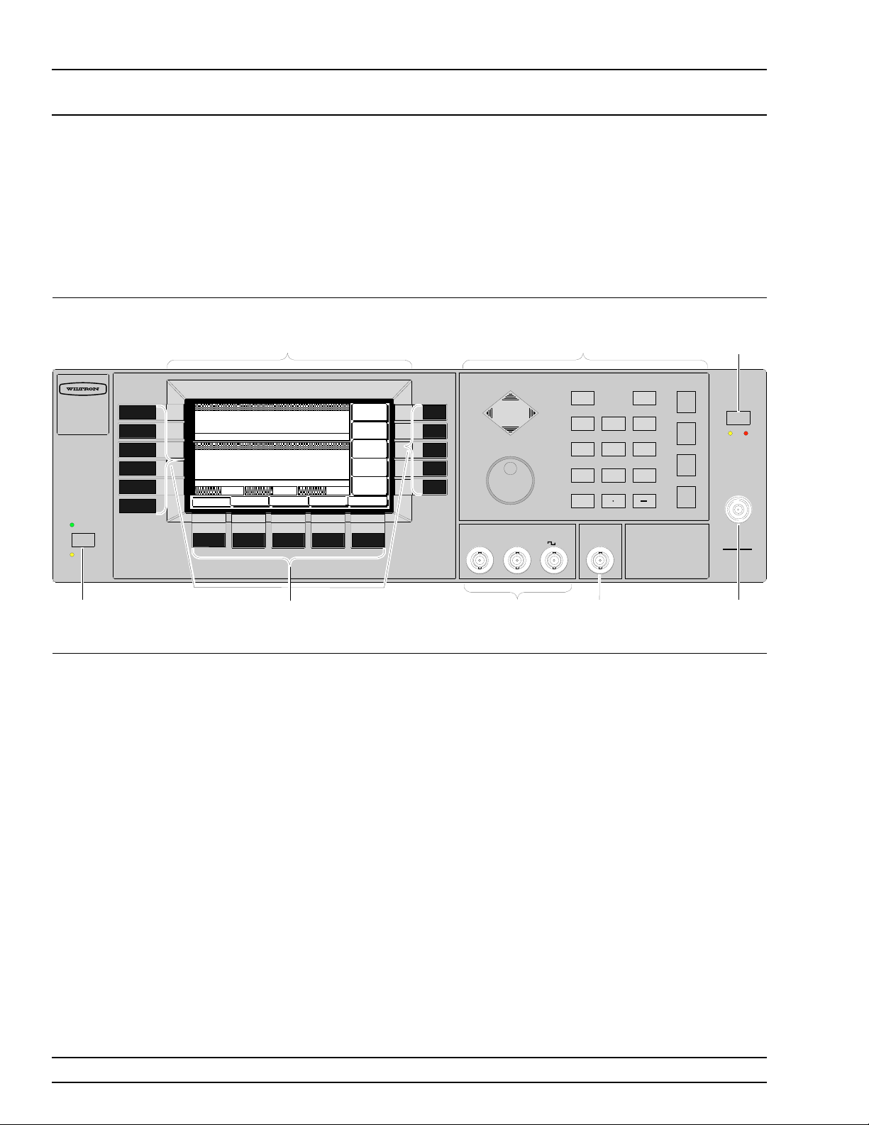
The 681XXB front panel is divided into two main areas—the data display area and the data entry area. The follow ing par agr aph s p rovid e a
brief description of the front panel contr ols, inpu ts, outpu ts, and data
display and da ta entry are a s as shown in Figure 3-1. De tailed descr iptions of the data display and data entry areas are containe d in paragraphs 3-3 and 3-4.
RF Output
Control
Key
CLEAR
ENTRY
7
0
MODULATION
AM IN
FM IN
EXTERNAL
ALC IN
IN
BACK
SPACE
231
GHz
Sec
dBm
98
MHz
ms
dB
654
kHz
µ
s
STEPS
Hz
ns
ADRS
OUTPUT
OFF
ON
RF OUTPUT
Ω
50
CAUTION
RF OUTPUT
MAY EXCEED 100mW
Line
Key
Menu
Keys
Figure 3-1. Front Panel, 681X X B Synthes ize d Sw ee p Gen erator
Line Key The line key provides for turning the sweep gener-
ator on and off. STANDBY (off) is indic ated by an orange LED; OPERATE (on) by a green LED.
Data
Display Area
The data display area consists of the data display
and the surrounding menu keys.
Data Display
The data display provides information about the current status of the 681XXB in a menu display format. This information inclu des the ope ratin g mode
of the instrument, the valu e of the active fr equ en cy
and power lev el parame ters, and the modulation
status.
Menu Keys
Menu keys provide for selecting the ope ratin g mode,
parameters, and configuration of the sweep generator.
Modulation
Connectors
External
ALC
Connector
RF Output
Connector
3-6 681XXB OM
Page 33

LOCAL (FRONT FRONT PANEL
PANEL) OPERATION LAYOUT
Data
Entry Are a
RF Output
Control Key
Connectors The front panel has both input and output connec-
The data entry area consists of data entry keys and
controls th a t provide for (1) changing valu es for
each 681XXB par ameter, and (2) terminatin g the
value entry and assigning the appropriate units
(GHz, MHz, dBm, etc. ).
The RF output control ke y prov ides for tur ning the
RF output power on and off . OUT PUT OF F is indicated by a red LED; OUTPUT ON by a yellow LED.
tors.
Modulation Connectors
The modulation connectors provide for applying external AM, FM, or Squar e Wav e modu lation to the
RF output signal.
Externa l ALC Co nnecto r
The extern al ALC c onn ec tor p ro vid es for leveling
the RF output signal externally using either a
detector or a power meter.
RF Output Co n nect or
The RF outpu t con nector provides RF outpu t from a
50Ω source.
NOTE
To prevent power losses du e to an impedance mismatch, the mating connector and
cable should also be rated at 50 Ω.
681XXB OM 3-7
Page 34
LOCAL (FRONT DATA DISPLAY
PANEL) OPERATION AREA
3-3
Main Menu
Keys
DAT A DISPLAY AREA
Main Menu
Key Cursor
CW/SWEEP
SELECT
FREQUENCY
CONTROL
Frequency
Mode
Title Bar
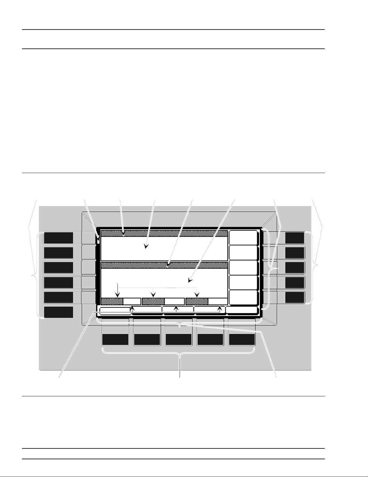
The data display area consists of the data display and the surroundin g
menu keys. The data display is a dot matrix liquid crystal display
(LCD) that provides 16 lines of 40 characters each. Information is presented on the LCD in the form of menu displays. The menu key s
either selec t the main me nu to be display ed, select a sub-menu of the
current men u display, or control a function on the current menu display.
Figure 3-2 shows the for m at of the menu display an d id entif ies the di splay elements. It also shows the placemen t o f the menu keys in re lation to the display. The paragr aph s that follow provide descr iption s of
the menu display element s and the menu ke ys.
Frequency
Parameters
Area
Level Mode
Title Bar
Level
Parameters
Area
Menu
Labels
Side Keys
Menu
Soft-Keys
LEVEL/ALC
SELECT
LEVEL
CONTROL
MODULATION
SYSTEM
Modulation
Status Areas
Figure 3-2. Front Panel Data Displ ay Are a
Modulation
Title Bars
Menu
Soft-Keys
Menu Labels
Bottom Keys
3-8 681XXB OM
Page 35

LOCAL (FRONT DATA DISPLAY
PANEL) OPERATION AREA
Menu
Display
Format
The menu display is divided into specific areas that
show the frequ en cy, power level, and modulation information for the cur ren t sweep g ener a tor setup.
Menu labels for the curren t menu ’s soft-keys appear
along the bottom and right side of the display.
Title B ar s
A shade d title bar identifies eac h parameter area.
Mode information is displayed in reverse video on
the title bars.
Frequen cy Mo de T i tl e Bar —The current frequency mode ( C W, Analog Sweep, Step Sw eep ,
or Manual Sweep) appe ars on the left side of
the bar . In an analog or step sweep mode, the
type of sweep trigger (Auto, Exter n , or Single)
appears on the right side.
Level Mode Title Ba r —The current power
level mode (Level or Level Sweep) appears on
the left side of the bar. In a level sweep mode,
the type of sweep trigger (Au to , Extern al, or
Single) appears on the right side of the bar.
Modulation Title Bars—Each type of signal
modulation (AM, FM, Square Wave) has a
separate title bar on the display.
Parameter A reas
The parameter are as show the frequency, power
level, and modulation infor m ation for the cur ren t
681XXB setup.
Frequen cy Para meters Area —The curren t
CW frequency in GHz, or the start and stop frequencies of the curr en t frequ en c y sweep r ang e
in GHz are displayed in this area.
Power Level Pa rameter s Area —The current power leve l in dBm, or the start an d stop
levels of the curre nt pow er level sw eep rang e
in dBm are displayed in this area.
Modulation Status Areas—These areas display ON or OFF to indicate the status of signal
modulation for the current setup.
Menu Labels
Each of the menu soft-keys, located below an d to
the right of the display, has a corresponding me nu
label area on the display. These labels identify the
function of the soft-keys for the current menu display. In most cases, when a menu soft-key is
pressed, its menu label changes appear anc e to visually show the On/Off cond i tion.
681XXB OM 3-9
Page 36
LOCAL (FRONT DATA DISPLAY
PANEL) OPERATION AREA
Window Display
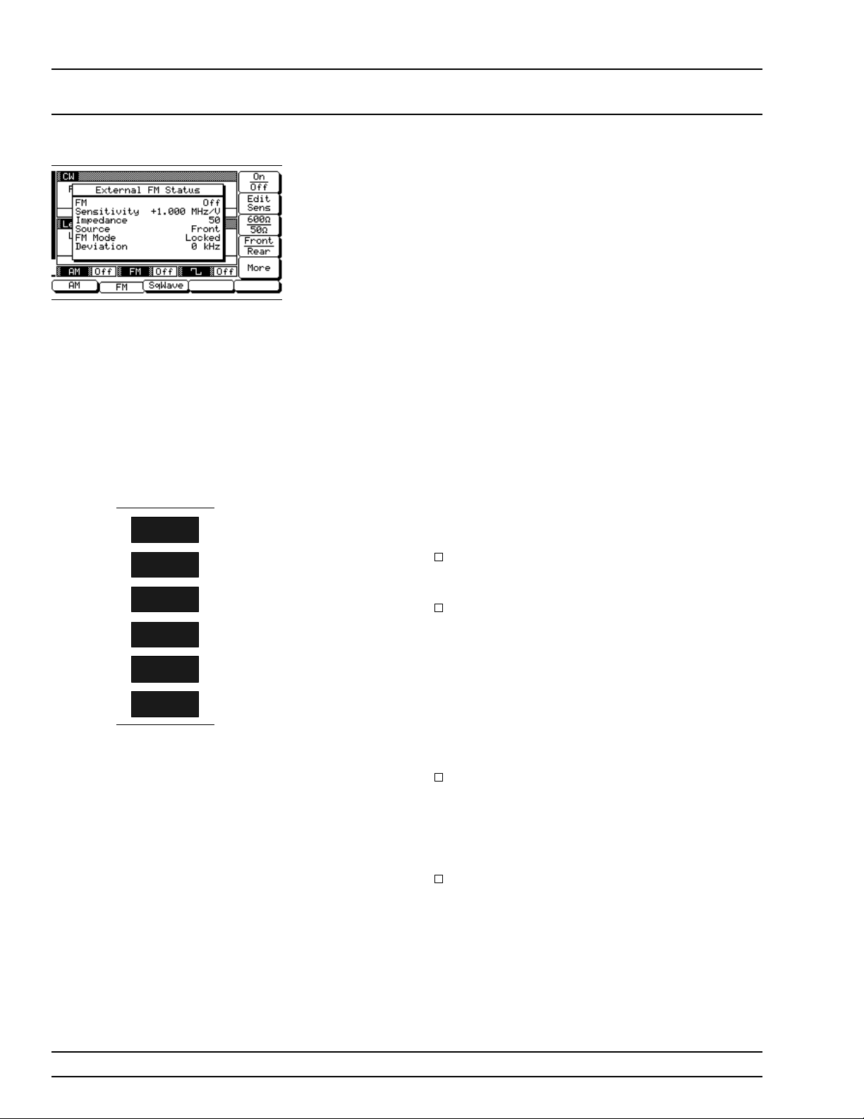
A window display that overlays a portion of the current menu display is used to (1) show the parameter
being edited; (2) di splay selection lists of preset frequencies, pow er lev els, mark er s, etc. ; (3) show the
modul ation and sys tem con fig u ration choic es and
current se lec tio ns; or (4) show self-test err or messages. A typical window di splay is show n on the left.
Menu Keys As show n in Figure 3-2, there are two types of menu
keys that surrou nd the data display— main men u
keys and menu soft-keys. The main menu keys are
positioned to the left of the data display. The menu
soft-keys are located a t the bottom and to the right
of the data display.
Main Menu Keys
Each of the main menu keys, show n on the left, selects a main (top-level) men u display. These menus
let you select the operatin g mode, operatin g para me-
CW/SWEEP
SELECT
FREQUENCY
CONTROL
LEVEL/ALC
SELECT
LEVEL
CONTROL
MODULATION
SYSTEM
ters, and con fig uration of the in str umen t. A brief
functional description of each main menu follows.
CW/SWEEP SELECT—This menu lets you
select between C W, Analog, Step, and M anual
Sweep frequency modes.
FREQUENCY CONTROL—In CW frequency
mode, this menu lets you select the CW frequency paramete r (F0-F9 or M0-M 9) to use. In
the Analog, Step, or Manu al Sw eep f re que ncy
mode, this menu lets you select the sweep
range parameter s (Full, F1-F2, F3-F 4, F5-dF,
or F6-dF) to use. In Analog or Step Sweep f re quency mode, the menu also lets you select up
to 20 independent, pre-se ttable frequ en cy
markers.
LEVEL/ALC SELECT—This menu lets you
select power leve l and ALC modes (Lev el,
Level Sweep, Level Of fset, ALC on or off , inter nal or external ALC, ALC/ attenuator decoupling, ALC slope, and user lev el flatn ess correc tion).
LEVEL CONTROL—In Level mode, this
menu lets you select the level par ameter (L0L9) to use for a CW frequency or a frequency
sweep. In the Level Sweep mode, this menu
lets you select the power sweep range parameters to use.
3-10 681XXB OM
Page 37
LOCAL (FRONT DATA DISPLAY
PANEL) OPERATION AREA
MODULATION—This menu provides you
with access to sub-menus that let you select
the type of signal modulation (AM , FM, or
Square W ave) and control the option settings
for each type.
SYSTEM—Th is me nu pr ov ides y ou with access to sub-menus that let you (1) reset the instrument to factory-selec ted def ault valu es; (2)
configu r e the fr on t panel, rear pan el, RF, and
GPIB; (3) set incremen tal sizes for editing frequency, power level, and time parameters; (4)
save or recall instrument setups; (5) disable
front panel data display; and (6) perfor m instrument self-test.
Main Menu Key Cursor
With the exception of the
main menu key is pressed, the main menu that is
displayed contain s a cursor position ed adjac ent to
the pressed key (Fig ure 3-2). The cursor i s displayed
on all sub-menus of the curre nt men u until a differ ent main menu key is pressed .
SYSTE M key, when any
CW/SWEEP
SELECT
FREQUENCY
CONTROL
LEVEL/ALC
SELECT
CONTROL
MODULATION
SYSTEM
When the
SYSTEM key is pressed, the System
menu is displayed. The System menu and its submenus do not contain a main menu key cursor.
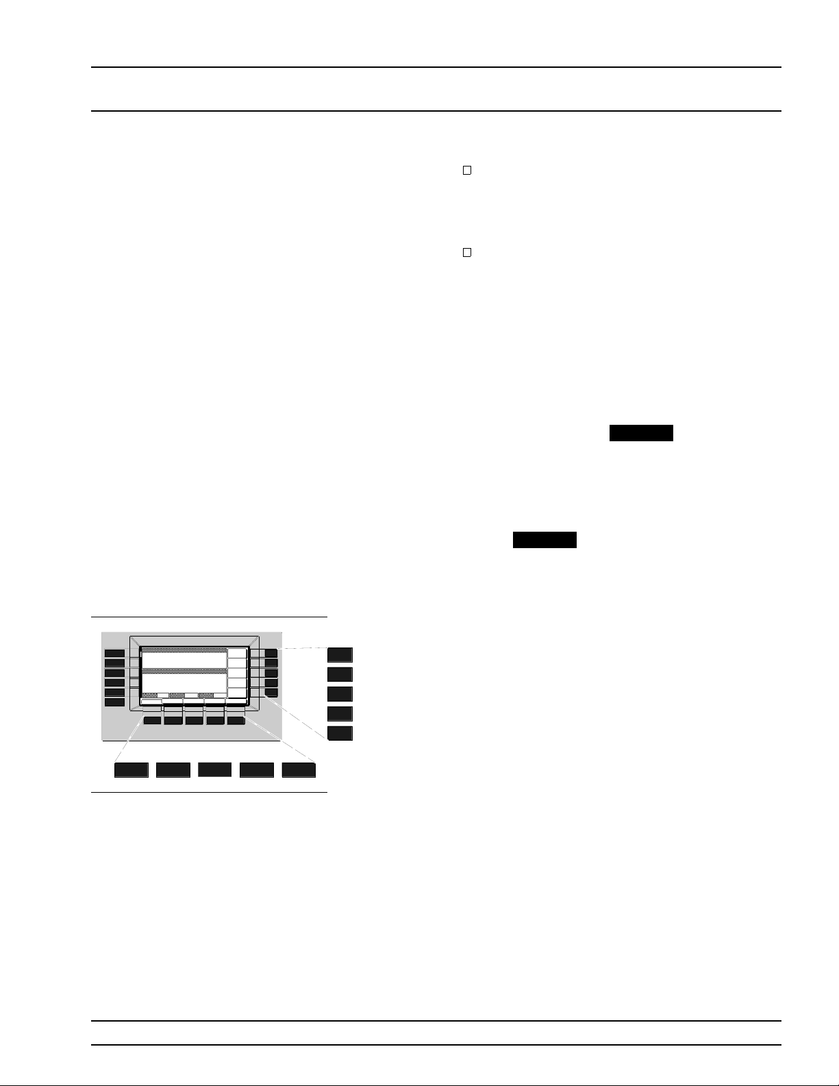
Menu Soft-Keys
As shown on the left, five menu soft-keys are located below the data display and five menu softkeys are located to the right of the data display. In
LEVEL
general, the menu soft-keys located below the data
display select a sub-me nu of the curren t main (toplevel) menu display; the menu soft-keys located to
the right of the data display either contr ol a func tion on the current men u display or select an additional sub-menu. Menu labels that identify the
current fu nc tion of each soft-key are shown on the
menu display adjacent to the soft-keys.
681XXB OM 3-11
Page 38
LOCAL (FRONT DATA ENTRY
PANEL) OPERATION AREA
3-4
DATA ENT RY AREA
Cursor
Control
Key
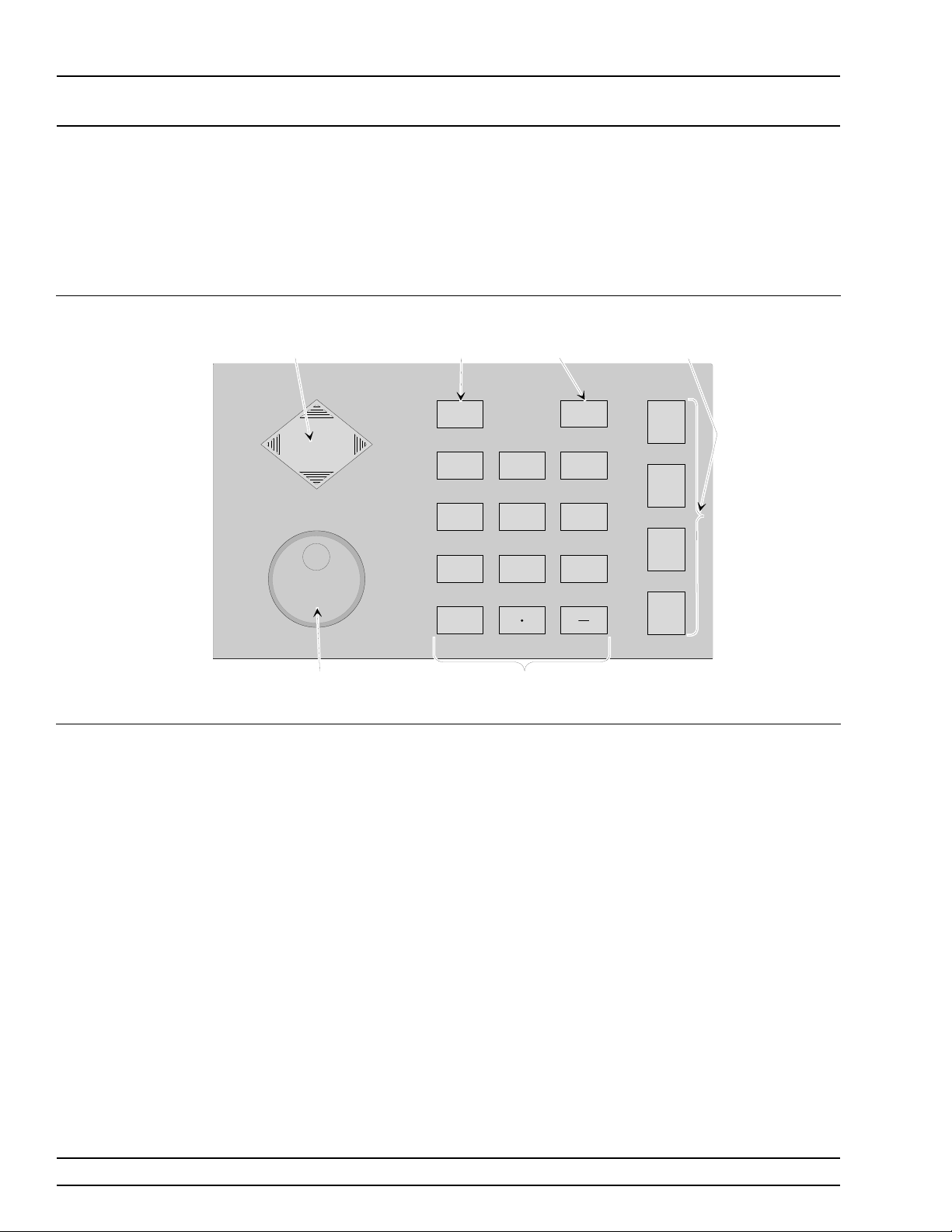
The value of a selected 681XX B par ameter can be chan g ed usin g the
rotary data knob and/or keys of the data entry ar ea. Eac h element of
the data entry area is identified in Figur e 3-3 and desc ribe d in the following paragraphs.
87
5
2
Back
Space
Key
BACK
SPACE
9
6
3
Terminator
Keys
GHz
Sec
dBm
MHz
ms
dB
kHz
µ
s
STEPS
Hz
ns
ADRS
Clear
Entry
Key
CLEAR
ENTRY
4
1
0
Rotary
Data
Knob
Figure 3-3. Front Panel Data Entry Are a
Keypad
Cursor Control Key
In general, this diamon d-sh aped ke y con trols the
movemen t of the cursor on the di splay. When a parameter is opened for edi ting, a cur sor appe ars under the open parame ter. Each time the < or > pad is
pressed , the cursor moves left or right by one digi t.
The ∧ or ∨ pad can then be used to in c r ease or decrease the value of the parame ter. The unit size of
the increase or decrease that oc cur s each time the ∧
or ∨ pad is pressed is determined by the cursor position.
In addition, when edi ting fre que ncy, power level,
and time parameters, the incremental size can be
set to a specific value using a system config uration
sub-menu. Onc e set and activated, each time the ∧
or ∨ pad is pressed, the parameter’s value increases
or decreases by the set amount.
3-12 681XXB OM
Page 39

LOCAL (FRONT DATA ENTRY
PANEL) OPERATION AREA
Rota r y Data Kno b
The rotary data knob can be used to change the
value of a parameter that is open for editing . The
cursor is moved under the open par ameter using
the < and > pads of the cursor control key. Then, by
slowly turning the knob clockwise or counter-clockwise the value of the parameter is incre ased or decreased by the unit size. The unit size is determine d
by the cursor placement. Turning the knob rapidly
changes the valu e of the parameter in larger steps.
When editing frequ enc y, power level, and time parameters, the incremental size can be set to a specific value usin g a system configu ration sub-men u .
Once set and activated, eac h time the knob is
turned clock wise or coun ter - clo ckw i se, the parameter’s value increases or decreases by the set
amount.
KEYPAD
The numeric keypad provides for entering frequency, power level, time, and number-of - steps parameters and GPIB address values. The “–” key
functions as a “change sign” key du ring any key pad
entry.
CLEAR ENT R Y Key
When a parameter is open for editing, the CLEAR
ENTRY key is used to clear the par ameter entry.
BACK SPAC E Key
The BACK SPACE key is used to correct keypad
data entry erro rs by deleting the last number, “–”,
or decimal point enter ed.
Terminator Keys
The termina tor keys are used to termin ate key pad
data entries and chan ge the paramete r value s in
memory. If the enter ed value is outside the allowable range of the open parameter, an error message
will be displaye d alo ng with an audible “beep”. The
terminator keys are as follows:
GHz / Sec / dBm
MHz / ms / d B
kHz / µs / STEPS
Hz / ns / ADRS
681XXB OM 3-13
Page 40
LOCAL (FRONT INSTRUMENT
PANEL) OPERATION START-UP
3-5
INSTRUMENT START-UP
Now that you have familiarized yourse lf with the layout of the sweep
generator’s front panel c on trols and data display, you are ready to begin operating the instrumen t. Begin by powering it up.
Powerin g Up
the 681XXB
Connect th e 681XXB to an ac pow er sou rc e by following the procedure in the Installation chapter.
This automatically places the instr umen t in oper ation (front panel OPERATE LED on).
Start-Up
Display
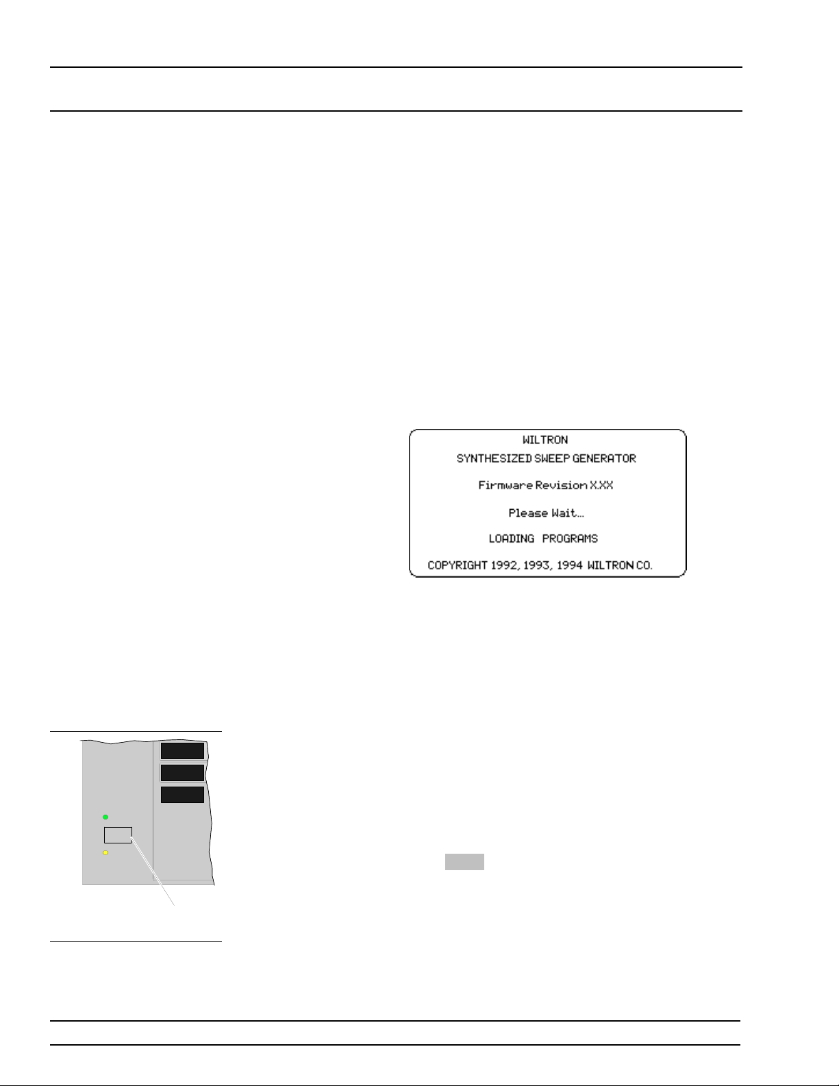
During pow er up, the start-u p di splay (belo w) appears on the data display. It provide s you with the
revision level of the installed firmware and informs
you that instrument is loading programs. The startup display remains displaye d until the sweep gener ator has loaded all programs.
OPERATE
LINE
STANDBY
LEVEL
CONTROL
MODULATION
SYSTEM
Line
Key
Standby
Operation
Upon completion of pow er up , the 681XXB retur n s
to the exact config u ration it was in when last
turned off.
Wheneve r the sweep gen er a tor is not being used, it
should be left connected to the power source and
placed in standby. Standby operation provides
power to keep the inter nal time base at operatin g
temperature. This assures specified frequency accuracy and stability when the 681XXB is place in operation.
NOTE
During standby operation, the fan runs
continuously.
Press
LINE to swi tch the 681XX B fr om OPERA TE
(green LED on) to STANDBY (orange LED on).
NOTE
When switching to operate from standby,
allow at least a 30-minute warmup before
beginning sweep generator operations.
3-12 681XXB OM
Page 41
LOCAL (FRONT INSTRUMENT
PANEL) OPERATION START-UP
Self-Testing
the 681XXB
During self-test with RF OUT PUT set to ON, the output
power level is set to 0 dBm. Always disc on n ect sensitive
equipment from the unit before performing self-test.
The 681XXB firmware includes internal diagnostics
that self-test the instrumen t. The se self-test diag nostics perform a brief go/no -go test of most of the
PCBs and other internal assemblies. If the sweep
generator fails self-test, an error message is displayed on the data display. Error messages and descriptions ar e listed in the Operator Maintenan ce
chapter of this manual.
CAUTION
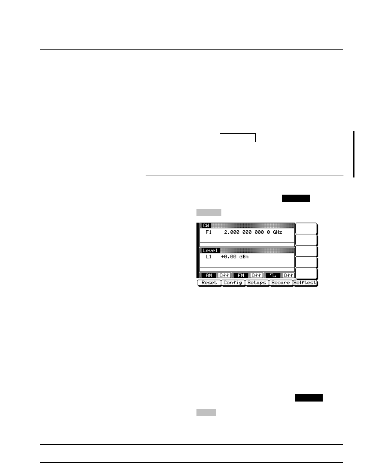
You can perform a self-test of the sweep generator
at any time during normal operation. To perfo rm a
self-test from any menu, press
when the System Menu (below ) is displayed, press
Selftest .
SYSTEM . Then,
Resetting to
Default Pa rameters
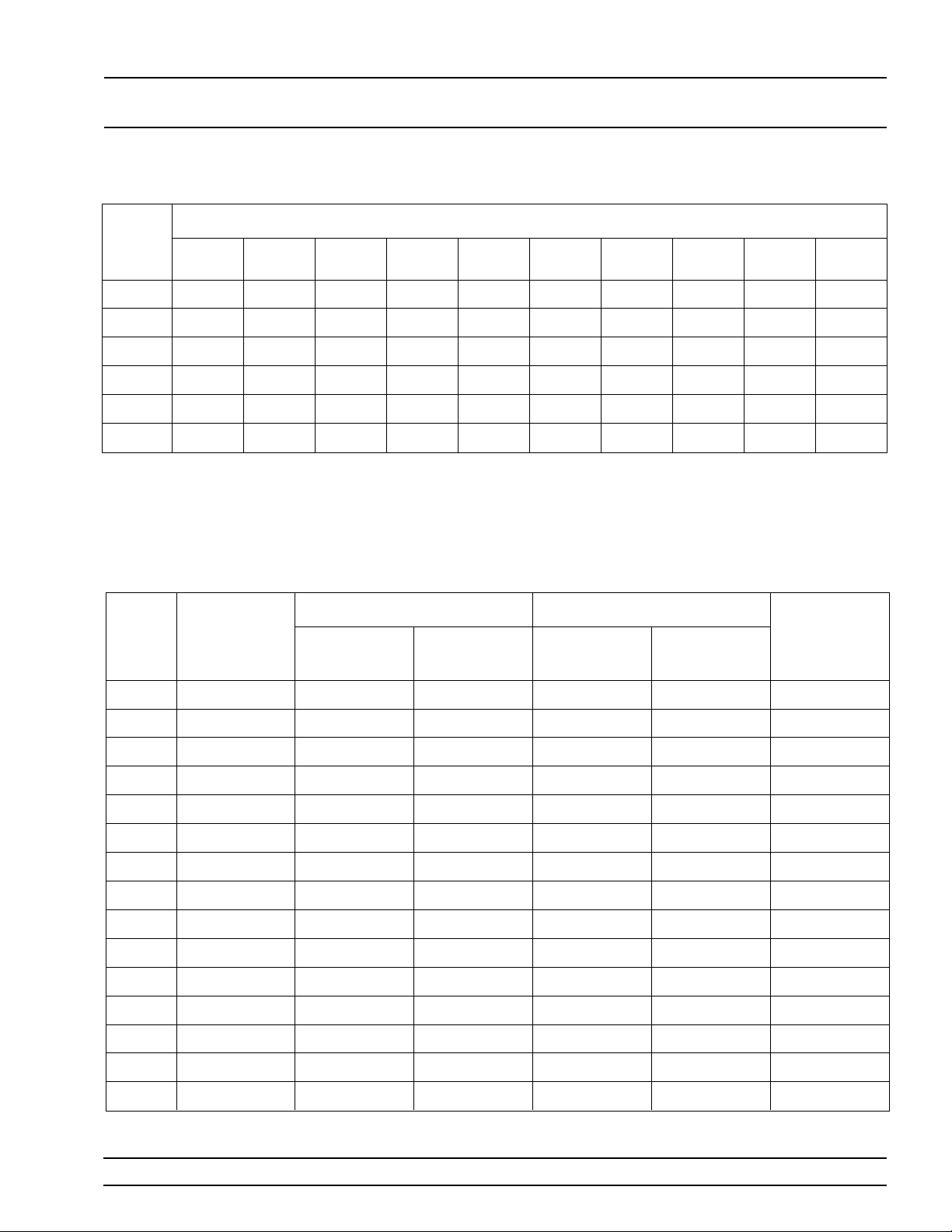
You can reset the 681XXB to the factor y -selec ted default parameter values at any time during normal
operation . The defau lt parameter s are shown in Table 3-1 on the followin g page.
NOTE
Resetting the instru men t clears the setup
presently in place. If these par ameter values are needed for future testing, save
them as a stored setup before resetting
the sweep generator. (For information on
saving/recalling instrument setups, refer
to paragraph 3-14.)
To reset the sweep generator, press
When the System Menu (above) is displayed, press
Reset .
SYSTEM .
681XXB OM 3-13
Changed: November 1995
Page 42

LOCAL (FRONT RESET (DEFAULT)
PANEL) OPERATION PARAMETERS
Table 3-1. Reset (Default) Param e nter s (1 of 2)
681XXB
MODEL
NUMBER
68137B 3.5 2.0 20.0 2.0 5.0 8.0 1 1.0 14.0 17.0 20.0 3.5 2.0 20.0 2.0 5.0 8.0 11.0 14.0 17.0 20.0 1.0
68145B 3.5 2.2 20.0 2.0 5.0 8.0 1 1.0 14.0 17.0 20.0 3.5 2.0 20.0 2.0 5.0 8.0 11.0 14.0 17.0 20.0 1.0
68147B 3.5 2.0 20.0 2.0 5.0 8.0 1 1.0 14.0 17.0 20.0 3.5 2.0 20.0 2.0 5.0 8.0 11.0 14.0 17.0 20.0 1.0
68153B 3.5 2.0 26.5 2.0 5.0 8.0 1 1.0 14.0 17.0 20.0 3.5 2.0 26.5 2.0 5.0 8.0 11.0 14.0 17.0 20.0 1.0
68155B 3.5 2.2 26.5 2.0 5.0 8.0 1 1.0 14.0 17.0 20.0 3.5 2.0 26.5 2.0 5.0 8.0 11.0 14.0 17.0 20.0 1.0
68159B 3.5 2.0 26.5 2.0 5.0 8.0 1 1.0 14.0 17.0 20.0 3.5 2.0 26.5 2.0 5.0 8.0 11.0 14.0 17.0 20.0 1.0
68163B 3.5 2.0 40.0 2.0 5.0 8.0 1 1.0 14.0 17.0 20.0 3.5 2.0 40.0 2.0 5.0 8.0 11.0 14.0 17.0 20.0 1.0
68165B 3.5 2.2 40.0 2.0 5.0 8.0 1 1.0 14.0 17.0 20.0 3.5 2.0 40.0 2.0 5.0 8.0 11.0 14.0 17.0 20.0 1.0
68169B 3.5 2.0 40.0 2.0 5.0 8.0 1 1.0 14.0 17.0 20.0 3.5 2.0 40.0 2.0 5.0 8.0 11.0 14.0 17.0 20.0 1.0
68175B 3.5 2.2 50.0 2.0 5.0 8.0 1 1.0 14.0 17.0 20.0 3.5 2.0 50.0 2.0 5.0 8.0 11.0 14.0 17.0 20.0 1.0
68177B 3.5 2.0 50.0 2.0 5.0 8.0 1 1.0 14.0 17.0 20.0 3.5 2.0 50.0 2.0 5.0 8.0 11.0 14.0 17.0 20.0 1.0
68185B 3.5 2.2 60.0 2.0 5.0 8.0 1 1.0 14.0 17.0 20.0 3.5 2.0 60.0 2.0 5.0 8.0 11.0 14.0 17.0 20.0 1.0
68187B 3.5 2.0 60.0 2.0 5.0 8.0 1 1.0 14.0 17.0 20.0 3.5 2.0 60.0 2.0 5.0 8.0 11.0 14.0 17.0 20.0 1.0
68195B 3.5 2.2 65.0 2.0 5.0 8.0 1 1.0 14.0 17.0 20.0 3.5 2.0 65.0 2.0 5.0 8.0 11.0 14.0 17.0 20.0 1.0
F0 F1 F2 F3 F4 F5 F6 F7 F8 F9 M0 M1 M2 M3 M4 M5 M6 M7 M8 M9
FREQUENCY PARAMETERS (GHz)
∆F
68197B 3.5 2.0 65.0 2.0 5.0 8.0 1 1.0 14.0 17.0 20.0 3.5 2.0 65.0 2.0 5.0 8.0 11.0 14.0 17.0 20.0 1.0
681XXB
MODEL
NUMBER
68137B +1.0 0. 0 –1.0 –2.0 –3.0 –4.0 –5.0 –6.0 –7.0 –8.0
68145B +1.0 0. 0 –1.0 –2.0 –3.0 –4.0 –5.0 –6.0 –7.0 –8.0
68147B +1.0 0. 0 –1.0 –2.0 –3.0 –4.0 –5.0 –6.0 –7.0 –8.0
68153B +1.0 0. 0 –1.0 –2.0 –3.0 –4.0 –5.0 –6.0 –7.0 –8.0
68155B +1.0 0. 0 –1.0 –2.0 –3.0 –4.0 –5.0 –6.0 –7.0 –8.0
68159B +1.0 0. 0 –1.0 –2.0 –3.0 –4.0 –5.0 –6.0 –7.0 –8.0
68163B +1.0 0. 0 –1.0 –2.0 –3.0 –4.0 –5.0 –6.0 –7.0 –8.0
68165B +1.0 0. 0 –1.0 –2.0 –3.0 –4.0 –5.0 –6.0 –7.0 –8.0
68169B +1.0 0. 0 –1.0 –2.0 –3.0 –4.0 –5.0 –6.0 –7.0 –8.0
L0 L1 L2 L3 L4 L5 L6 L7 L8 L9
POWER LEVEL PARAMETERS (dBm)
3-14 681XXB OM
Page 43
LOCAL (FRONT RESET (DEFAULT)
PANEL) OPERATION PARAMETERS
Table 3-1. Reset (Defau lt) Pa ra me nter s ( 2 of 2)
681XXB
MODEL
NUMBER
68175B +1.0 0.0 –1.0 –2.0 –3.0 –4.0 –5.0 –6.0 –7.0 –8.0
68177B +1.0 0.0 –1.0 –2.0 –3.0 –4.0 –5.0 –6.0 –7.0 –8.0
68185B +1.0 0.0 –1.0 –2.0 –3.0 –4.0 –5.0 –6.0 –7.0 –8.0
68187B +1.0 0.0 –1.0 –2.0 –3.0 –4.0 –5.0 –6.0 –7.0 –8.0
68195B +1.0 0.0 –1.0 –2.0 –3.0 –4.0 –5.0 –6.0 –7.0 –8.0
68197B +1.0 0.0 –1.0 –2.0 –3.0 –4.0 –5.0 –6.0 –7.0 –8.0
681XXB
MODEL
NUMBER
L0 L1 L2 L3 L4 L5 L6 L7 L8 L9
SWEEP
TIME
DWELL TIME
POWER LEVEL PARAMETERS (dBm)
STEP SWEEP LEVEL SWEEP
NUMBER OF
STEPS
DWELL TIME
NUMBER OF
STEPS
LEVEL
OFFSET
68137B 50 ms 50 ms 50 50 ms 50 0.0 dB
68145B 50 ms 50 ms 50 50 ms 50 0.0 dB
68147B 50 ms 50 ms 50 50 ms 50 0.0 dB
68153B 50 ms 50 ms 50 50 ms 50 0.0 dB
68155B 50 ms 50 ms 50 50 ms 50 0.0 dB
68159B 50 ms 50 ms 50 50 ms 50 0.0 dB
68163B 50 ms 50 ms 50 50 ms 50 0.0 dB
68165B 50 ms 50 ms 50 50 ms 50 0.0 dB
68169B 50 ms 50 ms 50 50 ms 50 0.0 dB
68175B 50 ms 50 ms 50 50 ms 50 0.0 dB
68177B 50 ms 50 ms 50 50 ms 50 0.0 dB
68185B 50 ms 50 ms 50 50 ms 50 0.0 dB
68187B 50 ms 50 ms 50 50 ms 50 0.0 dB
68195B 50 ms 50 ms 50 50 ms 50 0.0 dB
68197B 50 ms 50 ms 50 50 ms 50 0.0 dB
681XXB OM 3-15
Page 44
LOCAL (FRONT ENTERING
PANEL) OPERATION DATA
3-6
ENTERING DA TA
Before pr oceedin g to the various modes of sweep generator oper ation ,
you need to kno w how to enter data from th e front panel. Entering
data refers to chan gin g a paramete r’s value by editing its curren t
value or entering a new value to replace the cur re nt valu e. The follow ing instructions describe how to (1) open a parameter, (2) edit its current value, and (3) en ter a new valu e.
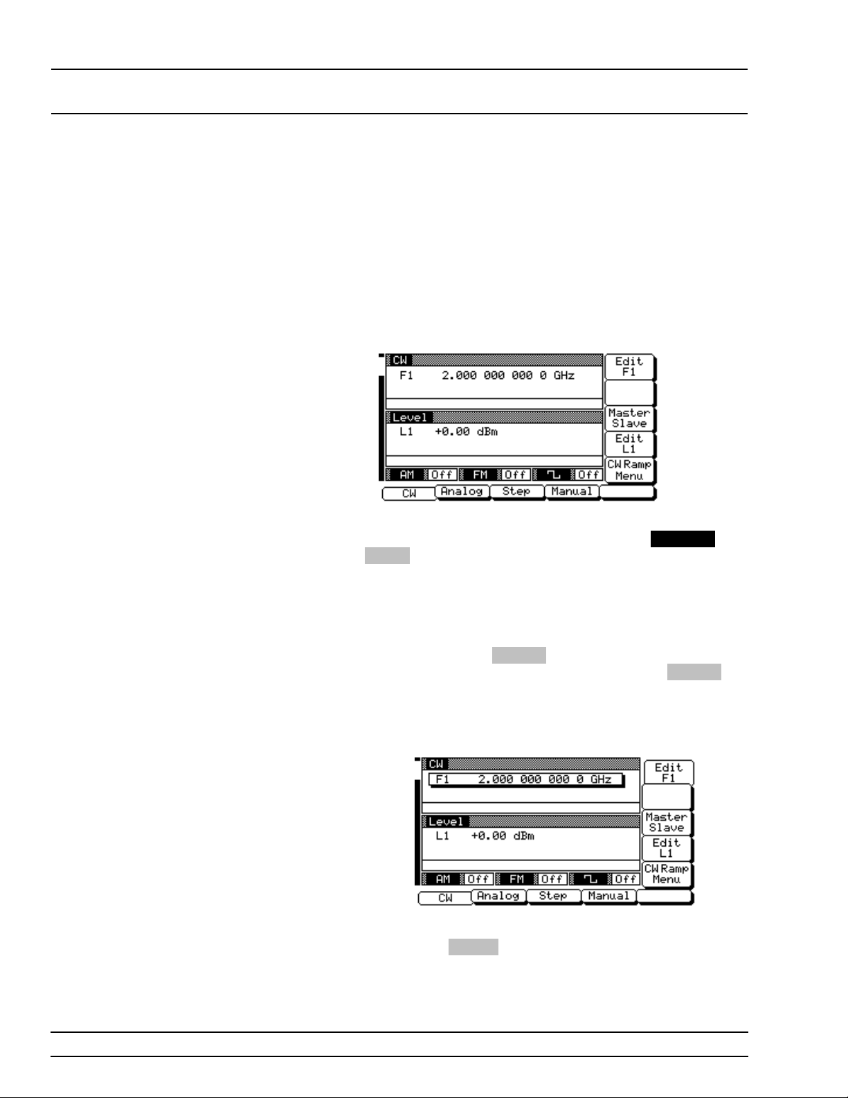
A typical 681XX B men u display (below) is used throu ghou t the data
entry instruc tions. At this menu di splay, you can edit both the CW frequency and the outpu t power level parame ters.
If you wish to follow along on your synthesizer, you can obtain this
same menu display by resetting your instrumen t (pre ss
then press
Reset ).
SYSTEM ,
Opening the
Parame ter
In order for the value of a parame te r to be changed ,
the parameter mus t first be opened.
To open the frequenc y parameter from the abov e
menu, press
changes to show that the menu soft-key
has been pressed and that the frequency parameter
has been open ed . An open parameter i s indic ated by
placing it in a window with a movable cur sor under
its digits.
Only one parameter can be open at a time. If you
press
Edit L1, then the frequency parameter will
close and the power leve l parameter will ope n.
Edit F1 . The menu display now
Edit F1
3-16 681XXB OM
Page 45
LOCAL (FRONT ENTERING
PANEL) OPERATION DATA
Cursor
Control
Key
Rotary
Data
Knob
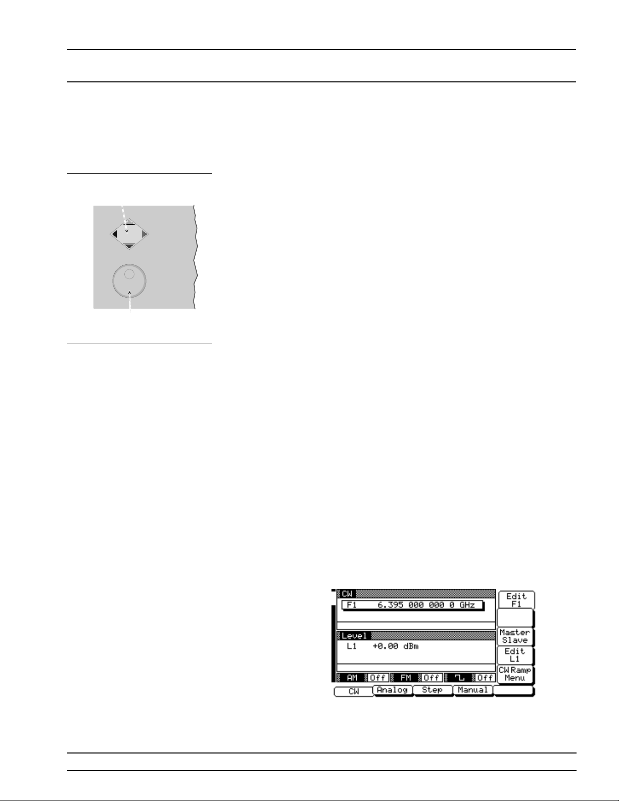
Editing the
Current
Value
To change the curr ent valu e of a parameter by editing, you can use either the cursor control key or the
rotary data knob.
Using the Cursor Control Key
Using the < and > pads of the cursor control key,
move the cur sor und er the digit wh er e you wan t to
begin editing. Then increase or decre a se the value
of the parameter using the ∧ or ∨ pad of the cursor
control key. The unit size of the increase or decrease
that occurs eac h time the ∧ or ∨ pad is pressed is determined by the cursor position .
Using the Rotary Data Knob
You can also increase or decrease the value of the parameter using the rotar y data kn ob. Once you have
positioned the cursor under the digit where you
want to begin editing, slowly turn the knob cloc k wise or counter-c loc k wise to inc rease or dec rease
the value of the parameter by the uni t size. Turning
the knob rapidly changes the v alue of the parameter in larger steps.
Using a Set Incr emen t
When editing frequ enc y, power level, and time parameters, you can incre ase or decr ease the par am eter’s value by a set amount each time the ∧ or ∨ pad
is pressed or the rotary data knob is turned clo ckwise or counter-c loc k wise. For instruc tions on setting the increment size, refe r to the System
Configuration section of this chapter.
Now , try changing the current value of the CW frequency displayed on your synthesizer from 2.0 GHz
to 6.395 GHz. Use both the cursor co ntr ol key’s ∧
and ∨ pads and the rotary data kno b to make the
value chang es. Wh en you are fin ishe d, you r menu
display should look like the example below.
681XXB OM 3-17
Page 46
LOCAL (FRONT ENTERING
PANEL) OPERATION DATA
To close the open parameter when you are finishe d
editing , pre ss
tion.
Edit F1 or make another menu selec-
Clear
Entry
Key
CLEAR
ENTRY
4
1
0
Back
Space
87
5
2
Keypad
Key
BACK
SPACE
9
6
3
Terminator
Keys
GHz
Sec
dBm
MHz
ms
dB
kHz
m
s
STEPS
Hz
ns
ADRS
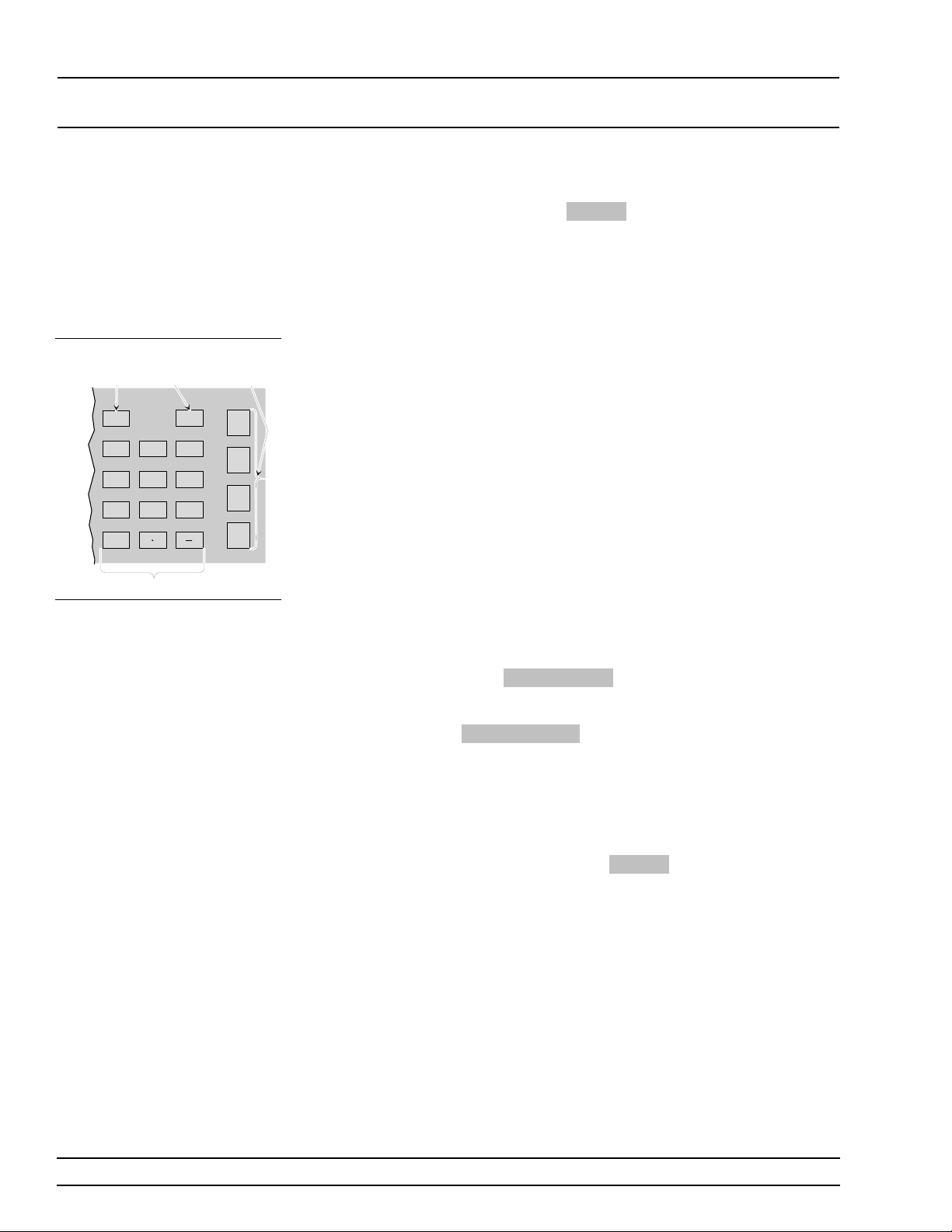
Enterin g a
New Value
To change the curr ent valu e of a parameter by entering a new value for the parameter, use the data entry keypad and termin a tion keys.
As soon as you pr e s s one of th e ke ys on the data entry keypad, the cur rent par ameter display clears for
entry of a new value . Enter the new value for the pa rameter, then press the appropr iate termin ator key
to store it in memory. If the entered value is outside
the allowable rang e of the open par ameter, the entry is not accepted and the previous value for the parameter is displayed.
NOTE
A frequency entry may be terminated in
GHz, MHz, kHz, or Hz; howev er, it is always displayed on the data display in
GHz. A time entry may be terminated in
Sec, ms, µs, or ns; however it is always
displayed on the data display in Sec.
If you make an error durin g data entry, either (1)
press
BACK SPACE to delete the entry on e char acter at a time starting from the last character entered, or (2) delete the entire entry by pressing
CLEAR ENTR Y . Then, reenter the corr ect value .
Now , try entering a new value for the CW frequency
displayed on you r synth esizer using the data entry
keypad and termin ation keys.
To close the open parameter when you are finishe d
entering data, press
Edit F1 or make another
menu selection.
3-18 681XXB OM
Page 47
LOCAL (FRONT CW FREQUENCY
PANEL) OPERATION OPERATION
3-7
Refer to Chapter 7, paragraph 7-2
for Master-Slave mode operating
instructions.
CW FREQUENCY
OPERATION
NOTE
One of the sweep generator’ s major functions is to produce discrete
CW frequencies across the frequency range of the instrument. The following parag r aph s describe ho w to place the 681XXB in the CW frequency mode, select a CW freque nc y and pow er level f or outpu t, and
activate the CW ramp. Use the CW Frequ ency Mode men u map (Cha pter 4, Figure 4-2) to follow the menu sequ ence s.
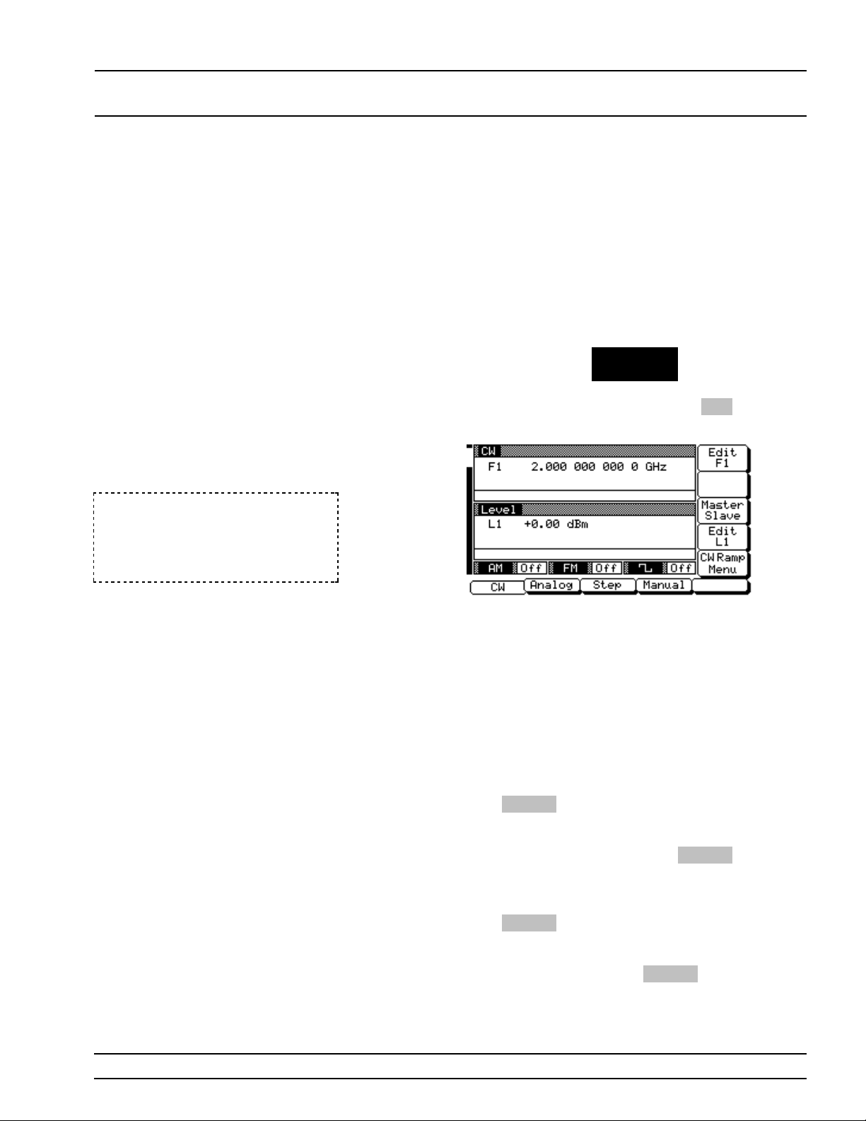
Selecting
CW Mode
To place the 681XXB in the CW frequen cy mode,
press the main menu key
CW/SW EEP
SELECT
At the resulting menu display, press
Menu (below) is displayed.
CW . The CW
Selecting
a CW
Frequency
NOTE
When the sweep generator is rese t, it
automatically come s up o per ating in the
CW frequency mode.
There are seve ral w ays to select a CW frequ en cy for
output. You can (1) edit the cu r r en t frequency, (2) en ter a new freque ncy, or (3) select one of the 20 preset frequency parameter s.
Editing the Current Frequency
Press
Edit F1 to open the frequenc y parameter,
then edit the current CW frequency using the cursor control key or the rotary data knob. To close the
open frequency parameter, press
another menu selection.
Entering a New Frequency
Press
Edit F1 to open the frequenc y parameter,
then enter the n ew CW frequ en c y usin g the key p ad
and appropriate ter minator key. T o close the open
frequency parameter, press
other menu selec tion.
Edit F1 or make
Edit F1 or make an-
681XXB OM 3-19
Page 48
LOCAL (FRONT CW FREQUENCY
PANEL) OPERATION OPERATION
Selecting a Preset Frequency
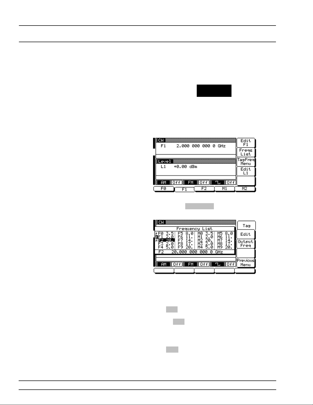
To select one of the preset frequen cie s for outp ut,
press the main menu key
FREQUENCY
CONTROL
The CW Frequen cy Contro l menu (below ) is displayed. This menu lets you (1) select preset frequ en cies F0, F1, F2, M1, or M2 for output, (2) go to the
frequenc y list menu, or (3) go to the tagged frequ encies menu.
Frequen cy Li st– To go to the Frequenc y List menu
(below), press
tag,edit, or output a frequ en cy from the li st.
Use the cursor contr ol key to select a frequ en cy
from the frequency list. The selected frequency is
highligh ted in rever se vide o and display ed in full below the frequenc y list.
Press
Tag to mark a selected frequency (place an F
in front of it). If the frequen c y is alread y tagged ,
pressing
selected frequen cies lets you qu ick ly swi tch betwee n
them using the scan key s of the Tagged Frequ enc ie s
menu.
Freqs List . This menu lets you
Tag will untag it (remov e the F ). Tag g ing
Press
Edit to edit the selected frequency or enter a
new frequ en cy.
3-20 681XXB OM
Page 49
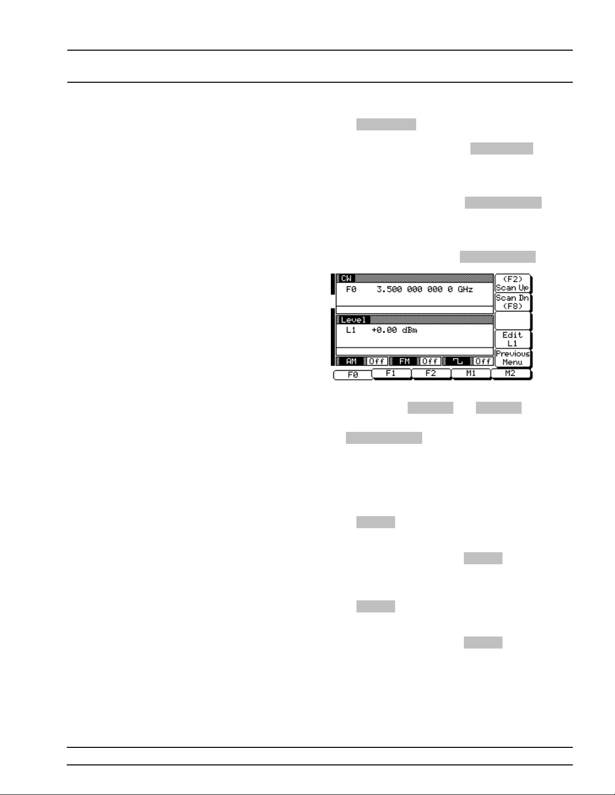
LOCAL (FRONT CW FREQUENCY
PANEL) OPERATION OPERATION
Press Output Freq to output the selected frequency.
This frequ en cy i s outpu t until yo u selec t another frequency from the list and press
the frequency list, the output frequency selection is
marked by a black square or, if tagged, an F h ighlighted in rever se video.
Output Freq . On
Selecting a
Power Lev el
When you are finished, press
turn to the CW Frequency Contr ol men u display.
Scannin g Tagged Frequencies–To go to the
Tagged Frequencies me nu (below ) from the CW Frequency Control menu, press
This menu lets you select the tagged frequ enc ies for
output using the
Return to the CW Frequ en cy Con trol men u by pressing Previous Menu .
While in the CW frequency mode, you can edit the
current CW frequency output power level or enter a
new output power level.
Scan Up and Scan Dn keys.
Previous Menu to re-
Tag Freq Menu .
Editing the Current Power Level
Press
Edit L1 to open the power lev el parame ter,
then edit the current power level using the cursor
control key or rotary data kno b. To close the open
power level par ameter, press
other menu selec tion.
Entering a New Power Level
Press
Edit L1 to open the power lev el parame ter,
then enter the n ew power lev el usin g the keyp ad
and appropriate ter minator key. T o close the open
power level par ameter, press
other menu selec tion.
Edit L1 or make an-
Edit L1 or make an-
681XXB OM 3-21
Page 50
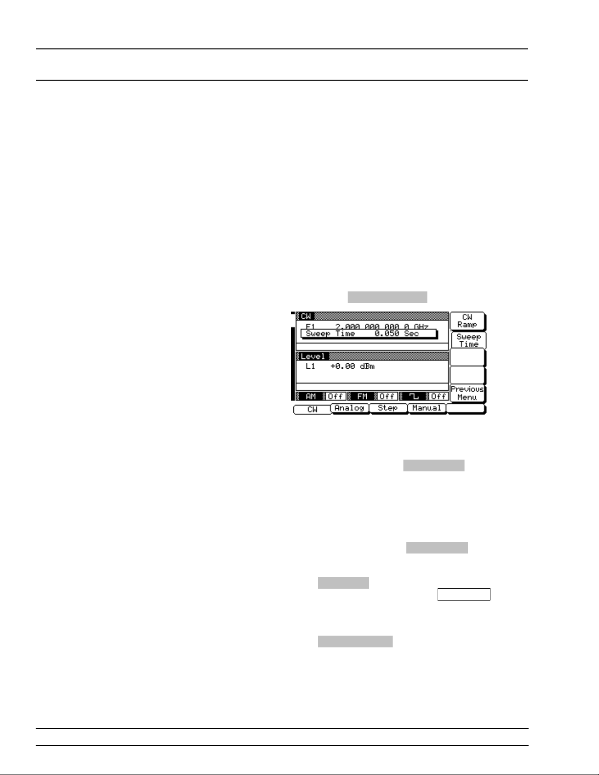
LOCAL (FRONT CW FREQUENCY
PANEL) OPERATION OPERATION
NOTE
You can al so selec t any of the pr eset
power levels or a power level sweep for a
CW frequency. For instructions, refer to
the Fixed Power Level Operation and
Power Level Sweep Operation section s o f
this chapter.
CW Ramp When active, the sweep generator’ s CW ramp pro-
vides a repetitive 0V to 10V ramp output to the rear
panel HORIZ OUT BNC connec to r an d AUX I/O con-
nector. The CW ramp is used to drive a scalar analyzer display.
To go to the CW Ramp menu (below) from the CW
menu, press
CW Ramp Menu .
This menu lets you set the ramp speed and turn the
CW ramp on/off.
To set ramp speed, press
time parameter opens for editin g. Edit the curre nt
sweep time using the cur sor con trol ke y or rotary
data knob or enter a new sweep time using the key
pad and approp riate ter mination key. The sweep
time entered must be in the range of 30 ms to
99 sec. To close the open sweep time parameter
when you are done, press
other menu selec tion.
Press
CW Ramp to turn the CW ramp on. While
the CW ramp is on, the message
pears on the right side of frequ enc y title bar on all
CW menus.
Press
Previous Menu to return to the CW menu.
Sweep Time . The sw eep
Sweep Time or make an-
CW Ramp ap-
3-22 681XXB OM
Page 51
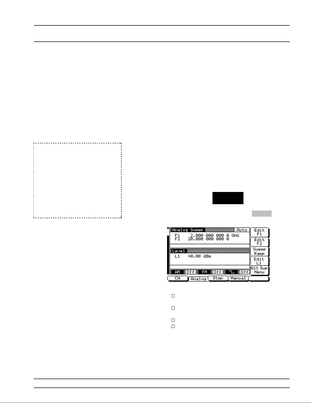
LOCAL (FRONT SWEEP FREQUENCY
PANEL) OPERATION OPERATION
3-8
In 681X5B models performing analog sweeps between 0.5 and
2.2 GHz, the sweep is phase-lock
corrected as follows. For sweep
widths of >25 MHz, phase-lock correction occurs at both the start and
stop frequencies and at each bandswitch point. For sweep widths of
≤25 MHz, o nly th e center f reque ncy
of the sweep is phase-lock corrected.
SWEEP F REQUENCY
OPERATION
NOTE
The sweep gen er a tor can g ener a te broad (fu ll ran g e) an d nar r ow band
sweeps acro ss the frequ en c y rang e of the ins trumen t. Th e 681XX B ha s
three sweep fre que ncy modes—an alog swee p, step sweep , and manu a l
sweep. The following paragraphs describe how to select each sweep frequenc y mode, a sw eep ran ge, an ou tpu t pow er lev el, a sweep trigg er,
and frequen c y mar k ers. U se the An alog Sweep , Step Swee p, an d Ma n ual Sweep Freque ncy Mode menu maps (Chapter 4, Figur es 4-3, 4-4,
and 4-5) to follow the menu sequen ces.
Selecting
Analog
Sweep Mode
In analog sweep fr equ enc y mode, the sweep ge nerator’s output frequency is swept between selected
start and stop frequenc ies. When the sweep width is
>100 MHz, the sweep is phase-lock corr ec ted at
both the start and stop freque ncies and at each
band-switc h point. Wh en the sweep width is
≤100 MHz, only the cen ter frequency of the sweep is
phase-loc k correc ted.
To place the 681XXB in analog sweep frequen cy
mode, press the main menu key
CW/SW EEP
SELECT
At the resulting menu display, press
Analog Swee p Men u (below ) i s then displayed.
Analog . The
This menu lets you perform the following:
Select a sweep range (ed it the sweep s tart and
stop frequency parameters).
Go to the sweep ramp menu (set the sweep
time and select a sweep trigger).
Select an output power level for the sweep .
Go to the alternate sweep menu.
681XXB OM 3-23
Page 52
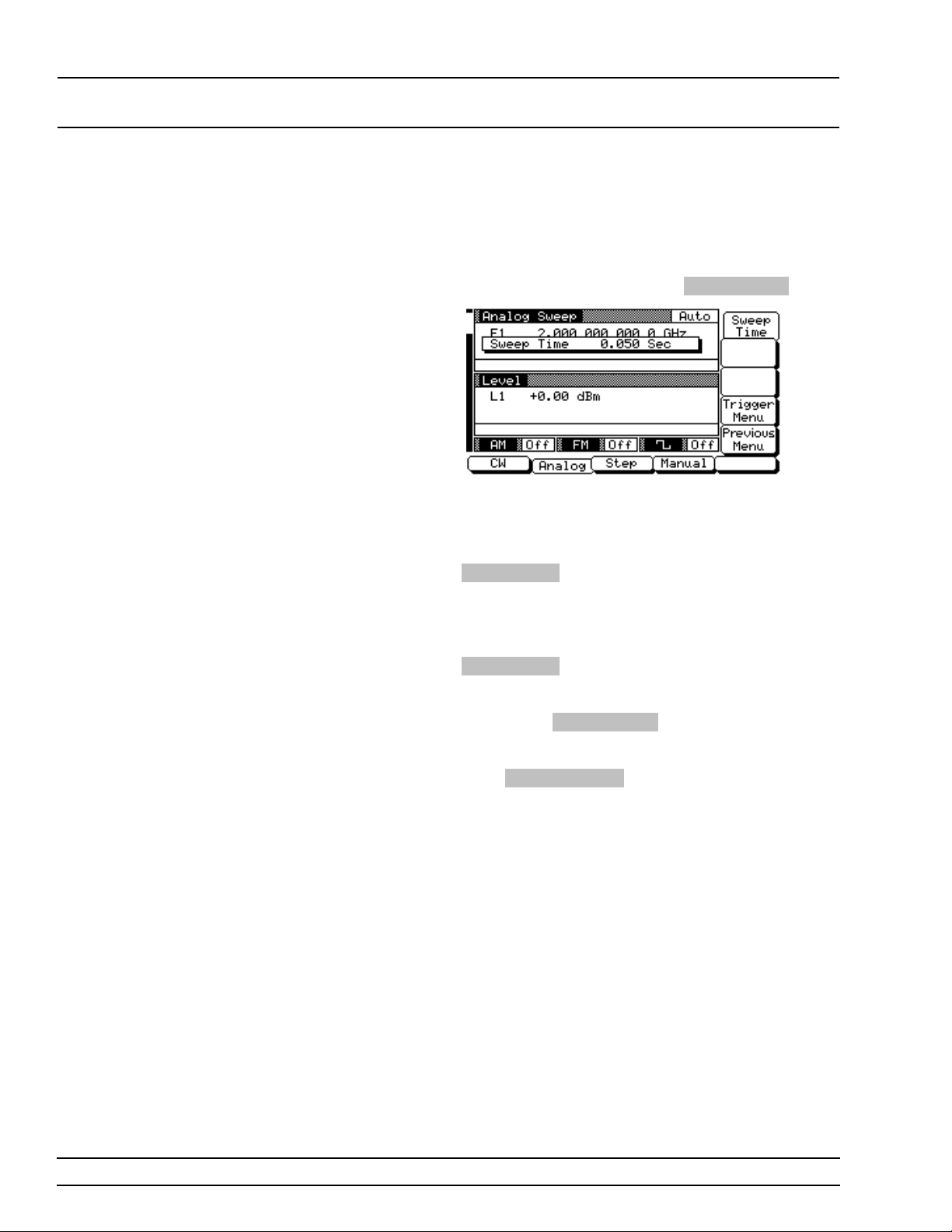
LOCAL (FRONT SWEEP FREQUENCY
PANEL) OPERATION OPERATION
Setting the
Analog
Sweep Time
The duration of the analog sweep can be set for any
time in the range of 30 ms to 99 sec. The sweep time
parameter is set from the sweep ramp menu.
To go to the Analog Sweep Ramp men u (below ) from
the Analog Swe ep men u , pre ss
This menu lets you set the sweep time and go to the
trigger men u.
To open the sweep time paramete r for editin g, pre ss
Sweep Time . Edit the cur rent swee p time usin g
the cursor control key or the rotary data knob or en ter a new sweep time using the key pad and appropriate termination key. To close the open sweep time
parameter onc e you have set the desired time, pre ss
Sweep Time or make an othe r menu selection .
Sweep Ramp .
To go to the Analog Swee p Trigger menu from this
menu, press
scribed on the next page .
Press
Previous Menu to return to the Analog
Sweep menu.
Trigger Menu . Sweep trigger is de-
3-24 681XXB OM
Page 53
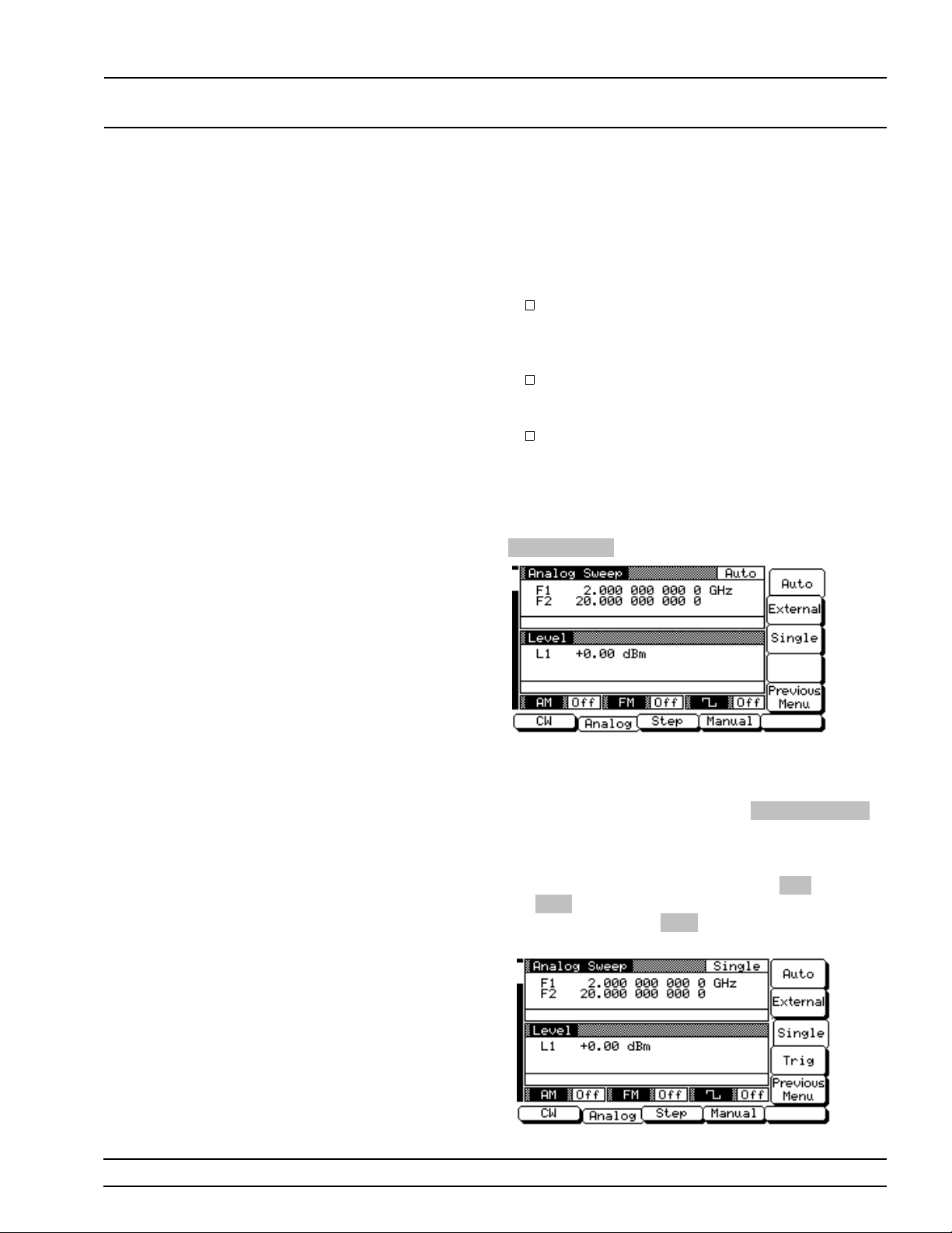
LOCAL (FRONT SWEEP FREQUENCY
PANEL) OPERATION OPERATION
Selecting a
Sweep
Trigger
The 681XXB pr ov ides sweep triggering for analog
frequency sweep, step frequency sweep, and CW
power sweep. The sweep generator has three modes
of sweep triggerin g , each selectable f rom the trig ge r
menu. The following is a description of each mode.
Auto (Auto matic)–The sweep continually
sweeps from its start frequency or power level
to its stop frequency or power level with optimal retrace time.
External–Th e swee p rec u r s when trig ger ed by
an external TTL-c ompatible clo ck pulse to the
rear panel AUX I/ O connector.
Single–A single sweep starts when the trigger
key is pressed. If a sweep is in progress when
the key is pressed, it aborts and resets.
To go to the Analog Swee p Trig ger me nu (be low )
from the Analog Sweep Ramp men u, press
Trigger Menu .
To select a sweep trigger mode , pres s its menu softkey. A message showing the sweep trigger mod e selected appear s on the right side of frequ en cy title
bar. When you are finished, press
to return to the Analog Sw eep Ramp menu.
If you selec t the sin gle sweep trigger mo de, the
menu display adds the menu sof t-key
ing
Trig starts a single sweep. If a single sweep is
in progress, pressing
abort and reset.
Trig causes the sweep to
Previous Men u
Trig . Press-
681XXB OM 3-25
Page 54
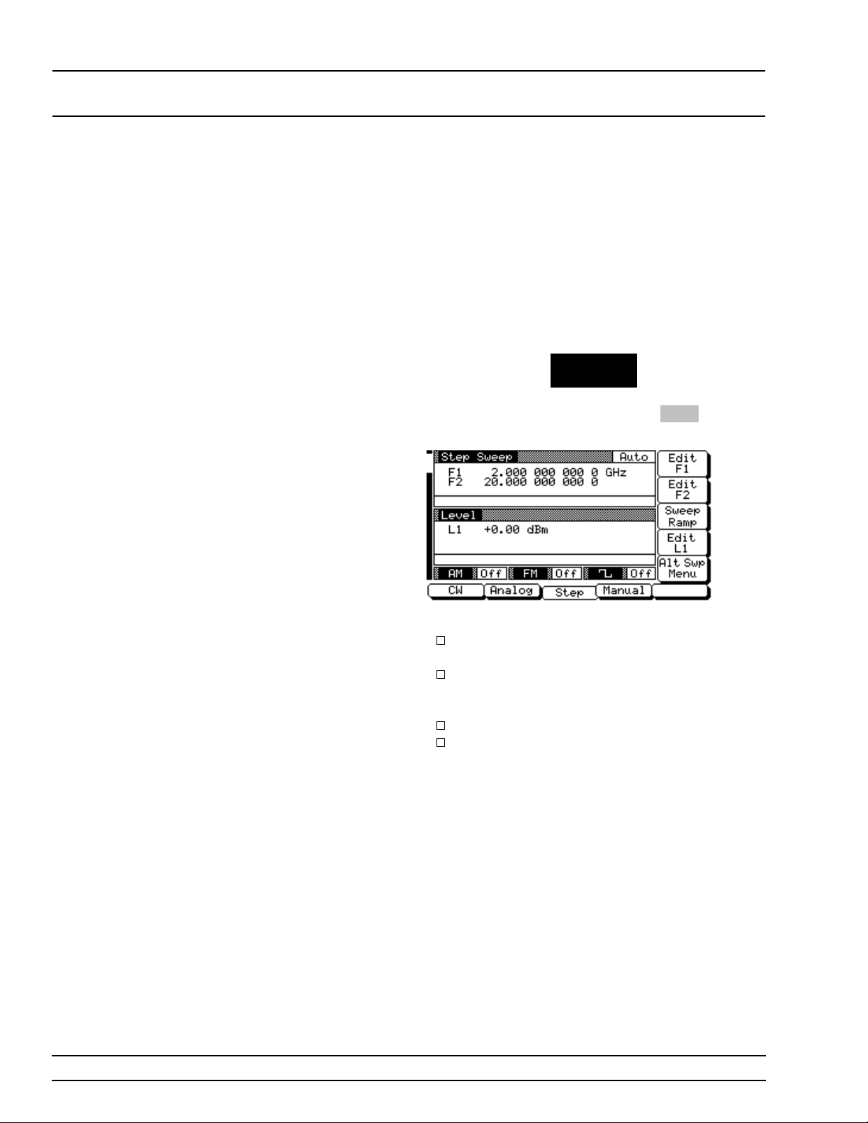
LOCAL (FRONT SWEEP FREQUENCY
PANEL) OPERATION OPERATION
Selecting
Step Sweep
Mode
In step sweep frequency mode, the output frequency
changes in discrete, syn th esized step s between selected start and stop frequen cie s. Step sweeps can
be from a high frequency to a low frequency and
vice versa. The step size or number of steps between
the start and stop frequenc ies and the dwell timeper-step are contr ollable from a step sweep menu .
To place the 681XXB in step sweep fre que ncy mo de,
press the main menu key
CW/SW EEP
SELECT
At the resulting menu display, press
Step Sweep Menu (below) is then displayed .
Step . The
This menu lets you perform the following:
Select a sweep range (ed it the sweep s tart and
stop frequency parameters).
Go to the sweep ramp menu (set the dwell
time-per-step, the step size or number of steps,
and select a sweep trigger).
Select an output power level for the sweep .
Go to the alternate sweep menu.
3-26 681XXB OM
Page 55
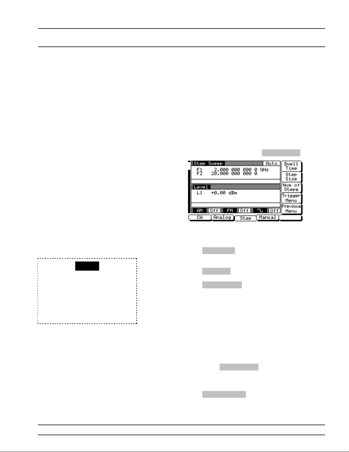
LOCAL (FRONT SWEEP FREQUENCY
PANEL) OPERATION OPERATION
Setting Step
Size and
Dwell T ime
There are two ways to set the size of each step of
the step sweep—set the step size or set the number
of steps. The step size range is 1 kHz to the full frequency range of the sweep generator (0.1 Hz to full
frequency range with Option 11); the number of
steps range is 1 to 10,000. The dwell time-per-step
of the step sweep c an be set for any time in the
range of 1 ms to 99 sec. The step size and dwell
time-per-step parameters are set from the step
sweep ramp menu.
To go to the Step Sweep Ramp menu (below) fro m
the Step Sweep men u, pr e ss
This menu lets you set the dwell time, the step size,
the number of steps, and go to the trigger men u.
Sweep Ramp .
RANGE
This error message is displayed
when (1) the step size value entered
is greater than the sweep range or
(2) the number of steps entered results in a step size of less than 1 kHz
(0.1 Hz with Option 11). Entering a
valid step size will clear the error.
Press
Dwell Time to open the dwell time-per-step
parameter.
Press
Step Size to open the step size parameter.
Num of Steps to open the number of step s
Press
parameter.
Open the parameter you wi sh to change, then edit
the current value using the cur sor contr ol key or the
rotary data knob or enter a new valu e using the key
pad and approp riate ter mination key. When you
have finished setting the ope n parameter, close it by
pressing its menu soft-key or make another menu
selection.
To go to the Step Sweep Trigger menu from thi s
menu, press
you select a sweep trigger (previou sly described on
page 3-25).
Press
Previous Menu to return to the Step Sweep
menu.
Trigger Menu . The trigger menu lets
681XXB OM 3-27
Page 56
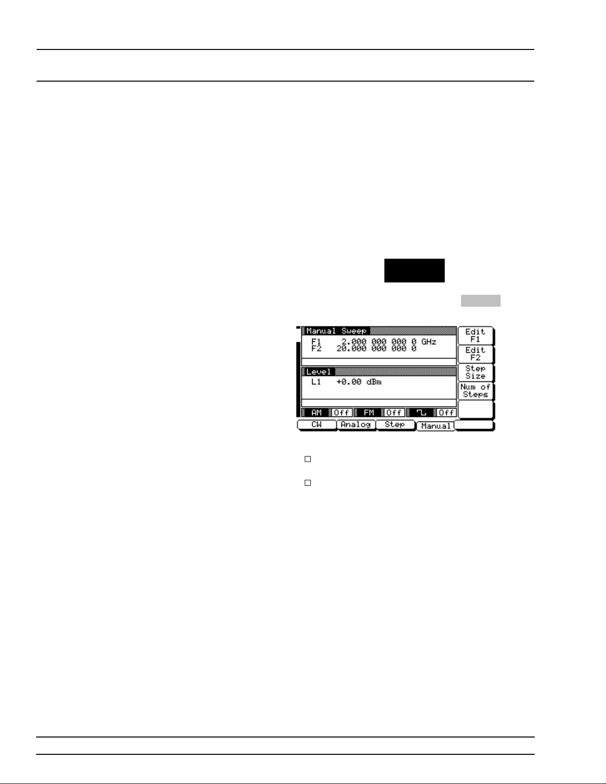
LOCAL (FRONT SWEEP FREQUENCY
PANEL) OPERATION OPERATION
Selecting
Manual
Sweep Mode
In manual sweep fr equ en cy mode, the outp ut frequency can be manually tuned in phase-lo cked
steps between the selected start and stop frequ encies using the rotary data knob. As the knob is
turned, the current output frequency is displayed on
the data display as Fm. The step size or number of
steps between the start and stop frequenc ies are
controllable from th e manual swee p menu .
To place the 681XXB in manu al sweep frequ en c y
mode, press the main menu key
CW/SW EEP
SELECT
At the resulting menu display, press
Manual Sweep menu (below) is then displayed.
Manual . The
This menu lets you perform the following:
Select a sweep range (edi t the start and stop
frequency par ameters).
Set the step size or number of steps (previously described on page 3-27).
3-28 681XXB OM
Page 57
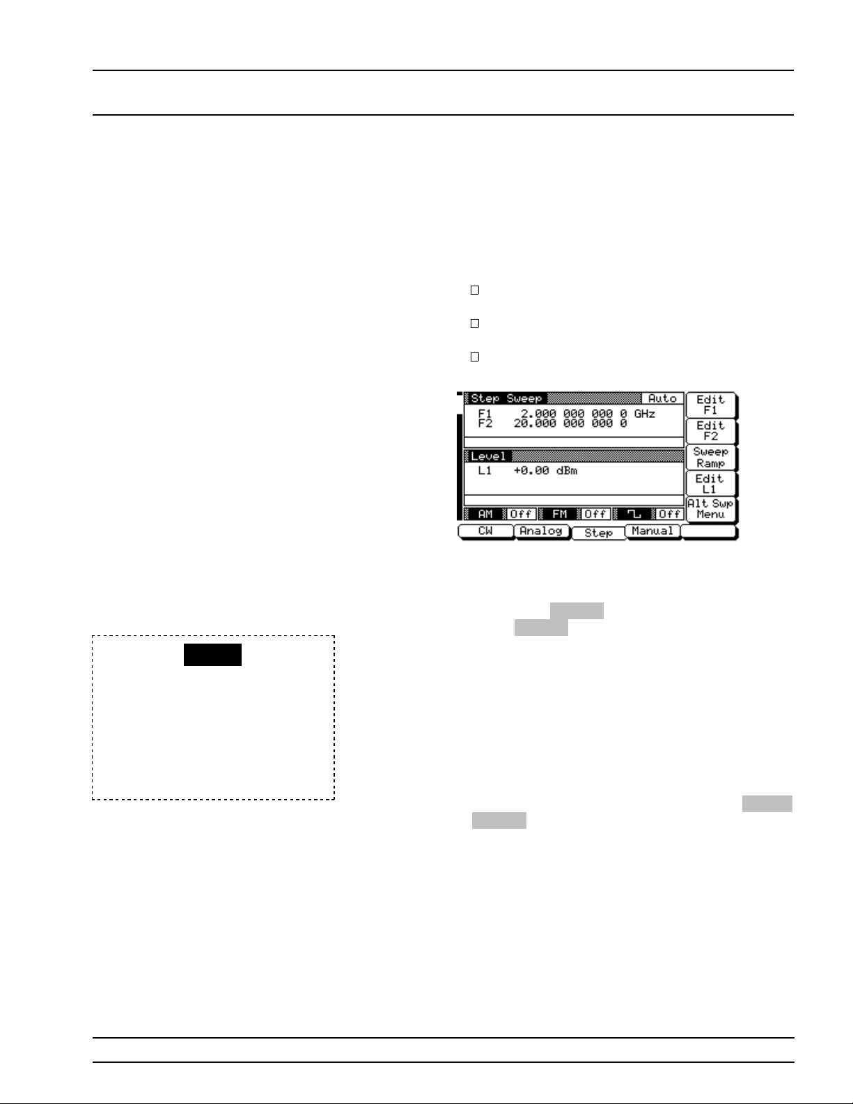
LOCAL (FRONT SWEEP FREQUENCY
PANEL) OPERATION OPERATION
RANGE
This error message is displayed
when (1) the an alog swe ep s tart frequency entered is greater than the
stop frequency, or (2) the dF value
entered results in a sweep outside
the range of the 681XXB. Entering
valid values will clear the error.
Selecting a
Sweep Range
Selecting a sweep range involves choosing a start
and a stop frequenc y for the frequ en c y sweep. The
sweep range selection process is identical for all
sweep frequency modes (analog, step, and manual).
There are seve ral w ays you can selec t a swee p
rang e, in clu d in g :
Editing the current start and stop frequency
parameter values.
Enterin g new start and stop frequ en cy par ameter values.
Selecting one of the preset sweep ran ge pa rameters (F1-F 2, F3-F4, F5-dF, or F6-dF).
Editing the Current Start / Stop Frequencies
To edit the current sweep r ang e s tart by open in g
either the start or stop freque ncy parame ter (in the
display above,
rameter;
ter).
Edit the open frequ ency parameter using th e cu r sor
control key or the rotar y data knob. Wh en you are
finished, close the open parameter by pressing its
menu edit soft-key or by mak ing another menu selection.
Entering Ne w Star t / Stop Freq uen cies
To enter a new sweep ran g e start by open in g either
the start or stop frequenc y parameter (press
or
Edit F2 ).
Edit F1 open s th e start fr equ en c y pa-
Edit F2 open s th e stop frequency parame-
Edit F1
Enter a new frequen c y using the keyp ad and appr opriate terminator key. When you are finished, close
the open parameter by pressing its menu edit softkey or by making ano ther menu selection.
681XXB OM 3-29
Page 58
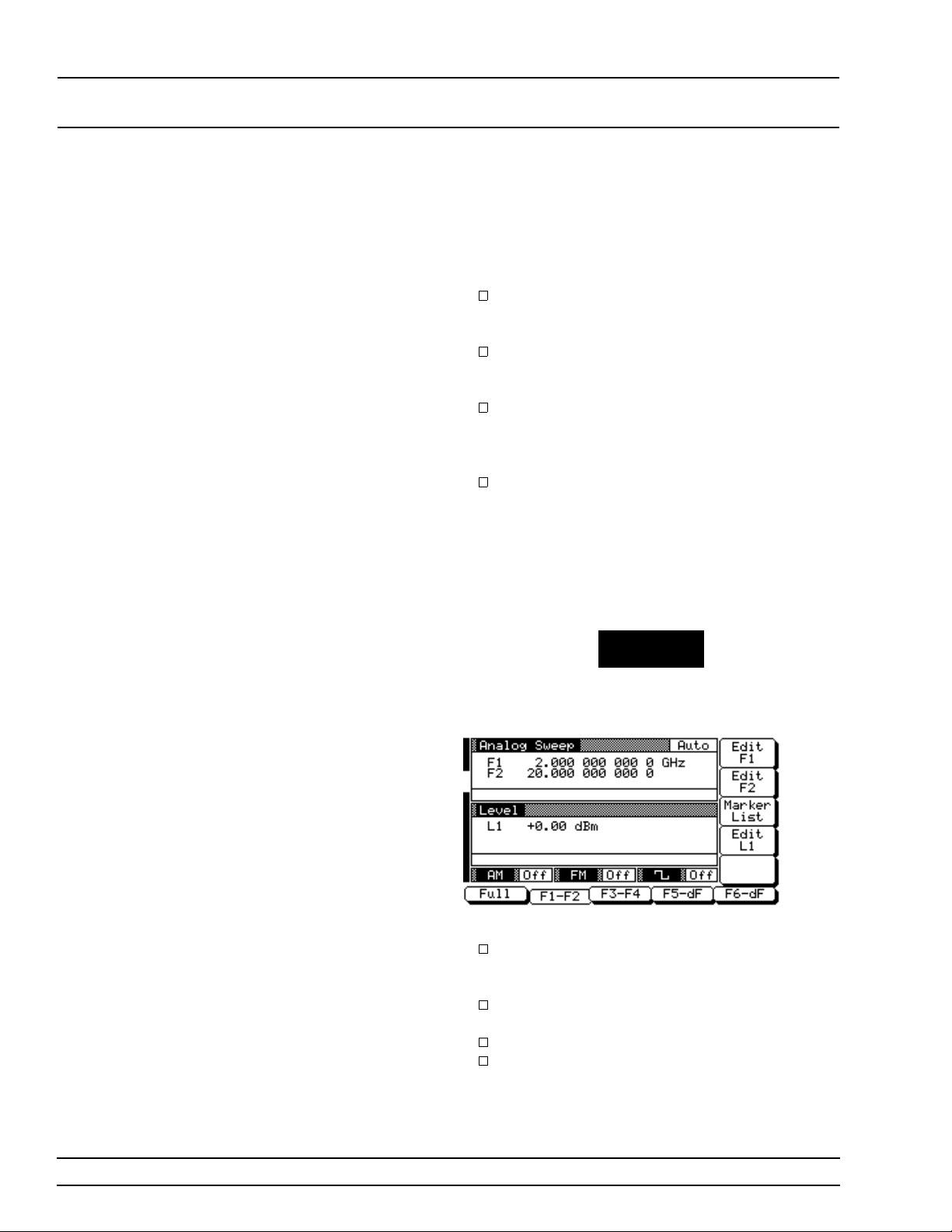
LOCAL (FRONT SWEEP FREQUENCY
PANEL) OPERATION OPERATION
Selecting a Preset Sweep Range
There are four preset sweep ran ge parame ters, selectable in the analog swee p, s tep sweep, and manual sweep freque ncy modes. Th e followin g is a
description of each preset sw eep range .
F1-F2–provides a frequency sweep between
the start frequency, F1, and the stop frequency,
F2.
F3-F4–provides a frequency sweep between
the start frequency, F3, and the stop frequency,
F4.
F5-dF–pr ov ides a symmetric al frequ en cy
sweep about the center frequ en cy, F5. The
sweep width is determined by the dF frequency parameter.
F6-dF–pr ov ides a symmetric al frequ en cy
sweep about the center frequ en cy, F6. The
sweep width is determined by the dF frequency parameter.
To select one of the preset sweep rang es from an y
sweep frequency mode menu, press the main menu
key
FREQUENCY
CONTROL
The Sweep Frequ en cy Contro l menu (below ) is displayed.
This menu lets you perform the following:
Select a full range sweep (Fmin–Fmax ) or one
of the preset sweep ranges for the sweep fr equency mode.
Select the frequenc y parameter s for each preset sweep rang e.
Select an output power level for the sweep .
Go to the marker list menu.
3-30 681XXB OM
Page 59

LOCAL (FRONT SWEEP FREQUENCY
PANEL) OPERATION OPERATION
Setting a Pres et Sweep Rang e –At the men u, select the swe ep ran g e ( F1-F 2 , F3- F4, F5-dF, or
F6-dF) that you wish to set. The menu then display s
the current frequ en cy par ameter s for the selected
sweep range. Now, use the menu edit soft-ke ys to
open the frequency parameters for editin g.
Edit the current frequency parameters or enter new
frequenc y parame ter value s for the sweep ran ge. To
close the open frequ en c y parameter when you are
finished, press its menu edit soft-ke y or make another menu selec tion.
You can set all the preset sweep ranges in this manner.
Selecting a
Power Lev el
While at the Sweep Frequency Control menu, you
can edit the curre nt ou tp ut pow er leve l or ente r a
new output power level for the frequency sweep.
Editing the Current Power Level
Press
Edit L1 to open the power lev el parame ter,
then edit the current power level using the cursor
control key or rotary data kno b. To close the open
power level par ameter, press
other menu selec tion.
Entering a New Power Level
Press
Edit L1 to open the power lev el parame ter,
then enter the n ew power lev el usin g the keyp ad
and appropriate ter minator key. T o close the open
power level par ameter, press
other menu selec tion.
You can al so selec t any of the pr eset
power levels fo r a frequency sweep or a
power level step for analog and step
sweeps. For instruc tion s, re fer to the
Fixed Power Lev el Op eration and Power
Level Sweep Op er a tio n sectio ns of thi s
chapter.
Edit L1 or make an-
Edit L1 or make an-
NOTE
681XXB OM 3-31
Page 60
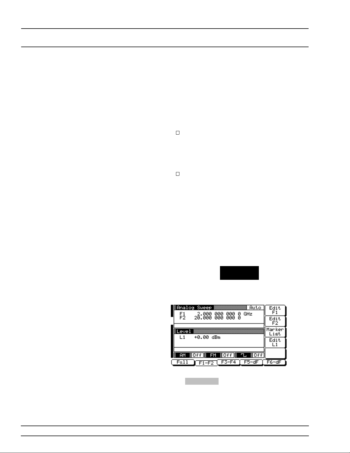
LOCAL (FRONT SWEEP FREQUENCY
PANEL) OPERATION OPERATION
Frequency
Markers
The sweep gen era tor prov ides up to 20 indepen den t,
pre-settable markers, F0-F9 and M0-M9, that can
be used in the analog and s tep sweep frequen c y
modes for precise frequency identification. Marker
frequenc y accu rac y is the same as sweep freque ncy
accurac y. The markers are visible on a CRT display.
The 681XXB gener ates two types of mark ers.
V ideo Marker–produces a pulse on a CRT display at each marker frequency. The video
marker is either a +5V or a –5V pulse at the
rear panel. The polar ity of the video mark er
pulse is selectable from a system config uration
menu.
Intensity Marker–produces an intensified
dot on a CRT display at each marker frequency. Intensity mar ker s are only available
in the analog sweep frequency mode and are
obtained from a momentary dwell during the
sweep at each marker frequency.
To output markers dur in g a sweep you must first select (tag) the marker frequencies from the Marker
List menu, then turn on the marker output.
To go to the Marker List menu from an analog or
step sweep frequen cy men u, pre ss
FREQUENCY
CONTROL
The Sweep Frequ en cy Contro l menu (below ) is displayed.
To go to the Marker List menu from this menu,
press
Marker List . The Marker List menu, shown
on the next page, is displayed. This menu lets you
tag or edit marker list frequencies and turn the
mark ers on/off.
3-32 681XXB OM
Page 61
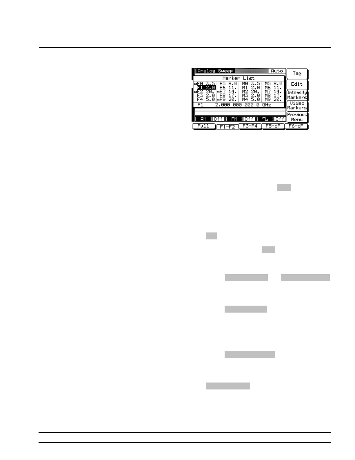
LOCAL (FRONT SWEEP FREQUENCY
PANEL) OPERATION OPERATION
Use the cursor contr ol key to select a frequ en cy parameter from the marker list. The selec ted fre quency par ameter is highlighted in reverse v ideo
and displayed in full below the marker list.
Editing a Mark er Li st Freq uen cy
If you want to chang e a selected mar ker li st frequency parameter’s value, press
frequency parameter, then edit the current frequency or enter a new frequency.
Edit to open the
Tagging a Marker List Frequency
Only frequenc ies on the marke r list that have been
tagged can be outpu t as marker s durin g a sweep .
Press
Tag to tag a selected frequency parameter
(place an m in front of it). If a frequency parameter
is already tagged, pressing
move the m).
Activating Markers
The soft-keys
toggle the marker s on an d off.
V ideo Marker s–To output the tagged mar ke r frequencies as video mark er s durin g an analog or step
sweep, pres s
displayed on the CRT for all tagged mark er frequen cies that are within the sweep fre que ncy rang e.
Intensity Markers–(only available in analog
sweep frequency mode) T o ou tput th e tagged marker
frequenc ies as intensity marke rs du rin g an analo g
sweep, pres s
will be displayed on the CRT for all tagge d mark er
frequenc ies that are within the analog swe ep frequency ra nge.
Video Markers and Intensity Markers
Video Markers . Video markers will be
Intensity Markers . Intensity markers
Tag will untag it (re-
Press
Previous Menu to return to the Sweep Frequency Control menu.
681XXB OM 3-33
Page 62
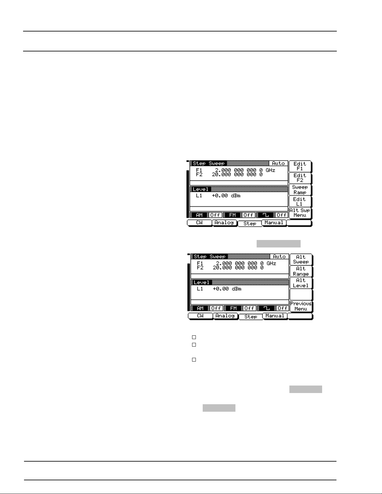
LOCAL (FRONT SWEEP FREQUENCY
PANEL) OPERATION OPERATION
Selecting
Alternate
Sweep Mode
In alternate sweep fr equ ency mode, the swee p generator’s output frequency sweeps alternately between any two sweep rang es in analo g sweep or any
two sweep ranges in step sweep. The proc ess of selecting and activ ating the alternate swe ep i s identical for both analog and step sweep frequ en cy modes.
To select the alternate sweep mode for analog
sweeps, start with the Analog Sweep M en u display;
to select the alternate sweep mode for step sweeps,
start with the Step Sweep Men u display (below).
To go to the Alternate Sweep menu (belo w) from the
Step Sweep menu, press
Alt Swp Menu .
This menu lets you perform the following:
Turn the alternate sweep mode on/o ff.
Go to the alternate range men u to select a
sweep range for the alternate sweep.
Go to the alternate level menu to select a
power level for the alternate sweep.
Activat ing the A lt erna te Sweep
The Alternate Sw eep me nu soft-k ey
gles the alternate sweep mode on and off .
Press
Alt Sweep to turn on the al ternate swee p
mode. Notice th at the Alter nate Sw eep men u (on
the following page) chang es to show tha t the alternate sweep is now active.
Alt Sweep tog-
3-34 681XXB OM
Changed: November 1995
Page 63
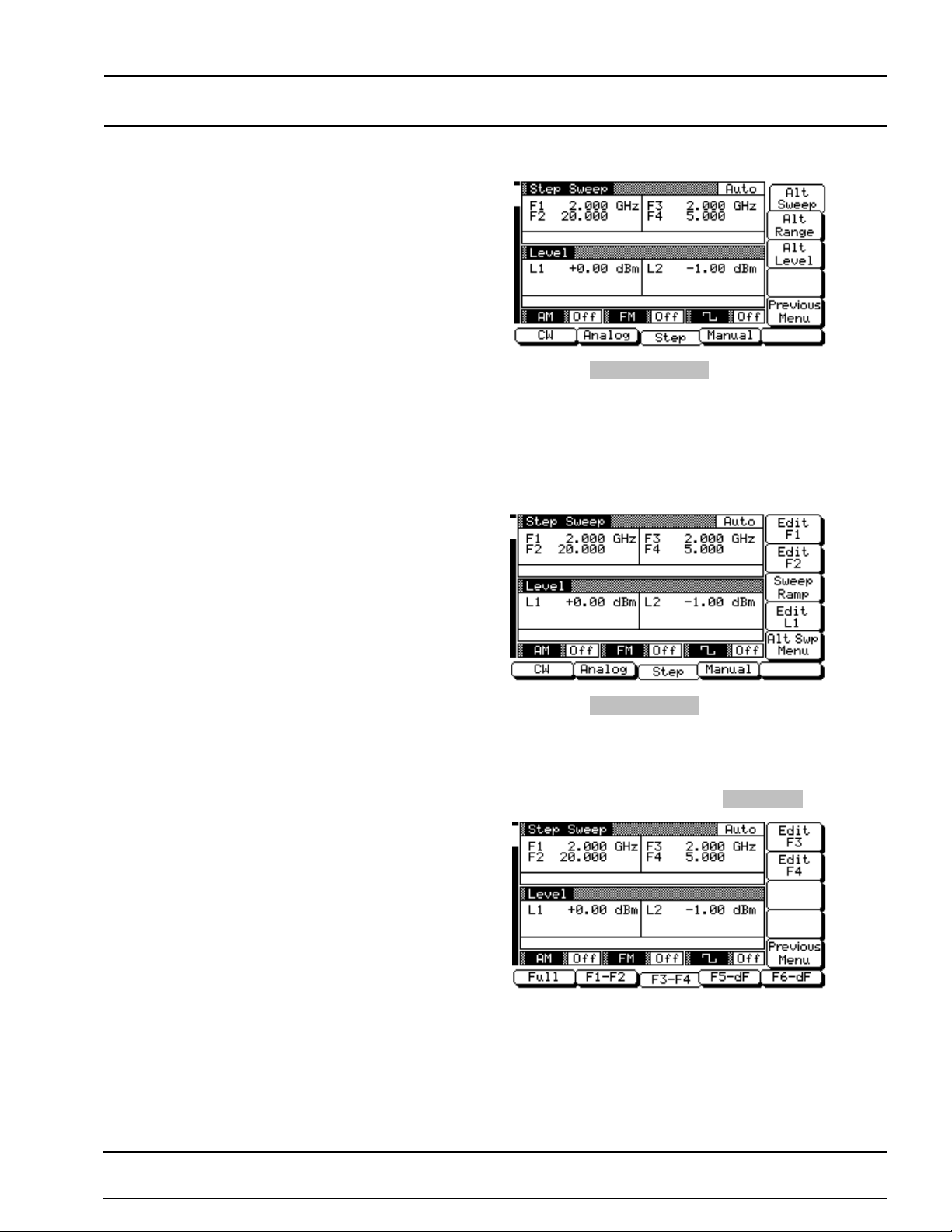
LOCAL (FRONT SWEEP FREQUENCY
PANEL) OPERATION OPERATION
Now, press Previous Menu to return to the Step
Sweep Menu display (or the Analog Sweep Men u
display if oper atin g in analog sweep frequ enc y
mode).
Notice the changes to the Step Sweep Me nu display
(below). These chan g es indic ate that the altern ate
sweep frequency mode is active.
Now, press
nate Sweep menu.
Selecting an A lt ern ate S weep Ran g e
To go to the Alternate Rang e menu (below ) from th e
Alternate Sweep menu, press
Select the alternate sweep ran ge (Full, F1-F2, F3-F4,
F5-dF, or F6-dF). The menu then displays the cu r-
rent freque ncy parame te rs for the selec ted sweep
range. If you wish to chan ge a frequ en cy par ameter,
use the menu edit soft-key to open the parameter,
then edit it.
Alt Swp Men u to r etu rn to th e Alter-
Alt Range .
681XXB OM 3-35
Changed: November 1995
Page 64
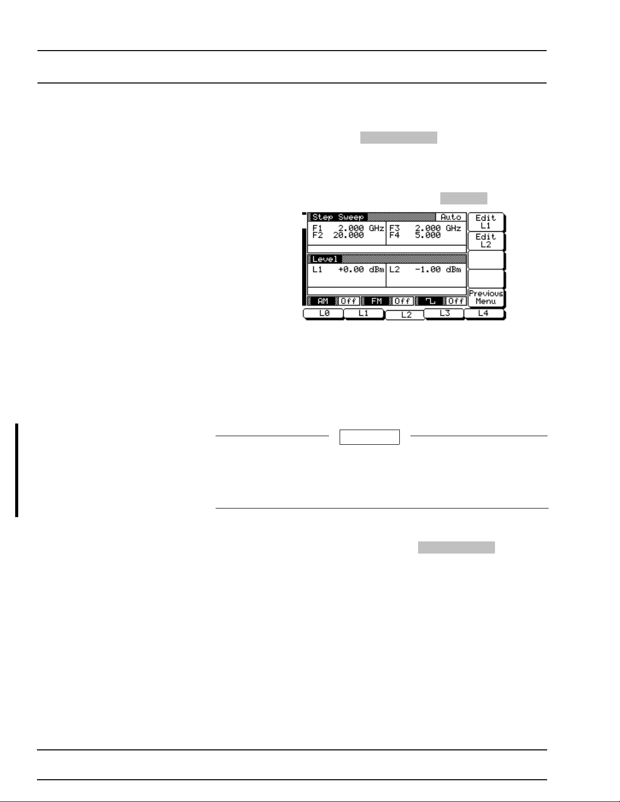
LOCAL (FRONT SWEEP FREQUENCY
PANEL) OPERATION OPERATION
When you are done selec tin g the altern ate swee p
range, press
nate Sweep menu.
Selecting a n A ltern ate Swee p Po wer Lev el
To go to the Alternate Level men u (be low ) from th e
Alternate Sweep menu, press
Select the power level for the alternate sweep ran ge
(L0, L1, L2, L3, or L4). The menu then displays the
current lev el parame ter for the selected power level.
If you wish to change the level, use the menu edit
soft-key to open the parameter, then edit it.
Previous Menu to retu rn to the Alter-
Alt Level .
A men u edit soft-ke y is also provided to let you
change the power level of the main sweep.
CAUTION
Performin g altern a te sweeps usin g power lev els that cr os s
step attenuator switch points can cause excessive wear on
the switches and reduce the life expectancy of the step attenuator.
When you are done selecting the power level for the
alternate sweep ran ge and editin g the powe r level
of the main sweep, press
to the Alternate Sw eep men u.
Previous Men u to return
3-36 681XXB OM
Changed: November 1995
Page 65
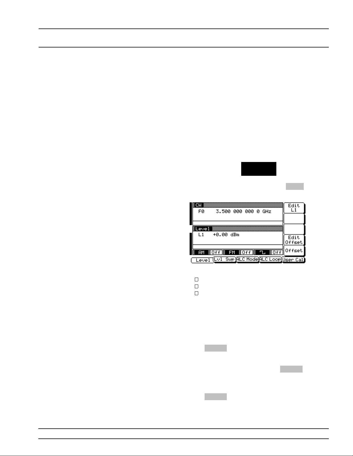
LOCAL (FRONT FIXED POWER
PANEL) OPERATION LEVEL OPERATION
3-9
FIXED POW ER LEVEL OPERATION
The sweep gen era tor prov ides lev eled ou tpu t power over a maximum
range of up to 28 dB (up to 131 dB with Option 2) for CW and sweep
frequency operations. Units with Option 15A provide leveled output
power over a maximu m range of up to 22 dB (up to 125 dB with Option 2). The follow in g par ag r aphs describe how to place the 681X X B in
fixed (no n-sw ep t) powe r lev el mode, select a powe r lev el for outpu t,
and activate lev el offset. Use the Fix ed (Non -Sw ept) Pow er Level
Mode menu map (Chapte r 4, Figure 4-6) to follow the menu sequen c es.
Selecting
Fixed Power
Level Mode
To place the 681XXB in a fixed power level mode
from a CW or sweep (analog , step, or manual) fre quency menu , press the main men u key
LEVEL/ALC
SELECT
At the resulting menu display, press
Level Menu (below) is displayed.
Level . The
This menu lets you perform the following:
Edit the power level par ameter.
Edit the level off se t parameter.
Turn level offset on/off.
Selecting a
Power Lev el
There are seve ral w ays to select a power lev el for
output. You can (1) edit the cu r r en t po we r lev el, (2)
enter a new pow er level, or (3) selec t one of the 10
preset power lev el parameters.
Editing the Current Power Level
Press
Edit L1 to open the power lev el parame ter,
then edit the current power level using the cursor
control key or the rotar y data knob. To close the
open power level parameter, press
another menu selection.
Entering a New Power Level
Press
Edit L1 to open the power lev el parame ter,
then enter the n ew power lev el usin g the keyp ad
Edit L1 or make
681XXB OM 3-37
Page 66
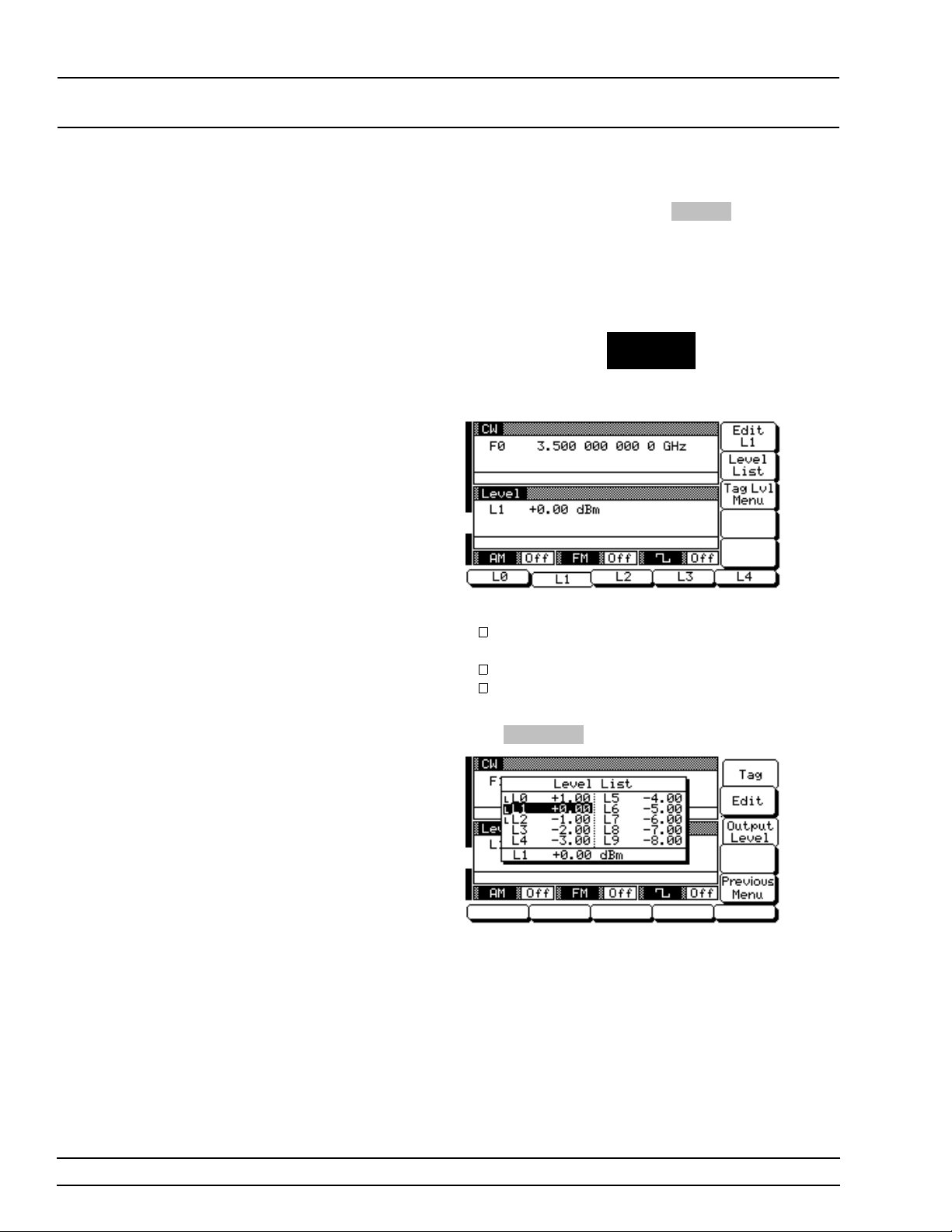
LOCAL (FRONT FIXED POWER
PANEL) OPERATION LEVEL OPERATION
and appropriate ter minator key. T o close the open
power level par ameter, press
other menu selec tion.
Selecting a Preset Power Level
To select one of the preset power leve l s for output,
press the main menu key
LEVEL
CONTROL
The Level Control menu (below) is displayed.
Edit L1 or make an-
This menu lets you perform the following:
Select preset power levels L0, L1, L2, L3, or L4
for output.
Go to the Level List menu.
Go to the T ag ged Lev els menu.
Level List– To go to the Level List menu (below),
press
Level List .
This menu lets you select a powe r level fr om the li st
to tag, edit, or output.
Use the cursor contr ol key to select a power lev el
from the level list. The selected power lev el is highlighted in rever se video and display ed in full below
the level list.
3-38 681XXB OM
Page 67
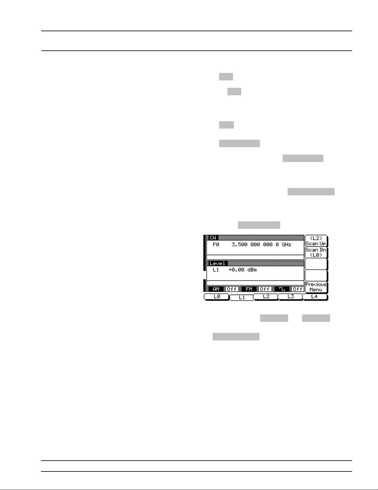
LOCAL (FRONT FIXED POWER
PANEL) OPERATION LEVEL OPERATION
Press Ta g to mark a selected power level (place an
L in front of it). If a power leve l is alread y tagged ,
pressing
selected power levels le ts you quick ly switch be tween them using the scan keys of the Tagged Levels menu.
Press
a new power level.
Press
This power level is output until you select another
level from the list and press
level list, the outpu t power level selection is marked
by a black square or, if tagged, an L high lighted in
reverse video.
Tag will untag it (remov e the L ). Tag g ing
Edit to edit the selected power level or enter
Output Level to output the selected level.
Output Level . On the
When you are finished , press
turn to the Level Control men u display.
Scanning Tagged Levels–To go to the T ag g ed Lev els menu (show n belo w) from the Level Control
menu, press
This menu lets you select the tagg ed powe r level s
for output using the
Return to the Level Con tro l menu di splay by pressing
Previous Men u .
Tag Lvl Menu .
Scan Up and Scan Dn keys.
Previous Men u to re-
681XXB OM 3-39
Page 68
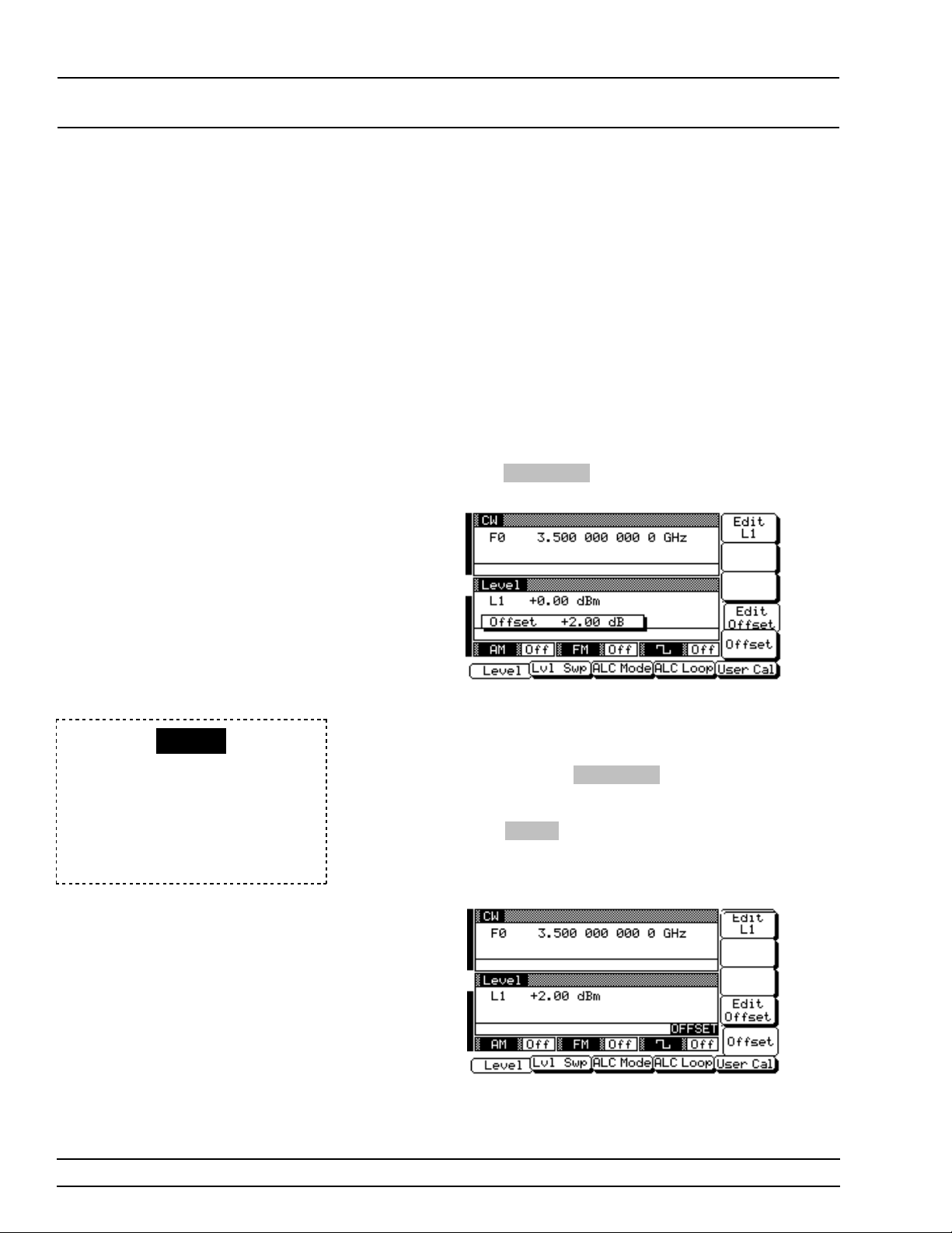
LOCAL (FRONT FIXED POWER
PANEL) OPERATION LEVEL OPERATION
Level Offset Level offset lets you compensate for a device on the
sweep generator’s outp ut that alters the RF outpu t
power level at the poin t of interest. For example,
the power level at the test device may be less or
more than the displayed powe r level bec ause of the
loss through an external transmission line or the
gain of an amplifier located between the 681XX B
RF output and the test device. Using the level offset
function, you can apply a con stant to the displayed
power level that co mpen sa tes for this loss or gain.
The displayed powe r level will the n reflec t the actual power level at the test device.
To enter an offset value and apply it to the displayed pow er level, go to the Level Me nu. Then
press
Edit Offset . As shown in th e fo llowing menu,
this opens the offset par ameter for editing.
OFFSET
When Offset is selected ON, this
status message is displayed on all
menu displays to remind the oper ator that a con s tant ( offset) h as been
applied to the displayed power level.
Edit the current offset value using the cursor control key or rotary data knob or enter a new offset
value using the keypad an d appr opr iate termin ator
key. To close the open offset par ameter when you
are done, press
selection.
Press
Offset to apply the offset to the displayed
power level. In this example, a+2.00 dB offset is
applied to L1. L1 then displays a power level of
+2.00 dBm.
Edit Offset or make another menu
3-40 681XXB OM
Page 69
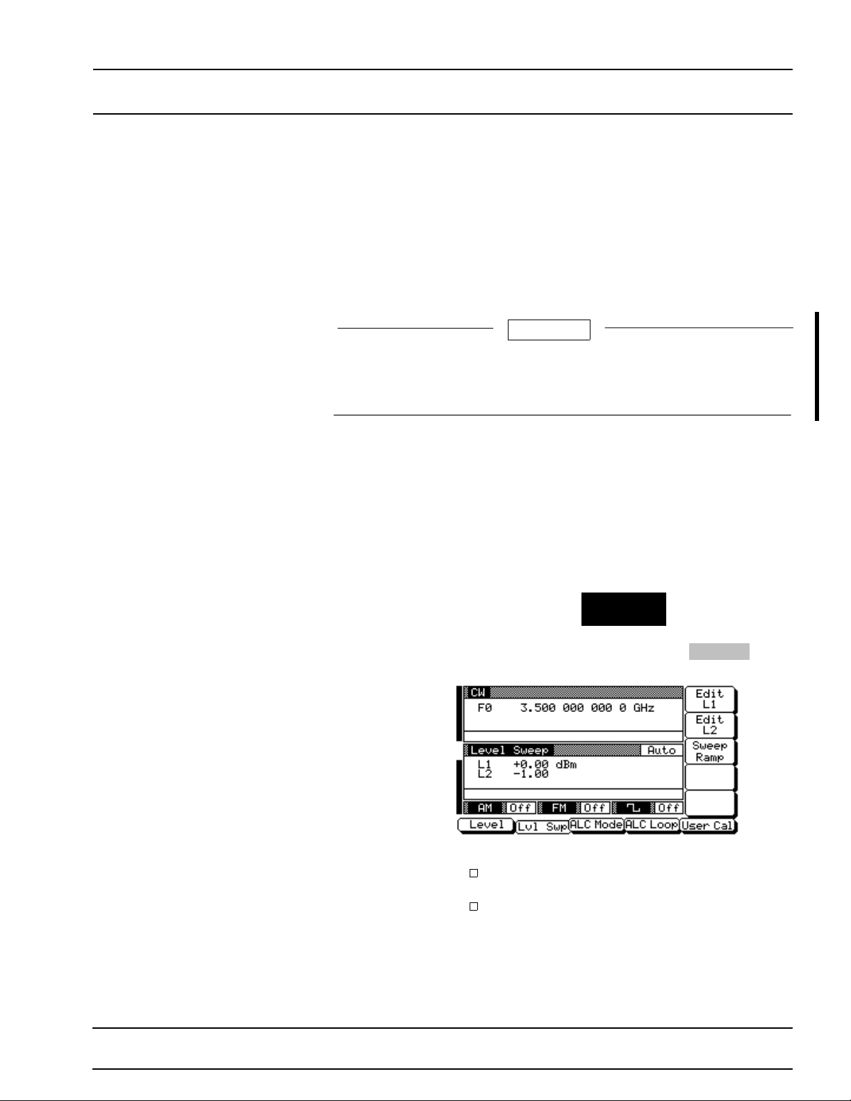
LOCAL (FRONT POWER LEVEL
CAUTION
PANEL) OPERATION SWEEP OPERATION
3-10
POWER LEVEL
SWEEP OPERATION
The sweep gener a tor provides lev eled ou tpu t power swee ps at CW frequencies and in conjun ction with frequency sweeps (analog and step).
Power level swe eps c an be from a high level to a low leve l or vice
versa. The followin g parag raph s prov ide desc ription s an d oper ating instructions for the CW power sweep mode and the sweep frequency/
step power modes. Use the CW Power Sweep Mode and Sweep Fre quency/Step Pow er Mode menu maps (Chapter 4, Fig ures 4-7 and 4-8)
to follow the menu sequenc es.
Performing power level sweeps that cross step attenuator
switch points can cause excessive wear on the switches and
reduce the life expec tanc y of the step attenuator.
Selecting
CW Power
Sweep Mode
In the CW power sweep mode, output power steps
between any two powe r levels at a single CW frequency. Menus provided let you set or selec t the
sweep range, the step size, the dw ell time-per-step,
and the sweep trig g er.
To place the 681XXB in a CW power sweep mode
from a CW frequency menu, press the main menu
key
LEVEL/ALC
SELECT
At the resulting menu display, press
CW Level Sweep Menu (below) is displayed.
This menu lets you perform the following:
Select a power level sweep ran ge (edit the
sweep start and stop power level parameters).
Go to the sweep ramp menu (set the dwell
time-per-step, the step size or number of steps,
and select a sweep trigger).
Lvl Swp . The
681XXB OM 3-41
Changed: November 1995
Page 70
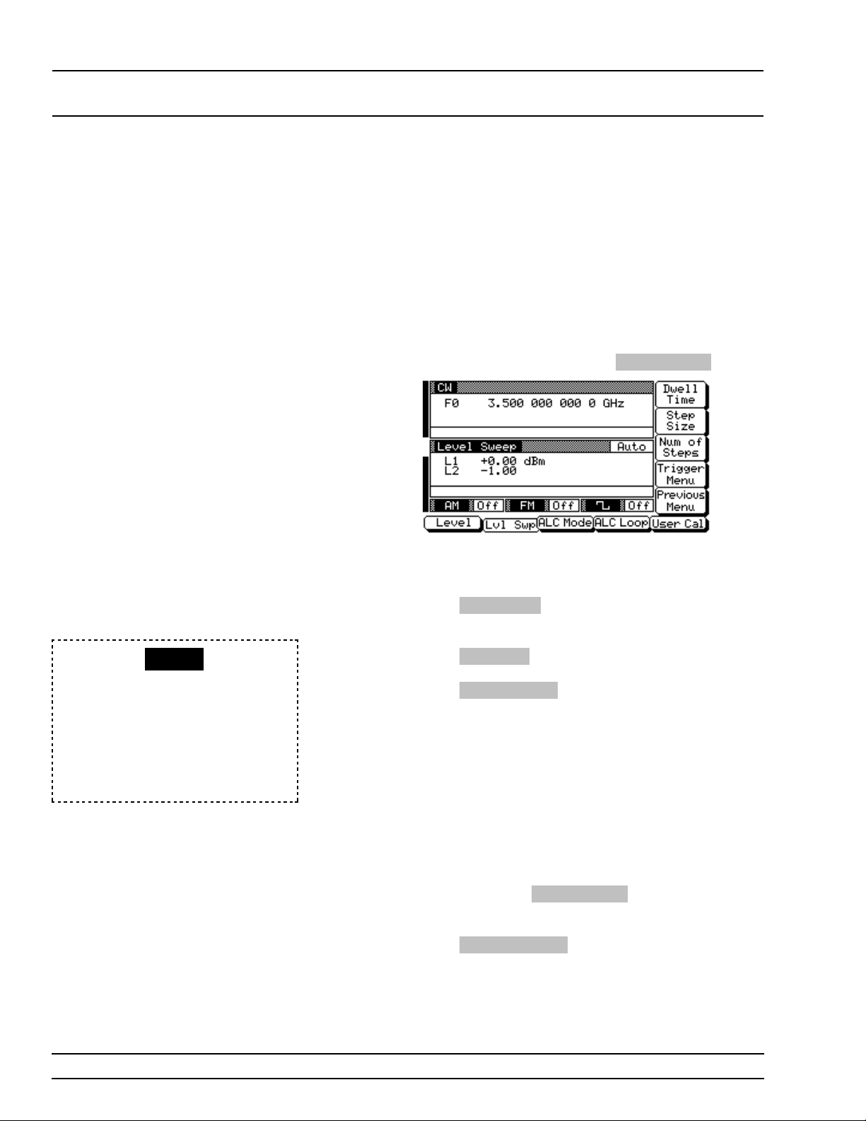
LOCAL (FRONT POWER LEVEL
PANEL) OPERATION SWEEP OPERATION
Setting CW
Power Sw ee p
Step Size
and Dwell
Time
There are two ways to set the size of each step of
the CW power sweep— set the step size or set the
number of steps. The step size range is 0.01 dB to
the full power range of the synth esizer ; the number
of steps range is 1 to 10,000. The dwell time-perstep of the CW power sweep can be set for any time
in the range of 1 ms to 99 sec. The step size and
dwell time-per- step are set from the CW level sweep
ramp menu.
To go to the CW Level Sweep Ramp menu from the
CW Level Sweep men u , pr es s
This menu lets you set the dwell time, the step size,
the number of steps, and go to the trigger men u.
Sweep Ramp .
RANGE
This error message is displayed
when (1) the step size value entered
is greater than the level sweep
range or (2) the number of steps
entered result s in a step size of less
than 0.01 dB. Entering a valid step
size will clear the error.
Press
Dwell Time to open the dwell time-per-step
parameter.
Press
Step Size to open the step size parameter.
Num of Steps to open the number of step s
Press
parameter.
Open the parameter you wi sh to change, then edit
the current value using the cur sor contr ol key or rotary data knob or enter a new value usin g the key
pad and approp riate ter mination key. When you
have finished setting the ope n parameter, close it by
pressing its menu soft-key or by making another
menu selection.
To go to the CW Level Sweep Trigger menu from
this menu, press
lets you select a CW power sweep trigg er.
Press
Previous Menu to return to the CW Level
Sweep menu.
Trigger Menu . The trigger menu
3-42 681XXB OM
Page 71
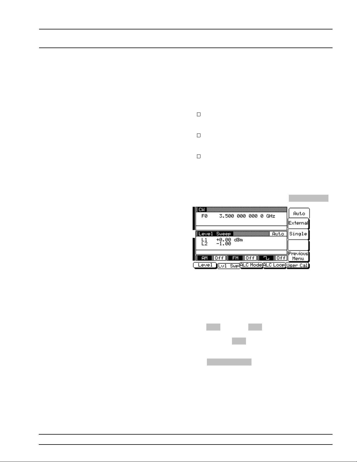
LOCAL (FRONT POWER LEVEL
PANEL) OPERATION SWEEP OPERATION
Selecting a
CW Power
Sweep
Trigger
There are three modes of triggering provided for the
CW power sweep— automatic , exter nal, and sing le.
The sweep trigg er is selec table from the CW Level
Sweep T r ig ger menu . The followin g is a description
of each trigger mode.
Auto (Auto matic)–The CW power sweep continually sweeps from its start power level to
its stop power level with optimal retrace time.
External–Th e CW pow er sweep rec urs wh en
triggered by an extern al TTL-compatible c loc k
pulse to the rear panel AUX I/O connect or.
Singl e –A single CW power sweep starts when
the trigger key is pr es sed. If a sweep is in progress when the key i s pressed, it aborts an d r esets.
To go to the CW Level Sweep Trigger menu from the
CW Level Sweep Ramp men u, press
Trigger Menu .
To select a CW power sweep trigg er mode, press its
menu soft-key. A message showing the CW pow er
sweep trigger mode selec ted appear s on the right
side of the level mode title bar .
If you selec t the sin gle sweep trigger mo de, the
menu display ch ang es, add ing the men u soft-k ey labeled
Tr ig . Pressing Trig starts a single CW
power sweep. If a single CW pow er sweep is in progress, pres sing
reset.
Press
Previous Menu to return to the CW Level
Sweep Ramp menu.
Trig causes the sweep to abort and
681XXB OM 3-43
Page 72
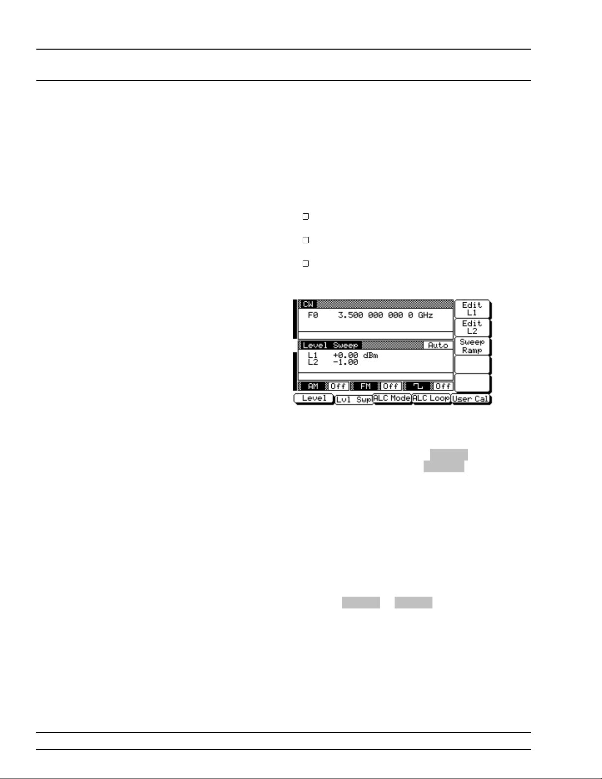
LOCAL (FRONT POWER LEVEL
PANEL) OPERATION SWEEP OPERATION
Selecting a
Power Lev el
Sweep Range
Selecting a power level sweep r ange c onsists of
choosing a start and stop level for the pow er level
sweep. The power level sweep range selection process is identical for all power level swe ep modes—
CW power sweep, analog sweep frequency/step
power, and step sweep fr equ enc y /step pow er. You
can select a power lev el swee p ran ge as follows:
Edit the curren t star t and stop power level parameter values.
Enter new start and stop power level parameter values.
Select one of the preset power level swee p
range parameters ( L1-L2, L3-L4, L5-L6, L7-L8,
or L9-L0).
Editing the Cur re nt Star t / Sto p Po wer Lev el s
To edit the current powe r level swee p rang e, start
by openin g either the start or stop powe r lev el parameter (in the d i splay abov e,
start power level paramete r;
stop power level parameter) .
Edit the open powe r level par ameter using the cursor control key or the rotar y data kn ob. When yo u
are finished, close the open par ameter by pressin g
its menu edit soft-key or by mak ing another menu
selection.
Entering New Start / Stop Power Levels
To enter a new power level sw eep range start by
openin g either the start or stop power level parame ters (press
Enter a new powe r level usin g the keypad an d appropriate terminator key. When you are finished,
close the open parameter by pressing its menu edit
soft-key or by making an othe r menu selection .
Edit L1 or Edit L2 ).
Edit L1 open s th e
Edit L2 opens the
3-44 681XXB OM
Page 73
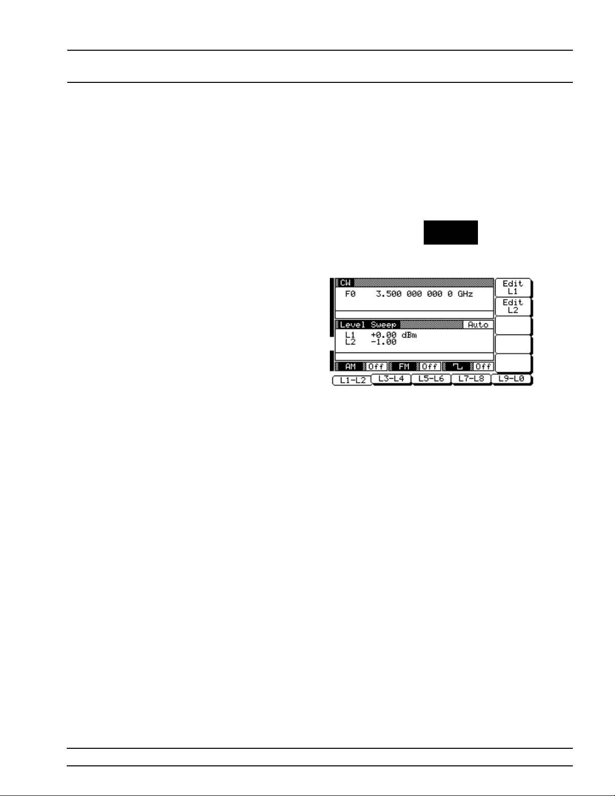
LOCAL (FRONT POWER LEVEL
PANEL) OPERATION SWEEP OPERATION
Selecti ng a Preset Powe r Lev el Swee p Ran ge
There are five preset power level sweep range parameters selectable in the pow er level swe ep modes.
These preset power level sweep r ang e par ameter s
are L1-L2, L3-L4, L5-L6, L7-L8, a nd L9-L0.
To select one of the preset power leve l sweep r ang es
from a Level Sweep menu, press the main menu key
LEVEL
CONTROL
The Level Sweep Con tro l menu (below ) is displayed.
In addition to letting you select one of the pre set
sweep ranges for the power level sweep, this menu
lets you set the start and stop power level parameters for each preset sweep range.
Setting a Pres et Power Level Sweep Range–At
the Level Sweep Contr ol menu, select the power
level sweep range (L1-L2, L3-L4, L5-L6, L7-L8, or
L9-L0) that you wish to set. The menu then displays
the current power level parame te rs for the selec ted
power level sweep range. Now, use the menu ed it
soft-keys to open the power lev el par ameter s for editing.
Edit the current power level parameter values or enter new power lev el p arameter values for the power
level sweep rang e. To close the open power leve l parameter when you are finish ed, pre ss its menu edit
soft-key or make another menu selection.
You can set all the preset power leve l sweep rang e s
in this manner.
681XXB OM 3-45
Page 74
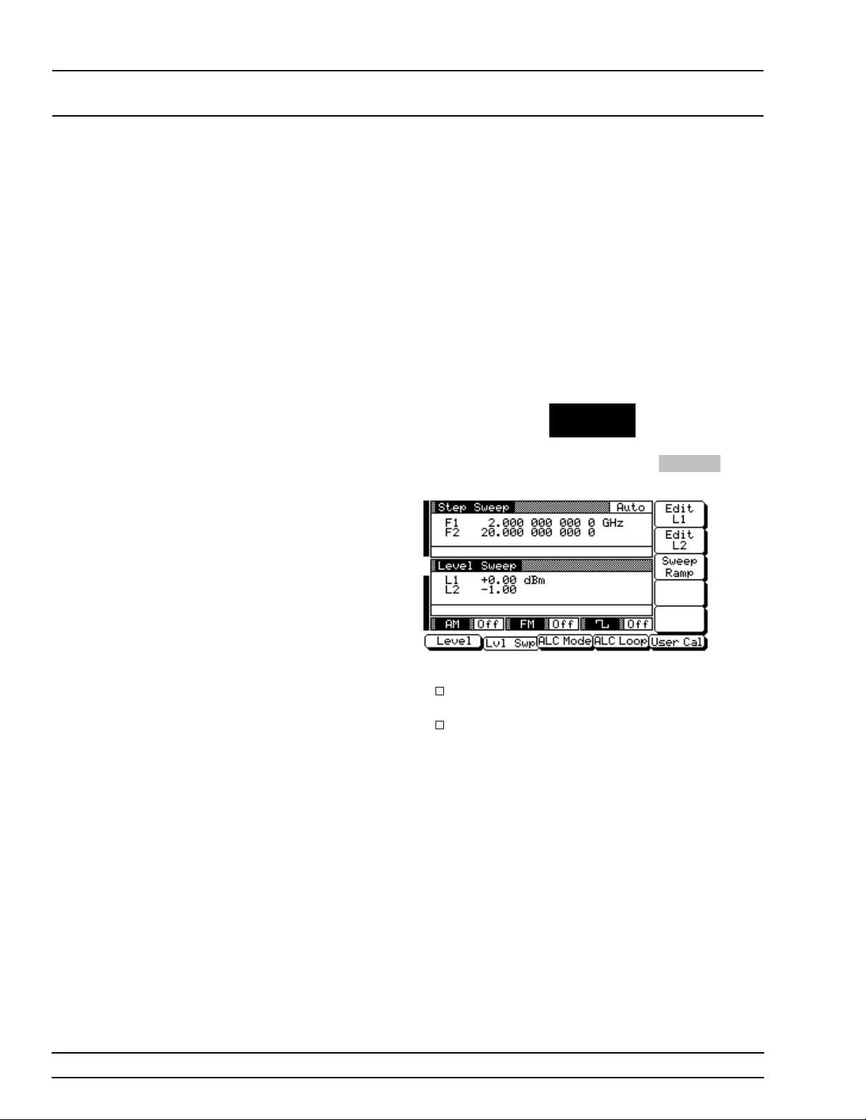
LOCAL (FRONT POWER LEVEL
PANEL) OPERATION SWEEP OPERATION
Selecting a
Sweep Frequency / Step
Power Mo de
In analog sweep fr equ en cy/ s tep power mode or step
sweep frequen c y/step pow er mode, a power leve l
step occurs after each frequen cy sweep. The powe r
level remains constant for the length of time required to complete each frequen cy sweep. Menus
provided let you control the power level sweep
range and step size.
To select an analog swee p fre que ncy /step pow er
mode, start with an analo g sweep men u display; to
select a step sweep frequency /step pow er mode,
start with a step sweep menu display. Then press
the main menu key
LEVEL/ALC
SELECT
At the resulting menu display, press
Level Sweep Menu is displayed.
Lvl Swp . The
This menu lets you perform the following:
Select a power level sweep ran ge (edit the
sweep start and stop power level parameters).
Go to the sweep ramp menu (set the step size
or number of steps).
3-46 681XXB OM
Page 75
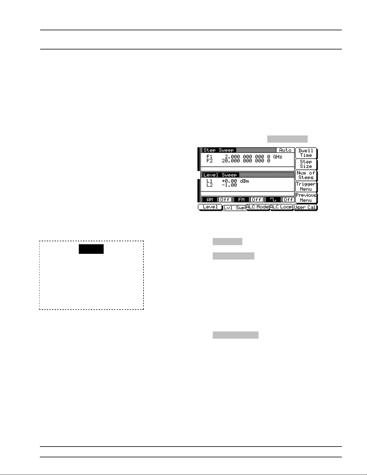
LOCAL (FRONT POWER LEVEL
PANEL) OPERATION SWEEP OPERATION
RANGE
This error message is displayed
when (1) the step size value entered
is greater than the level sweep
range or (2) the number of steps
entered result s in a step size of less
than 0.01 dB. Entering a valid step
size will clear the error.
Setting
Power Lev el
Step Size
There are two ways to set the step size of the power
level step that occur s after each frequency sweep –
set the step size or set the number of steps. The
step size range is 0.01 dB to the full power range of
the synthesizer; the number of steps range is 1 to
10,000. The power level step size is set from the
level sweep ramp menu.
To go to the Level Sweep Ramp menu from the
Level Sweep menu, press
This menu lets you set the step size and the number
of steps.
Press
Step Size to open the step size parameter.
Num of Steps to open the number of step s
Press
parameter.
Open the parameter you wi sh to change, then edit
the current value using the cur sor contr ol key or rotary data knob or enter a new value usin g the keypad and approp riate ter mination key. When you
have finished setting the ope n parameter, close it by
pressing its menu soft-key or by making another
menu selection.
Sweep Ramp .
Press
Previous Menu to return to the Level Sweep
menu.
681XXB OM 3-47
Page 76

LOCAL (FRONT LEVELING
PANEL) OPERATION OPERATIONS
3-11
LEVELING
OPERATIONS
The 681XXB generates leveled output power over a maximum range
of up to 28 dB (up to 131 dB with Option 2). Instruments with Option
15A provide leveled outpu t power ov er a maximum ran g e of up to
22 dB (up to 125 dB with Option 2). An automatic lev el co ntr ol (ALC)
system contro ls the amplitude an d pow er level of the RF output. The
operator can selec t the ALC mode of oper ation —in ter nal, exter nal ( detector or power meter), or fixed gain (ALC off). In addition, the
681XXB provides (1) an ALC pow er slope fu nction that provides c ompensation for high frequ enc y system or cable losses, (2) a decouple
function tha t allows decoup ling of the step attenuator (if equipped)
from the ALC system, and (3) a user level (flatne ss cor re ction ) calibr a tion function that pr ovides for calibrating out path variation s wi th frequency in a test setup.
The following paragraphs provide descriptions and operating instructions for the power leveling modes and functions. Use the Leveling
Modes menu map (Chapter 4, Fig ure 4-9) to follow the menu sequences.
Selecting a
Leveling
Mode
The ALC system is a feedback c ontrol sy s tem, in
which the output powe r is measured a t a detector
and compared w i th the expec ted pow er lev el. If the
output and desir ed pow er levels do not equal, the
ALC adjusts the power outp ut until they do. The
feedback signal can be pr ov ided by either the internal detector or an exter nal detec tor or power meter.
Alternatively, the output power can be set to a fixed
level without usin g the normal feed back (ALC off).
The ALC mode menu lets you make the selection of
a leveling mode.
To go to the ALC Mode menu, first pr es s the main
menu key
LEVEL/ALC
SELECT
At the Level/ALC Select Menu display, press
ALC Mode . The ALC Mode M en u (below ) is displayed.
3-48 681XXB OM
Page 77
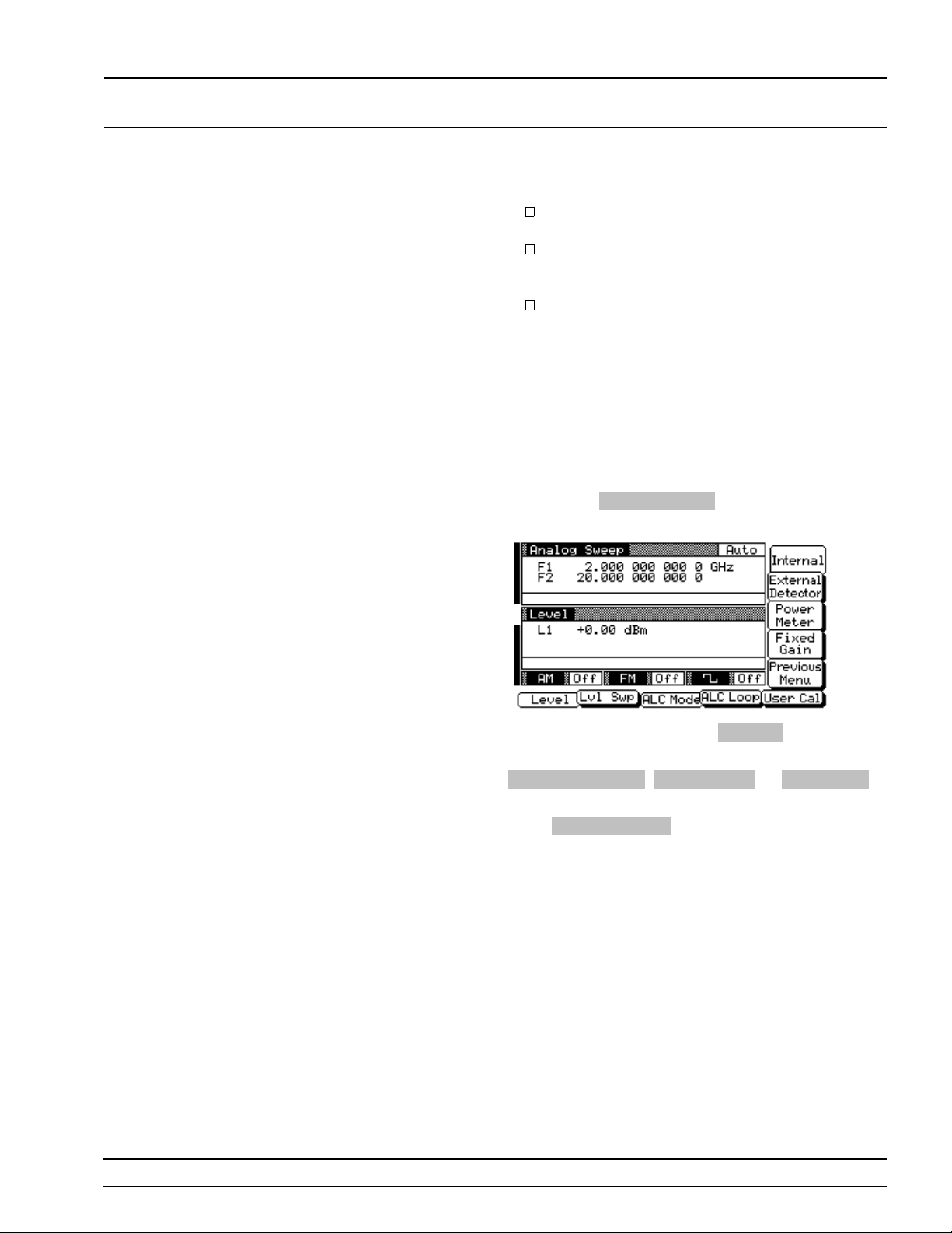
LOCAL (FRONT LEVELING
PANEL) OPERATION OPERATIONS
The ALC Mode men u lets you per form the follow in g :
Go to the leveling men u (selec t the ALC mo de
of operation).
Go to the attenuation menu (dec ou ple the attenuator, if equipped, from the ALC system
and set the power level and attenuation).
Select either the front pane l or rear panel ex ternal ALC input.
Interna l Lev el in g
This is the normal (default) lev elin g mode. Outpu t
power is sensed by the internal detector in the
681XXB. The detector outpu t signal is fed back to
the ALC circuitry to adjust the outpu t pow er lev el.
Internal ALC i s selected f rom the le ve ling menu .
To go to the Leveling M enu from th e ALC M ode
menu, press
(below) is displayed.
Leveling Men u . The Leveling Menu
To select inter nal AL C, press
Pressing one of the other leve ling men u soft-key s
External Detector , Power Meter , or Fixed Gai n
will turn off internal leveling.
Press
Previous Menu to return to the ALC M ode
menu.
Externa l Lev el in g
In external lev elin g, the outpu t pow er fr om the
681XXB is detected by an extern al detector or
power meter. The signal fro m the detec tor or pow er
meter is returned to the AL C c ircu itry. The ALC adjusts the output power to keep the power lev el co nstant at the point of detection. The exter nal AL C
source input is selected from the leveling menu.
Internal .
681XXB OM 3-49
Page 78
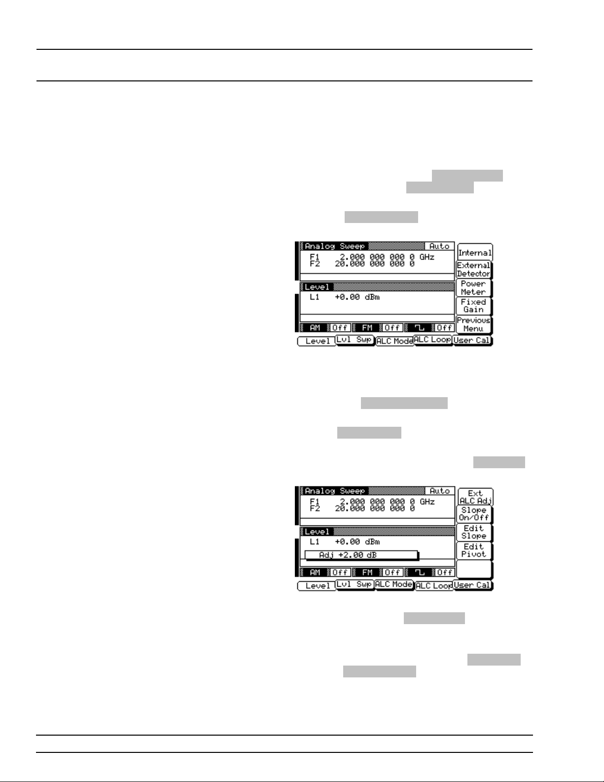
LOCAL (FRONT LEVELING
PANEL) OPERATION OPERATIONS
Before goin g to the Levelin g Men u from the AL C
Mode menu, selec t wh ethe r the exter n al ALC sign a l
is to be connected to the front- or rear - pan el EXT
ALC IN connector.
At the ALC Mode menu , pr es s
lect front panel input, or
rear panel input.
Now, press
Menu.
Next, select the type of external sensor you are using to detect the outp ut pow er.
To select the extern al ALC inpu t from an external
detector, press
To select the extern al ALC inpu t from a power meter, press
After you have made the external AL C inp ut c onn ection and selected the sensor type, press AL C L o op .
The ALC Loop Me nu (be low ) is displayed.
Leveling Men u to go to the Leveling
External Detector .
Power Meter .
Ext ALC Fro nt to se-
Ext ALC Rear to select
While monitor in g the powe r level a t the extern al detection point, first press
cursor control ke y or rotar y data knob to adjus t the
external ALC sig n al to ob tain the set power level.
To return to the Leveling Me nu, press
then press
Leveling Menu .
Ext ALC Adj , then use the
ALC Mode
3-50 681XXB OM
Page 79
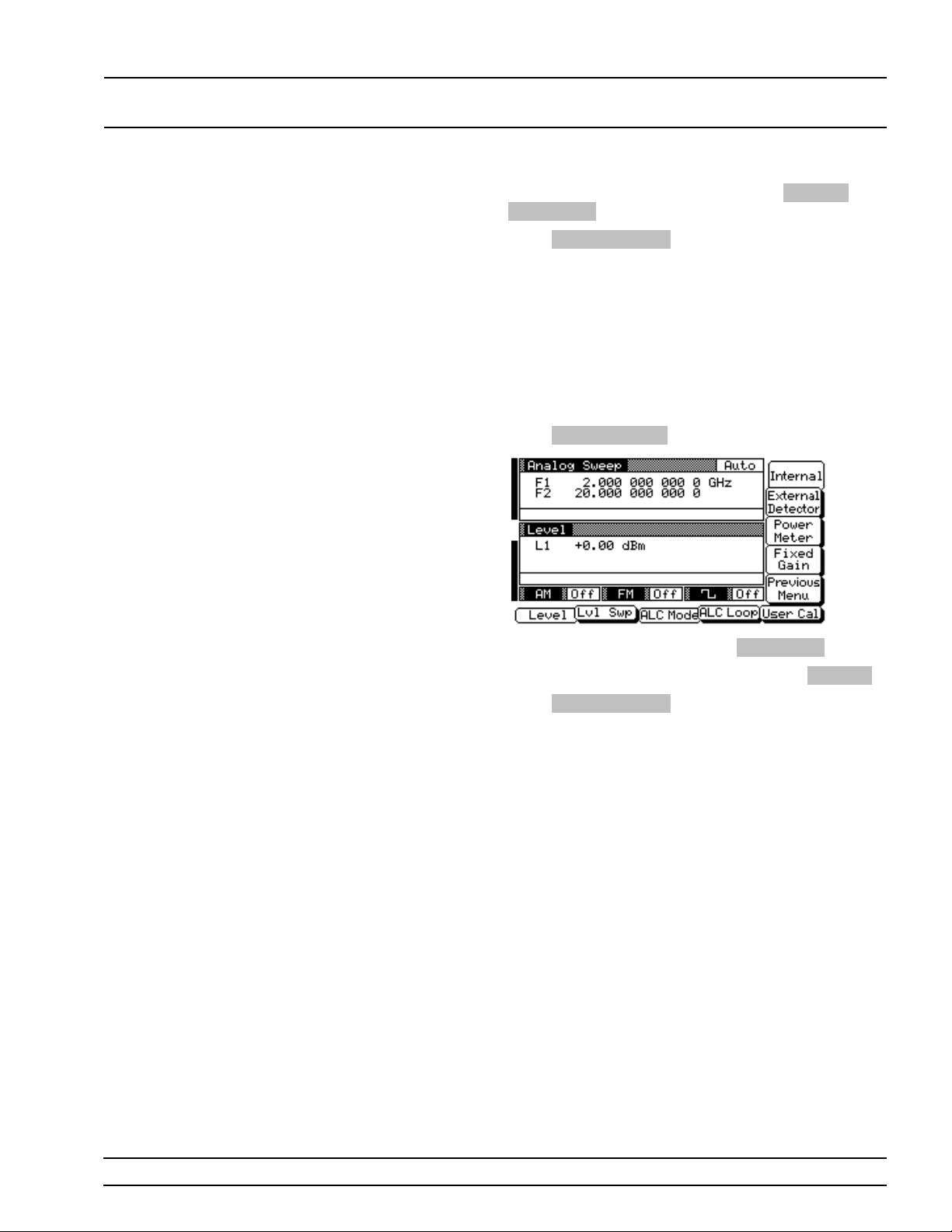
LOCAL (FRONT LEVELING
PANEL) OPERATION OPERATIONS
At the Leveling menu, pressing either Internal or
Fixed Gain will turn off external leveling.
Previous Menu to return to the ALC M ode
Press
menu.
Fixed Gai n
In the fixed gain mod e, the ALC is disabled. The RF
Level DAC and step attenuator (if ins talled) are
used to control the re l ative pow er lev el. Pow er is
not detected at any point, an d the ab solute pow er
level is uncalibrated. Fix ed gain mode is selected
from the leveling menu.
Press
Leveling Menu to go to the Levelin g menu.
To select fixed gain mode, press
To return to normal A L C oper ation , pre ss
Previous Menu to return to the ALC M ode
Press
menu.
Fixed Gain .
Internal .
681XXB OM 3-51
Page 80
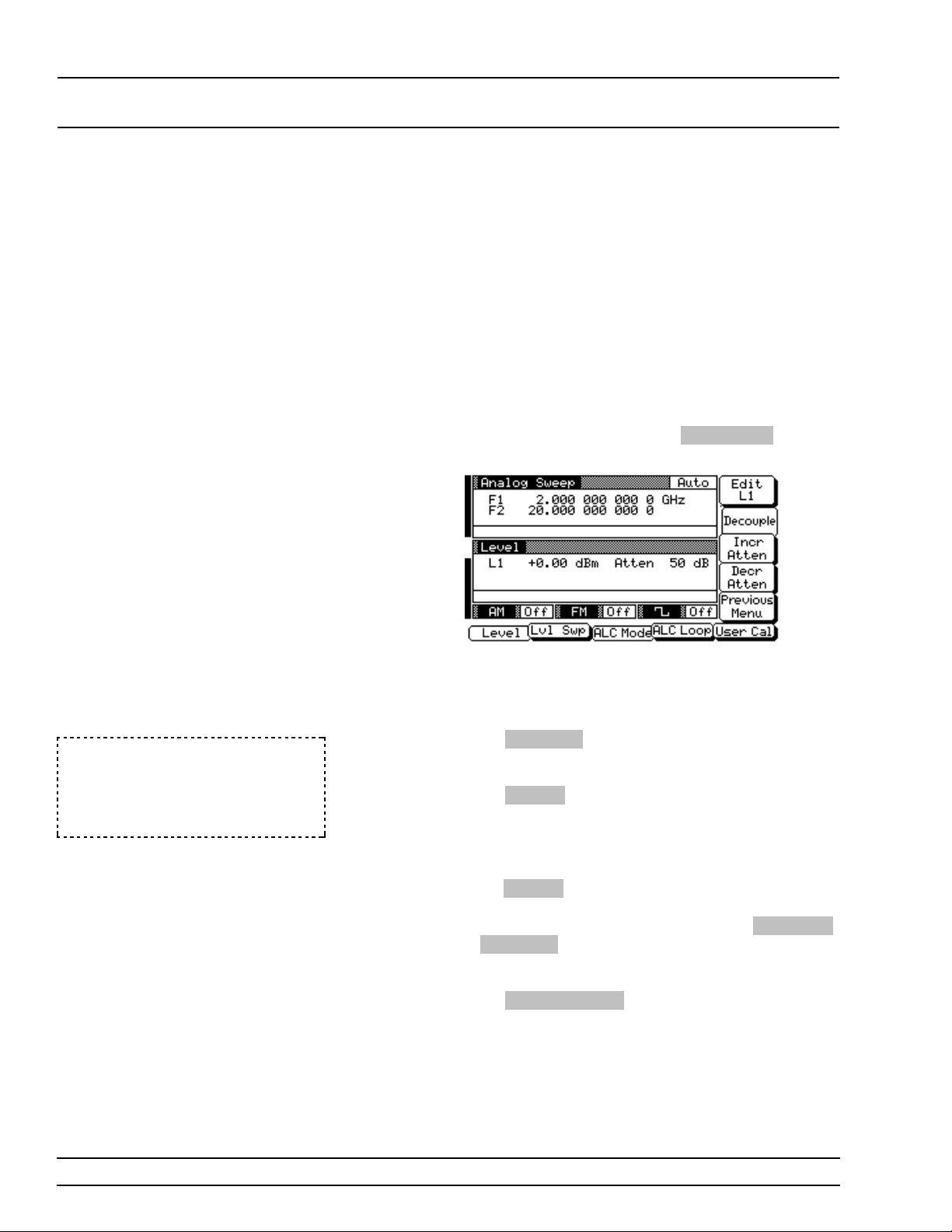
LOCAL (FRONT LEVELING
PANEL) OPERATION OPERATIONS
Attenuator
Decoupling
In 681XXBs equipped with option 2 step attenuators, the ALC and attenuator work in co njunction
to provide leveled output powe r down to –120 dBm.
In the normal (coup led) lev elin g mode, whe n the desired power lev el is set, the correct combin ation of
ALC level and attenua tor setting is determined by
the instrument fir mwar e. In some application s,
such as receiver sensitivity testing, it is desireable
to control the ALC level and attenuator setting separately by decoupling the step attenuator from the
ALC. The ALC mode menu lets you select attenuator decoupling.
At the ALC Mode menu , pr es s
tenuator Menu (below) is displayed.
Atten Men u . Th e At -
NOTE
The set power level may not be
maintained when switching between attenu ator cou plin g mod es.
This menu lets you decou ple the step attenu a tor
from the ALC, set the power leve l, and set the a ttenuation in 10 dB steps.
Press
Decouple to decou ple the s tep attenua tor
from the ALC.
Press
Edit L1 to open the power lev el parame ter
for editing . Edit the curr ent level usin g the cur sor
control key o r rotary data knob or enter a new value
using the key pad and appropr iate te rmin ation key.
When you have finished setting the power level,
press
Edit L1 to close the open parameter.
To change the attenuation setting, press
or
Decr Attn . Pressin g these soft-key s chang es the
attenuation in 10 dB steps.
Press
Previous Menu to return to the ALC M ode
menu.
Incr Atten
3-52 681XXB OM
Page 81
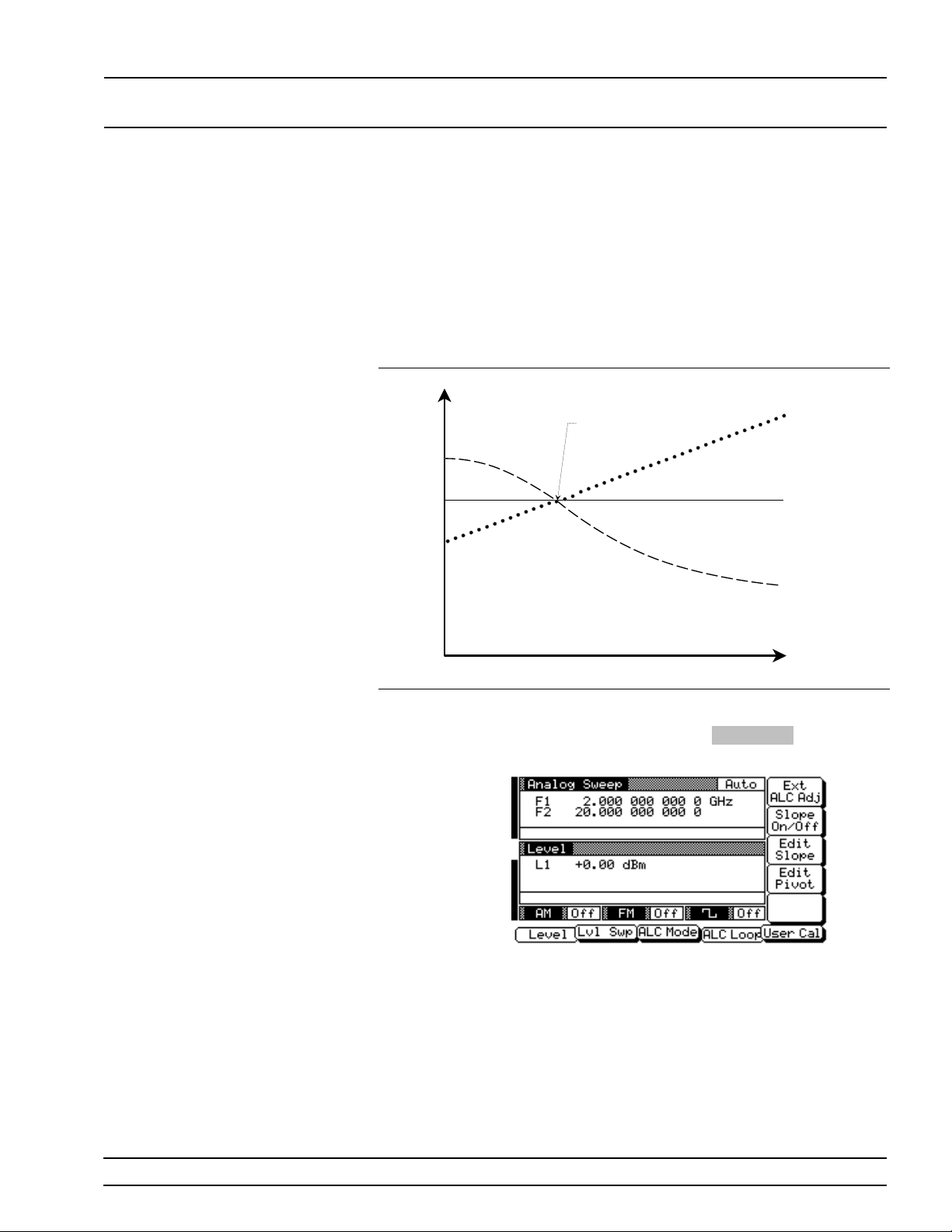
LOCAL (FRONT LEVELING
PANEL) OPERATION OPERATIONS
ALC Power
Slope
Power Level
The ALC power slope function lets you compensate
for system, cable, and waveguide variations due to
changes in frequency, by linearly increasing or decreasing power ou tput a s the frequenc y increa ses.
As shown in the following illustration , the power
slope function provide s you with the ability to set
both the power slope and the piv ot poin t. Th e AL C
loop menu lets you activ ate the ALC p ower slope
function.
Power
Slope
Power Slope
Pivot Point
Power at DUT
With Compensation
Power at DUT
Without Compensation
Frequency
To go to the ALC Loop Menu from th e Le vel/ALC
Control Menu display, press
ALC Loop . Th e AL C
Loop Menu (below) is displaye d.
This menu lets you turn the powe r slope on or off
and edit the slope value and piv ot point fr equ en cy.
681XXB OM 3-53
Page 82
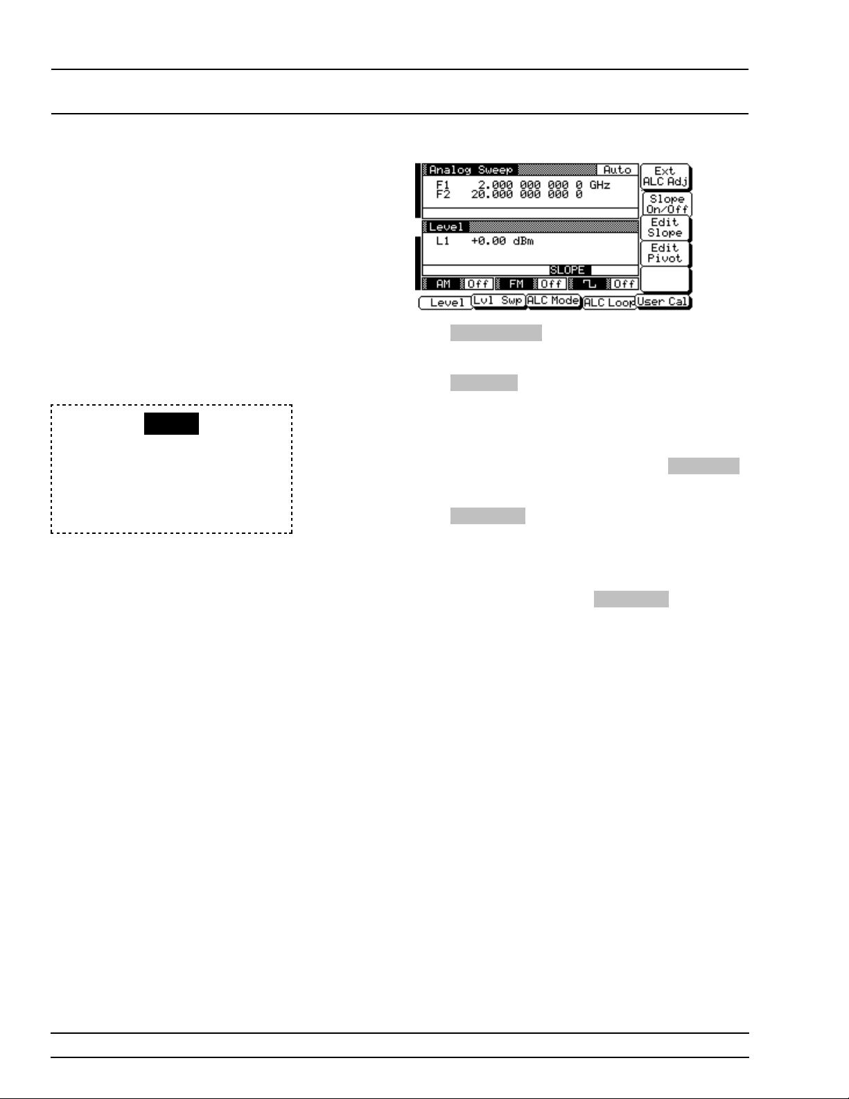
LOCAL (FRONT LEVELING
PANEL) OPERATION OPERATIONS
Press Slope On/Off to activate the ALC power
slope function.
Press
Edit Piv ot to open the pivot point frequency
parameter for editing. Edit the current frequency us-
SLOPE
When Power Slope is selected ON,
this status message is displayed on
all menu displays to remin d the operator that a power slope cor rec tion
has been applied to th e ALC.
ing the cursor control key or rotary data knob or enter a new value using the keypad and appropriate
termination key. When you have finish ed settin g
the open parameter, close it by pressin g
again or by mak ing ano ther menu selection.
Press
Edit Slope to open the slope parameter for
editing. Edit the curren t slope valu e using the cursor control key or rotar y data knob or enter a new
value using the key pad and the STEPS termination
key. Whe n you have finish ed setting the open parameter, close it by pressing
making anothe r men u selection .
Edit Slope again or by
Edit Pi vo t
While monitor in g the powe r level a t the device-under-te st (DUT), adjus t the powe r slope and pivo t
point to level the power at the DUT.
3-54 681XXB OM
Page 83
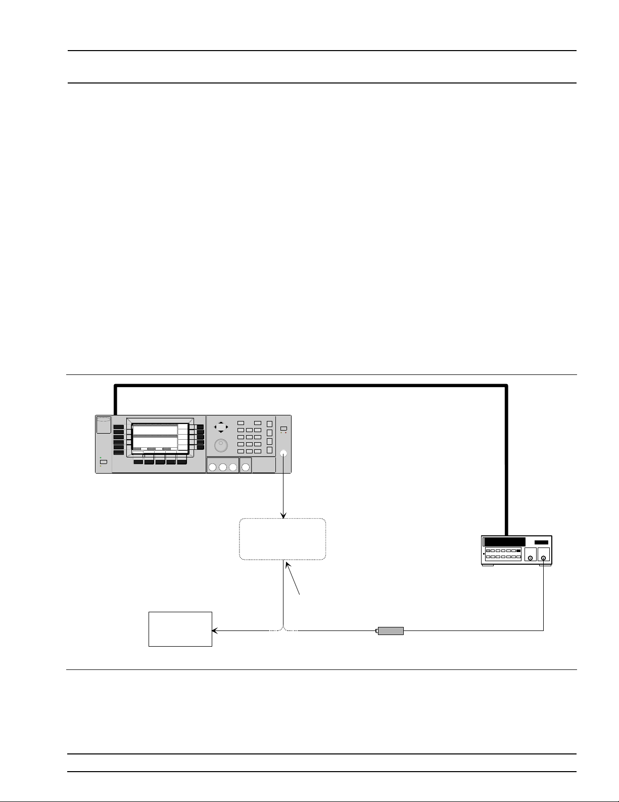
LOCAL (FRONT LEVELING
PANEL) OPERATION OPERATIONS
GPIB
User Cal
(User Level
Flatness
Correction)
681XXB SWEEP GENERATOR
The User Cal (user level flatn es s correction ) fu nction lets you calibrate out path variation s w ith frequency that are cau sed by exter nal switc h ing ,
amplifiers, co up ler s, and cables in the test setup.
This is done by means of an ente red p ower - offset table from a GPIB power meter or calculated data.
When user level flatne ss corr ection is activated, the
set power level is deliver ed at the point in the test
setup where the calibra tion was performe d. Thi s
“flattening” of the test point power level is accomplished by summin g a power- offset wo rd (from the
power- offset table) with the sweep gener ator’s normal power lev el DAC wo rd at each fr equ ency point.
Up to five user level flatness corr ectio n power-offset
tables from 2 to 801 frequency points/table can be
created and stored in 681XX B memory for recall.
The GPIB power meters supported are the Anr i tsu
Model ML4803A and the Hewlett-Packard Models
437B, 438A, and 70100A.
RF
OUTPUT
INPUT
SWITCH MATRIX,
AMPLIFIERS,
COUPLERS, ETC.
FLATNESS
CORRECTED
OUTPUT
DEVICE
UNDER
TEST
Figure 3-4. Setup for Creating a Pow er -Offs et Table (Use r Level Fla tnes s Corre ctio n)
POWER
SENSOR
GPIB
POWER
METER
681XXB OM 3-55
Page 84
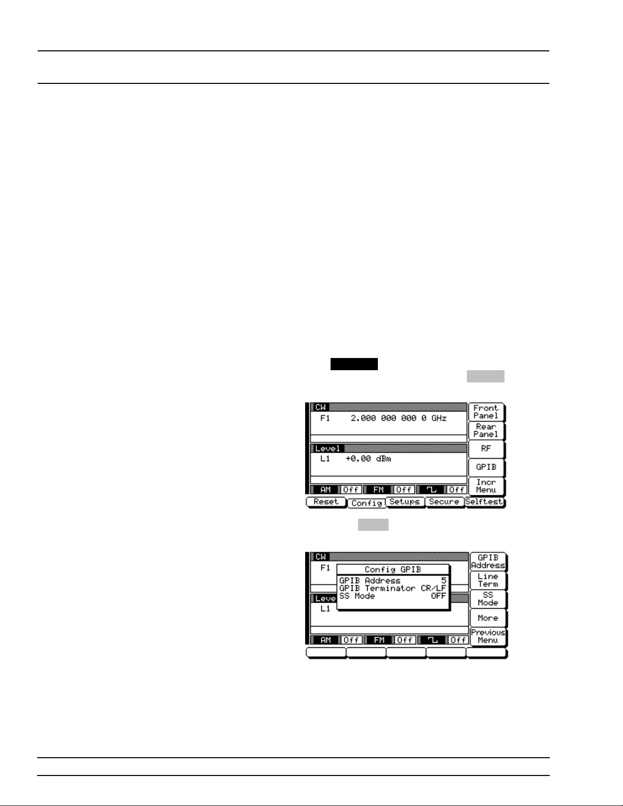
LOCAL (FRONT LEVELING
PANEL) OPERATION OPERATIONS
Equipment Setup
To create a power -off se t table for user level flatn ess
correction , connec t the equ ipmen t (show n in Figur e
3-4) as follows:
Step 1 Using a GPIB cable, conne ct the Pow er
Meter to the 681XXB.
Step 2 Calibrate the Power Meter with the
Power Sensor.
Step 3 Connect the Powe r Senso r to the point in
the test setup where the corrected power
level is desired.
Power Meter Model and G PI B A ddr ess
In order for the 681XXB to contro l the pow er meter,
the GPIB addres s and power meter model must be
selected from the Configure GPIB menu.
Press
SYSTEM to go to the System Menu display.
At the System Menu display, press
System Configuration Menu (below) is displayed.
Next, press
low) is displayed.
GPIB . The Config ure GPIB men u (be-
Config . The
3-56 681XXB OM
Page 85
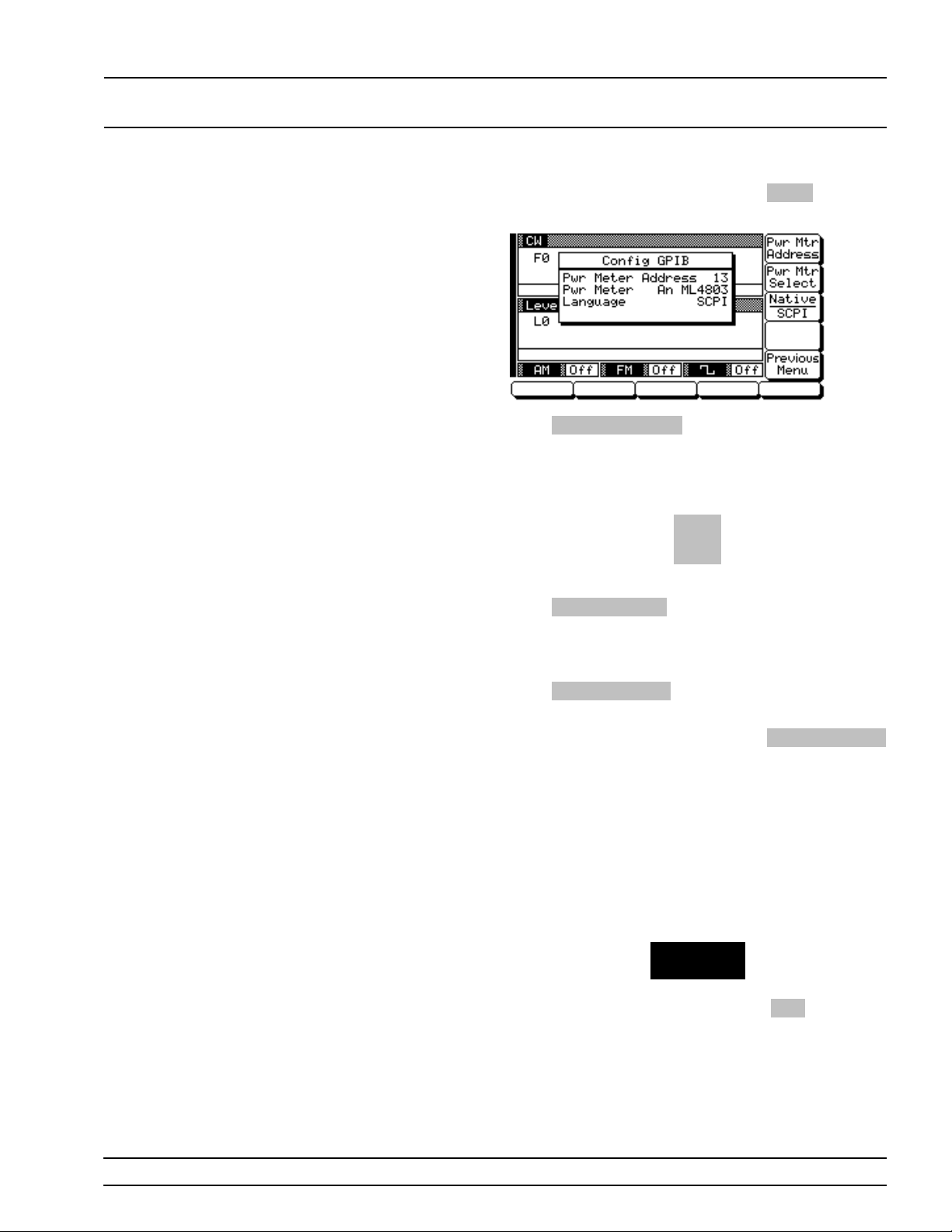
LOCAL (FRONT LEVELING
PANEL) OPERATION OPERATIONS
At the Configure GPIB menu , pres s More to go to
an additional Configure GPIB menu (below).
Press
Pwr Mtr Address to change the address of
the power mete r on the GPIB (the pow er meter’s default address is 13). Enter the new addre ss, between 1 and 30, usin g the cu rso r con trol ke y or the
data entry key pad and the terminator key
Hz
ns
ADRS
The new GPIB address will appear on the display.
Pwr Mtr Select to select the power meter
Press
model being used. (Su ppor ted pow er meter s are the
Anritsu ML4803A and Hewlett-Packard 437B,
438A, and 70100A.)
Press
Previous Menu to return to the main Configure GPIB menu display.
At the Configure GPIB menu , pres s
to return to the System Config u ration men u display.
Creating a Power-Offset Table
The 681XXB mus t be in CW frequency mode an d
fixed (no n-sw ep t) powe r lev el mode in orde r to create a power-offset table for user level flatne ss correction.
Place the sweep generator in CW frequency mode
by pressing the main menu key
CW/SW EEP
SELECT
At the resulting menu display, press
681XXB is now in CW frequenc y mode.
Previous Menu
CW . The
681XXB OM 3-57
Page 86
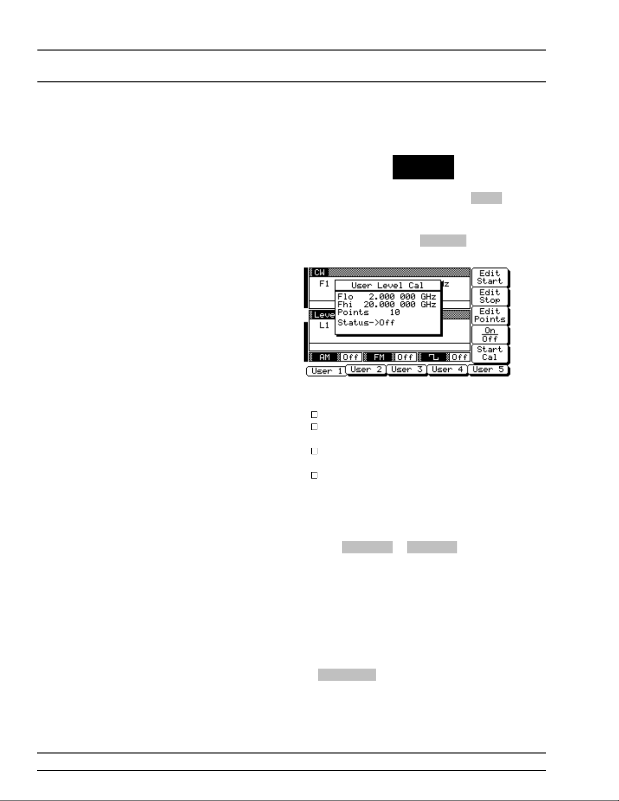
LOCAL (FRONT LEVELING
PANEL) OPERATION OPERATIONS
Place the sweep generator in a fixed power level
mode by pressing the main menu key
LEVEL/ALC
SELECT
At the resulting menu display, press
681XXB is now in fixed (non-sw ept) pow er level
mode.
At the Level Menu, press
Cal menu (below) is displayed.
This menu lets you perform the following:
Create a power- offset table.
Select a measurement frequ enc y range (edit
the start and stop frequency parame ters).
Select the number of points at which cor re ction information is to be taken.
Apply a power-offset table to the test setup.
User Cal . The User Level
Level . The
First, press the menu soft-ke y to select the poweroffset table (User 1, User 2, User 3, User 4, or User
5) that you wish to create.
Next, set the measurement fr equ ency ran g e by
pressing
(Flo) or stop (Fhi) frequency parameter for editing.
Edit the current frequency using the cursor control
key or rotary data k no b or en te r a new value using
the keypad and appropr iate te rmin ation key. When
you have finishe d setting the open parameter, close
it by pressing its menu edit soft-key ag ain or by
making anothe r men u selection .
Then, select the numbe r of frequ en cy points at
which corre ction inf orm ation is to be taken by pressing
rameter for editing . Edit the curr ent nu mber - ofpoints using the cursor con trol ke y or rotary data
knob or enter a new value using the keyp ad and the
Edit Start or Edit Stop to open the star t
Edit Points to open the number-of-points pa-
3-58 681XXB OM
Page 87
LOCAL (FRONT LEVELING
PANEL) OPERATION OPERATIONS
STEPS termination key. (The number of points
range is 2 to 801.) When you have finishe d setting
the open number -of -poin ts par ameter, close it by
pressing
menu selection.
Edit Po in t s again or by making another
USER 1...5
When a power-offset table is selected ON, this status message is
displayed on all menu displays to
remind the oper ator that user lev el
flatness correction has been applied
to the ALC.
Now, press
power level cor re ction inf orm ation at each fre quency point. Durin g this process the men u displays the status: Ca librating along with the current
measurement frequency point.
Once the power-offset table has been created, it is
stored in non-volatile memory. The power-offset table is now ready to be applied to the test setup. Disconnect the Power Sensor and Power Meter from
the te st setup.
Applying User Level Flatness Correction
Whenever use r level flatness corr ection is applied to
the test setup by activating the power- offset table,
the set power level is deliv ered at the poin t whe re
the calibration was per for med.
To activate the selected pow er-offset table and apply
user level flatness cor rec tion to the test setup, pre ss
On/Off . The User Level Cal menu will display the
status: On.
To turn off the selected pow er-offset table and remove user lev el flatness correction fr om th e te st
setup, press
menu will display the status: Off.
Start Cal to begin automa tically taking
NOTE
To terminate the measureme nt pr oce ss at
any time before completion, press
On/Off again . The User Lev el C al
Abort .
Entering a Power-Offset Table via GPIB
User level flatness correction can be applied to the
test setup using a power-offset table created from
calcula ted data and enter ed via the GPIB. Refe r to
the 681XXB Programmin g Manual (P /N 10370-
10260) for information and instructions on creating
a power-of fset table and enter in g it via the GPIB.
681XXB OM 3-59
Page 88

LOCAL (FRONT LEVELING
PANEL) OPERATION OPERATIONS
Erasing th e Power -O f fset Tables from Memo ry
The power-o ffset tables are stored in non -volatile
memory. A master reset is required to erase the contents of the tables and reprogram them with default
data.
To perform a master reset, procee d as follows:
NOTE
The master reset function overwrites all information stored in the
non-volatile memory with default
values. This includes the nine
stored front panel setups.
Step 1 With the 681XXB in standby, press and
hold the RF OUTPUT ON/OFF ke y.
Step 2 Press the LINE OP ERATE/STANDBY ke y
to turn the instrument on.
Step 3 When the first menu is displayed (afte r
the start-up display), release the RF OUT-
PUT ON/OFF key.
The contents of non- vo latile memory have now been
erased and reprogrammed with default data.
3-60 681XXB OM
Page 89
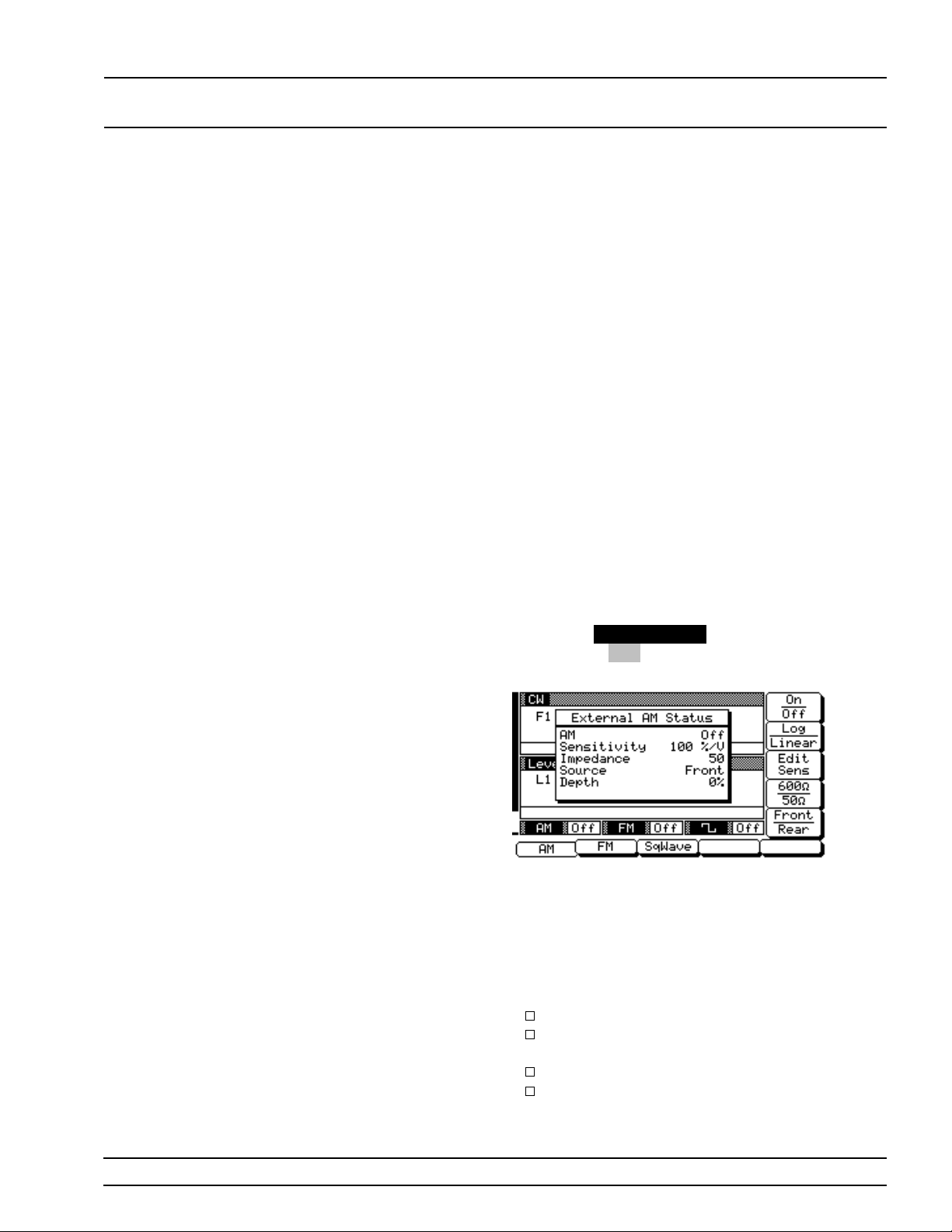
LOCAL (FRONT SIGNAL
PANEL) OPERATION MODULATION
3-12
SIGNAL MODUL ATI ON
The sweep gener ator prov ides AM, FM, and square wave modulation
of the output signal. All modu lation modes—AM , FM, an d squar e
wave—can be activ e simultane ou sly. The following paragrap hs prov ide
description s and ope ratin g ins tructio ns for each modulation mode.
Use the Amplitude Modulation Mod e, Freque ncy Modu lation Mode,
and Square Wave Modulation Mo de men u maps (Chapte r 4, Figure s
4-10, 4-11, and 4-12) to follow the menu sequen c es.
Amplitude
Modulation
Operat ing
Modes
Providing
Amplitude
Modulation
The sweep gener ator has two AM operation modes—
Linear AM and Log AM. In Linear AM mode, sensitivity is continuously variable from 0 %/V to
100%/V. The amplitude of the RF output changes
linearly a s the ex ternal AM inpu t c han g es.
In Log AM mode, sen sitivity is c ontinu ou sly var iable from 0 dB/V to 25 dB/V. The ampli tude of the
RF output chan ges e xpon en tially as the AM inpu t
changes.
To provide amplitude modu lation , fir st set up the external signal generator, then connect it to either the
681XXB front or rear panel AM IN connector.
Next, press
display, press
(below) is displayed.
MODULATION . At the resu lting me nu
AM . The Ex ter nal AM Status Menu
This menu contains an external AM status window
that shows the current menu selections and the
measured AM De pth. (The AM depth measuremen t
function measu res the voltag e of the external modu lation signal and calcu lates the per cen tage modu lation value.) Th i s menu lets you perform the
followin g:
Turn AM on and off.
Select the Linear AM or Log AM oper atin g
mode.
Set the AM Sensitivity
Select the input impedance (600Ω or 50Ω ) of
the input con ne ctor.
681XXB OM 3-61
Page 90
LOCAL (FRONT SIGNAL
PANEL) OPERATION MODULATION
Select the input con ne ctor (fron t panel or rear
panel AM IN) that is connected to the external
signal source.
Press
On / Off to turn AM on and off. Both the AM
status display and AM modulation status ar ea w ill
reflect you r selec tion.
Press
Log / Linear to select the AM operating
mode. The AM status d isplay w ill r eflec t you r selec-
ERR
tion as XX dB/V (Log) or XX %/V (Linear ).
This error message is displayed
when the external AM modulating
signal exceeds the input voltage
range. The message “Reduce AM
Input Level” also appears at the bottom of the AM status display. AM is
turned off until the modulatin g signal is within the input voltage
range.
NOTE
Refer to Appendix B, page B-5, for
the maximum FM deviation specifications for 681X5B models.
Frequency
Modulation
Operat ing
Modes
Press
Edit Sens to open the AM Sensitivity parameter, then edit the current valu e using the cursor control key or rotar y data knob or enter a new
value using the keypad an d the appr opr iate terminator key (kHz/µs/STEPS for Linear; MHz/ms/dB for
Log). The AM Sensitivi ty range is 0 %/V to 100 %/V
in Linear and 0 dB/V to 25 dB/V in Log. To close the
open Am Sensitiv ity p arame ter, pr es s
make another menu selection .
Press
600Ω / 50Ω to select the input impedance of
the input con n ec to r. The AM status display will reflect your selec tion.
Press
Front / Rear to select the front panel or rear
panel AM IN connector. The AM status display will
reflect you r selec tion.
The sweep gener a tor has two FM operation modes—
Locked FM and Unlocked FM. In Locked FM mode,
frequenc y modu l ation of the outpu t signal is acco mplished by summin g the modulatin g signal in to the
FM control path of the YIG ph ase-loc k loop. Maximum FM deviation i s the lesser of ±10 MHz or
Fmod x 300 for 1 kHz to 500 kHz rates.
In Unlocked FM mode, the YI G phase-lo ck loop i s
disabled to allow for peak FM deviation s of up to
100 MHz. There are two Unlock ed FM modes—Unlocked Narro w an d Unloc k ed Wide.
Edit Sens or
In Unlocked Narr ow mode, frequ en c y modulation is
obtained by apply ing the modu latin g signal to the
fine tuning coil of the YIG-tu ned osc illator. Unlocked Narro w FM mode allow s maximum dev i ations of ±10 MHz for DC to 500 kHz rates.
3-62 681XXB OM
Page 91
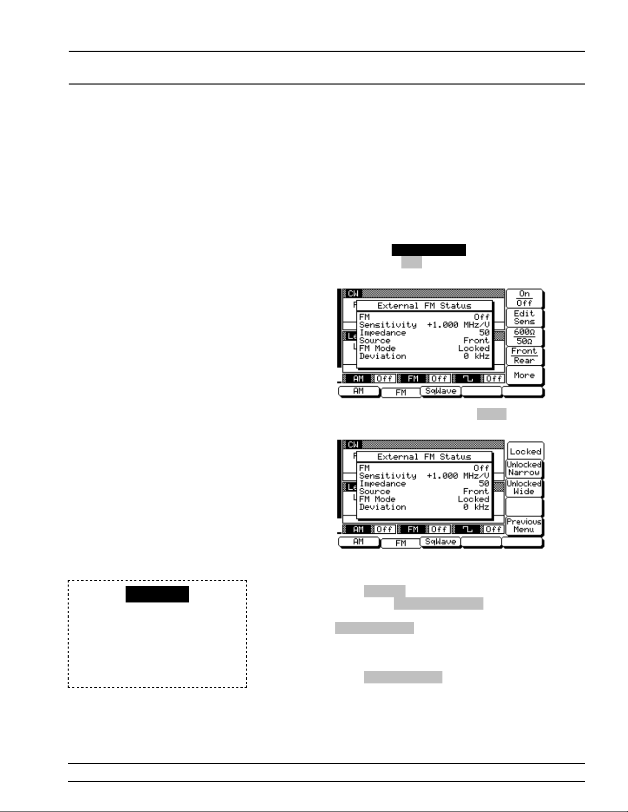
LOCAL (FRONT SIGNAL
PANEL) OPERATION MODULATION
In Unlocked W ide mode, frequ en cy modu lation is accomplished by apply ing the modulatin g sign al to
the main tuning co il of the YIG-tu ne d oscillator. Unlocked W ide FM mode allow s maximum dev iation s
of ±100 MHz for DC to 100 Hz rates.
Providing
Frequency
Modulation
To provide frequ en cy modulation, first set up the external signal generator, then connect it to either the
681XXB front or rear panel FM IN connector.
Next, press
display, press
(below) is displayed.
Now, press the menu soft-ke y
External FM Status Menu (below) is displayed.
MODULATION . At the resu lting me nu
FM . The External FM Status Menu
More . The additional
This menu lets you select the FM oper ating mode.
Press
UNLOCKED
When Unlocked Narrow FM or Unlocked W ide FM is sele cted ON, this
warning message is displayed on a ll
menu displays to remind the oper ator that the c arrier frequenc y is not
phase-locked.
Locked to select the Locked FM operating
mode; press
locked Narro w FM oper ating mode; or pres s
Unlocked Wide to select the Unloc k ed Wide FM
operating mode. The FM status display will reflect
your selection.
Press
nal FM Status Menu display (next page) .
Unlocked Narrow to select the Un-
Previous Menu to return to the main Exter-
681XXB OM 3-63
Page 92
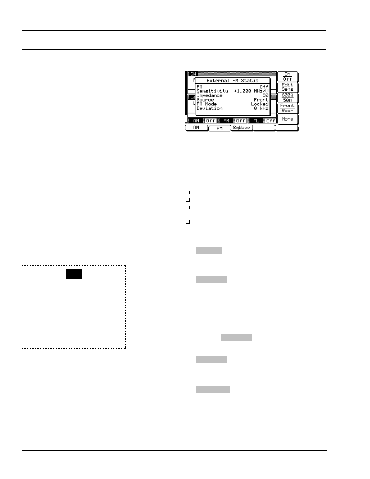
LOCAL (FRONT SIGNAL
PANEL) OPERATION MODULATION
This menu contains an extern al FM status window
that shows the current menu selections and the
measured FM Deviation. (The FM deviation measurement func tion measur es the voltage of the exter nal modulation signal an d calc ul ates the peak
frequency deviation.) This menu lets you perform
the following :
Turn FM on/off.
Set the FM sensitivity.
Select the input impedance (600Ω or 50Ω ) of
the input con ne ctor.
Select the input con ne ctor (fron t panel or rear
panel FM IN) that is connected to the external
signal source.
ERR
This error message is displayed
when the external FM modulating
signal exceeds the input voltage
range. The message “Reduce FM
Input Leve l” also appear s at the bottom of the FM s tatus display. FM is
turned off until the modu lating signal is within the input voltage
range.
Press
On / Off to turn FM on and off. Both the FM
status display and FM modulation status area will
reflect you r selec tion.
Press
Edit Sens to open the FM Sensitivity parameter, then edit the current valu e using the cursor control key or rotar y data knob or enter a new
value using the keypad an d the appr opr iate terminator key. The FM Sensitivity range is ±1 kH z/V to
±20 MHz/V for Locked and Unlocked Narrow FM
modes and ±100 kHz/V to ±100 MHz/V for Unlocked
Wid e FM mode. To close the open FM Sensitivity parameter, press
lection.
Press
600Ω/50Ω to select the input impedance of
the input connec tor. The FM status display will reflect your selec tion.
Press
Front/Rear to selec t th e fr on t or rear pan el
FM IN connector. The FM status display will reflect
your selection.
Edit Sens or make another menu se-
3-64 681XXB OM
Page 93
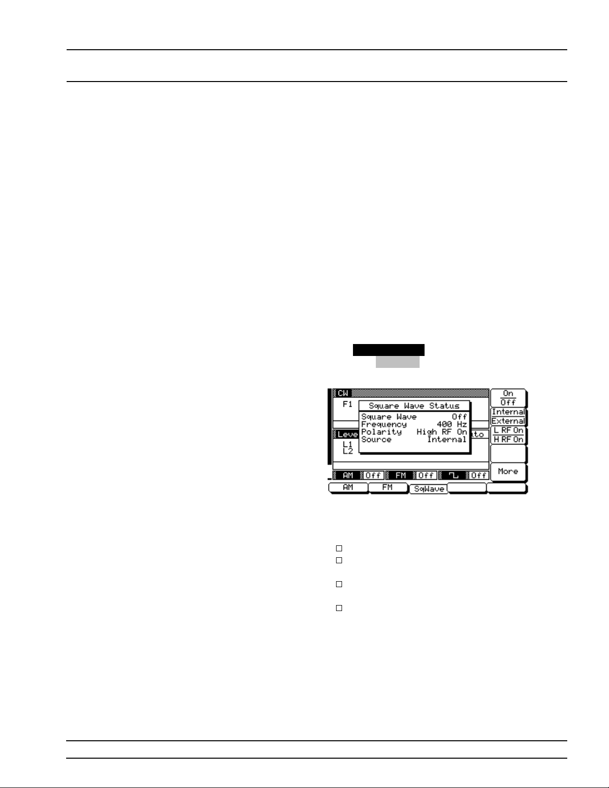
LOCAL (FRONT SIGNAL
PANEL) OPERATION MODULATION
Square Wave
Modulation
Operat ing
Modes
Providing
Square Wave
Modulation
The 681XXB provides square wave (pulse) modulation of the output signal using modulatin g signals
from either its internal square wave generator or an
external signal generator.
The sweep generator’s internal square wave generator outputs modu l a ting sig n a l s of 400 Hz, 1 kHz,
7.8125 kHz, and 27.8 kHz. Th e modulating sign al s
are selectable from a menu.
The 681XXB accepts modulating signals from an external signal generator that are TTL-compatible
with the minimum pulse w idth of >5 µs.
The following are the menu selections necessary to
provide square wave (pulse) modulation of the output signal using a modulating signal from both the
internal an d exte rnal so urc es.
Press
MODULATION . At the resul ting men u dis-
play, press
Menu (below) is displayed.
SqWave . The Square Wave Status
This menu contain s the squar e wav e s tatus win dow
that shows the current menu selections. This me nu
lets you perform the follow ing :
Turn square wave modulation on/off .
Select Internal or Exter nal sou rce for the
modulation signal.
Select the polarity of the signal (Hig h or Low)
that turns the RF on.
Go to an additional menu (to select the frequency from the internal source or to select
the front or rear panel input connector).
681XXB OM 3-65
Page 94
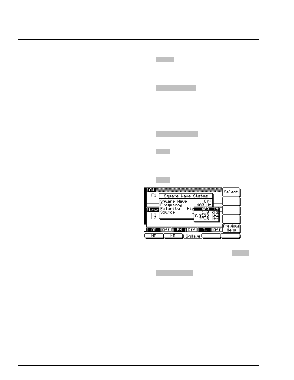
LOCAL (FRONT SIGNAL
PANEL) OPERATION MODULATION
Press On/Off to turn square wave modulation on
and off. Both the Square Wave status display and
the Square Wave modulation statu s area will reflec t
your selection.
Press
Internal/External to select the sourc e of the
modul ating signal. If yo u select Internal, the status
display sho ws Sour ce a s Inter nal an d Frequency
lists the actual source frequency. If you select External, the di splay sho ws Fr equency as Ext (extern a l)
and Source as Front or Rear to indic a te which input
connector is selected.
Press
L RF On/H RF On to select the polarity of the
signal that triggers the RF on.
Press
More to go to the additional menu.
Internal So urce Freq uen cy Select io n
If you have selected Inte rnal to use the modulating
signal from the inter nal sou rc e, then when you
press
More the menu shown below is displayed.
Use the cursor contr ol key to chose th e desired
modulating signal frequency, then press Select to
enter the selection into memor y. The Square Wave
status display will reflect your selection .
Press
Previous Menu to return to the initial
Square Wave Status Menu display.
3-66 681XXB OM
Page 95
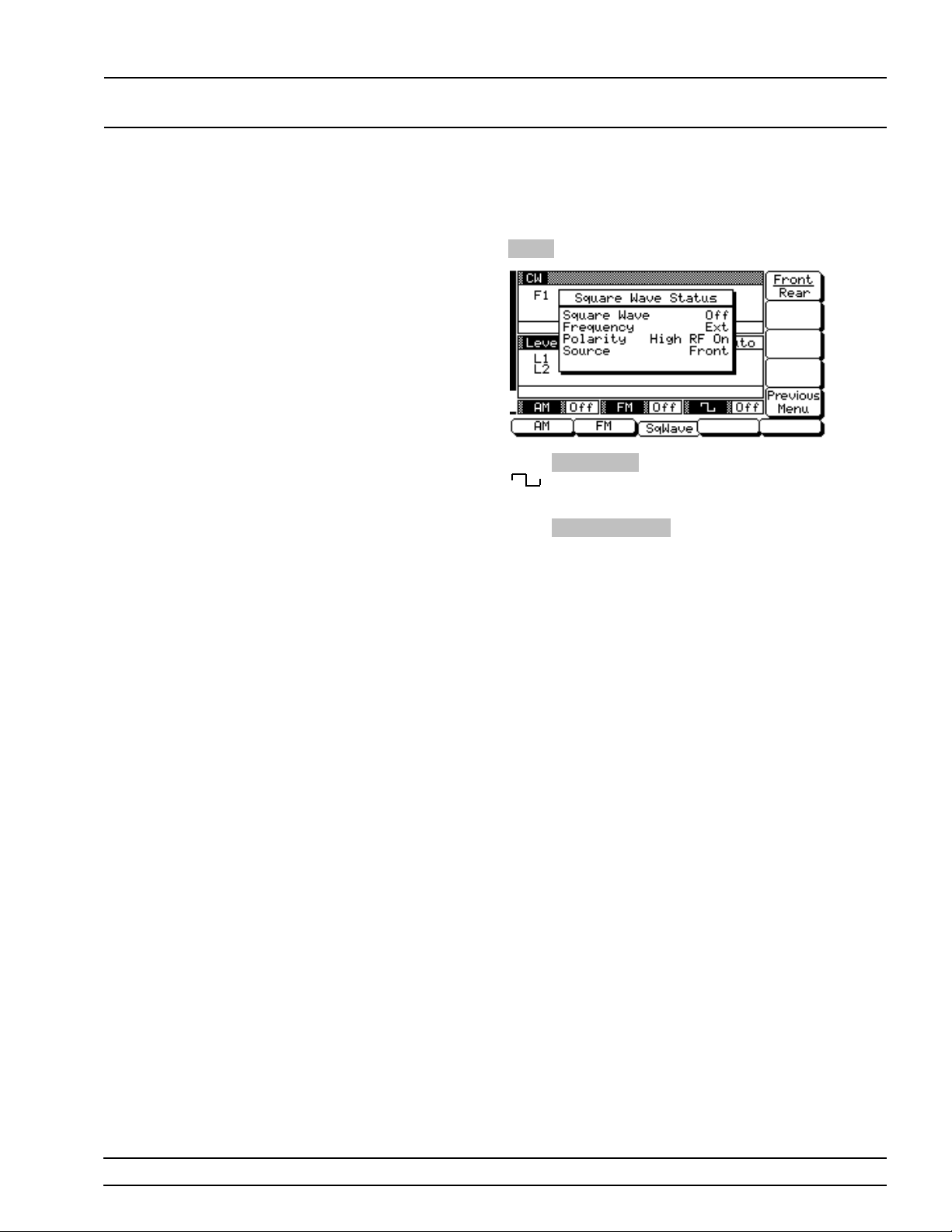
LOCAL (FRONT SIGNAL
PANEL) OPERATION MODULATION
Externa l So urce In pu t Conn ecto r Select ion
If you have selected Exter n al to use a modulating
signal from an exter nal sour ce , then when you pr ess
More the menu (below ) i s displayed.
Front/Rear to selec t th e fr on t or rear pan el
Press
IN connector. The Square Wave status display
shows your selection as Source.
Press
Previous Menu to return to the initial
Square Wave Status Menu display.
681XXB OM 3-67
Page 96
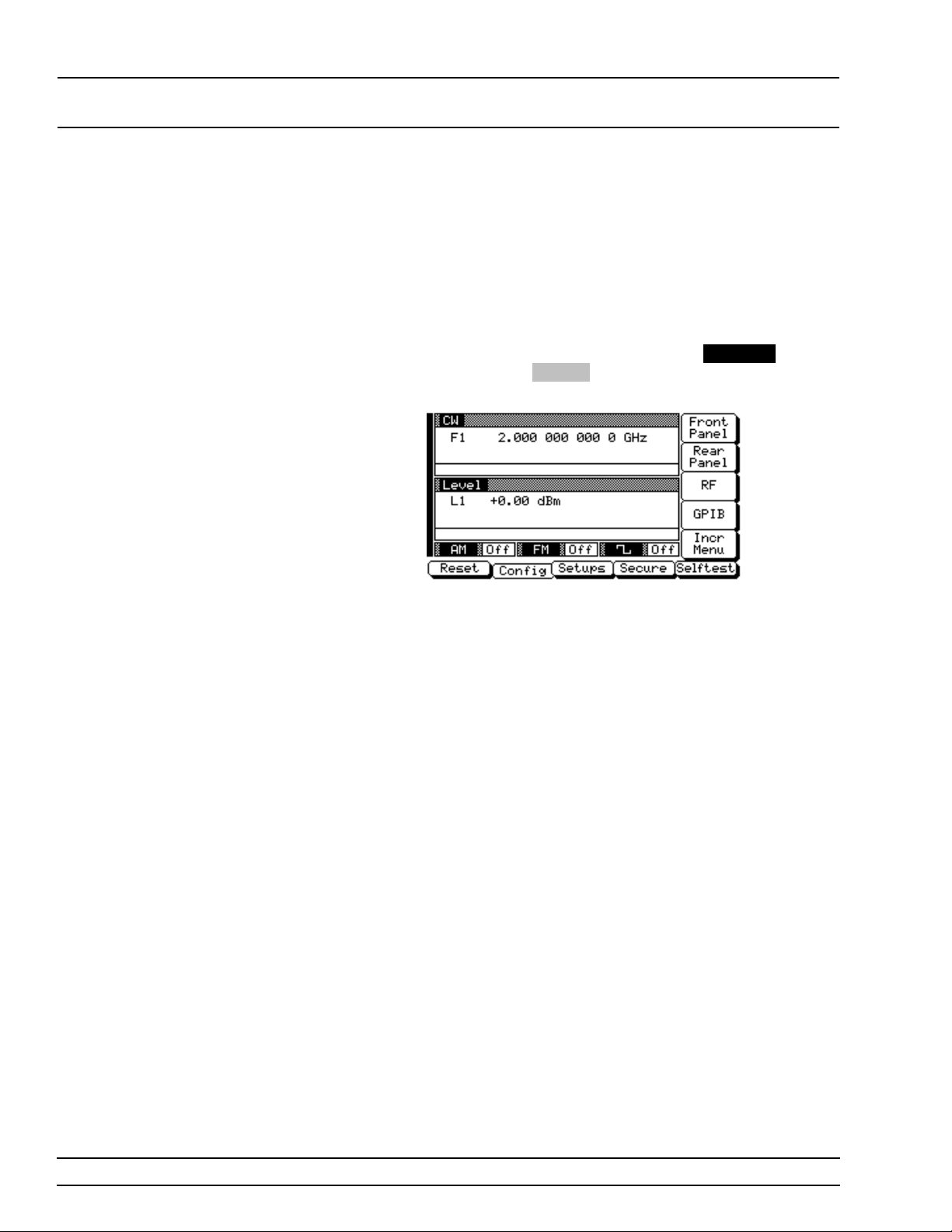
LOCAL (FRONT SYSTEM
PANEL) OPERATION CONFIGURATION
3-13
SYSTEM
CONFIGURATION
The system config uration func tion provide s menu s that let you set or
select instrument co nfigu ration items; for example, display inten sity,
polarity of blanking and video marker outputs, RF on or off during retrace or between steps, GPIB address and lin e termin ator, and incr ement sizes for frequ ency, power level, and time parameters. Use the
System Configu r ation men u map (Chapter 4, Figur e 4-13) to follow
the menu sequence s.
To go to the System Configuration menu , first press
System Menu display, press
(below) is displayed.
This menu lets you go to the Front Panel, Rear Pan el, R F, GPIB, and
Increment Configuration menus.
Config . The System Configu r atio n Men u
SYSTE M . At the
3-68 681XXB OM
Page 97
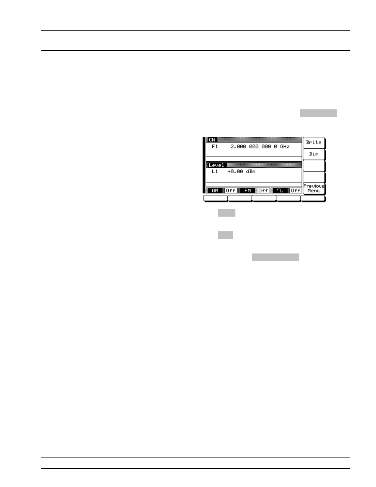
LOCAL (FRONT SYSTEM
PANEL) OPERATION CONFIGURATION
Configuring
the Front
Panel
Configurin g the front pane l of the sweep gener ator
involves adju sting the inte nsity level of the data display for ease of viewin g .
To go to the Configure Front Panel menu from the
System Configuration menu, press
The Configure Front Panel Menu (below) is displayed.
Press
Brite (repeatedly) to increase the in tensity of
the data display to the desired level.
Press
Dim (repeatedly) to decr ease the inten sity of
the data display.
Front Panel .
When done, press
System Configuration menu.
Previous Menu to return to the
681XXB OM 3-69
Page 98
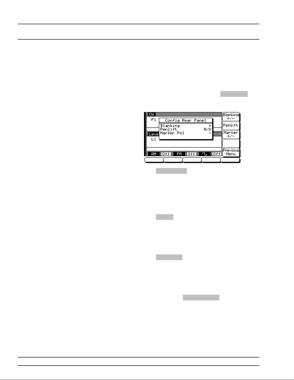
LOCAL (FRONT SYSTEM
PANEL) OPERATION CONFIGURATION
Configuring
the Rear
Panel
Configurin g the rear pane l of the sweep gener ator
consists of selecting the polarity of the retrace blanking, bandswitch blankin g , retrac e pen lift, and video
marker outputs.
To go to the Configure Rear Panel menu from the
System Configuration menu, press
The Configu re Re ar Pan el Menu (below) is displayed.
Press
Blanking +/– to select a +5V or –5V level for
the retrace and ban dsw itch blank ing outp uts. The
retrace blanking signal output is available at the
rear panel RETRACE BLANK OUT connector and
AUX I/O co nn ec tor. The bandswitch blanking sign a l
output is available at the rear panel AUX I/O connec-
tor. The display will reflect you r selection .
Rear Panel .
Press
Penlift to select normally-open (N/O) or nor-
mally-closed (N/C) contacts on the internal penlift
relay. The penlift relay outpu t, av ailable at the rear
panel PEN LIFT OUT connec tor, is used to lift a plot-
ter pen during retrace .Th e display will reflec t you r
selection.
Press
Marker +/– to select a +5V or –5V level for
the video marker outpu t wh en vide o mark er s are selected ON. The video mark er signal outpu t is available at the rear panel MARKER OUT connector and
AUX I/O co nnec tor. The display w ill refle ct yo ur se lection.
When done, press
System Configuration menu.
Previous Menu to return to the
3-70 681XXB OM
Page 99
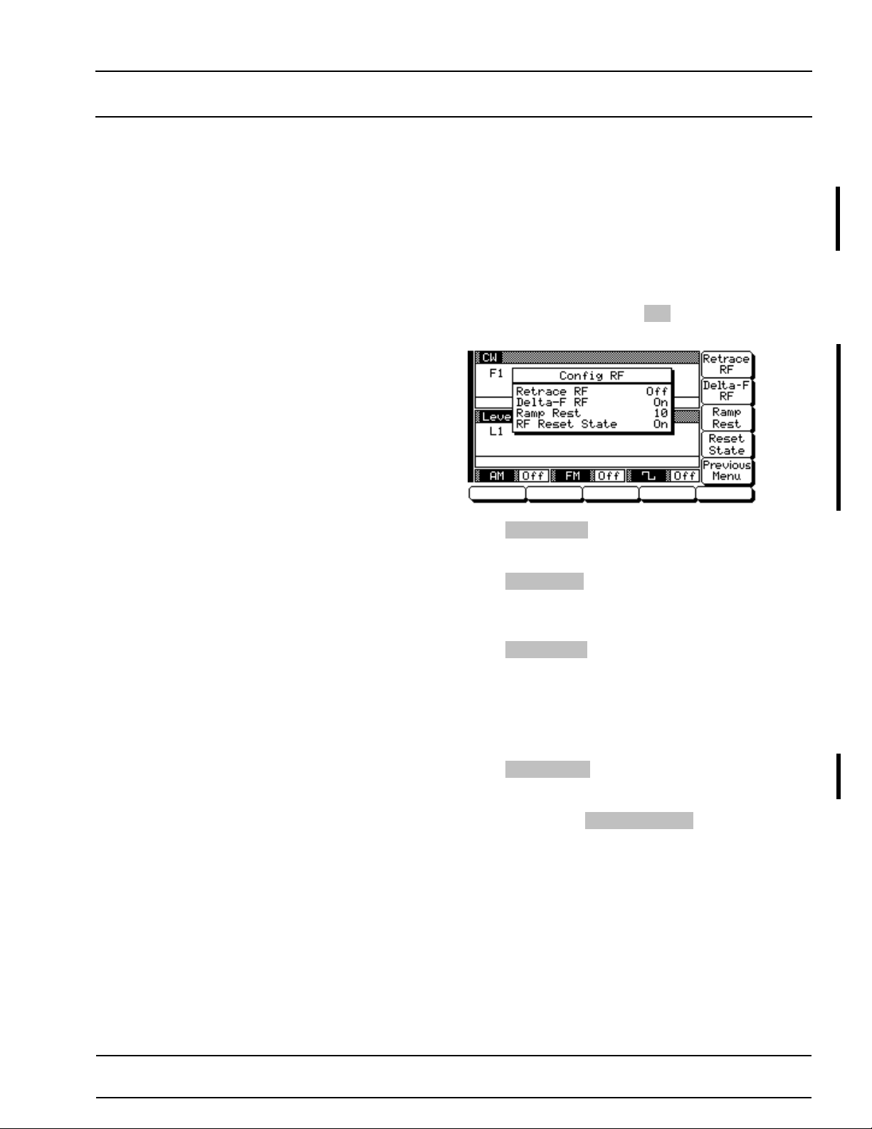
LOCAL (FRONT SYSTEM
PANEL) OPERATION CONFIGURATION
Configuring
the RF
Configur in g the RF of the 681XX B inv olv es selecting the state of the RF during retrace, dur ing fr equency swi tchin g in CW and step modes, and at
reset and selecting whe ther a sweep trig g ered by a
single or external trig g er should re st at the top or
bottom of the sweep ramp.
To go to the Configure RF menu from the System
Configuration menu, press
Menu (below) is displayed.
Press
Retrace RF to select RF On or Off durin g re-
trace. The display will ref lec t your selection .
Press
Delta-F RF to select RF On or Off during frequency switch in g in CW or step sweep modes. The
display will refle ct yo ur se lec tion.
RF . The Con fig ur e R F
Press
Ramp Rest to select 0 or 10 for the ramp
rest point for swee ps tr igger ed a single or external
trigger. 0 indicates that the sweep will re st at the
bottom of the sweep ramp; 10 indic ates that the
sweep will rest at the top of the sweep ramp. The
display will refle ct yo ur se lec tion.
Press
Reset State to select RF On or Off at re se t.
The display will reflect your selection.
When done, press
System Configuration menu.
Previous Menu to return to the
681XXB OM 3-71
Changed: November 1995
Page 100
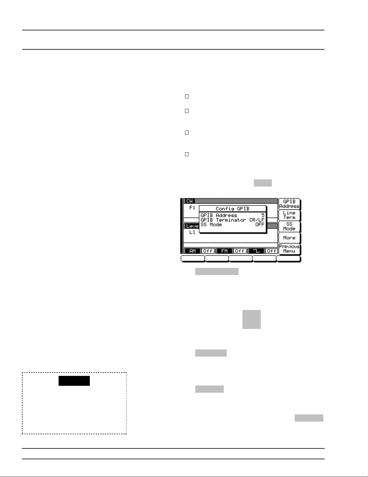
LOCAL (FRONT SYSTEM
PANEL) OPERATION CONFIGURATION
Configuring
the GPIB
Configur in g the GPIB for the sweep ge ne rator consists of the following:
Selecting a GPIB addre ss and the GPIB line
terminator for the sweep generator.
Placing the 681XX B in a sour ce lock mode for
operation with a WILTRON Model 360B Vector
Network Analy zer .
Selecting the model and GPIB address for the
power meter use d to crea te a user lev el fl atness correction power - offset table.
Selecting the external interface language for
remote operation of 681XXBs with Option 19.
To go to the Configure GPIB menu from the System
Configuration menu, press
GPIB Menu (below) is displayed.
GPIB . The Configure
SS MODE
When SS Mode is selected on, this
message is displayed (in the frequency mode title bar) on all menu
displays to remind the operator that
the 681XXB is in a source lock
mode.
Press
GPIB Address to chang e the address of the
681XXB on the bus (the sweep generator’s default
GPIB address is 5). Enter a new address, betw een 1
and 30, using the cursor contro l key or the data entry keypad and the terminator key
Hz
ns
ADRS
The new GPIB address will appear on the display.
Line Term to select a carriage return (CR) o r
Press
a carriage re tur n and line feed ( CR/LF ) as the GPIB
data delimiter. Consult the GPIB contr oller’ s manual to determine whic h da ta delimiter is require d.
Press
SS Mode to place the sweep gener ator in a
source lock mode for oper ation with a WI LTRON
Model 360B Vector Netw ork An aly zer. (Refer to
paragraph 7-4 for information pertaining to operating the 681XXB with a 360B VNA.) Pres s
again to turn the so urc e lock mode off .
SS Mode
3-72 681XXB OM
 Loading...