

Page 1

For economic measurement of SWR, loss/gain,
relative group delay and distance-to-fault
54100A/56100A
Scalar Network Analyzers
1 MHz to 110 GHz
Technical Data Sheet
•
ANRITSU Corporation
5-10-27, Minamiazabu, Minato-ku, Tokyo 106, Japan
Telephone +81-3-3446-1111
Telex J34372
Fax +81-3-3442-0235
Overseas Subsidiaries
•
USA
ANRITSU Company
1155 E. Collins Blvd. Richardson,
TX 75081, U.S.A.
Telephone +1-800-ANRITSU
Fax: +1-972-671-1877
•
Canada
ANRITSU Instruments Ltd
4-205 Matheson Blvd. East, Mississauga
Ontario, L4Z 3E3, Canada
Telephone +1-905-890-7799
Fax: +1-905-890-2290
•
Brazil
ANRITSU Electronica Ltda.
Praia de Botafogo 440, Sala 2401
CEP 22250-040, Rio de Janeiro, RJ, Brasil
Telephone +55-21-527-6922
Fax: +55-21-537-1456
•
UK
ANRITSU Ltd
200 Capability Green, Luton, Bedfordshire
LU1 3LU, United Kingdom
Telephone +44-1582-433200
Fax: +44-1582-731303
•
Germany
ANRITSU GmbH
Grafenberger Allee 54-56, D-40237
Düsseldorf 1, Germany
Telephone +49-211-968550
Fax:+49- 211-9685555
•
France
ANRITSU SA
9, Avenue du Québec, ZA de Courtaboeuf
91951 Les Ulis Cedex, France
Telephone +33-1-60-92-15-50
Fax: +33-1-64-46-10-65
•
Italy
ANRITSU SpA
Via Elio Vittorini, 129, 00144 Roma, Italy
Telephone +39-6-509-9711
Fax: +39-6-502-2425
Fax: +968-791697
•
Sweden
ANRITSU AB
Botvid Center 145 84 Stockholm, Sweden
Telephone +46-853470700
Fax: +46-853470730
Fax: +91-11-685-2275
•
Singapore
ANRITSU Pte Ltd
6, New Industrial Rd., #06-01/02, Hoe Huat
Industrial Building, Singapore 536199
Telephone +65-282-2400
Fax: +65-282-2533
•
Hong Kong
ANRITSU Company Ltd
Suite 812, 8/F, Chinachem Golden Plaza, 77 Mody
Road
Tsimshatsui East, Kowloon, Hong Kong, China
Telephone +852-2301-4980
Fax: +852-2301-3545
•
Korea
ANRITSU Corporation Ltd
Room No. 901, Daeo Bldg., 26-5, Yeoido-Dong,
Young Deung Po-Ku, Seoul, Korea
Telephone +82-2-782-7151 to 7156
Fax: +82-2-782-4590
Specifications are subject to change without notice.
15000-00010 rev A (TKO09/00)
Page 2

Distance-To-Fault
The most common failure in a microwave
radio link is the transmission line, the waveguide
and/or coaxial cables which connect radio
equipment to the antennas. With the 54100A
Series optional Distance-To-Fault (DTF) Software
you can install and maintain tower equipment
with confidence.
Anritsu’s precision calibration components
and low source harmonics provide industry
leading return loss (or SWR) accuracy. With
0.1% distance accuracy, you’re sure to identify
degraded components or moisture quickly –
before the problem causes a failure. Automatic
anti-aliasing software and windowing filters
ensure the peaks on the DTF display are really
there, not erroneous fault indications caused by
re-reflections.
With most elliptical waveguide components
meeting 30 dB return loss performance, it’s
absolutely critical that the precision load used
for calibration is of the highest quality to achieve
repeatable, accurate measurements. Using
poor quality 50 W loads for DTF calibration will
cause abnormally high test data variations
Specifications
The optional Distance-To-Fault software
displays impedance discontinuities versus
distance based on a swept frequency
measurement of transmission line mismatch.
The software is available by ordering Option 7
with 54100A Series Network Analyzers.
Measurements: Distance-To-Fault (meters or
feet), Return loss or SWR of fault.
Frequency Sampling:
256, 512, or 1024 frequency points.
Window Functions:
Hamming, 2-term, –42 dB sidelobes;
Blackman-Harris, 3-term, –67 dB sidelobes.
Anti-aliasing: Filtering of post detected data
rejects indications of false faults caused by
signal re-reflections during high reflection fault
conditions or out of band sweep on antenna
systems.
Distance Accuracy: < 0.1% of range or 2 mm
dependent upon knowledge of the propagation
velocity for the device under test and the
frequency sweep range.
Dynamic Range: > 80 dB, depending upon
calibration component return loss and operating
frequency range.
Return Loss Amplitude Accuracy: Effective
Directivity is dependent upon the return loss of
the precision termination used during calibration.
Distance Range: 1 to 5000 meters depending
on measurement frequency range and hardware
configuration.
Distance Resolution (of one fault): 0.4% of
total distance (256 frequency measurement
points), 0.2% of total distance (512 frequency
54100A Series optional softwareIntroduction to Anritsu Scalar Analyzers
2
Anritsu offer a comprehensive range of scalar
analyzers for economic network measurements
to 110GHz.
The 56100A scalar analyzer used in
conjunction with a 68C series synthesizer offers
the very best RF performance in a scalar
measurement system. The 68C series
synthesizer and 56100A analyzer communicate
over a private GPIB link to form an integrated
scalar measurement system.
The 56100A/68C scalar measurement
systems offers 10MHz to 50GHz frequency
coverage with –40dBc harmonics, up to
+17dBm levelled power and fully synthesized
sweeps. This combination is ideal where the
best possible frequency accuracy and dynamic
range are required.
Mixers and other frequency conversion
devices can also be characterised by using two
synthesizers in the system to generate
frequency sweeps with a fixed offset.
The 54100A series integrated scalar network
analyzers have built in crystal referenced
sources to provide an economical and compact
solution. They are ideal for production of devices
such as filters and amplifiers from 1MHz to
50GHz. Optional software adds; distance to
fault measurements for field testing of
waveguides, cables and antennas, relative
group delay software for economic filter
characterisation and precision return loss that
adds up to 20dB directivity improvement to
SWR measurements.
For scalar network measurements to 110GHz
both 54100A and 56100A are complemented
by the millimeter wave reflectometers.
measurement points), 0.1% of total distance
(1024 frequency measurement points).
Transmission Lines Supported:
• Coaxial Cable
• Waveguide
• Waveguide with Coaxial Cable Input
Transmission line loss and velocity factor are
corrected by the software. Waveguide dispersion
is corrected based on the cutoff frequency, fc.
For waveguide with coaxial cable input, a
special operating mode is utilized to
automatically compensate for the length of nondispersive coaxial cable in front of the
waveguide transmission line.
Distance-To-Fault Measurement
Accessories:
Anritsu Distance-To-Fault test systems utilize
standard diode detectors and measurement
accessories.
POWER DIVIDERS
These signal dividers are symmetrical, threeresistor tee designs that are used with the
Distance-To-Fault option and other applications
Distance-To-Fault mode
simplifies problem
identification. Superior
accuracy, sensitivity and
precision components ensure
that comparison
measurements clearly
indicate performance
degradation. Site
technicians easily locate
small problems before more
serious failures result.
The 56100A Scalar Network Analyzer operates with Anritsu’s
68C and 69B series synthesizers. The separate source
maximizes system performance and flexibility.
The 54100A Series Scalar Network Analyzers offer highly
integrated and economic network measurements
during maintenance test intervals. Instead of
saving time, technicians may find themselves
chasing non-existent problems.
3 dB
Frequency
Connectors
Attenuator
Range
Input Output
Model
1010-31 0.01 to 18 GHz N (m) N (f)
43KB-3 0.01 to 26.5 GHz K (m) K (f)
43KC-3 0.01 to 40 GHz K (m) K (f)
41V-3 0.01 to 60 GHz V (m) V (f)
54100A 56100A plus 68C synthesizer
Standard measurements Return loss (SWR), Return loss (SWR),
supported insertion loss/gain, power insertion loss/gain, power
Precision return loss
Additional measurements Distance-To-Fault
(optional) Relative group delay
Source Internal External
Anritsu 69A/B series
Anritsu 68B/C series
Anritsu 67XXA/B series
Wiltron 6600A/B series
HP 8340/8350 series
Two source control No Yes with synchronous sweeps
for mixer measurements
Max source power 10dBm @ 20GHz 13dBm @20GHz
17dBm option (68C source)
Harmonics, 2 to 20GHz -60dBc -60dBc (68C source)
Frequency accuracy Crystal controlled Synthesized
110GHz reflectometer
support Yes Yes
Autotesters and detectors Available to 50GHz Available to 50GHz
3.5 inch disk drive Yes No
Intelligent markers Yes Yes
GPIB as standard Yes Yes
Mean Time Between
Failure (MTBF) >10,000 hours >10,000 hours
World-wide service
and support Yes Yes
3
54100A NETWORK ANALYZER
RF CABLE
3 dB
ATTN
DETECTOR
POWER
DIVIDER
OPTION
ADAPTER
TRANSMISSION
LINE UNDER TEST
TERMINATION
APPLIED FOR
CALIBRATION
RAB
Power
Frequency
Connectors
Divider
Range
Input Output
Model
11N50B 50Ω DC to 3 GHz N (f) N (f)
11N75B 75Ω DC to 3 GHz N (f) N (f)
1091-29 50Ω DC to 18 GHz N (m) N (f)
K240B 50Ω DC to 26.5 GHz K (f) K (f)
K240C 50Ω DC to 40 GHz K (f) K (f)
V240C 50Ω DC to 65 GHz V (f) V (f)
Model
Frequency
Connector
Range
26N75A 75Ω DC to 3 GHz N (m)
26NF75A 75Ω DC to 3 GHz N (f)
28N50-2 50Ω DC to 18 GHz N (m)
28NF50-2 50Ω DC to 18 GHz N (f)
28S50-1 50Ω DC to 26.5 GHz WSMA (m)
28SF50-1 50Ω DC to 26.5 GHz WSMA (f)
28K50 50Ω DC to 40 GHz K (m)
28V50B 50Ω DC to 65 GHz V (m)
3 dB ATTENUATORS
PRECISION TERMINATIONS
Non-Ratio Operation, Coaxial
requiring two inputs to be combined into a
single output.
Maximum Input Power: +30 dBm
Terminations are required for calibration and are
occasionally used for terminating the output of
the coaxial cable under test.
This data sheet details the potential
applications and specifications of
the Anritsu scalar network analyzer
products. The reference table on pages
6 and 7 provides a guide to the
accessories that you will need for your
specific application.
Contents
Page 3
54100A Distance-To-Fault Software
Page 4
54100A Precision Return Loss Software
Page 5
54100A Relative Group Delay Software
Pages 6 and 7
54100A/56100A Measurement
Configuration Chart
Pages 8 and 9
54100A Specification
Pages 10 and 11
56100A Specification
Pages 12 and 13
Detector and Autotester Specification
Page 14
Millimeter Wave Reflectometer
Specification
Page 15
Accuracy of Scalar Measurements
Further information on Anritsu scalar
analyzers, or other Anritsu products, can be
found by contacting one of the offices listed
on the back cover. For a full list of sales
offices around the world, visit our web site at
www.anritsu.com
Page 3
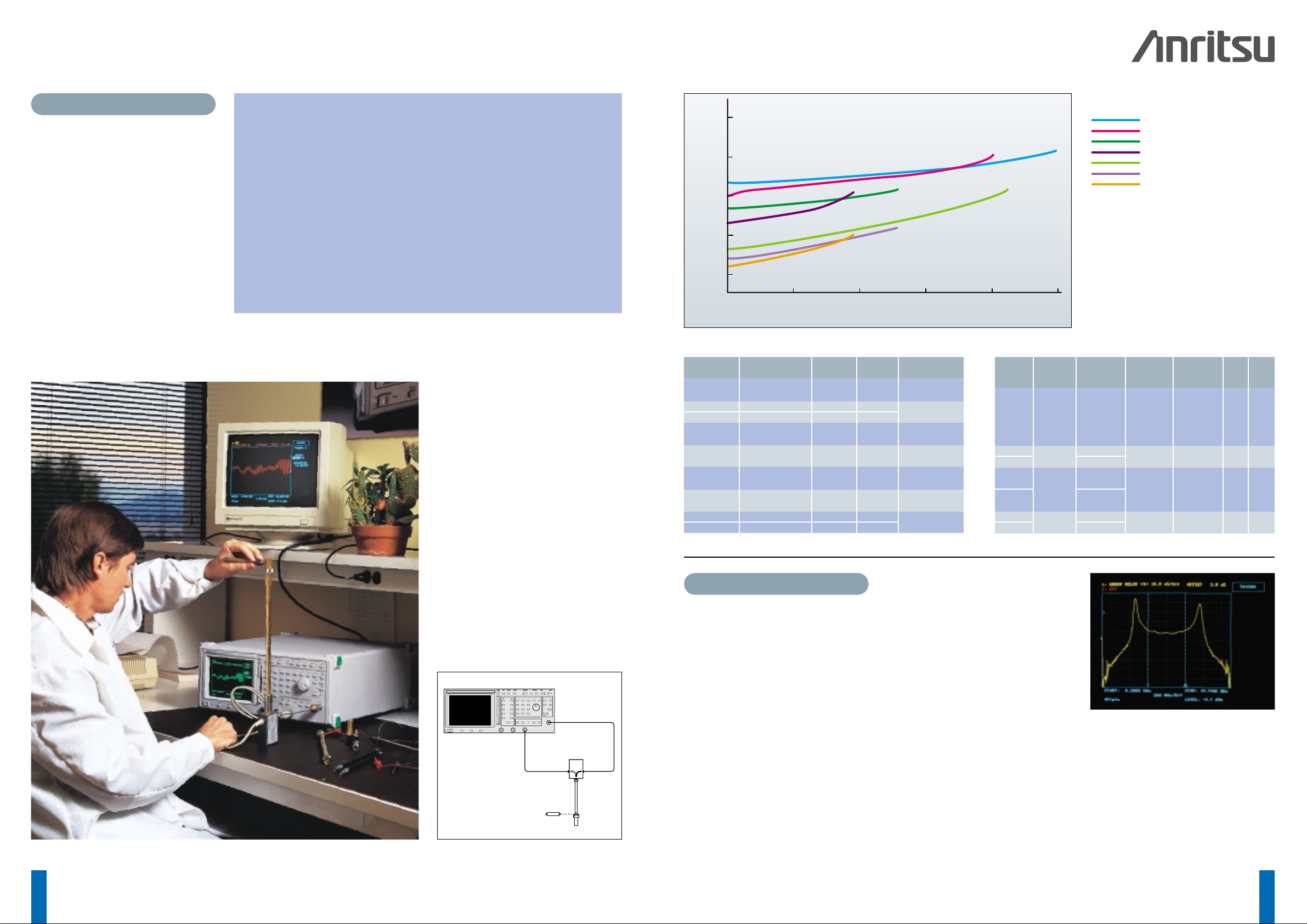
Relative Group Delay
Optional relative group delay software identifies
signal distortion caused by bandpass devices
such as filters, receivers, power amplifiers, and
up/down converters. Group delay is a key
cause of high Bit Error Rate (BER). Group
delay is important for 1) CDMA and spread
spectrum communications 2) phase radars 3)
high capacity satellite and terrestrial microwave
links 4) PAL and HDTV television components
and other RF systems sensitive to phase
distortion.
Group Delay results from deviation in the
rate of change of phase response versus
change in frequency, df/dw. It indicates that
different frequencies travel at different speeds
through an RF device. RF systems which
depend upon phase coded information suffer
degradation when group delay is excessive.
The growth in wireless communications
places a heavy demand on available frequency
spectrum. More efficient communications
standards have digital phase modulation with
high bits-per-hertz specifications and high
bandpass filter rolloff rates. Each of these
conditions make the communications more
susceptible to group delay induced bit error
rate problems.
The 54100A saves time and expense by
measuring group delay with the same,
inexpensive network analyzer as is used for
other tests.
Calibration requires only an RF path
normalization with a standard RF detector.
Relative group delay specifications assume
measurement of bandpass devices. Frequency
sweep must include at minimum 20 dBr of
transmission rolloff from mid-band response.
For best results, set the frequency sweep to
cover more than 20 dBr rolloff is suggested.
Relative Group Delay Accuracy:
Typically < 1ns, < 5.0% of peak-to-valley range
with noise averaged. Assumes the band
limiting device within the DUT meets minimum
phase shift design. Devices such as SAW
filters, microwave phase equalizers, and branch
line couplers will have additional uncertainty.
Calibration: A transmission path
normalization is required.
5
54100A Series software
4
Precision Return Loss
Precision Return Loss (PRL) is a technique
which uses vector signal addition principles to
extend the directivity of scalar network analyzer
(SNA) measurements. The 15 to 20 dB
directivity improvement allows accurate
verification and calibration of very high return
loss devices such as terminations, attenuators,
and adapters – components which are common
to almost every RF test bench.
Test bench components are susceptible to a
variety of problems including:
1) Repeated excess torque
2) Drops to the floor
3) Accumulation of dirt
Additionally, since adapters and attenuators
are not always labeled for frequency range, they
are occasionally used at frequency ranges
beyond their specification.
PRL finds these problems quickly. The
technique utilizes the same network analyzer
which is used for the production process: test
operators need only share an Airline and an
Offset SWR Autotester.
PRL Accuracy
When testing single port RF devices such as terminations, the principle uncertainty terms are
measurement directivity and channel accuracy. The directivity of a PRL measurement is limited by
the return loss of the precision airline. Channel accuracy includes noise effects, logarithmic
deviation, open/short cal uncertainty, linearity, and instrumentation stability. Additional second
order uncertainty terms such as test port match and source match are typically negligible.
Measurement Uncertainty (dB) = Channel Accuracy + Directivity Uncertainty
Measurement Uncertainty (dB) = - 0.5 - 20 log (1 + 10
- Ed/20
)
where, Ed = Airline Return Loss (dB) - Measured Return Loss (dB)
When measuring two port devices such as adapters and attenuators, an additional term (load
match) is required to account for the return loss of the precision termination which is attached to
port two of the device.
Measurement Uncertainty (dB) = - 0.5 - 20 log (1 + 10
- Ed/20
) -20 log (1 + 10
- Et/20
)
where, Et = Termination’s Return Loss (dB) - Measured Return Loss (dB)
With the implementation of ISO-9002, microwave test
specialists must perform verification of common test stand
components such as adapters and terminations on a daily or
weekly basis rather than at annual calibration cycles.
(Left) A technician tunes a precision termination in the
Precision Return Loss TUNING mode.
−20
−40
−60
0.01
10 20 30 40 50
Directivity Signal From Reference, dB
Frequency, GHz
N
WSMA
K
V
K Airline
WSMA Airline
N Airline
By utilizing the traceable performance of a Precision
Airline, the Precision Return Loss technique overcomes the
directivity limitations of standard SWR Autotesters (or
bridges), allowing accurate calibration of very low return
loss devices.
DUT Offset SWR Open Precision
Connector Autotester
Airline
Short Terminations
1
28A50
GPC-7 560-97A50-20 18A50 22A50
28A50-1
N male 560-97A50-20 18NF50 22N50 26N50
N female 560-97A50-20 18N50 22NF50 26NF50
SMA 28S50
male
560-98KF50-15 19SF50 22S50
28S50-1
SMA 28SF50
female
560-98KF50-15 19S50 22SF50
28SF50-1
3.5mm 19LF50
male
560-98KF50-15
(SC4127)
22K50 28K50
3.5mm 19L50
female
560-98KF50-15
(SC3588)
22KF50 28KF50
K male 560-98KF50-15 19KF50 22K50 28K50
K female 560-98KF50-15 19K50 22KF50 28KF50
1
Terminations are needed for adapter verification tests and other two port device testing.
Freq. Test Beaded
Dia. Lgth
Model Range Port Port SWR
(mm) (cm)
(GHz)
Connector Connector
1.003
(Test Port)
18A50 0.5 to 18 GPC-7 GPC-7 1.020 7 30
(Beaded
End)
18N50 N (m)
18NF50
0.5 to 18
N (f)
GPC-7 1.006 7 30
1.006
19S50 WSMA (m)
WSMA to 18 GHz
0.8 to 26.5
male 1.010
3.5 25
19SF50 WSMA (f)
to 26.5 GHz
19K50 K (m)
19KF50
0.8 to 40
K (f)
1.020 1.020 2.9 15
The 54100A utilizes transmission magnitude data to
calculate relative group delay using a Hilbert transform
software technique. No modulation is utilized. No aperture
settings are necessary and frequency converter ALC loops are
not disturbed during testing. The technique is applicable to
devices with minimum phase transfer functions.
RF OUTPUT
OFFSET
SWR
AUTOTESTER
PRECISION
AIR LINE
OPEN/SHORT
HERE FOR
CALIBRATION
54100A NETWORK ANALYZER
Z
x
DEVICE
UNDER
TEST
ABR
Component Connections for Precision
Return Loss Mode
For ISO-9000 based manufacturing, the
accuracy of production tests must be known.
The PRL measurement technique helps to
ensure test process compliance by verifying the
proper performance of test setup components.
The use of NIST traceable Precision Airlines
allow accurate calibration of those components.
Components For High Return Loss Device
Testing
Standard SWR autotesters are internally
terminated to a precision 50 ohm match. The
Offset SWR autotester replaces this 50 ohm
termination with a 15 dB or 20 dB offset
termination. This produces a readily measureable
reference vector.
During measurement, the S
11
reflection vector
of a high return loss will interfere with the
reference - creating a ripple pattern on the
display proportional to the DUT’s return loss.
The ripple pattern is automatically converted to
a return loss display trace by the precision
return loss mode’s software.
Legend
V-type SWR Autotester
K-type SWR Autotester
WSMA-type SWR Autotester
N-type SWR Autotester
K-type Offset SWR Autotester & K Airline
K-type Offset SWR Autotester & WSMA Airline
GPC-7 Offset SWR Autotester & N Airline
PRL ACCESSORY CONFIGURATION CHART AIRLINE SPECIFICATIONS
Page 4
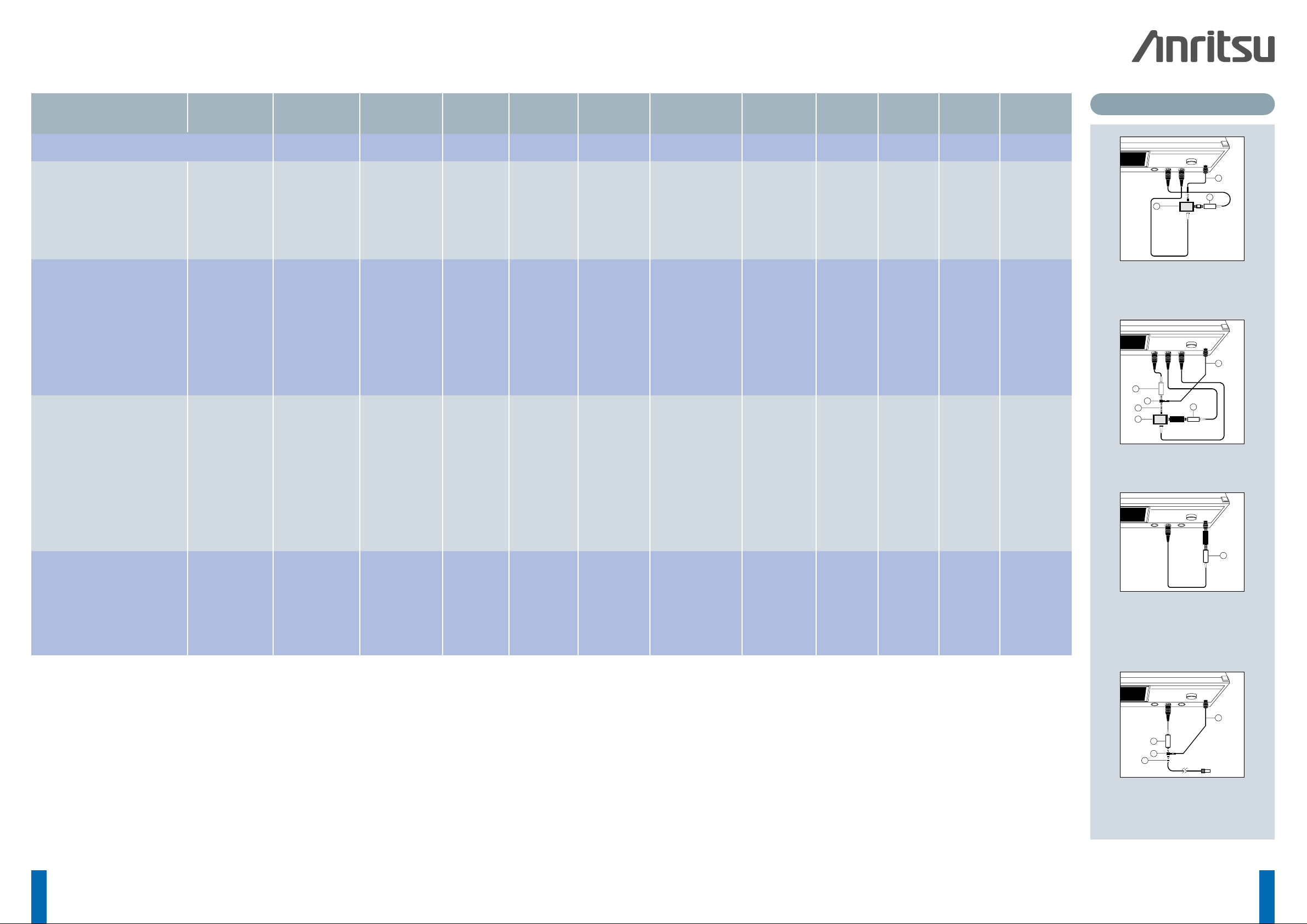
recommend use of a three resistor power
divider. Except for the 1091-29, the power
divider connection to the source output requires
a male-male adapter or an RF extension cable
with male connectors.
(I) 3 dB Attenuators, (J) DUT Adapters,
(K) Terminations
These components are used during coaxial
Distance-To-Fault applications. Waveguide DTF
applications may require a coaxial to waveguide
adapter.
(A) SWR Autotesters
For optimum accuracy, the SWR Autotester test
port must mate to the DUT's input connector. If
you must use an adapter at the SWR Autotester
test port, use a precision low SWR adapter to
minimize degradation of directivity.
(B) Detectors
One detector is required for transmission or DTF
measurements in non-ratio configurations. Ratio
measurements (monitors source output power)
require a second detector.
(C) Power Splitter
Two resistor power splitters are used for ratio
measurements and external leveling.
(D) Splitter Adapter
Adapter mates the power splitter output to the
SWR Autotester input for Ratio and/or externally
leveled measurements.
(F) Source Cable
In manufacturing applications, using the source
cable from the source output to the power
splitter input (or, in Non-Ratio applications to the
Non-Ratio Measurements: Eliminate one
detector and the power splitter for
measurements which do not need a source
power reference detector.
Ratio Measurements: Use ratio
techniques whenever source amplitude is
adjusted during the measurement process.
Gain (or Loss), Group Delay and Output
Power: An RF detector measures
transmission characteristics. Group Delay
measurement quality improves when a RF
splitter and a second RF detector are used
in a ratio configuration.
Distance-To-Fault: Faulty antenna
systems and transmission lines are easily
diagnosed with the 54100A Series optional
Distance-To-Fault mode.
SWR Autotester input) helps minimize long term
wear of the SWR Autotester’s test port
connector. The cable mates directly to power
splitter’s input. Connection directly to SWR
Autotesters requires a male-male adapter for
WSMA, K, and V type SWR Autotesters.
(G) Source Adapter
This adapter mates the source output directly to
the SWR Autotester input.
(H) Power Divider
Distance-To-Fault testing procedures
7
54100A/56100A Series Network Analyzer Configuration Chart
6
1
V to K interconnections require male (source) to female power splitter adapters. 2Also requires a source adapter. 3See page 12 to select appropriate test port heads.
Model Source DUT’s Input SWR Power Splitter Ext. Leveling Source Source Power 3 dB DUT Precision
Number Frequency Connector Autotester Detector Splitter Adapter Detector Cable Adapter Divider Attenuator Adapter Termination
Connection Diagram Reference Letter A B C D E F G H I J K
54107A 0.001 to 1.5 GHz 50 Ω N (f) 5400-6N50 5400-71N50 N241A50 34NN50A 75N50B N120-6 34NN50A 11N50B 1010-31 34NN50A 28NF50-2
50 Ω N (m) 5400-6NF50 5400-71N50 N241A50 34NN50A 75N50B N120-6 34NN50A 11N50B 1010-31 n/a 28N50-2
54109A 0.001 to 2.2 GHz
75 Ω N (f) 5400-6N75 5400-71N75 N241A75 34NN75B n/a n/a 34NN75B 11N75B 1010-53 n/a 26NF75A
54111A 0.001 to 3.0 GHz 75 Ω N (m) 5400-6NF75 5400-71N75 N241A75 34NN75B n/a n/a 34NN75B 11N75B 1010-53 n/a 26N75A
50 Ω GPC-7 560-97A50-1 560-7A50 1091-28 34NN50A 75N50B N120-6 34NN50A 1091-29 1010-31 34AN50 28A50-1
54147A 0.01 to 20 GHz
54137A 2 to 20 GHz 50 Ω N (f) 560-97N50-1 560-7N50B 1091-28 34NN50A 75N50B N120-6 34NN50A 1091-29 1010-31 34NN50A 28NF50-2
50 Ω N (m 560-97NF50-1 560-7N50B 1091-28 34NN50A 75N50B N120-6 34NN50A 1091-29 1010-31 n/a 28N50-2
56100A 0.01 to 20 GHz
+ 68147C 50 Ω SMA (f) 560-98C50A
3
560-7S50B K241B 1091-27 75KB50 NS120MF-6 34RSN50 K240B 43KB-3 K220B 28SF50-1
50 Ω SMA (m) 560-98C50A
3
560-7S50B K241B 1091-27 75KB50 NS120MF-6 34RSN50 K240B 43KB-3 n/a 28S50-1
50 Ω SMA (f) 560-98C50A
3
560-7S50-2 K241C K220B 75KC50 K120MF-15cm K220B K240C 43KB-3 K220B 28SF50-1
50 Ω SMA (m) 560-98C50A
3
560-7S50-2 K241C K220B 75KC50 K120MF-15cm K220B K240C 43KB-3 n/a 28S50-1
54169A 0.01 to 40 GHz
54163A 2 to 40 GHz 50 Ω K (f) 560-98C50A
3
560-7K50 K241C K220B 75KC50 K120MF-15cm K220B K240C 43KC-3 K220B 28KF50
50 Ω K (m) 560-98C50A
3
560-7K50 K241C K220B 75KC50 K120MF-15cm K220B K240C 43KC-3 n/a 28K50
56100A 0.01 to 40 GHz
+ 68167C 50 Ω V (f) 560-98VA50 560-7VA50 V241C
1
34VV50 n/a K120MF-15cm 34RVRK50 V240C
2
41V-3 34VV50 28VF50B
50 Ω V (m) 560-98VFA50 560-7VA50 V241C
1
34VV50 n/a K120MF-15cm 34RVRK50 V240C
2
41V-3 n/a 28V50B
50 Ω K (f) 560-98C50
3
560-7K50 K241C
1
K220B 75KC50 K120MF-15cm 34RVRK50 K240C
2
43KC-3 K220B 28KF50
54177A 0.01 to 50 GHz 50 Ω K (m) 560-98C50
3
560-7K50 K241C
1
K220B 75KC50 K120MF-15cm 34RVRK50 K240C
2
43KC-3 n/a 28K50
56100A 50 Ω V (f) 560-98VA50 560-7VA50 V241C 34VV50 n/a K120MF-15cm 34RVRV50 V240C 41V-3 34VV50 28VF50B
+ 68177C 50 Ω V (m) 560-98VFA50 560-7VA50 V241C 34VV50 n/a K120MF-15cm 34RVRV50 V240C 41V-3 n/a 28V50B
Connection Diagrams
F
B
A
B
C
D
A
DUT
F
B
DUT
DUT
B
F
B
H
Transmission Line
I
Under Test
Termination
Page 5
maximum values of successive sweeps or the
combination of the two. Ideal for acquiring data
on drift or gain variation against temperature.
Cursor Functions: Automatic cursor search
updates the bandwidth, minimum, or maximum
levels of the displayed trace, “X” dB above or
below the min/max point, or a selected
bandwidth. This function can be set to repeat
continuously.
Compression Test Automation: Determines
the gain compression point over the operating
frequency range of an amplifier by successively
incrementing the source power and measuring
the amount of compression until a preset “X” dB
limit is exceeded.
GPIB
Interface: IEEE-488.2 compliant interface with
integrated GPIB Plotter Control is standard on
all 54100A instruments. All front panel controls
are GPIB-controllable except power on/off. Front
panel configurable for instrument control or for
control of GPIB plotter.
Printer/Plotter
Plotter: The GPIB interface is compatible with
HPGL plotters. Display traces, markers, cursor,
and graticule information can be plotted.
Printer: Parallel printer interface is compatible
with the Cannon BJ85 and most Epson FXcompatible printers.
Internal Print and Plot Buffer: A new test
can be conducted while previously taken test
data are being printed or plotted from the
internal printer buffer. Portable printers may be
purchased locally or through Anritsu. When
purchased separately, a Centronics-to-
Measurements
The 54100A Series Network Analyzer include
models and measurement components from
1 MHz to 110 GHz.
Measurement Modes: Transmission (dB),
Return Loss (dB), Precision Return Loss (dB),
SWR (linear SWR), Power (dBm), optional
Distance-To-Fault (feet or meters) and Relative
Group Delay (ns),
Analyzer
Dynamic Range: -55 dBm to +16 dBm,
Autozeroing implements AC detection on a
single cycle per sweep basis using Anritsu 560
Series or 5400 Series Detectors and SWR
Autotesters. DC detection is used during the
sweep to improve accuracy and avoid disturbing
automatic leveling controls in the device under
test. Auto-zeroing can be disabled.
Inputs: Three. Two standard inputs, A and B,
with an optional third reference channel, R
(Option 5). Anritsu 560 Series and 5400 Series
Detectors and Autotesters are designed to
operate with the 54100A Network Analyzer. For
millimeter wave applications, the 5400 Series
Multiplier/Reflectometers provide integrated
reference and return loss detection.
Channels: Two channels are used to select
and simultaneously display any two inputs from
A, B, or R. The inputs can also be displayed as
ratios A/R or B/R.
Display Resolution:
Horizontal: 51, 101, 201, or 401 points.
Vertical: 0.025 dB, 0.0025 ns
Graticule: Ten vertical divisions. Horizontal axis
automatically scales in frequency increments of
1, 2, 5. Graticule On/Off button turns all
graticule lines off. Tick marks remain on axis to
indicate graticule position.
Vertical Scaling:
Resolution: 0.1 dB(m) to 10 dB(m) per division.
Independent control for each channel 0.1 to 100
ns per division.
Offset range: -99.9 dB to +99.9 dB,
-99.9 to +99.9 ns.
Autoscale: Automatically selects offset and
resolution to provide optimum display of test data.
External VGA Monitor Output: Rear panel
connection is provided to drive a VGA color
display. Trace colors are menu selectable.
Cursor: The numerical amplitude of the test
data and frequency are displayed for both
channels. Display range -99.9 to +99.9 dB or ns.
Relative Cursor: Displays the amplitude and
frequency differences between the Cursor and
Relative Cursor for both channels.
Cursor Functions: Automatic cursor searches
for trace Maximum, Minimum, dB Level, dB
Bandwidth, Next Marker, and Active Marker may
be performed.
Centronics Printer Interface Cable will be
needed for operation with the 54100A.
I/O Connections
Horizontal Sweep Ramp Output: 0 to +10 V
nominal.
GPIB: Connects 54100A to controller or plotter.
Rear panel GPIB connector.
Parallel Printer (Centronics): Connects
54100A to printer. Rear panel.
VGA Output: Connects 54100A to exter nal
VGA color display (not supplied). Rear panel 15
pin “D” connector.
External Leveling: Option 6 adds external
leveling capability. Levels output power at
remote test position. (Rear panel BNC female
connector).
General
Self Test: Performs a self test every time power
is applied or when SELF TEST push button is
pressed. If an error is detected, a diagnostic
code appears, identifying the cause and location
of the error.
Temperature Range:
Operating: 0°C to +50°C
Storage: -40°C to +70°C
Electromagnetic Compatiblity: Complies
with European Community requirements for CE
marking
Power: 115V +10%/-20%, 230V +10%/-20%,
48-440 Hz, 300 VA maximum
Dimensions: 177 H x 426 W x 476 D mm + 51
mm for feet (7 H x 16.75 W x 18.75 D in. + 2.0
in. for feet)
Weight: Nominally 18 kg (39 lb.), 54147A
Display Data Correction: System frequency
response errors are removed from
measurements with a through-line transmission
calibration and an open-short reflection
calibration. Calibration data is stored at 0.002
dB resolution over the selected frequency range.
interpolation is used to maintain calibration as
frequency sweep range is decreased.
Smoothing: Filtering, adjustable in five levels,
to reduce noise and interference on low-level
traces. Channels may be independently set.
Averaging: 2, 4, 8, 16, 32, 64, 128, or 256
successive traces may be averaged together to
remove unwanted noise. Channels may be
independently set.
Limit Lines: Two limit lines, either single value
or multi-level segmented, for each trace.
Complex lines may be made from up to 10
individually-editable segments.
Trace Mask: A swept measurement can be
stored to a graticule Trace Mask for visual
comparison to later measurements.
Save/Recall: Thirteen sets of front-panel setups and thirteen sets of trace memory can be
stored in non-volatile instrument memory. Stored
set-ups may be previewed on the CRT or
printed prior to selection. Non-volatile memory
can be erased for security purposes.
3.5 Inch DOS Disk Drive: Instrument
configurations and trace data can be stored on
a MS-DOS
®
compatible 3.5 inch, 1.44 MB
floppy disk. Trace Data can be stored in a
standardized ASCII format which easily reads
into common PC spread sheets and word
processing software.
Source
Frequency Range: 1 MHz to 50GHz internal
(see millimeterwave reflectometer for 110GHz
coverage).
Start-Stop: Sweeps from start frequency to
stop frequency.
Center-Width: Sweeps from center - (width/2)
to center + (width/2)
Alternate Sweep: Sweeps alternately between
frequency ranges set differently for Channel 1
and Channel 2.
CW: Provides single frequency output (both
channels turned off).
Frequency Resolution:
RF Models (54107A, 54109A, 54111A): ±10 kHz
Microwave Models: ±100 kHz
Start Frequency Accuracy:
RF Models (54107A, 54109A, 54111A): ±100 kHz
Microwave Models to 20 GHz: ±200 kHz
Microwave Models, 20 to 40 GHz: ±400 kHz
Microwave Models, 40 to 50 GHz: ±800 kHz
Sweep Time, Single Band: Typically less than
70 ms for single channel with 101 point
horizontal resolution, depending on frequency,
Measurement System Options:
Option 1 Rack Mounting with Slides
Option 2 70 dB RF Step Attenuator
Option 2A 70 dB, 20 GHz Step Attenuator
Option 2B 70 dB, 26.5 GHz Step Attenuator
Option 2C 70 dB, 40 GHz Step Attenuator
Option 2D 70 dB, 50 GHz Step Attenuator
Option 4 75 ohm source output.
(Available to 3.0 GHz)
Option 5 Add Reference Channel
Option 6 Add Exter nal Leveling
Option 7 Inter nal Distance-To-Fault Software
Option 8 Relative Group Delay Software
Option 12 Add Front Panel Cover
Option 13 Add Front Mounted Handles
Option 16 +15 V DC Supply for Millimeter
Wave Source Modules (Available
with ≤ 20 GHz Models only)
Option 25 Maintenance Manual
Option 26 Extra Operation and GPIB
Programming Manual
Option 33 Ink-Jet Printer
Transit Case:
760-183 Transit Case: Hard shell case with
custom foam inserts and carrying handle for
maximum protection of the 54100A.
averaging, and smoothing settings. Trace
update time is typically 130 ms with similar
system settings.
Residual FM:
1 MHz to 20 GHz < 10 kHz Peak
20 GHz to 40 GHz < 20 kHz Peak
40 GHz to 50 GHz < 40 kHz Peak
Measured in 30 Hz to 15 kHz post-detection BW.
Output Power: Maximum guaranteed leveled
output power is model dependent. Typical
unleveled output power exceeds the specified
leveled output power. Operation with unleveled
output power degrades rated specifications and
is not recommended.
Reverse Power Protection: Up to 1 Watt.
Power Level Accuracy: ±1 dB, leveled. ±3.0
dB for models above 20 GHz, and ± 4.0 dB for
50 GHz models. Add ±0.2 dB for Option 4-75Ω
output.
Power Level Accuracy, Attenuator: Optional
70 dB Step Attenuator (10 dB steps). Leveled
power accuracy degrades by ±1.5 dB for
models below 20 GHz and ±1.9 dB for 20 GHz
models.
Power Level Control, Internally Leveled:
Front panel control adjusts power over a 10 dB
range (up to 20 dB in some models) or from
-70.0 dBm to maximum leveled power when
Option 2, 2A, 2B, 2C or 2D 70 dB Step
Attenuator is installed.
Power Level Control, Externally Leveled
(Option 6): Front panel control adjusts power
range determined by external leveling detector
output. Flatness determined by leveling detector
and coupler characteristics.
Leveling (With External Detector): Levels
output power at DUT input positions other than
near the 54100A source output. A leveling
detector tracks the RF power level by providing
a positive or negative polarity detected signal of
30 to 200 mV to a rear panel BNC connector.
Leveled Power Variation:
1.0MHz to 1.0 GHz ± 0.3 dB ±1.0 dB, Opt 2
1.0MHz to 2.0 GHz ± 0.4 dB ± 1.1 dB, Opt 2
1.0MHz to 3.0 GHz ± 0.6 dB ± 1.3 dB, Opt 2
10.0 MHz to 20 GHz ± 0.8 dB ± 1.0 dB, Opt 2A
10.0 MHz to 26.5 GHz ± 1 . 0 dB ± 2.5 dB, Opt 2B
10.0 MHz to 32 GHz ± 2.0 dB ± 2.0 dB, Opt 2C
10.0 MHz to 40 GHz ± 2.0 dB ± 2.0 dB, Opt 2C
10.0 MHz to 50 GHz ± 3.0 dB ± 3.0 dB, Opt 2D
Add ± 0.2 for 75 Ω sources
Markers: The numerical amplitude of the test
data and frequency are displayed. Markers
remain fixed at the set frequency, independent
of displayed sweep frequency range.
Application Functions
Application functions speed and ease the task
of characterizing antennas, filters, amplifiers, and
other microwave devices.
Min/Max Hold: Save the minimum and
9
54100A Specification
8
Model
Frequency
Range
Harmonic
2
Non Harmonic
Source SWR
1
(Leveled)
Output Power
1
Connector
54107A 0.001 to 1.5 GHz -40 dBc -60 dBc
< 1.5
12 dBm, 50 Ω
10 dBm, 75 Ω
54109A 0.001 to 2.2 GHz -40 dBc -60 dBc
< 1.5
12 dBm, 50 Ω
10 dBm, 75 Ω
N (f)
54111A 0.001 to 3 GHz -40 dBc -60 dBc
< 1.5
12 dBm, 50 Ω
10 dBm, 75 Ω
N (f)
54147A 0.01 to 20 GHz
-60 dBc, > 2 GHz
-40 dBc, < 2 GHz
-60 dBc, > 2 GHz
-50 dBc, < 2 GHz
< 1.8 10 dBm, 50 Ω
N (f)
54137A 2 to 20 GHz
-60 dBc, > 2 GHz
-40 dBc, < 2 GHz
−60 dBc, > 2 GHz
−50 dBc, < 2 GHz
< 1.8 10 dBm, 50 Ω
N (f)
54169A 0.01 to 40 GHz
-60 dBc, 2-20 GHz
-40 dBc, > 20 GHz
-40 dBc, < 2 GHz
−50 dBc, > 2 GHz
−50 dBc, < 2 GHz
< 1.8 4.0 dBm, 50 Ω
K (f)
54163A 2 to 40 GHz
-60 dBc, 2-20 GHz
-40 dBc, > 20 GHz
-40 dBc, < 2 GHz
−50 dBc, > 2 GHz
−50 dBc, < 2 GHz
< 1.8 4.0 dBm, 50 Ω
K (f)
54177A 0.01 to 50 GHz
-60 dBc, 2-20 GHz
-40 dBc, > 20 GHz
-40 dBc, < 2 GHz
−50 dBc, > 2 GHz
−50 dBc, < 2 GHz
< 2.0 1.0 dBm, 50 Ω
V (f)
1
At 25°C, internally leveled. Attenuator Options 2 through 2C reduce output power specification by 3.0 dB; 2D, 4.0 dB. 2Loaded at 50 Ω
N (f)
Page 6
WSMA, or K Connector®test ports, all with high
directivity. The 560-98C50A Convertible SWR
Autotester tests devices with SMA, 3.5 mm or K
Connectors.
GPIB
Interface: IEEE-488 interface is standard. All
front-panel controls are GPIB controllable
except power on/off and CRT intensity.
Pass-through commands allow control of the microwave signal source through the 56100A
GPIB port.
Data Transfer: The 56100A does not require
an external controller; nevertheless, it is capable
of providing high speed data transfer of test
data and normalization data to an external GPIB
controller.
Printer/Plotter
Plotter: The GPIB interface is compatible with
HPGL plotters. Display traces, markers, cursor,
and graticule information can be plotted.
Printer: Parallel printer interface is compatible
with the Canon BJ85 and most Epson
FX-compatible printers.
Internal Print and Plot Buffer: A new test
can be conducted while previously taken test
data are printed or plotted from the internal
printer buffer.
Portable printers may be purchased locally or
through Anritsu. When purchased separately, a
Centronics-to-Centronics Printer Interface Cable
will be needed for operation with the 56100A.
I/O Connections
Horizontal Sweep Ramp Input: 0 to +10V
nominal, +12V maximum
Sequential Sync Input: +3.5V to +10V blanks
trace during synthesizer retrace or
bandswitching. -3.5V to -10V defines a marker
which when in the range of -8V to -10V is an
active marker. Rear panel BNC connector.
Retrace Blanking Input: +5V blanks traces
during retrace. Rear panel BNC connector.
Video Marker Input: ±1V to ±10V peak input.
Rear panel BNC connector.
System GPIB: Connects 56100A to GPIB.
Rear panel GPIB connector.
Dedicated GPIB: Connects 56100A to signal
source and plotter. Rear panel GPIB connector.
Parallel Printer (Centronics): Connects
56100A to printer. Rear panel.
AUX I/O: Connects 56100A to compatible
source. Rear panel.
General
Self Test: Performs a self test every time
power is applied or when SELF TEST
pushbutton is pressed. If an error is detected, a
diagnostic code appears, identifying the cause
and location of the error.
Electromagnetic Compatibility and
Susceptibility:
Compliant with European Community
requirements for CE marking.
Frequency Accuracy: Same as synthesizer
frequency accuracy specification.
Inputs: Four inputs, A, B, R1, and R2 accept
detected outputs from Anritsu 560 Series
Detectors and SWR Autotesters.
Dynamic Range: 76 dB (-60 dBm to +16
dBm) on all channels, useable to -65 dBm.
Data Correction: System residuals, including
the average of open and short reflections, are
stored during normalization for automatic
subtraction from test data.
Normalization: During the normalization
sequence, each trace is stored with 0.002 dB
resolution over any user-selected frequency
range. Normalization data are automatically
interpolated for ranges less than the original
normalized range.
Save/Recall: Nine sets of front-panel settings
can be stored for later recall. All stored data can
be previewed on the CRT or printer output prior
to selection. Four of the setups include their
own calibration data.
Display
Channels: Two channels are used to select
and simultaneously display any two inputs from
A, B, R1, or R2. The same inputs can be
displayed as ratios of A/R1, A/R2, B/R1, or B/R2.
Alternate Sweep: Displays alternate sweeps
between the current front-panel setup and any
of nine stored setups.
Graticule: Ten vertical divisions. Horizontal
divisions are set
automatically in frequency increments of a 1, 2,
5 sequence. Graticule On/Off control turns all
graticule lines off. Tick marks remain on axis to
indicate graticule position.
Display Resolution:
Horizontal: 101, 201, or 401 points over
selected frequency range.
Vertical: 0.005 dB
Limit Lines: Two lines, either straight or
complex, for each trace. Complex lines may be
made from up to 10 segments. Measurement
data may be compared with limit lines for
Pass/Fail testing.
Scaling:
Resolution: 0.1 dB to 10 dB per division in 0.1
dB steps with independent control for each
channel.
Offset Range: -99 dB to +99 dB in 0.1 dB
steps.
Autoscale: Automatically selects offset and
resolution to provide optimum display of test data.
Trace Update Time: Typically less than 100
ms, varying with frequency range and the
averaging and smoothing settings.
Smoothing: Off, Minimum, and Maximum
selections use analog techniques to reduce
noise on low-level traces. Trace update time is
automatically adjusted for any combination of
averaging and smoothing.
Averaging: 4, 8, 16, 32, 64, 128, or 256
successive traces can be averaged to smooth
the trace display.
CRT Intensity: Continuously adjustable from
off to bright.
Markers and Cursor
Markers: Displays up to ten numerically
identified markers (F1 thru F9) generated by the
68C or 69B Series Synthesizers. When a marker
is selected as “Active”, the cursor can be
moved directly to the marker. The cursor can
also be moved sequentially through markers
until the desired marker is reached.
Cursor: Continuously variable with the tuning
knob. The frequency and amplitude of test data
at the cursor on both traces are digitally
displayed.
Relative Cursor: Displays the frequency and
amplitude difference between the main Cursor
and the Relative Cursor for both traces. A menu
selection reverses the position of the two
cursors.
Cursor Min/Max: Automatically moves the
cursor to the minimum or maximum value of
test data on either trace.
Cursor “X” dB: Automatically moves cursor on
either trace to an amplitude that is equal to the
entered value of “X” dB or dBm.
Cursor “X” Bandwidth: Automatically displays
cursors to the right and left of the cursor at the
frequencies where the test data are equal to the
entered value of “X” dB. The frequencies of the
low and high cursors and the bandwidth
between them are displayed.
Cursor Next Marker: Moves cursor to next
highest frequency marker.
Cursor Active Marker: Moves cursor to the
frequency of the active marker.
Source
Internal software provides system compatibility
with the following sources.
Anritsu 69A/B Anritsu 68B/C
Anritsu 67XXA/B Anritsu 6600A/B
HP 8340/8350 series
See individual source data sheet for
specifications.
Superior Accuracy
The 56100A is designed to provide superior
accuracy to 110 GHz. When used with a
synthesizer’s step sweep mode, all
measurement frequencies, including markers
and cursors, have synthesizer accuracy. The
exceptional return-loss accuracy is attributable
to the low synthesizer harmonics and spurious,
the high directivity and exceptional test port
match of the Anritsu SWR Autotesters. To avoid
the use of error-producing adapters, SWR
Autotesters are available with GPC-7, Type N,
11
56100A Specification
10
High Performance
Scalar Measurements
The Anritsu 56100A Scalar Network Analyzer
combined with a Anritsu 68C Series or 69B
Series Synthesizer, forms a powerful swept
frequency measurement system for both
production and design applications.
Measure insertion loss, insertion gain, or RF
power with 76 dB dynamic range over the 10
MHz to over 50 GHz frequency range—the
widest frequency range available in coax.
Measure device match as return loss in dB or as
SWR.
Separate detectors can be used on all four
inputs for multiple transmission measurements
on duplexers or matched amplifiers. Direct
detection allows simultaneous RF power
measurement at different frequencies for
example, at the RF, IF, and LO frequencies of
mixers and converters.
Versatile
Transmission and reflection measurements can
be viewed simultaneously. Both traces can be
scaled independently in dB, dBm or SWR.
Measurement of the ratio of two detector inputs
may be applied to either channel for enhancing
accuracy or for viewing differences. Built-in
calibration allows subtraction of the unwanted
transmission frequency response and the
average of open/short reflections.
A Volt Mode is available for displaying voltage
(with Volt Mode Adapter Cable). A 0 to 10 Volt
Sweep Ramp Output Mode is also available.
These modes, combined with a versatile Trace
Memory Mode, allow easy testing of VCOs, PIN
diodes, and detectors.
Measurements
Measurement systems using the 56100A Scalar
Network Analyzer include components from 1
MHz to 110 GHz.
Function: The 56100A has four detector inputs
and two independent channels for measurement
and display of detected RF power from Anritsu
560 Series Detectors and SWR Autotesters.
Two independent channels display RF power
(dBm), Transmission Gain or Loss in (dB), or
reflected power. Voltage may be displayed with
optional Volt Mode Adapter Cable.
Measurement Modes: Measures and displays
in dB swept transmission and return loss
characteristics. Power is displayed in dBm.
Complete measurement parameters for all
modes are displayed.
Frequency Range: 10 MHz to over 50 GHz in
coax using Anritsu 560 Series Detectors and
SWR Autotesters. Waveguide measurement
components to 110 GHz support transmission,
reflection, and power measurements.
Temperature Range:
Operating: 0°C to +50°C
Storage: -40°C to +70°C
Power: 100/120/220/240V AC +5%/-10%,
48-63 Hz, 100 VA maximum
Dimensions: 77 H x 426 W x 476 D mm +51
mm for feet(7 H x 16.75 W x 18.75 D in. +2.0
in. for feet)
Weight: 18 kg (39 Ib.)
Options
Transit Case
40010 Transit Case: Hard shell case with
custom foam inserts and carrying handle for
maximum protection of the 56100A.
Option 1 Rack Mounting 19 inch rack mount
with slides optional
Option 12 Front Panel Cover
Option 13 Front Mounted Handles
Option 25 Maintenance Manual
Option 26 Extra Operation and GPIB
Programming Manual
Option 33 Ink-Jet Printer
Page 7
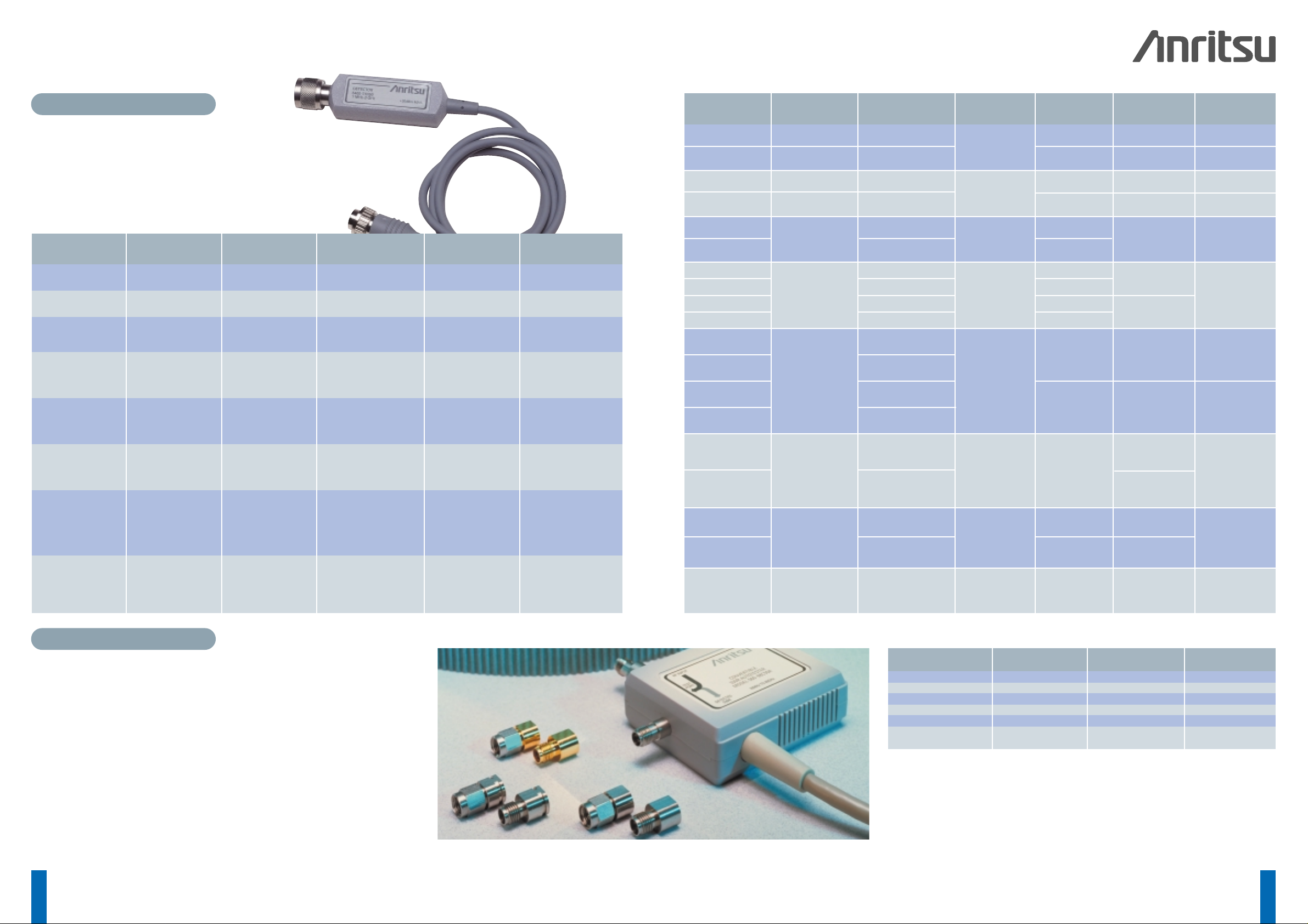
13
Detectors and SWR Autotesters
0.001 to 3 GHz
50 Ω
< 1.08, 2 GHz
< 1.11, > 2 GHz
N (f)
0.001 to 3 GHz
< 1.08, 2 GHz
< 1.11, > 2 GHz
N (f)
0.001 to 3 GHz
75 Ω
< 1.10, 2 GHz
< 1.17, > 2 GHz
N (f)
0.001 to 3 GHz
< 1.10, 2 GHz
< 1.17, > 2 GHz
N (f)
0.01 to 18 GHz
50 Ω
< 1.10, 2 GHz
N (f)
< 1.17, 2 GHz
0.01 to 18 GHz
50 Ω
< 1.10, 8 GHz
N (f)
< 1.17, > 8 GHz
< 1.17, 8 GHz
< 1.27, > 8 GHz
0.01 to 26.5 GHz
50 Ω
< 1.14, 8 GHz
< 1.22, 18 GHz
< 1.27, ≤ 26 GHz
Ruggedized
K (f)
< 1.14, 8 GHz
< 1.22, 18 GHz
< 1.27, ≤ 26 GHz
Ruggedized
K (f)
0.01 to 40 GHz
50 Ω
< 1.14, 8 GHz
< 1.26, 18 GHz
< 1.29, 26.5 GHz
< 1.33, 32 GHz
< 1.38, 40 GHz
Ruggedized
K (f)
5400-71N50 0.001 to 3 GHz
50 Ω
26 dB N(m)
± 0.2 dB, < 1 GHz
± 0.3 dB, < 3 GHz
5400-71N75 0.001 to 3 GHz
75 Ω
26 dB, ≤ 2 GHz
20 dB, ≤ 3 GHz
N(m)
± 0.2 dB, < 1 GHz
± 0.5 dB, < 3 GHz
560-7A50 0.01 to 18 GHz
50 Ω
15 dB, < 0.04 GHz
22 dB, < 8 GHz
17 dB, < 18 GHz
GPC-7
± 0.5 dB, < 3 GHz
560-7N50B 0.01 to 20 GHz
50 Ω
15 dB, < 0.04 GHz
22 dB, < 8 GHz
17 dB, < 18 GHz
14 dB, < 20 GHz
N(m)
± 0.5 dB, < 18 GHz
± 1.25 dB, < 20 GHz
560-7S50B 0.01 to 20 GHz
50 Ω
15 dB, < 0.04 GHz
22 dB, < 8 GHz
17 dB, < 18 GHz
14 dB, < 20 GHz
WSMA(m)
± 0.5 dB, < 18 GHz
± 2.0 dB, < 20 GHz
560-7S50-2 0.01 to 26.5 GHz
50 Ω
16 dB, < 0.04 GHz
22 dB, < 8 GHz
17 dB, < 18 GHz
14 dB, < 26.5 GHz
WSMA(m)
± 0.5 dB, < 18 GHz
± 2.0 dB, < 26.5 GHz
560-7VA50 0.01 to 50 GHz
50 Ω
19 dB, < 20 GHz
15 dB, < 40 GHz
10 dB, < 50 GHz
V(m)
± 0.5 dB, < 18 GHz
± 1.25 dB, < 26.5 GHz
± 2.5 dB, < 40 GHz
± 3.0 dB, < 50 GHz
Detectors
SWR Autotesters
Autotesters are bridges with integrated
detectors to simplify return loss measurements
in coaxial systems. 5400 series RF autotesters
and 560 series microwave autotesters have
fixed test port connections. They offer the best
possible directivity for accurate measurement of
return loss.
When a variety of DUT’s with differing test
port connectors need to be measured, the
560-98C50 convertible SWR autotesters reduce
capital equipment and maintenance costs.
These autotesters accurately measure the return
loss or SWR of devices with SMA, 3.5mm or K
connectors. Six interchangeable test port heads
(male and female for each connector standard)
are precision tuned to the convertible autotesters
internal bridge circuit.
Detectors
The 5400 and 560 Series Detectors use zerobiased Schottky diodes. Measurement range is
-55 dBm to +16 dBm using single cycle per
sweep AC detection, Auto-zeroing with DC
detection during the frequency sweep. Optional
extender cables of over 3000 feet can be used
with the 54100A Series. Contact local sales
representative for special cables.
12
The inexpensive test port heads save repair
and calibration costs because they are
interchangeable. Repetitive connect/
disconnection cycles will eventually wear out
test port connectors – especially when excess
torque is applied and the connector’s mating
surfaces are rotated against each other.
It is common practice to reduce maintenance
costs by using adopters or connector savers on
the test port of the directional device.
These adopters attached to the test port reduce
measurement accuracy. Directional devices are
tuned for optimum directivity at a specific phase
reference point, known as the test port. Any test
port adapter will degrade the effective directivity.
Convertible autotesters from Anritsu with
interchangeable test port heads eliminate this
measurement degradation.
Maximum Input Power: +20 dBm
Standard Cable Length: 122 cm (4 ft.)
Dimensions: 7.6 x 2.9 x 2.2 cm
(3 x 1-1/8 x 7/8 in.)
Weight: 170 g (6 oz.)
Model
Frequency
Range
Impedance Return Loss
Input
Connector
Frequency
Response
Model
Frequency
Range
Directivity
Test Port
SWR ConnectorImpedance
Input
Connector
K (f)
K (m)
WSMA (f)
WSMA (m)
N (f)
N (m)
GPC-7
N (f)
N (m)
N (f)
N (m)5400-6N50
5400-6NF50
5400-6N75
5400-6NF75
560-97A50
560-97A50-1
560-97N50
560-97N50-1
560-97NF50
560-97NF50-1
560-98S50
560-98SF50
560-98SF50-1
560-98K50
560-98KF50
560-98S50-1
40 dB, < 3 GHz
40 dB, < 3 GHz
40 dB, < 3 GHz
40 dB, < 3 GHz
36 dB
40 dB
35 dB
38 dB
35 dB
38 dB
37 dB, < 18 GHz
36 dB, < 26.5 GHz
37 dB, < 18 GHz
36 dB, < 26.5 GHz
40 dB, < 18 GHz
38 dB, < 26.5 GHz
35 dB, < 18 GHz
32 dB, < 32 GHz
30 dB, < 40 GHz
35 dB, < 18 GHz
32 dB, < 32 GHz
30 dB, < 40 GHz
40 dB, < 18 GHz
38 dB, < 26.5 GHz
0.01 to 50 GHz
50 Ω
< 1.25, 40 GHz
1.25, 50 GHz
Ruggedized
V (f)
< 1.25, 40 GHz
1.25, 50 GHz
0.01 to 40 GHz
50 Ω
< 1.20, 20 GHz
< 1.30, 40 GHz
Ruggedized
K (f)
WSMA (m and f)
3.5 mm (m and f)
K (m and f)
V (f)
V (m)560-98VA50
560-98VFA50
560-98C50A
30 dB, < 40 GHz
30 dB, < 50 GHz
30 dB, < 40 GHz
30 dB, < 50 GHz
34 dB, ≤ 20 GHz
32 dB, ≤ 26.5 GHz
29 dB, ≤ 40 GHz
SWR Autotesters (Open/Short supplied with each)
560-98C50A CONVERTIBLE AUTOTESTER
DUT Test Head Frequency Open/Short
Connector Model Range Model
SMA (f) 25S50 DC to 26.5 GHz 22KF50
SMA (m) 25SF50 DC to 26.5 GHz 22K50
3.5 mm (f) 25LF50 DC to 30 GHz 22K50
K (f) 25K50 DC to 40 GHz 22KF50
K (m) 25KF50 DC to 40 GHz 22K50
SMA (f), SMA (m) 25SK50 DC to 26.5 GHz 22KF50
K (f), K (m) (Set of Four) DC to 40 GHz 22K50
CONVERTIBLE SWR AUTOTESTER TEST PORT HEADS
13 dB, < 0.04 GHz
22 dB, < 8 GHz
17 dB, < 18 GHz
16 dB, < 26.5 GHz
15 dB, < 32 GHz
13 dB, < 40 GHz
K(m)
± 0.5 dB, < 18 GHz
± 1.25 dB, < 26.5 GHz
± 2.2 dB, < 32 GHz
± 2.5 dB, < 40 GHz
560-7K50 0.01 to 40 GHz
50 Ω
Page 8
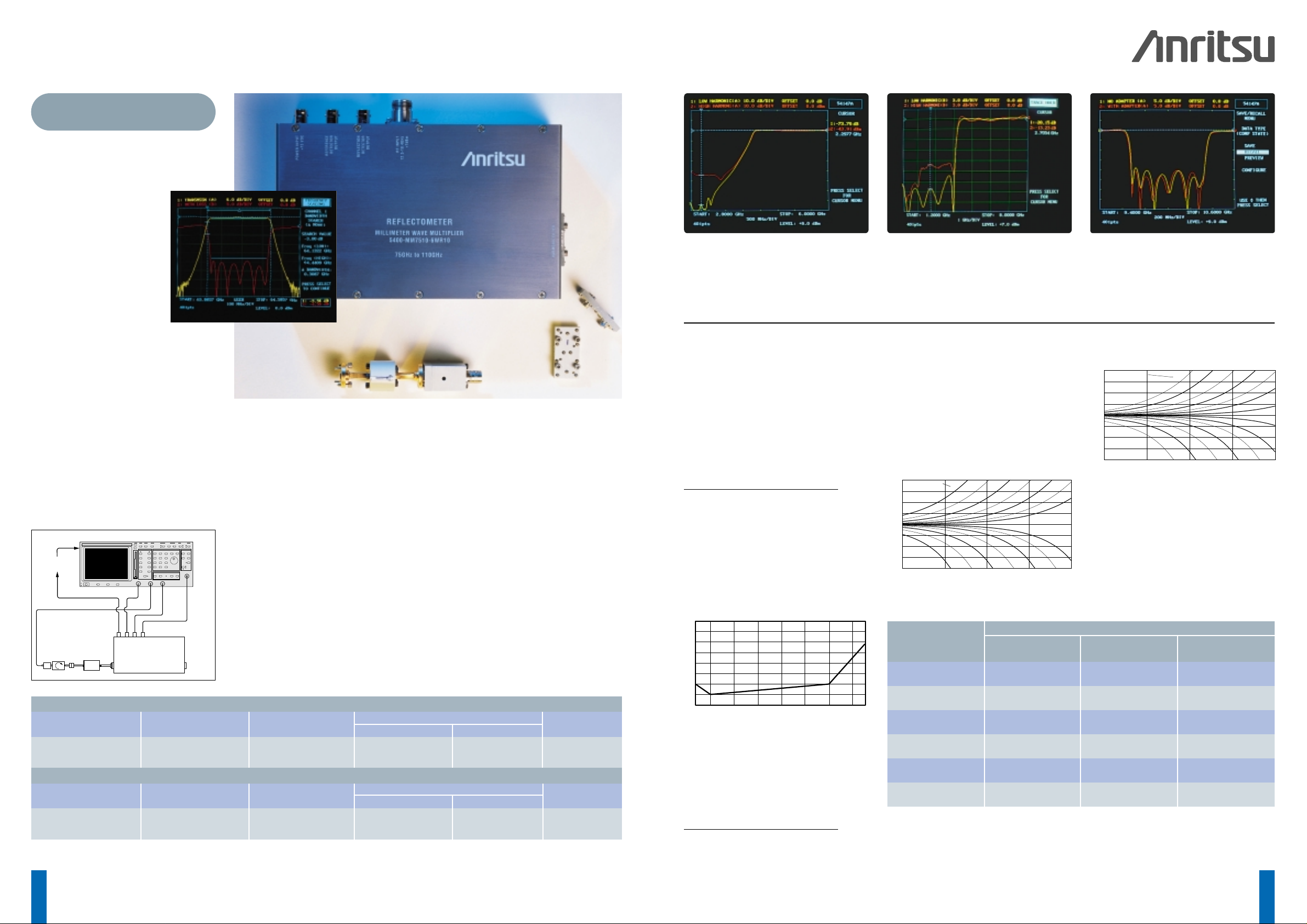
Reflection Accuracy
Characteristics
Source Match: < 1.9 (< 1.7 Typical)
Directivity: 35 dB (> 40 dB Typical)
Dynamic Range: > 56 dB
Channel Accuracy: Channel Accuracy is
degraded by ± 0.4 dB from standard 54100A
specifications
Output Power, Minimum: Leveled or
Unleveled
V-band: 0.0 dBm min. (+ 4.0 dBm Typ.)
W-band: -5.0 dBm min. (+1.0 dBm Typ.)
Power Flatness, Unleveled: ± 3.0 dB Typ.
Required Input Frequency:
V-band: 12.75 to 18.75 GHz
W-band: 12.75 GHz to 18.33 GHz
Required Input Harmonics: < -60 dBc
Spurious Signals:
Harmonic: < - 55 dBc (< -60 dBc Typical)
Nonharmonic: < -55 dBc (< -60 dBc Typical)
Frequency Accuracy: Source Dependent
Frequency Resolution: Source Dependent
Autotester accuracy is composed of error due
to directivity and error due to test port match.
Unless the DUT has very poor return loss (high
SWR), directivity will be largest source of error.
When an adapter is used at the test port, use
Effective Directivity to determine possible errors.
Note: Return loss errors due to source
harmonics will be significant when the harmonic
level is within 10 dB of the DUT’s measured
return loss.
Return Loss Accuracy Due to Directivity
Measured Return Loss Value
Millimeter Reflectometer
Accessories
12"N(m) to N(m) RF input cable:PN: N120-12
Precision Attenuators: 1.08:1.0 SWR
Precision loads and attenuators allow low
insertion loss devices such as couplers and
wavequide sections to be accurately tested.
V band 3 dB: SM4784; 6 dB, SM4786
W band 3 dB: SM4785; 6 dB, SM4787
Precision Loads: 1.06: 1.0 SWR
V band, SM4782
W band, SM4783
DC Power Connections:
SM4819 Twinax (m) - Twinax (m) cable
SM4816 Twinax to Dual Banana Plug
SM4818 Twinax to Dual EZ Hooks
Physical Characteristics
Size: 9.5 x 4.5 x 1.5 inches
Millimeter Wave Detectors
Maximum Input Power, Damage Level:
+21 dBm
Return Loss: 17 dB
System Measurement Accuracy
15
Millimeter Wave Reflectometers
14
Millimeter Wave
Measurement Systems
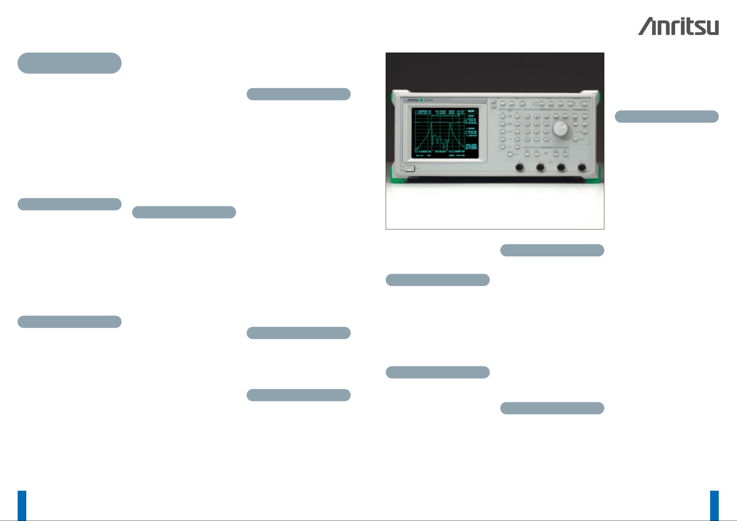
The Anritsu Millimeter Wave Reflectometers are
designed to operate with the 54100A and
56100A Scalar Measurement Systems. The
system source must cover at least to 20 GHz to
operate the millimeter wave
reflectometers. The millimeter
wave multiplier includes
subharmonic filters and an
isolator, to dramatically improve
reflection accuracy.
Excellent multiplier source
match provided by the internal
isolators and the improved
detector return loss allow
accurate, simultaneous return loss
and transmission measurements.
110 GHz Reflectometers
54000 Series Millimeter extensions with ultralow -55 dBc harmonics and > 40 dB typical
directivity provide precision measurements in
waveguide to > 110 GHz. The multiplier based
reflectometers compact a bench full of waveguide
test components into a single, rugged package.
Manufacturing and engineering benefit from
the high accuracy and low cost of Anritsu’s
millimeter wave measurement systems. The
multiplier based design offers low source
harmonics, high reliability, rugged construction,
small size, and fast setup.
The Reflectometers integrate amplifiers,
multipliers, isolation, filters, couplers, detector,
and detector matching circuits in one small
package. High quality detectors maximize two
port transmission measurement accuracy.
High Performance, Low Pricing – Anritsu’s V-band and W-band Reflectometers are designed to operate with the 54147A Scalar
Measurement System. Test port match is excellent and source harmonics are better than -55dBc.
For a typical test system the most common
causes of measurement uncertainly are:
• Excessive source harmonics
• Poor effective directivity due to test port
adapters
• Poor quality test components
Transmission Loss or Gain Measurement
Uncertainties from the frequency response of
components are automatically subtracted from
test data during the path calibration procedure.
Overall accuracy is then:
Channel Accuracy
+ Mismatch Uncertainty
+ Distortion From Source Harmonics
Transmission Measurement Accuracy
Effects of source, test device, SWR Autotester,
and detector mismatch can be significant. This
mismatch uncertainty is minimized by the
exceptionally low reflection characteristics of
Anritsu’s detectors, sources, and SWR
Autotesters. Anritsu’s ultra low source
harmonics maximize the accuracy of
measurements on filters, receivers, mixers, and
amplifiers.
Channel Accuracy (25°C):
Return Loss Measurement Accuracy
Uncertainties resulting from SWR Autotester and
source frequency response and from system
open and short characteristics are subtracted
automatically from test data.
Overall accuracy is then:
Channel Accuracy
+ Autotester Accuracy
+ Distortion From Source Harmonics
Return Loss Measurement Accuracy
The Return Loss measurement of a low pass filter is grossly
distorted when high harmonics are present. When the
source’s fundamental frequency passes 2 GHz, the second
harmonic (at 4 GHz) enters the lowpass filter’s reject band;
thus, 100% of the second harmonic power is reflected back
toward the source. Thus, the reflected harmonic power is
measured and then erroneously displayed as the return loss
characteristic between 2 and 4 GHz.
The Return Loss measurements (above) were created by the
same bandpass filter. Measurement was performed with and
without a test port adapter. Differences in the ripple display
are caused by the vector error signal of the adapter’s SWR
reflection, which alternately adds and subtracts from the
true return loss magnitude.
54000-7WR15 50 to 75 GHz > 56 dB typ. 17 dB WR-15 BNC (f)
54000-7WR10 75 to 110 GHz > 56 dB typ. 17 dB WR-10 BNC (f)
54000-6WR15 50 to 75 GHz 35 dB, 40 dB typ. <1.9 dB (<1.7 typ.) WR-15 N (f)
54000-6WR10 75 to 110 GHz 35 dB, 40 dB typ <1.9 dB (<1.7 typ.) WR-10 N (f)
Millimeter Wave Detectors
Errors due to source harmonics are most evident when
testing wide band filters. As the source’s fundamental
frequency passes 2 GHz, the -33 dBc second harmonic is at
4 GHz – within the pass band of the wideband filter.
Frequency Input
Model Range Directivity
Return Loss Flange
Connector
Special Waveguide Reflectometers Reflectometers have integrated multipliers/amplifiers. Input frequency is < 20 GHz
Frequency Input
Model Range Directivity
Return Loss Flange
Connector
Test Port
Input Port
Return Loss Accuracy Due to Source
Harmonics
Measured Return Loss Value
This chart assumes full reflections of a single
source harmonic at the DUT input. Multiple
harmonics can cause additional measurement
uncertainty. Source harmonics are a significant
source of return loss measurement uncertainty
when testing banded devices such as filters,
receivers, transmitters, power amplifiers,
and antennas.
560-97A50
560-97A50-1
560-97N50
560-97N50-1
560-97NF50
560-97NF50-1
560-98S50
560-98S50-1
560-98SF50
560-98SF50-1
560-98K50
560-98K50-1
0.016 ± 0.06Γ
2
0.016 ± 0.06Γ
2
0.018 ± 0.08Γ
2
0.013 ± 0.08Γ
2
0.018 ± 0.08Γ
2
0.013 ± 0.08Γ
2
0.014 ± 0.07Γ
2
0.010 ± 0.07Γ
2
0.014 ± 0.07Γ
2
0.010 ± 0.07Γ
2
0.018 ± 0.07Γ
2
0.016 ± 0.10Γ
2
0.010 ± 0.10Γ
2
0.018 ± 0.12Γ
2
0.013 ± 0.12Γ
2
0.018 ± 0.12Γ
2
0.013 ± 0.12Γ
2
0.014 ± 0.10Γ
2
0.010 ± 0.10Γ
2
0.014 ± 0.10Γ
2
0.010 ± 0.10Γ
2
0.018 ± 0.12Γ
2
N/A
N/A
N/A
0.016 ± 0.12Γ
2
0.013 ± 0.12Γ
2
0.016 ± 0.12Γ
2
0.013 ± 0.12Γ
2
0.025 ± 0.13Γ
2
Model
10 MHz to
8 GHz
8 GHz to
18 GHz
18 GHz to
26.5 GHz
SWR Autotester Error Terms
SWR Autotester Accuracy, Microwave:
Accuracy of Measured Reflection Coefficient (Γ) depends upon autotester directivity, test port reflection, output source SWR,
and the SWR Autotester’s insertion loss. The SWR Autotester Accuracy tables identify directivity (first term) and test port
reflection (second term) return loss accuracy contributions.
54100A NETWORK ANALYZER
(Option 16)
+15Vdc
ABR
RF IN
560-10BX-2
DETECTOR CABLE
TRANSMISSION
DETECTOR
DUT
REFLECTOMETER
MILLIMETER WAVE
TEST
5400-MMXXXX
PORT
>+5 dBm
ANRITSU
1.6
1.4
1.2
1.0
0.8
0.6
0.4
Accuracy (+/- dB)
0.2
0.0
+16 +10 0 -10 -20 -30 -40 -50 -55
Input Power (dBm)
4.00
SWR Autotester
Directivity
3.00
2.00
1.00
0.00
-1.00
-2.00
Possible Error (dB)
-3.00
-4.00
20 dB
25 dB
30 dB
35 dB
30 dB
25 dB
2
0
d
B
10 dB 20 dB 30 dB 40 dB0 dB
35 dB
40 dB
40 dB
4.00
Source Harmonic
Level
45 dB
50 dB
3.00
2.00
1.00
0.00
-1.00
-2.00
Possible Error (dB)
-3.00
-4.00
0 dB
4
5
50 dB
d
B
B
B
20 dB
-30 d
-35 dB
-35 d
-40 dB
-25 d
-30 dB
-25 d
B
10 dB
B
30 dB
-40 dB
-45 dB
-45 d
-50 dB
-60 dB
-60 dB
-50 dB
B
40 dB
 Loading...