


MODEL
360B
VECTOR NETWORK ANALYZER
OPERATION MANUAL
Software Version: 4.05
P/N: 10410-00110
REVISION: B
PRINTED: MAY 1995
COPYRIGHT 1991 WILTRON CO.
490 JARVIS DRIVE ● MORGAN HILL, CA 95037-2809

WARRANTY
The WILTRON product(s) listed on the title page is (are) warranted against defects in
materials and workmanship for one year from the date of shipment.
WILTRON’s obligation covers repairing or replacing products which prove to be
defective during the warranty period. Buyers shall prepay transportation charges for
equipment returned to WILTRON for warranty repairs. Obligation is limited to the
original purchaser. WILTRO N is not liable for consequential damages.
LIMITATION OF WARRANTY
The foregoing warranty does not apply to WILTRON connectors that have failed due to
normal wear. Also, the warranty does not apply to de fects resulting from improper or
inadequate maintenance by the Buyer, unauthorized modification or misuse, or
operation outside of the environmental specifications of the product. No other warranty
is expressed or implied, and the remedies provided herein are the Buyer’s sole and
exclusive remedies.
TRADEMARK ACKNOWLEDGEMENTS
V Connector and K Connector are registered trademarks of W ILTRON Company.
GPC-7 is a registered trademark of Amphenol Corporation.
ANACAT is a registered trademark of EEsof, Inc.
Ink Jet and Think Jet are registered trademarks of Hewlett-Packard Co.
MS-DOS is a registered trademark of Microsoft Corporation.
NOTICE
WILTRON Company has prepared this manual for use by WILTRON Company
personnel and customers as a guide for the proper installation, operation and
maintenance of WILTRON Company equipment and computer programs. The
drawings, specifications, and information contained herein are the property of
WILTRON Company, and any unauthorized use or disclosure of these drawings,
specifications, and information is prohibited; they shall not be reproduced, copied, or

MANUAL CHANGE
MANUAL:
Title: Model 360B Operation Manual
Part Number: 10410-00110
Rev. Ltr/Date: E
CHANGE PACKET
Part Number: 10900-00155
Change 1, September 1995
1. A3-1
Replace pages A3-1 and A3-2 with the enclosed like-numbered pages: Changed September 1995.
PCO 22126
360B OM C-1/C-2

MANUAL CHANGE
MANUAL:
Title: Model 360B Operation Manual
Part Number: 10410-00110
Rev. Ltr/Date: E
CHANGE PACKET
Part Number: 10900-00171
Change 2, February 1996
Conformance and Safety Pages
1.
Add the enclosed Conformance and Safety Pages to the front of the manual, between the title page and
the table of contents.
2.
Page iii
Add the enclosed the page iii/iv: Added February 1996, following page ii.
3.
Page 2-2
Replace unnumbered page 2-2 with the enclosed section title page (2-1/2-2).
4.
Page 2-12
Replace pages 2-11 and 2-12 with the enclosed like-numbered pages, Changed: February 1996
5.
Page 2-12A/2-12B
Replace page 2-12A/2-12B with the enclosed like-numbered page, Changed: February 1996
PCO 22214
360B OM C-3/C-4

MANUAL CHANGE
MANUAL:
Title: Model 360B Operation Manual
Part Number: 10410-00110
Rev. Ltr/Date: E
CHANGE PACKET
Part Number: 10900-00172
Change 3, March 1996
Title Page
1.
Replace this page with the enclosed title page/warranty page that adds “Software Version: 4.05".
2.
Page A-118
Replace pages A-117 and A-118 with the enclosed like-numbered pages Changed: March 1996.
PCO 22378
360B OM C-5/C-6

MANUAL CHANGE
MANUAL:
Title: Model 360B Operation Manual
Part Number: 10410-00110
Rev. Ltr/Date: E
CHANGE PACKET
Part Number: 10900-00184
Change 4, September 1996
1-2 (unnumbered TOC)
1.
Replace this page with the enclosed TOC pages.
Page 1-12
2.
Replace pages 1-11 and 1-12 with the enclosed like-numbered pages Changed: September 1996.
PCO 22507
360B OM C-7/C-8

MANUAL CHANGE
MANUAL:
Title: Model 360B Operation Manual
Part Number: 10410-00110
Rev. Ltr/Date: E
CHANGE PACKET
Part Number: 10900-00192
Change 5, December 1996
Declaration of Conformity page
1.
Replace this page with the enclosed Declaration of Conformity page.
1-2 (unnumbered TOC)
2.
Replace this page with the enclosed TOC page.
Page 1-14
3.
Replace pages 1-13 and 1-14 with the enclosed like-numbered pages Changed: December 1996.
Page 2-1 (unnumbered TOC)
4.
Replace this page with the enclosed TOC page.
Page 2-22
5.
Replace pages 2-21 and 2-22 with the enclosed like-numbered pages Changed: December 1996.
Page 2-25
6.
Replace pages 2-25 and 2-26 with the enclosed like-numbered pages Changed: December 1996.
PCO 22761
360B OM C-7/C-8


Safety Symbols
To prevent the risk of personal injury or loss related to equipment malfunction, WILTRON Company uses the
following symbols to indicate safety-related information. For your own safety, please read the information
carefully BEFORE operating the equipment.
Symbols used in manuals
DANGER This indicates a very dangerous procedure that could result in serious
injury or death if not performed properly.
WARNING This indicates a hazardous procedure that could result in serious in-
jury or death if not performed properly.
CAUTION This indicates a hazardous procedure or danger that could result in
light-to-severe injury, or loss related to equipment malfunction, if
proper precautions are not taken.
Safety Symbols Used on Equipment and in Manuals
(Some or all of the following five symbols may or may not be used on all WILTRON equipment. In addition,
there may be other labels attached to products that are not shown in the diagrams in this manual.)
The following safety symbols are used inside or on the equipment near operation locations to provide information about safety items and operation precautions. Ensure that you clearly understand the meanings of the
symbols and take the necessary precautions BEFORE operating the equipment.
This indicates a prohibited operation. The prohibited operation is indicated symbolically in or near the barred circle.
This indicates a compulsory safety precaution. The required operation
is indicated symbolically in or near the circle.
This indicates warning or caution. The contents are indicated symbolically in or near the triangle.
This indicates a note. The contents are described in the box.
These indicate that the marked part should be recycled.
360B OM SAFETY-1
Added: February 1996
For Safety
WARNING
When supplying power to this equipment, connect the accessory 3-pin
power cord to a 3-pin grounded power outlet. If a grounded 3-pin outlet
is not available, use a conversion adapter and ground the green wire, or
connect the frame ground on the rear panel of the equipment to ground.
If power is supplied without grounding the equipment, there is a risk of
receiving a severe or fatal electric shock.
WARNING
Repair
Changing Fuse
This equipment can not be repaired by the operator. DO NOT attempt
to remove the equipment covers or to disassemble internal components.
Only qualified service technicians with a knowledge of electrical fire
and shock hazards should service this equipment. There are high-voltage parts in this equipment presenting a risk of severe injury or fatal
electric shock to untrained personnel. In addition, there is a risk of damage to precision components.
WARNING
Before changing the fuse, AL WAYS remove the power cord from the
power outlet. There is the risk of receiving a fatal electric shock if the
fuse is replaced with the power cord connected.
Always use a new fuse of the type and rating specified by the fuse
markings on the rear panel of the instrument.
SAFETY-2 360B OM
Added: February 1996

For Safety
WARNING
Use two or more people to lift and move this equipment, or use an
equipment cart. There is a risk of back injury, if this equipment is lifted
by one person.
360B OM SAFETY-3/SAFETY-4
Added: February 1996

TABLE OF CONTENTS
Tab / Section Title
Getting Started
This separately bound, pull-out section provides a user-friendly narrative that describes how to
operate the 360B VNA. It describes the system, provides an overview of the front panel, tells how to
load the software, perform a measurement calibration, and get started making measurements.
I General Information
This section provides a general description of the WILTRON Model 360B Vector Network Analyzer
System and its major units: network analyzer, test set, and frequency source. It also provides descriptions for the precision component kits, and equipment options. Additionally, it contains the listing of
recommended test equipment.
II Installation
This section provides instructions for performing an initial inspection, preparing the equipment for
use; setting up for operation over the IEEE-488 (GPIB) Bus, using a printer; and preparing the units
for storage and/or shipment. It also provides a listing of WILTRON Customer Service Centers.
III Network Analyzers, A Primer
This section provides an introduction to network analysis and the types of measurements that can be
made using them. It provides general and introductory description.
IV Instrument Operation
This section provides an overview of the system operation. It discusses the power-up characteristics
of the system, measurement control, data enhancement, human interface, data storage, and external
and peripheral interfaces.
V Front Panel Operation
This section describes the front panel controls and provides flow diagrams for the menus called up
using the front panel controls. It contains the following subsections:
• Front Panel Control-Group Descriptions
• Calibration Keys and Indicators, Detailed Description
• Save/Recall Menu Key and Menus, Key Description and Menu Flow
• Measurement Keys and Menus, Key Descriptions and Menu Flow
• Channel Keys and Menu, Key Descriptions and Menu Flow
• Display Keys and Menus, Key Descriptions and Menu Flow
• Enhancement Keys and Menus, Key Descriptions and Menu Flow
• Output Keys and Menus, Key Descriptions and Menu Flow
• System State Keys and Menus, Key Descriptions and Menu Flow
• Markers/limits Keys and Menus, Key Descriptions and Menu Flow
• Disk Storage Interface, Detailed Description
360B OM i

Tab / Secti on Title
VI Error And Status Messages
This section describes the type of error messages you may encounter during operation and provides a
tabular listing. This listing describes and defines the error types.
VII Data Displays
This section provides a detailed description of the various data displays. It describes the graph types,
frequency markers, measurement limit lines, status displays, and data display controls.
VIII Measurement Calibration
This section provides a discussion and tutorial on measurement calibration. It contains step-by-step
calibration procedures for the Standard (OSL), Offset-Short, and LRL/LRM methods. It also has a
procedure for calibrating using a sliding termination.
IX Measurements
This section discusses measurements with the 360B VNA. It contains subsections that provide a
detailed descriptions for the following measurement types.
• Transmission and Reflection
• Low Level and Gain
• Group Delay
• Active Device
• Dual Source Control
X Options
This section describes the major measurement options. It contains subsections that provide discussion
and description for the following measurement options.
• Option 2A, Time Domain
• Option 5, Receiver Mode
A1 Appendix 1 — Front Panel Menus, Alphabetical Listing
This appendix shows all of the menus that are called up using the front panel controls. It provides a
replica of the menu and descriptive text for all of the various menu choices. The listing is alphabetical
by the menu call letters mentioned and/or illustrated in Section V.
A2 Appendix 2 — Model 360 System Rear Panel Connectors
This appendix describes the rear panel connectors for system instruments. It provides illustrations
for the network analyzer, frequency source, and test set rear panels. It also provides pinout listings
for the illustrated connectors.
A3 Appendix 3 — Performance Specifications
This appendix provides system performance specifications.
Supplements
This tab provides a repository for data sheets and other material used to supplement manual sections.
Index
ii 360B OM

WARNING
Repair
This equipment can not be repaired by the operator. DO NOT attempt
to remove the equipment covers or to disassemble internal components.
Only qualified service technicians with a knowledge of electrical fire
and shock hazards should service this equipment. There are high-voltage parts in this equipment presenting a risk of severe injury or fatal
electric shock to untrained personnel. In addition, there is a risk of damage to precision components.
360B OM iii/iv

Chapter 1
General Information
Table of Contents
1-1 SCOPE OF MANUAL . . . . . . . . . . . . . . . . . . . . . . 1-4
1-2 INTRODUCTION . . . . . . . . . . . . . . . . . . . . . . . . . 1-4
1-3 IDENTIFICATION NUMBER . . . . . . . . . . . . . . . . . . 1-4
1-4 RELATED MANUALS . . . . . . . . . . . . . . . . . . . . . . 1-4
1-5 SYSTEM DESCRIPTION . . . . . . . . . . . . . . . . . . . . 1-6
Test Set . . . . . . . . . . . . . . . . . . . . . . . . . . . . . . 1-6
Signal Source . . . . . . . . . . . . . . . . . . . . . . . . . . . 1-6
1-6 PRECISION COMPONENT KITS . . . . . . . . . . . . . . . . 1-7
Model 3650 SMA/3.5 mm Calibration Kit . . . . . . . . . . . . 1-7
Model 3651 GPC–7 Calibration Kit . . . . . . . . . . . . . . . 1-8
Model 3652 K Connector
Model 3653 Type N Calibration Kit . . . . . . . . . . . . . . . 1-9
Model 3654B
V Connector
Model 3666 3.5 mm Verification Kit . . . . . . . . . . . . . . . 1-10
Model 3667 GPC–7 Verification Kit . . . . . . . . . . . . . . . 1-10
Model 3668
K Connector
Model 3669B
V Connector
1-7 OPTIONS . . . . . . . . . . . . . . . . . . . . . . . . . . . . . 1-11
Network Analyzer . . . . . . . . . . . . . . . . . . . . . . . . . 1-11
Test Set . . . . . . . . . . . . . . . . . . . . . . . . . . . . . . 1-11
Signal Souce . . . . . . . . . . . . . . . . . . . . . . . . . . . . 1-11
Cabinets . . . . . . . . . . . . . . . . . . . . . . . . . . . . . . 1-11
1-8 FEATURES AND MISCELLANEOUS . . . . . . . . . . . . . 1-12
Test Port Converters . . . . . . . . . . . . . . . . . . . . . . . 1-12
Other . . . . . . . . . . . . . . . . . . . . . . . . . . . . . . . 1-12
® Calibration Kit . . . . . . . . . . . . . . . . . . 1-9
® Verification Kit . . . . . . . . . . . . . . . . . . 1-10
® Verification Kit . . . . . . . . . . . . . . . . . . 1-11
® Calibration Kit . . . . . . . . . . . 1-8

Extended Service Options . . . . . . . . . . . . . . . . . . . . 1-12
1-9 PERFORMANCE SPECIFICATIONS . . . . . . . . . . . . . 1-12
1-10 RECOMMENDED TEST EQUIPMENT . . . . . . . . . . . . 1-13
1-11 PREVENTIVE MAINTENANCE . . . . . . . . . . . . . . . . 1-14
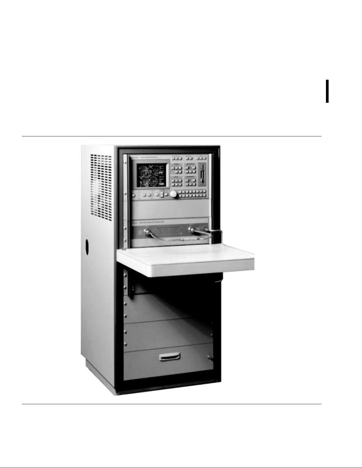
Figure 1-1. Model 360B Vector Network Analyzer System (Shown installed in Model 360C1 System Console
Replacement GPIB Cables . . . . . . . . . . . . . . . . . . . . 1-13
Accessories . . . . . . . . . . . . . . . . . . . . . . . . . . . . 1-13
On-Site Support . . . . . . . . . . . . . . . . . . . . . . . . . 1-13
Extended Service Options . . . . . . . . . . . . . . . . . . . . 1-13
1-9 PERFORMANCE SPECIFICATIONS . . . . . . . . . . . . . 1-13
1-10 RECOMMENDED TEST EQUIPMENT . . . . . . . . . . . . 1-14
Figure 1-1. Model 360B Vector Network Analyzer System (Shown installed in Model 360C1 System Console

Chapter 1
General Information
1-1
1-2
1-3
SCOPE OF MANUAL
INTRODUCTION
IDENTIFICATION NUMBER
This manual provides general information, installation, and operating
information for the Model 360B Vector Network Analyzer (VNA)
system. (Throughout this manual, the terms 360B VNA and 360B will
be used interchangeable to refer to the system.) Manual organization is
shown in the table of contents.
This section provides general information about the 360B VNA system,
which consists of the network analyzer, a test set, a signal (frequency)
source, and one or more precision-component calibration or performance verification kits. The section also provides system specifications
and a listing of recommended test equipment.
All WILTRON instruments are assigned a unique six-digit ID number,
such as “701001.” This number is affixed to a decal on the rear panel of
each unit. In any correspondence with WILTRON Customer Service,
please use this number.
NOTE
The system operating software is keyed to the analyzer
identification number. For systems having the time-domain option installed, the operating-system will only load
on the serial-numbered 360B one for which the software is
identified.
1-4
RELATED MANUALS
Manuals related to the operation and maintenance of the 360B VNA
system are listed in Table 1-1. This table also lists the 360B VNA optional equipment manuals.
360B OM 1-3

GENERAL
INFORMATION RELATED MANUALS
Table 1-1. List of Related Manuals (Continued)
Title Description Part Number
Model 360B Vector
Network Analyzer
GPIB Programming
Manual
360B GPIB
Quick Reference
Guide
Model 360B
Vector Network Analyzer Maintenance
Manual
Model 36XX Calibration and Verification
Kit Manuals
3680 S eries U ni versal T est Fixture Operation and Maintenance Manual
Model 2300-11 Materials Measurement
Software User’s
Guide
This manual provides programming
information for the 360B GPIB interface.
Alphabetically list and briefly describes all
360B GPIB commands. Provides references
to fuller command descriptions located in
360B GPIB PM. Manual is bound with the
360B GPIB PM, but can be ordered
separately.
Provides service information for the 360B
VNA.
Provides operating instructions and
maintenance information for the Models
3650, 3651, 3652, and 3653 Calibration Kits
and the Models 3666, 3667, and 3668
Verification Kits.
Provides general information, operating
instructions, calibration procedures, and
maintenance information for the 3680
Series Universal Test Fixture and optional
accessories.
Provides operating information for the
Model 360 VNA Materials Measurement
Software, WILTRON part numbers 230011A.
10410-00113
10410-00114
10410-00116
10100-00024
10410-00064
10410-00066
1-4 360B OM
GENERAL
INFORMATION SYSTEM DESCRIPTION
1-5
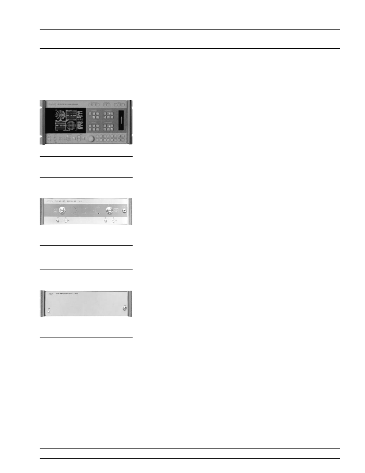
Figure 1-2. Network Analyzer
Figure 1-3. Reversing Test Set
SYSTEM DESCRIPTION
Network Analyzer
Test Set Test Sets (Figure 1-3) are available that allow micro-
Signal Source Two dedicated signal sources (Figure 1-4) are avail-
The 360B Network Analyzer (Figure 1-2) is the
control and display unit for all versions of the system. Its front panel controls provide menu selections
for test functions, test parameters, measurement enhancements, and frequencies. Frequency information is sent to the signal (frequency) source over a
dedicated system GPIB. Test parameters, system
status, and measurement data are displayed on the
large color screen and can be hard copied on a
printer or plotter.
wave vector measurements—including S-Parameter
measurements of both active and passive devices—
frequency conversion measurements, antenna
measurements, and receiver measurements. The frequency range for coaxial test sets is 40 MHz to
65 GHz. (Test Set Option 6 provides operation to
67 GHz with test set models 3613A or 3623A.) The
range for frequency converter test sets is 10 MHz to
60 GHz. The model 3535B millimeter-wave test set
provides coverage from 33 to 110 GHz.
able—10 MHz to 20 GHz and 10 MHz to 40 GHz.
Coverage to 60 or 65 GHz is provided by using a
model 360SS69 Signal Source with the appropriate
361XA/362XA coaxial test set models. (Test set models 3612/22A and 3613A/23A include a frequency tripler for operation to 65 GHz.) The signal source is
controlled by the network analyzer through a dedicated IEEE-488 bus. It provides clean, phase-locked
test signals for precise test data. Frequency resolution is 100 kHz.
WILTRON 6600B Sweep Generator models are also
compatible and can be used in place of the 360SS47
Figure 1-4. Signal Source
and 360SS69 sources.
WILTRON 67XXB Swept Frequency Synthesizer or
681XXA Synthesized Sweep Generator models are
also compatible and offer 1 kHz frequency resolution.
360B OM 1-5
GENERAL
INFORMATION PRECISION COMPONENT KITS
1-6
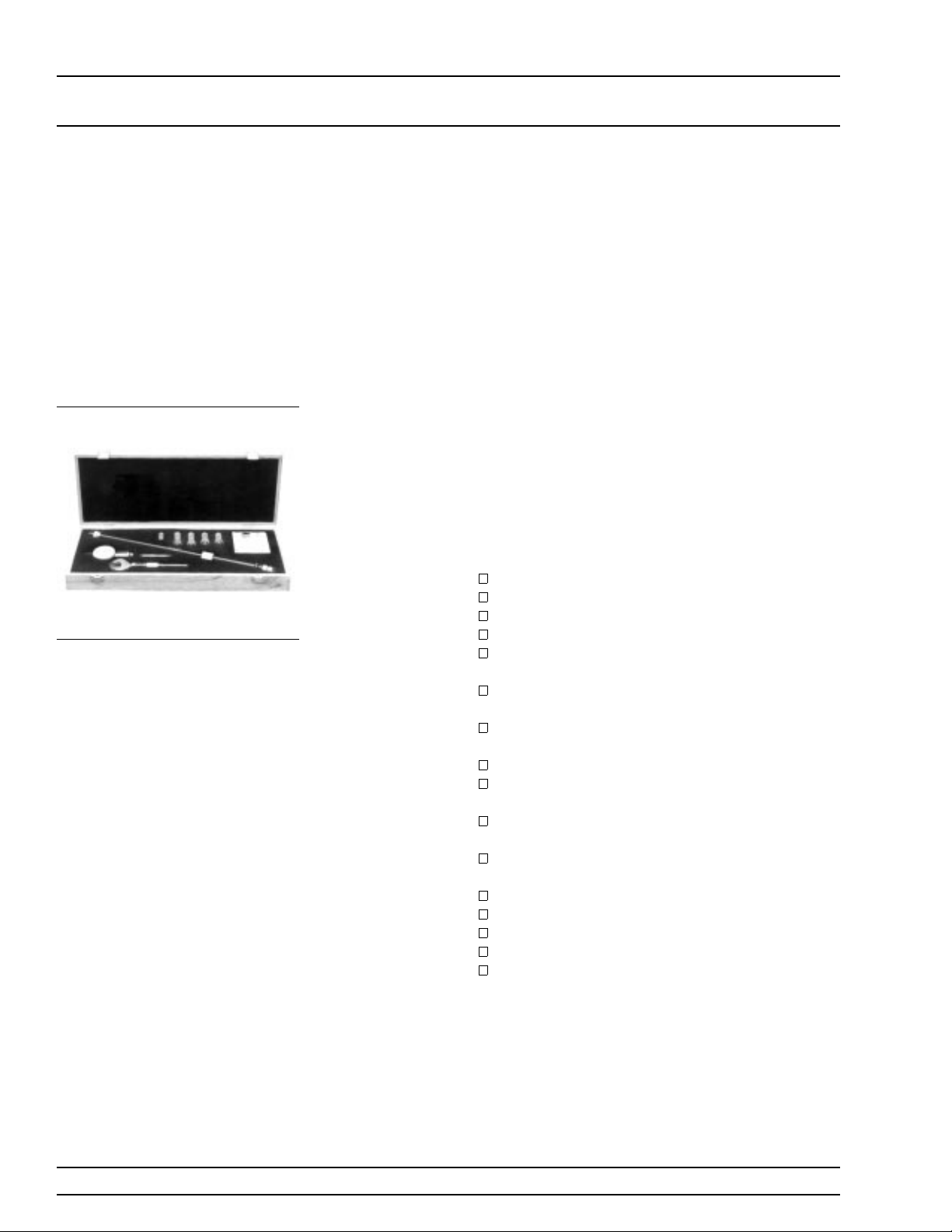
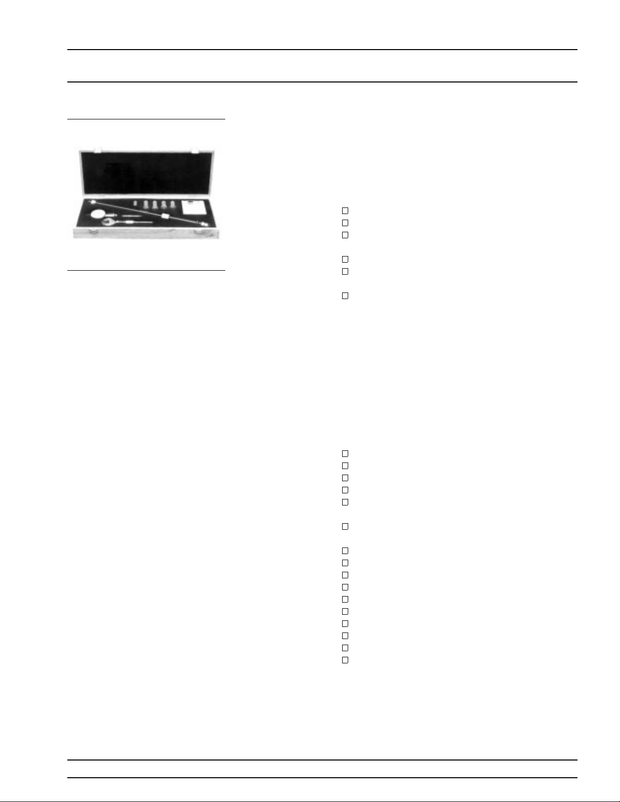
Figure 1-5. Typical Model 365X
Calibration Kit
PRECISION COMPONENT
KITS
Two types of precision-component kits are available: calibration and
verification. Calibration kits contain components used to identify and
separate error sources inherent in microwave test setups. Verification
kits consist of components with characteristics traceable to the
National Institute of Standards and Technology (NIST). This type of
kit is usually kept in the metrology laboratory where it provides the
most dependable means of checking system accuracy. Each of these
kits contains a microfloppy disk providing coefficient or measurement
data for each component. Details of these kits are described in the following paragraphs.
Model 3650
SMA/3.5 mm
Calibration
Kit
The 3650 Calibration Kit (Figure 1-5) contains all
the precision components and tools required to calibrate the 360B VNA for 12-term error-corrected
measurements of test devices with SMA or 3.5 mm
connectors. Components are included for calibrating
both male and female test ports. The kit supports
calibration with broadband loads. Option 1 adds sliding loads. Kit consists of the following components:
23S50 Short, SMA/3.5 mm Male
23SF50 Short, SMA/3.5 mm Female
24S50 Open, SMA/3.5 mm Male
24SF50 Open, SMA/3.5 mm Female
28S50–2 Termination, SMA/3.5 mm Male,
2 ea. (dc–26.5 GHz)
28SF50–2 Termination, SMA/3.5 mm Female, 2
ea. (dc–26.5 GHz)
33SFSF50 Insertable, SMA/3.5 mm Female/Female, 2 ea.
33SS50 Insertable, SMA/3.5 mm Male/Male
33SSF50 Insertable, SMA/3.5 mm Male/Female, 2 ea.
34AS50–2 Adapter, GPC–7 to SMA/3.5 mm
Male, 2 ea.
34ASF50-2 Adapter, GPC–7 to SMA/3.5 mm Female, 2 ea.
01–201 Torque Wrench
01–210 Reference Flat
01–222 Connector Gauge
01–223 Gauge Kit Adapter
Data Disk
Option 1: Adds 17S50 Sliding Load, SMA/3.5 mm
Male; 17SF50 Sliding Load, SMA/3.5 mm Female;
01–211 Female Flush Short; and 01–212 Male Flush
Short.
1-6 360B OM
GENERAL
INFORMATION PRECISION COMPONENT KITS
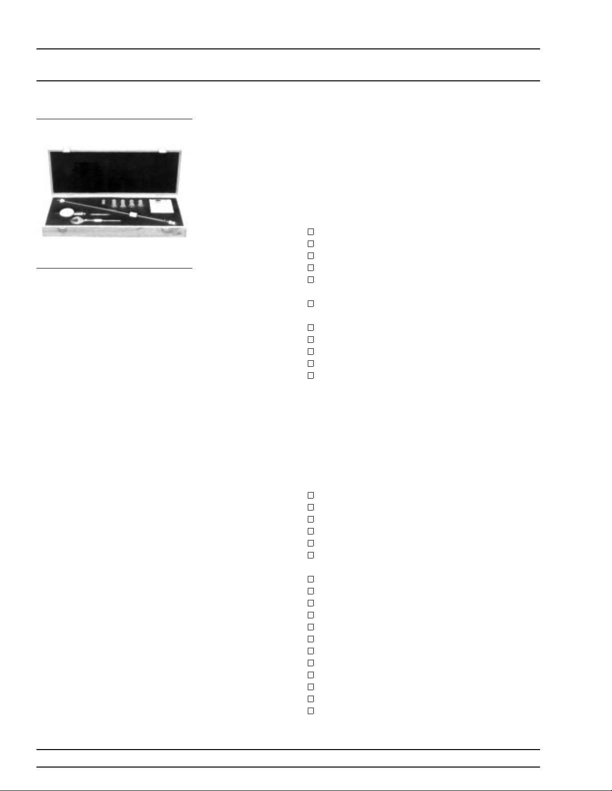
Figure 1-5. Typical Model 365X
Calibration Kit (Repeated)
Model 3651
GPC–7 Calibration Kit
Model 3652 K
Connector
Calibration
Kit
®
The 3651 Calibration Kit (Figure 1-5) contains all
the precision components and tools required to calibrate the 360B for 12-term error-corrected measurements of test devices with GPC–7 connectors. The
kit supports calibration with broadband loads. Option 1 adds a sliding load and a pin depth gauge. Kit
consists of the following components:
23A50 Short, GPC–7
24A50 Open, GPC–7
28A50–2 Termination, GPC–7, 2 ea.
(dc–18 GHz)
01–200 Torque Wrench
01–221 Collet Extractor Tool and Vial of
4 Collets
Data Disk
Option 1: Adds 17A50 Sliding Load, GPC–7; and
01–220 GPCP–7 Connector Gauge; and 01–210 Reference Flat.
The 3652 Calibration Kit (Figure 1-5) contains all
the precision components and tools required to calibrate the 360B for 12-term error-corrected measurements of test devices with K Connectors.
Components are included for calibrating both male
and female test ports. The kit supports calibration
with broadband loads. Option 1 adds sliding loads.
Kit consists of the following components:
23K50 Short, K Male
23KF50 Short, K Female
24K50 Open, K Male
24KF50 Open, K Female
28K50 Termination, K Male, 2 ea.
(dc–40 GHz)
28KF50 Termination, K Female, 2 ea.
(dc–40 GHz)
33KK50 Insertable, K Male/Male
33KFKF50 Insertable K Female/Female, 2 ea.
33KKF50 Insertable, K Male/Female, 2 ea.
34AK50 Adapter, GPC–7/K Male, 2 ea.
34AKF50 Adapter, GPC–7/K Female, 2 ea.
01–201 Torque Wrench
01–210 Reference Flat
01–222 Connector Gauge
01–223 Gauge Kit Adapter
Data Disk
Option 1: Adds 17K50 Sliding Load, K Male;
17KF50 Sliding Load, K Female; 01–211 Female
Flush Short; and 01–212 Male Flush Short.
360B OM 1-7
GENERAL
INFORMATION PRECISION COMPONENT KITS
Figure 1-5. Typical Model 365X
Calibration Kit (Repeated)
Model 3653
Type N Calibration Kit
Model 3654B
V Connector
Calibration
Kit
The 3653 Calibration Kit (Figure 1-5) contains all
the precision components and tools required to calibrate the 360B for 12-term error-corrected measurements of test devices with Type N connectors.
Components are included for calibrating both male
and female test ports. The kit supports calibration
with broadband loads. Option 1 for sliding loads is
not available in this calibration kit. Kit consists of
the following components:
23N50 Short, N Male
23NF50 Short, N Female
24N50 Open, N Male
24NF50 Open, N Female
28N50–2 Termination, N Male, 2 ea.
(dc–18 GHz)
28NF50–2 Termination, N Female, 2 ea. (dc–
18 GHz)
34AN50–2 Adapter, GPC–7/N Male, 2 ea.
34ANF50–2 Adapter, GPC–7/N Female, 2 ea.
01–213 Type N Reference Gauge
01–224 Type N Connector Gauge
Data Disk
The model 3654B Calibration Kits (Figure 1-5) con-
®
tain all the precision components and tools required
to calibrate the 360B for 12-term error-corrected
measurements of test devices with V Connectors.
This kit supports system calibration to 65 GHz. Components are included for calibrating both male and
female test ports. The kit supports calibration with
broadband loads. Kit consists of the following:
23V50B-5.1 Short, V Male
23VF50B-5.1 Short, V Female
24V50B Open, V Male
24VF50B Open, V Female
28V50B Termination, V Male, 2 ea. (dc–65 GHz)
28VF50B Termination, V Female, 2 ea.
(dc–65 GHz)
33VV50B Insertable, V Male/Male
33VFVF50B Insertable V Female/Female, 2 ea.
33VVF50B Insertable, V Male/Female, 2 ea.
01–201 Torque Wrench
01–210 Reference Flat
01–322 Connector Gauge
01–323 Gauge Kit Adapter
17V50B Sliding Load, V Male
17VF50B Sliding Load, V Female
01-311 Female Flush Short
01-312 Male Flush Short
Data Disk
1-8 360B OM
GENERAL
INFORMATION PRECISION COMPONENT KITS
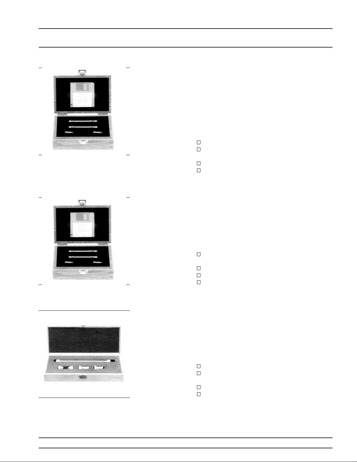
Figure 1-6. Model 3666
Verification Kit
Model 3666
3.5 mm Verification Kit
Model 3667
GPC–7 Verification Kit
The 3666 Verification Kit (Figure 1-6) contains precision 3.5 mm components with characteristics that
are traceable to the NIST. Used primarily by the metrology laboratory, these components provide the
most dependable means of determining system accuracy. A disk containing factory-measured test data
for all components is supplied for comparison with
customer-measured data.
The 3666 consists of the following components:
19S50–7 7.5 cm Air Line
19S50–7B 7.5 cm Stepped Impedance Air Line
(Beatty Standard)
42S–20 20 dB Attenuator
42S–50 50 dB Attenuator
The 3667 Verification Kit (Figure 1-7) contains precision GPC–7 components with characteristics that
are traceable to the NIST. Used primarily by the metrology laboratory, these components provide the
most dependable means of determining system accuracy. A disk containing factory-measured test data
for each component is supplied for comparison with
customer-measured data. Kit consists of the following components:
18A50–10B 10 cm Stepped Impedance Air Line
(Beatty Standard)
18A50–10 10 cm Air Line
42A–20 20 dB Attenuator
42A–50 50 dB Attenuator
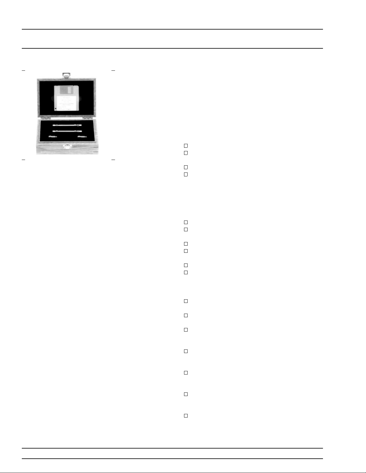
Figure 1-7. Model 3667
Verification Kit
Figure 1-8. Model 3668
Verification Kit
Model 3668
K Connector
Verification
Kit
The 3668 Verification Kit (Figure 1-8) contains preci-
®
sion K Connector components with characteristics
that are traceable to the NIST. Used primarily by
the metrology laboratory, these components provide
the most dependable means of determining system
accuracy. A disk containing factory-measured test
data for each component is supplied for comparison
with customer-measured data. Kit consists of the following components:
19K50–7 7.5 cm Air Line
19K50–7B 7.5 cm Stepped Impedance Air Line
(Beatty Standard)
42K–20 20 dB Attenuator
42K–50 50 dB Attenuator
360B OM 1-9
GENERAL
INFORMATION OPTIONS
Figure 1-9. Model 3669
Verification Kit
1-7
OPTIONS
Model 3669B
V Connector
Verification
Kit
The following options are available.
Network
Analyzer
The 3669B Verification Kits (Figure 1-9) contain pre-
®
cision V Connector components with characteristics
that are traceable to the NIST. Model 3669B supports verification to 65 GHz .Used primarily by the
metrology laboratory, these components provide the
most dependable means of determining system accuracy. A disk containing factory-measured test data
for each component is supplied for comparison with
customer-measured data. Kit consists of the following components:
19V50–5 5 cm Air Line
19V50–5B 5 cm Stepped Impedance Air Line
(Beatty Standard)
42V–20 20 dB Attenuator
42V–40 40 dB Attenuator
Option 1: Rack Mount Slides and Ears.
Option 2A: High Speed Time (Distance) Domain Measurement Capability.
Option 5: Receiver Mode Capability
Option 102A: Field upgrade of Option 2A.
Test Set
Signal Source
Cabinets
Option 1: Rack Mount Slides and Ears.
Option 3: Assymetrical configuration, optimizes
dynamic range and performance for the forward parameters. (Not available for 3630A and
3631A Test Sets)
Option 4: 10 MHz Frequency Coverage (Available only for 3630A and 3631A Test Sets)
Option 5: 62.5 GHz Frequency Coverage (Available only for 3612A and 3622A Test Sets)
Option 6: 67 GHz Frequency Coverage (Available only for 3613A and 3623A Test Sets)
Option 1: Rack Mount Slides and Ears.
360C1 System Console, including a work shelf,
support rails, component storage drawer, and
power distribution.
360C2 System Cabinet, including support rails,
component storage drawer and power distribution.
360C3 Millimeter-Wave System Console.
1-10 360B OM

GENERAL
INFORMATION FEATURES AND MISCELLANEOUS
1-8
FEATURES AND
MISCELLANE OUS
Test Port
Cables
Test Port
Converters
3670A50–1 Test Port Cable, dc to 18 GHz,
GPC–7 connectors, 1 foot long, 2 each required.
3670A50–2 Test Port Cable, dc to 18 GHz,
GPC–7 connectors, 2 feet long.
3670K50–1 Test Port Cable, dc to 40 GHz, K
Connectors, 1 foot long, male/female, 2 each re-
quired.
3670K50–2 Test Port Cable, dc to 40 GHz, K
Connectors, 2 feet long, male/female.
3670V50–1 Test Port Cable, dc to 60 GHz, V
Connectors, 1 foot long, male/female, 2 each re-
quired.
3670V50–2 Test Port Cable, dc to 60 GHz, V
Connectors, 2 feet long, male/female.
Test port converters are available for use with the
3610A, 3611A, 3620A, and 3621A Test Sets.
34UA50 Test Port Adapter,
Universal/GPC–7
34UK50 Test Port Adapter,
Universal/K Connector, male.
34UN50 Test Port Adapter,
Universal/N male.
34UNF50 Test Port Adapter,
Universal/N female.
34UQ50 Test Port Adapter,
Universal/2.4mm male.
34US50 Test Port Adapter,
Universal/APC-3.5
Test port converters for 3612A and 3622A Test Set
34YA50 Test Port Adapter, Universal/
GPC–7
34YK50 Test Port Adapter, Universal/
K Connector, male.
34YQ50 Test Port Adapter, Universal/2.4mm
male.
34YSS50 Test Port Adapter, Universal/SSMA
male.
34YV50 Test Port Adapter, Universal/V male.
Other
01-202 Wrench, for changing test set Test Port
Converters.
2300-10 ANACAT Software.
2300-11A Material Measurement Software
2300-13 Lab Windows® Software
2300-14 360/360B Instrument Driver for Lab
Windows
®
360B OM 1-11

GENERAL
INFORMATION PERFORMANCE SPECIFICATIONS
1-9
PERFORMANCE
SPECIFICATIONS
Replacement
GPIB Cables
Accessories
On-Site
Support
Extended
Service Options
System performance specifications are provided in Appendix 3.
2100-1 GPIB Cable, 1m (3.3 ft.)
2100-2 GPIB Cable, 2m (6.6 ft.)
2100-4 GPIB Cable, 4m (13.2 ft.)
2100-5 GPIB Cable, 0.5m (1.65 ft.)
2225C Ink Jet Dot-Matrix Printer.
2225-1 Spare Printer Interface Cable.
2225-2 Replacement Ink Jet Cartridges.
2225-3 Fan-Fold Ink Jet Printer Paper
(500 sheets).
2000-209 3.5-inch Blank Diskettes (Box of 10)..
360MS Option 11: On-Site Verification.
360MS Option 12: On-Site Service.
Additional, one year and two year “return to WILTRON” service is available. Prices and details are
available from your WILTRON Sales Representative
or by contacting the factory.
1-12 360B OM
Changed: September 1996

GENERAL
INFORMATION RECOMMENDED TEST EQUIPMENT
1-10
RECOMMENDED TEST
EQUIPMENT
Table 1-2 lists the recommended test equipment for maintaining and
servicing the 360B VNA system.
Instrument Critical Specification Recommended Manufacturer/Model
Spectrum
Analyzer,
with
Diplexer and
External Mixers
Power Meter,
with
Power Sensors
Digital Multimeter
Frequency
Counter,
with
External Mixers
Frequency:
Resolution:
Range:
µW to 100 mW)
(1
Other:
Resolution:
DC Accuracy:
counts
DC Input Z:
AC Accuracy:
counts (to 20 kHz)
AC Input Z:
Range:
Input Z: 50
Resolution:
Other:
Input
0.01 to 60 GHz
10 Hz
–30 to +20 dBm
GPIB-controllable
4-1/2 digits
0.002% +2
10 MΩ
0.07% +100
1 MΩ
0.01 to 60 GHz
Ω
1 Hz
External Time Base
Tektronix, Inc. Model 494P,with
External Mixers:
WM 490K (18 to 26.5 GHz)
WM 490A (26.5 to 40 GHz)
WM 490U (40 to 60 GHz)
WM 490V (50 to 75 GHz)
Diplexer PN: 015-0385-00
Hewlett-Packard Model 437B, with
Option 22 (GPIB), and
Power Sensors:
HP 8485A (0.05 to 26.5 GHz)
HP 8487A (0.05 to 50 GHz)
John Fluke, Inc. Model 8840A, with
Option 8840A-09 (True RMS AC)
EIP Microwave, Inc. Model 578A, with
External Mixers:
Option 91 (26.5 to 40 GHz)
Option 92 (40 to 60 GHz)
Option 93 (60 to 90 GHz)
Oscilloscope
Function
Generator
Bandwidth:
Vertical Sensitivity:
division
Horiz Sensitivity:
division
DC to 150 MHz
2 mV/
50 ns/
Output Voltage Range:
300 mV to 10V
Functions:
200 Hz Sine Wave
100 Hz Square Wave
Tektronix, Inc. Model 2445
Hewlett-Packard Model 3325A
360B OM 1-13

GENERAL
INFORMATION PREVENTIVE MAINTENANCE
1-11
PREVENTIVE
MAINTENANCE
Cleaning of the rear panel fan filters is the only preventive maintenance that is required on the 360B VNA System (Analyzer, Test Set,
Signal Source). These filters should be inspected montly and cleaned
when necessary. To clean:
Step 1. Turn power off on the 360B, using the POWER key.
Step 2. Remove the four thumbscrews securing the fan guard and
remove the fan filter.
Step 3. Clean the filter using warm water and a mild detergent.
Step 4. Reinstall the filter and fan guard.
Step 5. Restore the power and verify that the fan is operational.
1-14 360B OM
Changed: December 1996

Chapter 2
Installation
Table of Contents
2-1 INTRODUCTION . . . . . . . . . . . . . . . . . . . . . . . . . 2-3
2-2 CONFIGURATIONS . . . . . . . . . . . . . . . . . . . . . . . 2-3
2-3 INITIAL INSPECTION . . . . . . . . . . . . . . . . . . . . . 2-3
2-4 PREPARATION FOR USE, 360C1 CONSOLE . . . . . . . . . 2-3
2-5 EQUIPMENT INTERCONNECTIONS . . . . . . . . . . . . . 2-10
2-6 PREPARATION FOR USE, 360C2 CABINET . . . . . . . . . 2-12
2-7 PREPARATION FOR USE, 360C3 CONSOLE . . . . . . . . . 2-16
2-8 CHANGING THE LINE VOLTAGE . . . . . . . . . . . . . . . 2-22
Network Analyzer . . . . . . . . . . . . . . . . . . . . . . . . . 2-22
Frequency Source . . . . . . . . . . . . . . . . . . . . . . . . . 2-22
2-9 GPIB SETUP AND INTERCONNECTION . . . . . . . . . . . 2-23
Interface Connector . . . . . . . . . . . . . . . . . . . . . . . . 2-23
Cable Length Restrictions . . . . . . . . . . . . . . . . . . . . 2-23
GPIB Interconnection . . . . . . . . . . . . . . . . . . . . . . 2-23
GPIB Address . . . . . . . . . . . . . . . . . . . . . . . . . . 2-24
Data Delimiting (CR-CR/LF Switch) . . . . . . . . . . . . . . . 2-24
2-10 PRINTER SETUP AND INTERCONNECTION . . . . . . . . 2-24
2-11 PREPARATION FOR STORAGE/SHIPMENT . . . . . . . . . 2-24
Preparation for Storage . . . . . . . . . . . . . . . . . . . . . . 2-24
Preparation for Shipment . . . . . . . . . . . . . . . . . . . . 2-24
2-12 RACK MOUNT INSTALLATION (OPTION 1) . . . . . . . . . 2-25
 Loading...