

Annovi Reverberi HIGH PRESSURE PISTON PUMPS User Manual
MEMBER OF
CPA
cleaning power association
OPERATING INSTRUCTIONS AND
MAINTENANCE MANUAL FOR HIGH
PRESSURE PISTON PUMPS
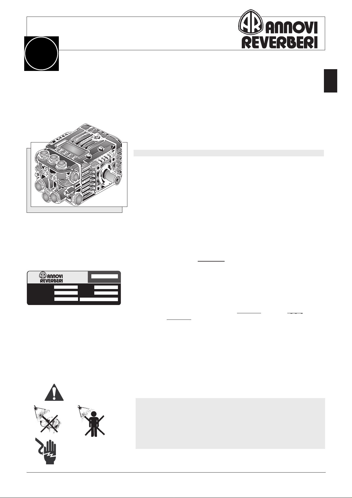
Fig.1a- A&R pump XT 8.14N - Dx (RHS)
INDEX
Page
General technical features of high pressure pumps 1
AFETY STANDARDS 1
S
Installation 2
Input water supply 2
Before starting up 2
During running 3
Switching off and storing precautions 3
Trouble shooting 3
Maintenance standards 4 ÷ 6
Gearbox assembly XT - XR 6
Charts 8
page
1
VOLUME
PRESS.
R.P.M.
Fig.2a- Nameplate
8 L/min
140 bar
1450
ATTENTION
GENERAL TECHNICAL FEATURES OF HIGH PRESSURE PUMPS
The range of A/R plunger pumps is used with flows from 8 to 40 Litres/min.
(2.1 to 11 gpm) and with maximum pressures of 250 bar ( 3600 PSI). Each
type of pump is designed and developed to work at the performance
indicated on the pumps
nameplate.
If, infact, the flows depends upon:
a) the diameter of the piston,
b) the stroke of the piston,
c) the number of pistons,
d) the number of stokes for minute;
kW
HP
XT 8.14
2,2
3
the pressure generated by the pump depends upon the choice of the nozzle,
IT IS THEREFORE A NECESSITY THAT THE PRESSURE AND THE R.P.M. REMAIN
WITHIN
THE MAXIMUM VALUES INDICATED.
The pumps are made of special materials, which are resistant to corrosion
such as stainless steel, ceramic compounds, brass and aluminium alloys
with protective treatments.
Ceramic pistons, moving parts in an oil bath, oil level dipstick and oil level
window for quick check. High quality packings with easy access, making
for rapid maintenance, as well as inspection friendly suction/outlet valves.
The hydraulics are separated from the crank mechanism with a recovery
and recycling system for leaks, thereby avoiding the pollution of the
lubricating oil.
SAFETY STANDARDS
• Do not spray persons or animals with a high pressure jet.
• If driven by an electric motor, the machine must be equipped with a
protective circuit which guarantees the operator's safety from high
voltage.
•If driven by a gas engine, do not use the unit indoors. Discharge gases
include carbon monocide an odourless but lethal gas.
ANNOVI & REVERBERI S.p.A. - 41100 Modena (Italy)
Via Martin Luther King,3 - Zona Industriale Torrazzi
Tel. 059/25.10.57 - Telex 511314 AR-I - Telefax 059/25.35.05

INSTALLATION
page
2
Outlet
LHS
➦
O
Inlet
Fig.1b- The pump can rotate either in
clockwise or anticlockwise direction.
RHS
The pump must be installed horizontally, blocked in a stable manner, by
means of the coupling flanges suitable for the type of motor/engine with
which the pump will be driven. If pulley drive is used, you must have a
protection guard.
.The pumps can rotate either clockwise or anticlockwise.
Suction and outlet piping can be attached either to the left hand side or right
hand side of the pump.
The suction hose must:
- be of a diameter equal to from 1 to 1.5 times the suction part of the pump,
- set up in such a way as to avoid the forming of air pockets,
- be as short as possible and hermetically attached to the pump to avoid
sucking air.
Below please find an example of a correct installation:
Pump
Outlet
Filter
OUTOUT
OUT
OUTOUT
ININ
IN
ININ
Pressure
gauge
⇑
Inlet
MINIMATIC / ZEROMATIC 83
GYMATIC / COMBISET
Gun Nozzle
By-pass
High pressure
hose
Filter mod.FAS
COD.3000, max 20L/min
38 MESH
Fig.4b- Check the suction filter
periodically.
Fig.5b- Replace the
RED cap with the
dipstick supplied
with the pump.
Fig.2b- Installation schematic with pressure regulating valve
INPUT WATER SUPPLY
Utilize liquids free from impurities (such as sand or other solid particles
which will affect the efficiency of the valves, the piston and the packings).
For this reason it is advisable to fit a filter on the suction hose, with a large
filtering surface and low load loss. Replace the filter as soon as it becomes
clogged up, to avoid noisy operation and pulsations which can damage the
mechanical parts of the pump. If the pump draws from a tank place the filter
at the entrance of the same.
NB: Maximum temperature of pumped liquid is 60°C (140°F),
maximum forced suction (measured at the pump) is
10 bar (145
PSI).
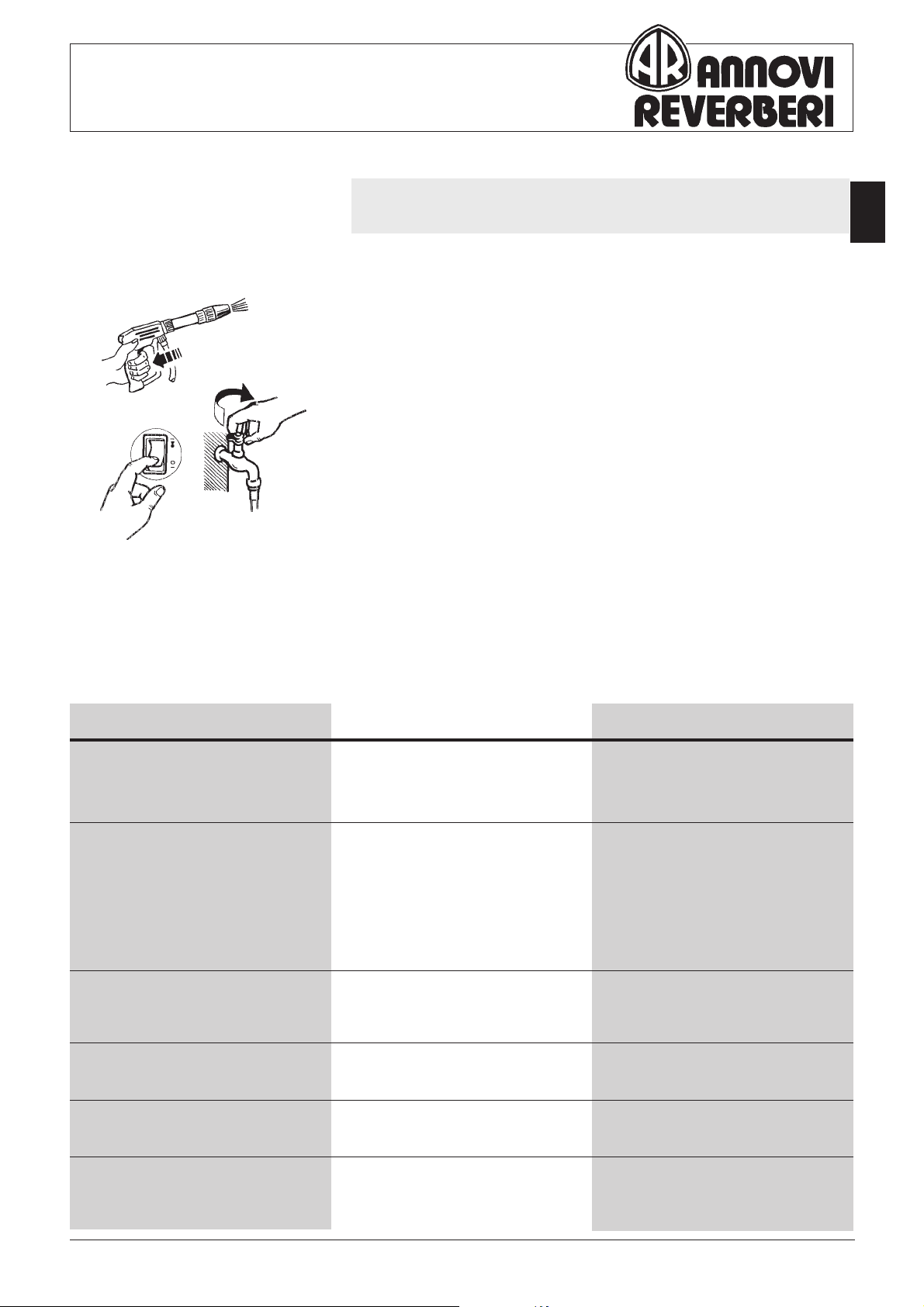
BEFORE STARTING UP
1. The pump is supplied complete with oil, so the first thing to do is remove
the red cap utilized for transportation, and insert the dipstick which is
supplied with the pump.
2. Check that oil is at the correct level, by means of the oil level window
topping up if necessary using oil type indicated in chart 1.1 page 8.
3. Make sure that inlet water flow is sufficient-at least the same value as the
pump flow and that it comes out without air bubbles.
4. Prime the pump with the outlet completely open.
5. Then start up the motor, if using a gas engine bring the RPM 's up to pre-
set level.
DURING RUNNING
1
1
2
2
Check the efficiency of the hydraulic circuit whilst pump is running: drips
or signs of wear on the hoses can cause injuries as well as prejudicate the
life and performance of the machine.
If the circuit recycles by means of a by-pass, avoid running the pump for
long periods of time without pulling the trigger since this heats the liquid
up and could damage the seals.
TURNING OFF AND STORING PRECAUTIONS
1. Pull the trigger whilst turning off the machine, to make sure no high
pressure spraying is possible.
2. Turn off the motor.
3. Turn off inlet liquid supply.
TORING
S
3
3
If the pump is not used for more than 30 days, proceed as follows:
- empty it of all pumped liquid, taking care to do the same with all pipings
and accessories,
- clean it by removing any calcareous deposits,
- wrap up in a protective cover,
- store in a clean and dry place, protected from frost.
page
3
PROBLEM CAUSE REMEDY
The pump doesn't reach required pressure
The pump is noisy
Pressure gauge fluctuates
Water leaks from the bottom of the
pump
Water leaks from head
Oil leaks from the bottom of the pump
TROUBLE SHOOTING
Unsuitable or worn out nozzle
Reg. valve seat worn out
Pump sucking air
Valves blocked by foreign bodies, or
worn
Packing worn
High temperature of pumped liquid
Piston packing worn
Head O-Ring worn
Oil seals worn
Replace nozzle
Replace valve seat
Check suction manifold
Clean or replace valves
Replace packing
Reduce temperature of pumped liquid
Replace piston packing
Replace O-Ring
Replace seals
Over pressure when gun is closed
Leaking in unloader valve and incorrect setting
Control the valve and set new pressure
level
 Loading...