


6000i
Table of contents
 Loading...
www.anilam.com
6000M
CNC Setup Utility
Manual

CNC Setup Utility Manual
P/N 70000490C - Warranty
All rights reserved. Subject to change without notice. iii
10-December-04
Warranty
ANILAM warrants its products to be free from defects in material and workmanship for one (1)
year from date of installation. At our option, we will repair or replace any defective product upon
prepaid return to our factory.
This warranty applies to all products when used in a normal industrial environment. Any
unauthorized tampering, misuse or neglect will make this warranty null and void.
Under no circumstances will ANILAM, any affiliate, or related company assume any liability for
loss of use or for any direct or consequential damages.
The foregoing warranties are in lieu of all other warranties expressed or implied, including, but
not limited to, the implied warranties of merchantability and fitness for a particular purpose.
The information in this manual has been thoroughly reviewed and is believed to be accurate.
ANILAM reserves the right to make changes to improve reliability, function, or design without
notice. ANILAM assumes no liability arising out of the application or use of the product
described herein.
Copyright 2004 ACU-RITE COMPANIES, Inc.

CNC Setup Utility Manual
P/N 70000490C -Table of Contents
All rights reserved. Subject to change without notice. v
10-December-04
Section 1 - Setup Utility Concepts
Introduction ......................................................................................................................................1-1
Effectivity Notation........................................................................................................................ 1-1
Software Version Information ....................................................................................................... 1-1
Navigating Through the Setup Utility................................................................................................ 1-2
Default Settings ............................................................................................................................1-2
Keypad Keys ................................................................................................................................ 1-2
Axis Keys...................................................................................................................................... 1-3
Console Switches/Manual Panel Keys ......................................................................................... 1-3
ENTER Key .................................................................................................................................... 1-4
Highlighting Menu Options ........................................................................................................... 1-4
Exiting a Screen ........................................................................................................................... 1-4
Password Restricted Parameters ................................................................................................. 1-4
Changing Protected Parameters......................................................................................1-5
Saving Changes to Setup Parameters .............................................................................................1-5
Setting Parameters in Setup Utility................................................................................................... 1-5
Using Valid Parameter Ranges ........................................................................................................ 1-6
Accessing Setup Utility..................................................................................................................... 1-6
Units of Measurement ......................................................................................................................1-6
Section 2 - Machine Constants
Machine Constants Group Assignments .......................................................................................... 2-1
Machine Constants Setup ................................................................................................................2-2
Control Software Parameters ......................................................................................................... 2-71
Compensation Cutoff.................................................................................................................. 2-71
User Definable Variables................................................................................................................ 2-73
Program Directory Parameters....................................................................................................... 2-73
RS-232 Communication Parameters.............................................................................................. 2-73
Encoder Resolution Examples ....................................................................................................... 2-73
Axes Parameters............................................................................................................................ 2-74
Setting the Display Resolution.................................................................................................... 2-74
Setting In-Position Tolerance ......................................................................................................... 2-75
Setting Default Rapid Rate.............................................................................................................2-76
Spindle Parameters........................................................................................................................ 2-76
Setting Spindle Gear Ranges .....................................................................................................2-77
Ballscrew Compensation Parameters ............................................................................................2-78
Automatic File Loader................................................................................................................. 2-78
Laser File Data File Format ........................................................................................................ 2-80
Generating Ballscrew Compensation Values from Laser Files ......................................2-81
File Loader Error Messages...........................................................................................2-82
Software Limits Setup Parameters................................................................................................. 2-83
Setting Software Limits............................................................................................................... 2-83
Direct Numeric Control Setup Parameters ..................................................................................... 2-84
Selecting a DNC Execution Mode .............................................................................................. 2-84
Setting the Buffer Size................................................................................................................2-84
Setting Wait For Start Before Execution ..................................................................................... 2-85
Miscellaneous Setup Parameters................................................................................................... 2-85
Linear and Rotary Axis Dry Run Feedrate.................................................................................. 2-85
M-Code for Macro Call and Macro Called for M-Code ...................................................................2-86
Tool Management .......................................................................................................................... 2-86
Activation Options....................................................................................................................... 2-86
Manual Tool Change Operation.................................................................................................. 2-87
Automatic Tool Change Operation .............................................................................................2-88

CNC Setup Utility Manual
P/N 70000490C -Table of Contents
vi All rights reserved. Subject to change without notice.
10-December-04
Enabling M19 Commands ..........................................................................................................2-90
Guidelines for Setting the Number of Digits for T-Words............................................................ 2-90
Guidelines for Setting Tool Change Macro Parameters ............................................................. 2-91
Tool Changer Macro Example.................................................................................................... 2-91
Section 3 - Other Setup Options
Builder Messages............................................................................................................................. 3-1
Enabling Builder Messages ..........................................................................................................3-2
Editing Error Messages ................................................................................................................ 3-2
Editing Warning Messages........................................................................................................... 3-3
Programmable I/O Interface Setup................................................................................................... 3-3
Display Settings ...............................................................................................................................3-3
Software Updates............................................................................................................................. 3-4
Security ............................................................................................................................................3-4
Section 4 - Configuration Utilities
Save Configuration........................................................................................................................... 4-1
Copy Configuration........................................................................................................................... 4-1
Restore from Copy ........................................................................................................................... 4-2
Restore from Backup ....................................................................................................................... 4-2
Compare Configuration .................................................................................................................... 4-2
Print Configuration ...........................................................................................................................4-3
Section 5 - Tuning the Current, Velocity, and Position Controller
Tuning Modes ..................................................................................................................................5-1
Automatic Tuning ............................................................................................................................. 5-1
Current Controller Auto-tuning Test.............................................................................................. 5-2
Frequency Auto-tuning Test ......................................................................................................... 5-4
Velocity Controller Auto-tuning Test ............................................................................................. 5-5
Guidelines to Fine-Tune the Velocity Controller ...........................................................................5-7
Position Controller Auto-tuning Test ............................................................................................. 5-8
Manual Tuning ...............................................................................................................................5-10
Current Tune – Manual Test....................................................................................................... 5-10
Frequency Tune – Manual Test.................................................................................................. 5-11
Velocity Proportional – Manual Tuning Test ............................................................................... 5-12
Velocity Integral – Manual Tuning Test ...................................................................................... 5-12
Position Proportional – Manual Tuning Test............................................................................... 5-12
Acceleration Feedforward – Manual Tuning Test ....................................................................... 5-12
Miscellaneous Tests....................................................................................................................... 5-13
Current vs. Distance Plot............................................................................................................ 5-13
Overall System Performance......................................................................................................5-14
I/O Monitor.................................................................................................................................. 5-15
Section 6 - Setup Utility Maps
Map 1 ...............................................................................................................................................6-2
Map 2 ...............................................................................................................................................6-3
Index ..................................................................................................................................... Index-1

CNC Setup Utility Manual
P/N 70000490C - Setup Utility Concepts
All rights reserved. Subject to change without notice.
10-December-04
1-1
Section 1 - Setup Utility Concepts
Introduction
The Setup Utility is used to configure the Computer Numerical Control
(CNC) and optimize the system. The machine builder performs most of
the initial machine setup at the time of the installation. This manual
documents all parameters and the procedure to change them. All
changes are made using the Setup Utility. The parameter settings are
saved in a configuration file in the CNC’s memory. The name of the
configuration file is P6MCFG.CFG.
Effectivity Notation
Some sections of this manual apply only to specific ANILAM CNC
product(s). In these sections, icons in the left margin identify the
product(s) to which the information applies. Table 1-1 lists the icons for
each CNC product and the number of axes supported by each product.
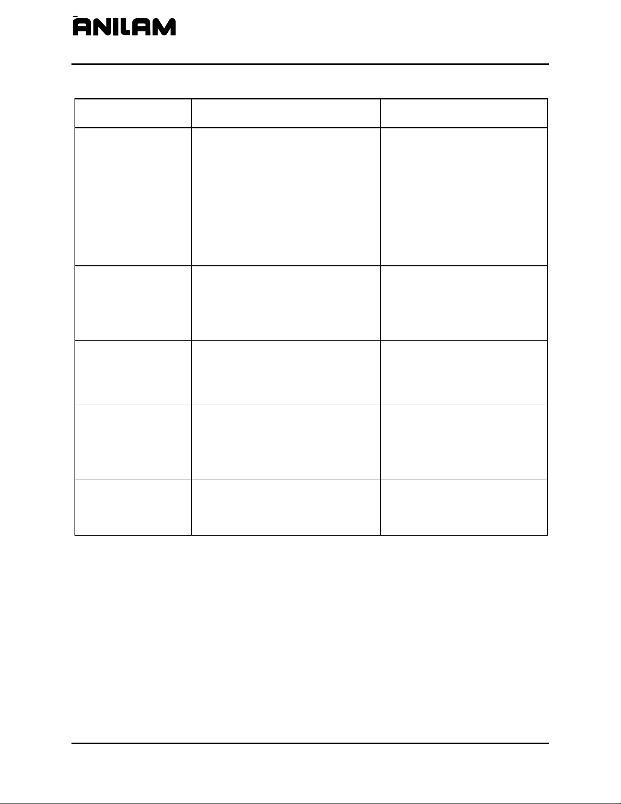
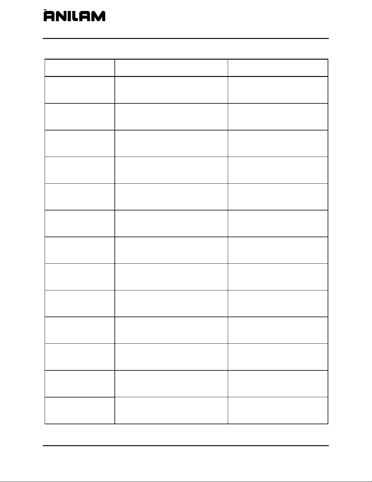
Table 1-1, CNC Effectivity Icon Description
Icon Product Axes Supported
6300M
6000M-3X Systems 3
6400M
6000M-4X Systems 4
NOTE: All systems also support one spindle axis.
The main difference between the products is the number of axes
supported. Generally, this manual describes the 6000M-3X systems.
The 6000M-4X operates exactly as the 6000M-3X system except for
features that include the additional axes.
There are many parameters that are defined per axis. In these cases,
this manual will document the primary axes (that is, XYZ). The
parameters for the auxiliary axis (that is, U) are entered in the same way
as those for the primary axes. Some parameters can also be specified
for the Spindle axis (that is, S).
Software Version Information
To facilitate verification of software version information, a text file is added
to all CNC machine and offline software disks. The file lists the version
and the CNC type. The software version contained on the disk is coded
into the filename using the following format
: 0xxxx.txt. For example,
software version 4.14A is formatted as
0414A.txt. Therefore, a disk
containing software version
4.14A contains a file named 0414A.txt.
6000M-3X
6000M-4X
CNC Setup Utility Manual
P/N 70000490C - Setup Utility Concepts
All rights reserved. Subject to change without notice.
10-December-04
1-2
Navigating Through the Setup Utility
The Setup Utility provides access to parameter settings through menus
and submenus. Each menu contains a list and a highlight. Highlight one
of the choices listed. Press
ENTER to activate the highlighted choice.
Each menu provides access to parameter settings or another menu.
Press
ENTER to toggle settings On or Off. Type a specific value where
required. Press
ENTER or Exit (F10) to save settings when prompted by
the software. Press Exit (F10) to close a menu and return to the previous
menu.
Refer to “Section 6 - Setup Utility Maps
” for all maps referenced in
“Sections 1 – 4.” Use these maps to locate parameter settings. The
maps also serve as a quick reference guide.
NOTE: All dimensions, numbers, assigned values, and defaults
provided in this manual are subject to change without notice
depending upon individual manufacturing considerations and
industry standards.
Default Settings
The Setup Utility has default settings pre-loaded in the configuration file.
These settings remain active unless you change them. In this manual,
default settings are specified as: [Default: Setting].
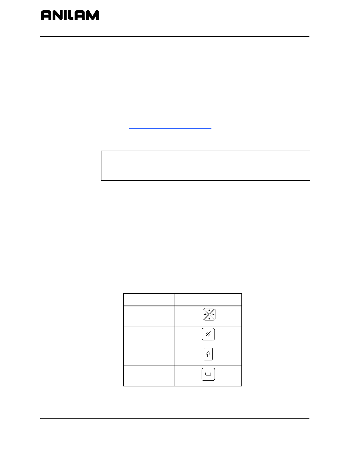
Keypad Keys
In this manual, the names ARROWS, CLEAR, SHIFT, and SPACE are
used for the corresponding keypad keys. See Table 1-2 for their
identifying key faces.
Additionally, the alphanumeric characters, (A – Z) and (0 – 9), are used to
reference corresponding alphanumeric keys.
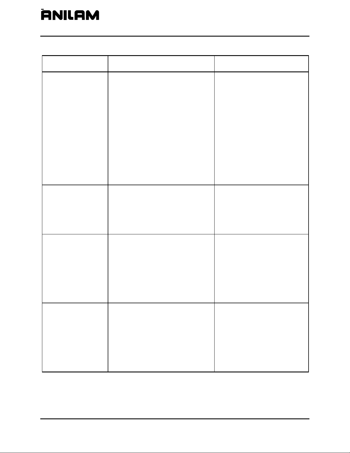
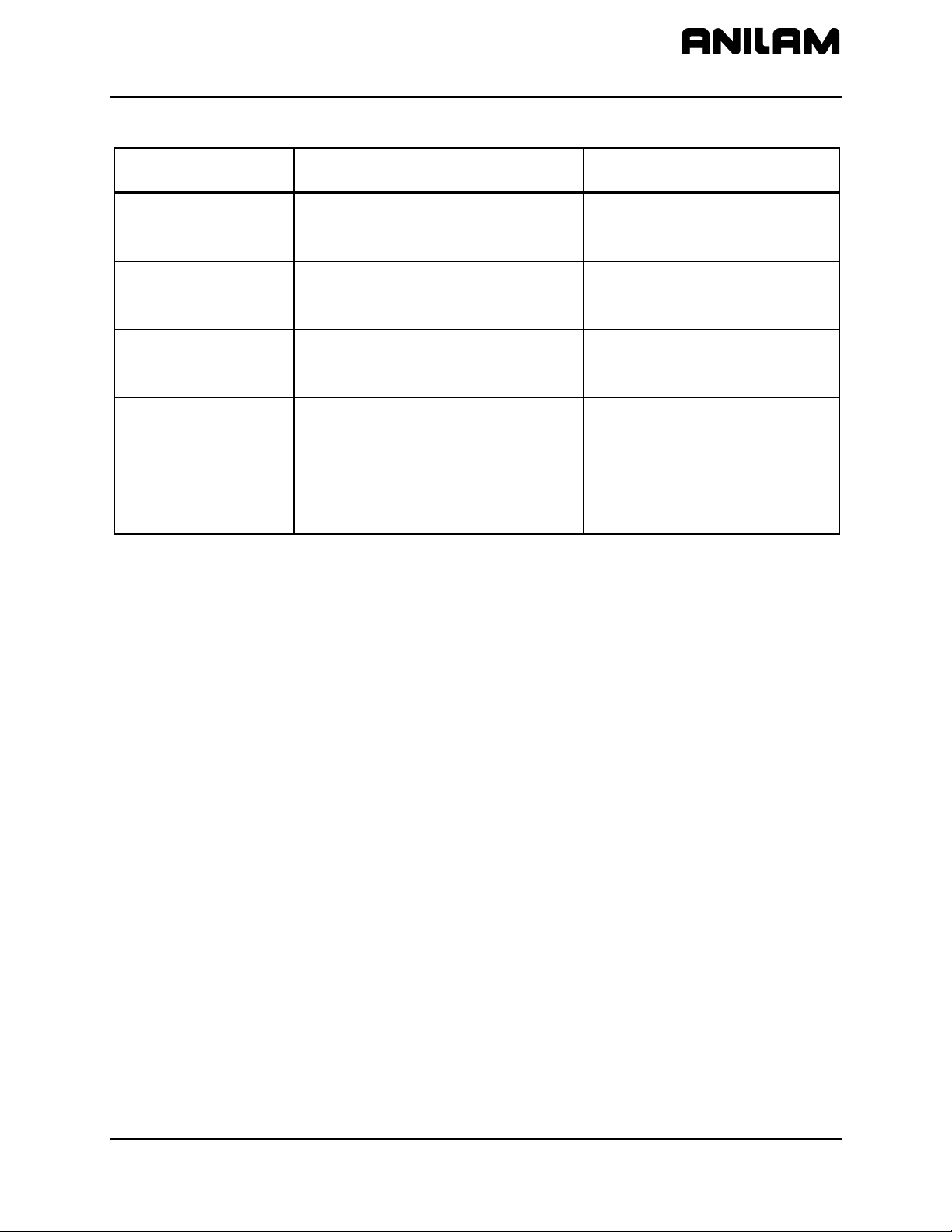
Table 1-2, Keypad Keys
Name Key Face
ARROWS
CLEAR
SHIFT
SPACE

CNC Setup Utility Manual
P/N 70000490C - Setup Utility Concepts
All rights reserved. Subject to change without notice.
10-December-04
1-3
Axis Keys
Some parameters require that you specify an axis. Use the X, Y, Z, or U
key to specify the axis.
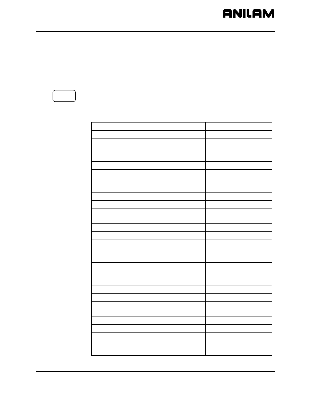
Console Switches/Manual Panel Keys
Console switches and Manual Panel Keys are referred to as shown in
Table 1-3.
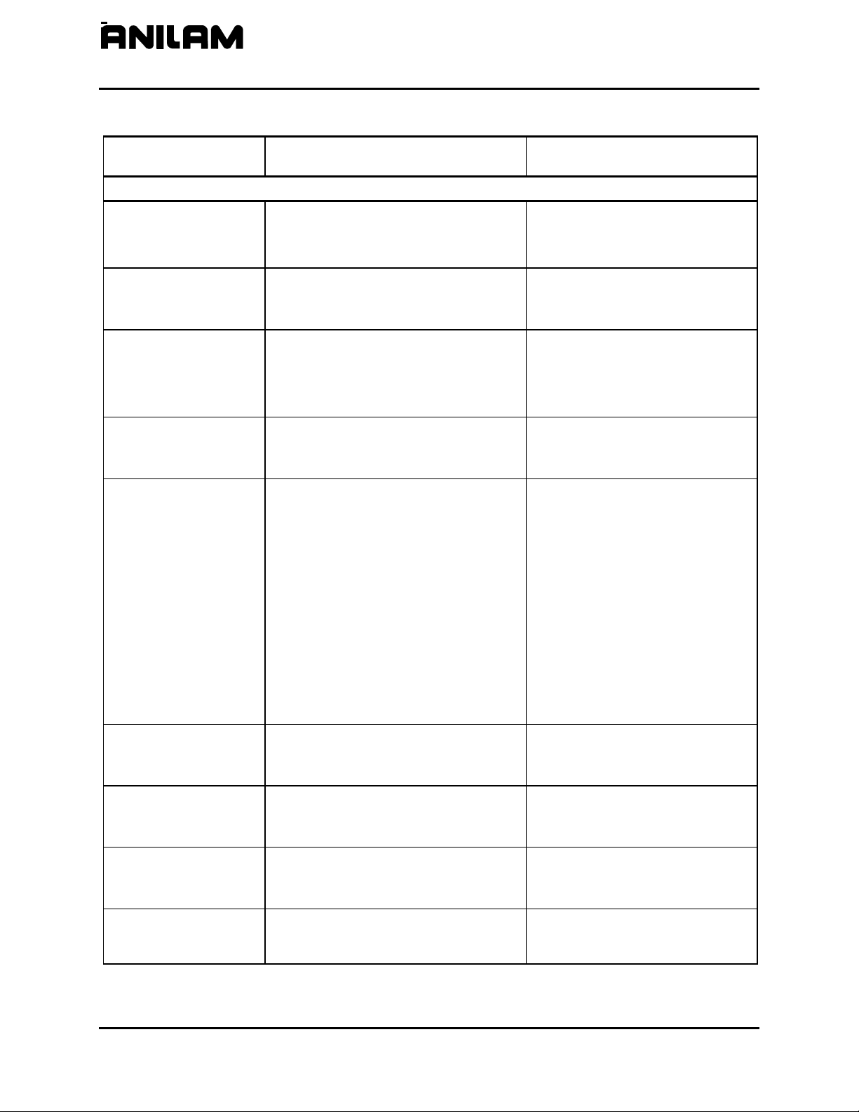
Table 1-3, Console Switches/ Manual Panel Keys
Name Switch/Key
Axis Selector Switch
X
Y
Z
U
AXIS
Jog Selector Switch
FEED
RAPID
Feedrate OVERRIDE Switch
Spindle OVERRIDE Switch
E-Stop Key
Jog Plus Key
Jog Minus Key
Servo Reset Key
Start Key
Hold Key
(Continued…)
SPINDLE
CNC Setup Utility Manual
P/N 70000490C - Setup Utility Concepts
All rights reserved. Subject to change without notice.
10-December-04
1-4
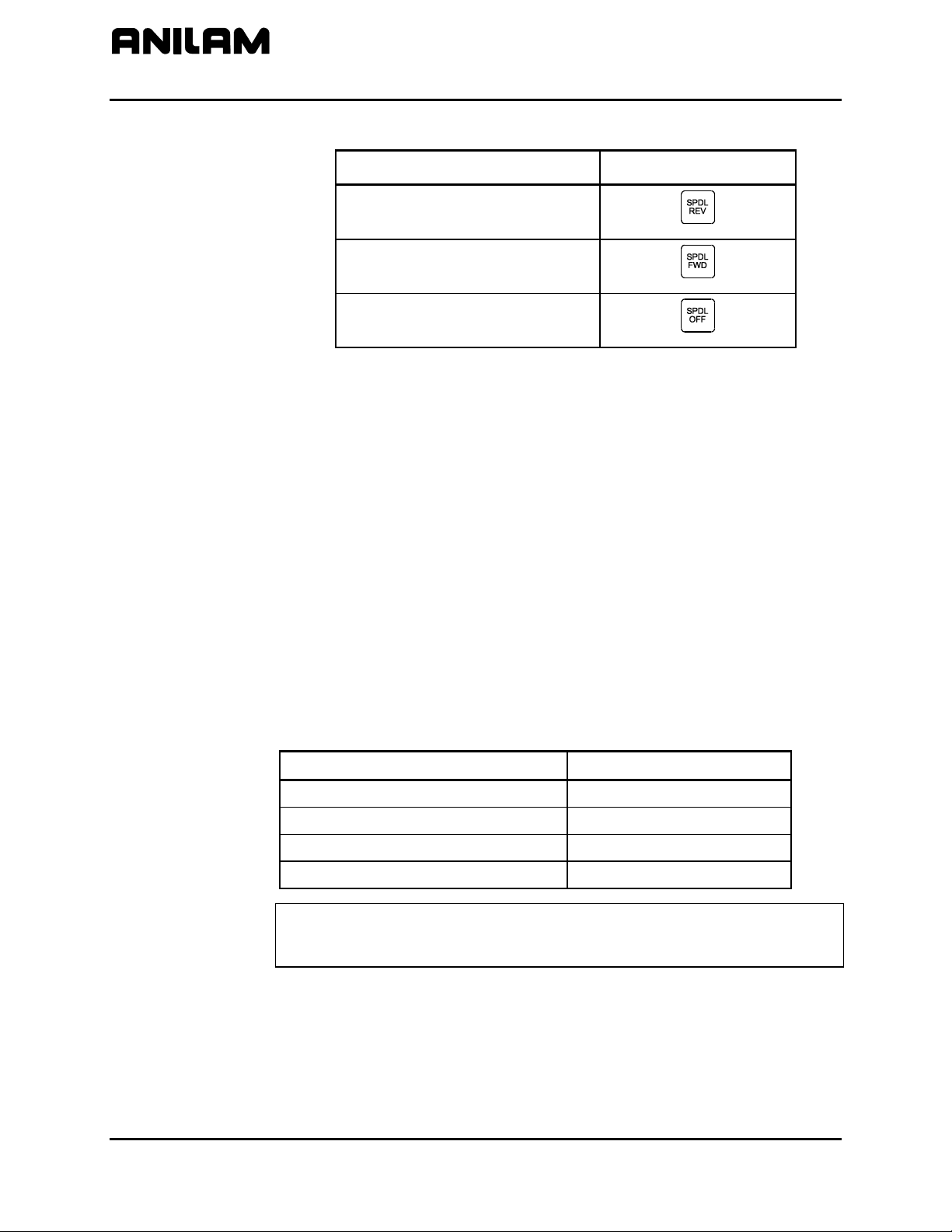
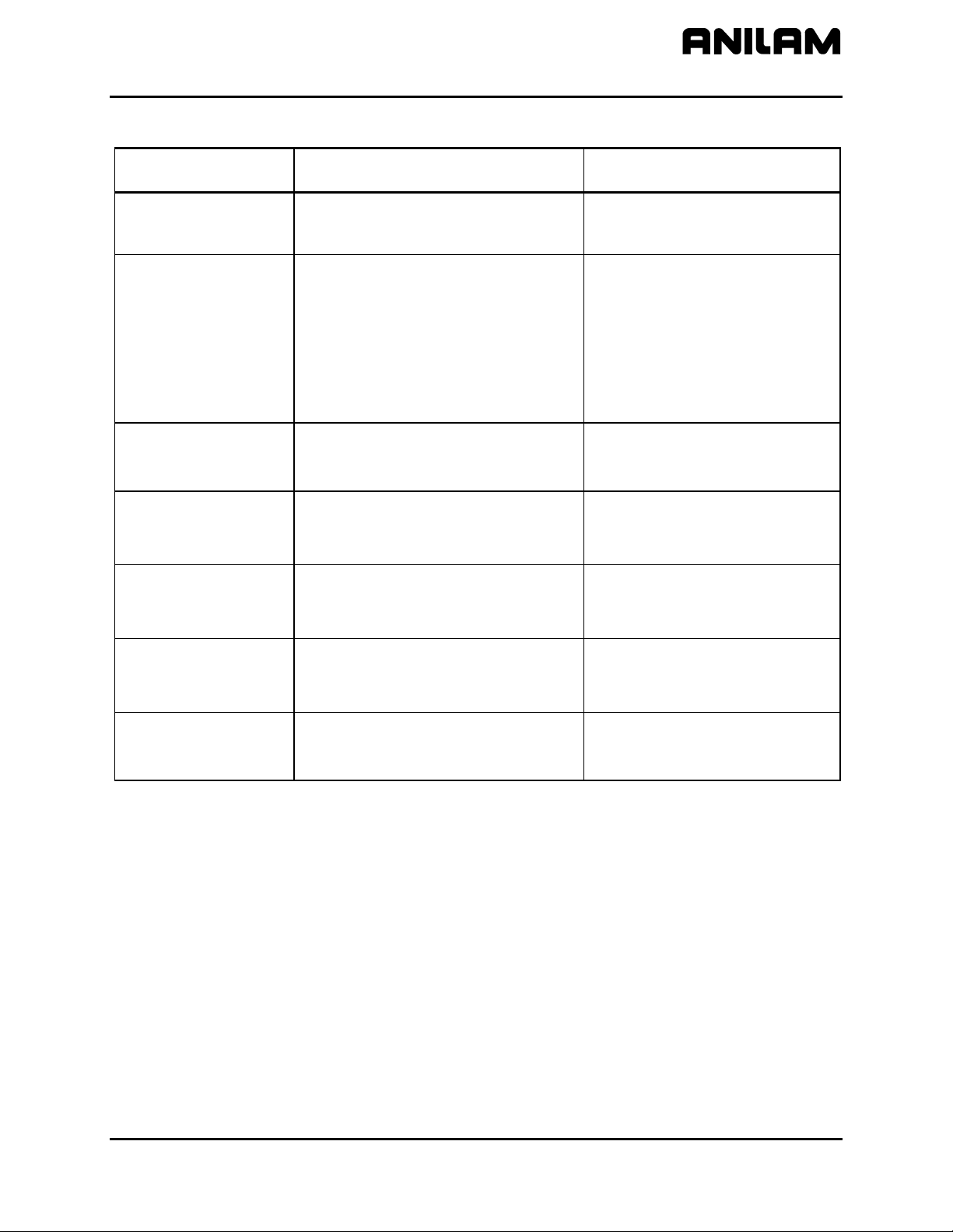
Table 1-3, Console Switches/ Manual Panel Keys (Continued)
Name Switch/Key
Spindle Reverse Key
Spindle Forward Key
Spindle Off Key
ENTER Key
Press
ENTER to enter parameters into the system.
Highlighting Menu Options
Press Up Arrow (F3
) and Down Arrow (F4) to highlight menu selections
in the Setup Utility. The corresponding arrow keys can also be used.
Exiting a Screen
Press Exit (F10) to return to the previous screen.
Password Restricted Parameters
Some machine parameters are protected by passwords. The CNC
provides four access levels of passwords. Operators are assigned limited
access, which allows them to set parameters used in normal machine
operations. Service and factory technicians require a higher level of
access. The Programmable I/O Interface requires a separate password.
See Table 1-4 for default machine passwords.
Table 1-4, Default Machine Passwords
Access Level Password Level
Limited – Operator 159
Service Technician Z48
Factory Technician Reserved for factory use
Programmable Logic Controller IPI
NOTE: Service supersedes Limited. Factory level is the highest and
supersedes all, except IPI, which is independent of the other
passwords.

CNC Setup Utility Manual
P/N 70000490C - Setup Utility Concepts
All rights reserved. Subject to change without notice.
10-December-04
1-5
Changing Protected Parameters
To change protected parameters, enter a password when the CNC
displays the password prompt.
NOTE: You are only required to type a password once during Setup.
However, when you exit the Setup Utility and re-enter, you will
again be prompted for a password.
Saving Changes to Setup Parameters
When you exit the Setup Utility menu after you have changed any
parameters, the CNC displays the prompt “Save Changes?”.
Select one of the following:
Yes (F1) to save the changes.
No (F2) to cancel the changes.
Cancel (F9) to return to the Setup Utility Menu.
NOTE: When No (F2) is pressed, all parameters revert to the settings
prior to changes.
All configuration parameters are saved in a configuration file,
(P6MCFG.CFG). Every time a parameter is changed, the configuration
file is saved; the CNC automatically creates a backup file,
(P6MCFG.BAK). The CNC provides utilities to manage the configuration
file. Refer to “Section 4 - Configuration Utilities
” for detailed information.
Setting Parameters in Setup Utility
To set parameters in the Setup Utility, do the following:
1. Highlight the menu in which the parameter appears and press
ENTER.
Change the parameter by following one of the steps mentioned below:
In some cases a parameter can only have two selections. Pressing
ENTER changes from one value to the other.
In some cases, a parameter may have more than two selections and
pressing
ENTER will display a pop-up menu with the list of selections.
Highlight the desired selection and press
ENTER.
In other cases, the CNC will highlight an entry field and you will be
allowed to type the value for the parameter. Type the desired value,
or setting, and press
ENTER.

CNC Setup Utility Manual
P/N 70000490C - Setup Utility Concepts
All rights reserved. Subject to change without notice.
10-December-04
1-6
Using Valid Parameter Ranges
All parameters entered in an entry field must be within the valid range for
the parameter. If the value entered is not within the valid range, an error
message is displayed. The error message shows the valid range for the
parameter. Pressing F10 or
CLEAR can clear the error message. Once
the error message is cleared, you can enter another value. The previous
value can be restored by pressing
UP ARROW and then ENTER.
Accessing Setup Utility
To access the Setup Utility menus, do the following:
1. Turn on the CNC.
When the CNC is turned on, the CNC software starts automatically.
The CNC displays messages to indicate the status of the startup.
When the CNC software has successfully started, the CNC displays
ANILAM Company information and the software version number.
2. Press (F10) to continue.
The CNC displays the Software Options screen.
3. Use the ARROW keys to highlight Setup
Utility. Press ENTER.
If already in Manual mode, access the Software Options screen by
pressing SHIFT + F10. The servos must be off or the CNC will not allow
you to exit Manual mode.
In either case, the CNC displays the Setup
Options Menu. Refer to
Map 1
, Menu A. This menu allows you to access the setup parameters.
Units of Measurement
The Units of Measurement parameter specifies the units used to enter
dimensional data. If you are using mixed data, input data in one format
(inch or mm) first. Change the format (inch or mm) and enter the rest of
the data. You can change the units as many times as you need to. By
using the proper units you do not need to convert values, but can enter
data precisely (that is, no rounding during conversion). See MC_1002:
Default units. [Default: Inch]
All dimensional data will be displayed according to the units specified in
this parameter.
6400M
The only exception to this rule is the dimensional parameter
corresponding to rotary axes. If the auxiliary axis (that is, U) is configured
as a rotary axis, then the unit is always in degrees or degrees per minute
(that is, deg/min).
6000M-4X
CNC Setup Utility Manual
P/N 70000490C - Machine Constants
All rights reserved. Subject to change without notice.
10-December-04
2-1
Section 2 - Machine Constants
The Machine Constants configures the settings for the CNC.
Machine Constants Group Assignments
Refer to Table 2-1 for range assignments.
6400M
The Setup Utility displays Machine Constants for axes X, Y, Z, and U.
Machine Constants for the U-axis need to be set when the U-axis is
used in a 6000M-4X.
Table 2-1, Machine Constant Group Assignments
Setup Parameter Group MC Range
Control Software MC_1000 – MC_1099
Draw Mode MC_1100 – MC_1199
User Definable Variables MC_1120 – MC_1149
Tool Probe Variables MC_1150 – MC_1199
Editor Mode MC_1200 – MC_1299
Program Directory MC_1300 – MC_1349
RS-232 Communication MC_1350 – MC_1374
Printer MC_1375 – MC_1399
X-axis Setup MC_2000 – MC_2099
Y-axis Setup MC_2100 – MC_2199
Z-axis Setup MC_2200 – MC_2299
U-axis Setup MC_2300 – MC_2399
Spindle axis Setup MC_2900 – MC_2999
Linear Correction Compensation MC_3000 – MC_3014
Skew Error Compensation MC_3015 – MC_3029
Backlash Compensation MC_3030 – MC_3049
Ballscrew Compensation MC_3050 – MC_3099
Software Limits MC_4000 – MC_4019
Continuous Path MC_4020 – MC_4029
Position Error Check (PEC) MC_4030 – MC_4049
Jog Return Position MC_4050 – MC_4059
Direct Numeric Control (DNC) MC_4060 – MC_4065
Handwheel MC_4100 – MC_4149
Home MC_4200 – MC_4249
Miscellaneous MC_4300 – MC_4399
M-Code Macro Call MC_4400 – MC_4419
Tool Management MC_5000 – MC_5099
Interface MC_5100 – MC_5149
More Parameters MC_5200 – MC_5299
6000M-4X

CNC Setup Utility Manual
P/N 70000490C - Machine Constants
2-2 All rights reserved. Subject to change without notice.
10-December-04
Machine Constants Setup
Refer to Table 2-2 for the parameter descriptions and setting information.
The table has subheadings to help you identify the parameters; these
subheadings do not display in the software or the Off-line. The default
value in Table 2-2 is bold where there are multiple selections available.
NOTE: Press
ENTER to toggle the available settings.
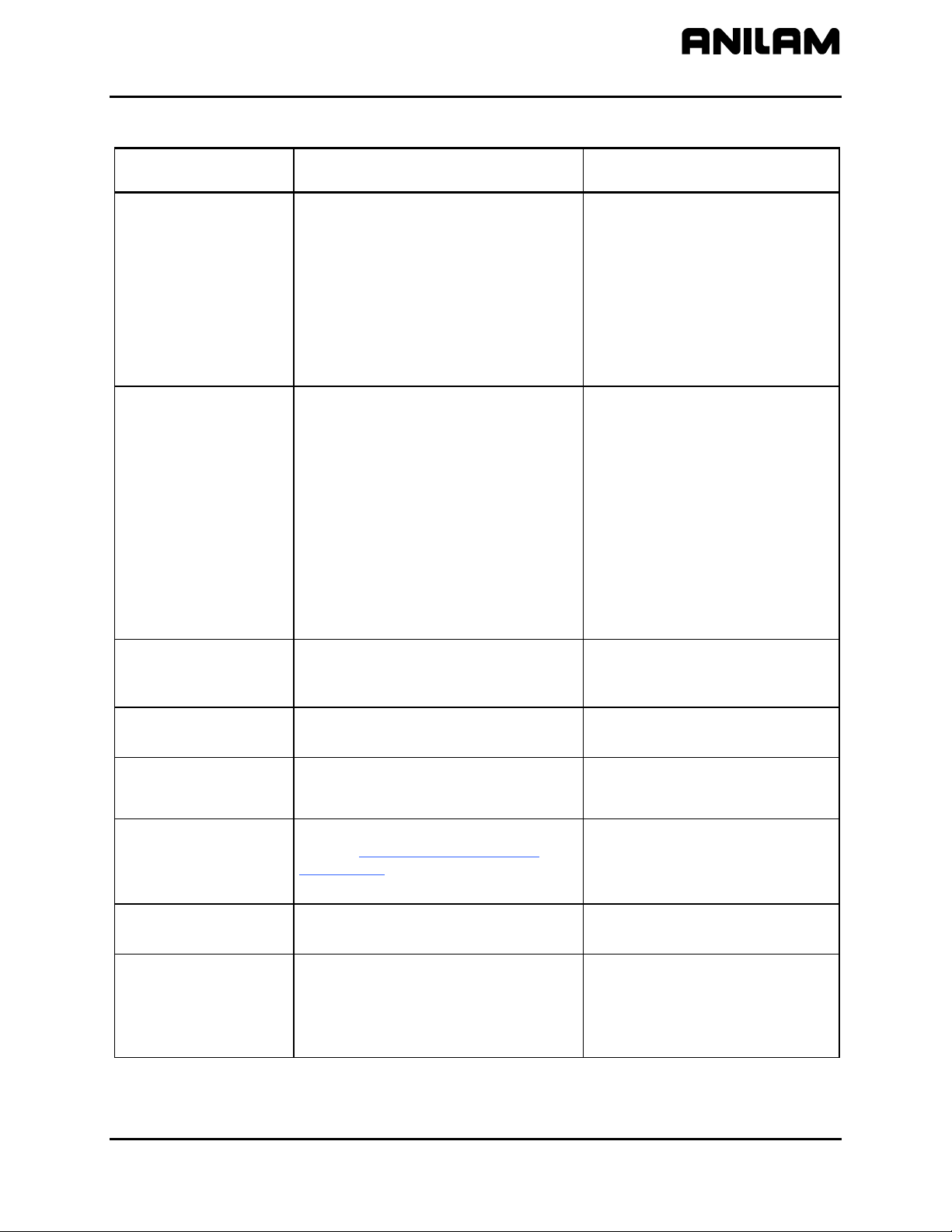
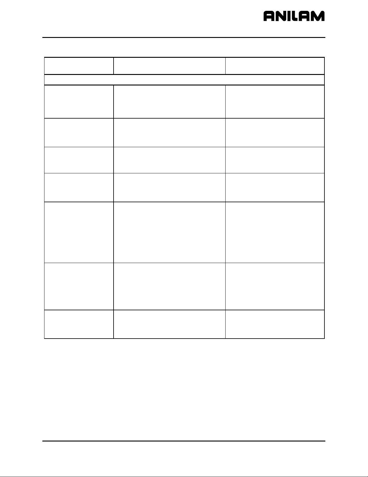
Table 2-2, Machine Constants Setup
Machine Constant
Parameter
Function Settings
Control Software Setup Parameters
MC_1000:
Default axis display
Switches the default axis display
between large and normal.
Large - Configures the axis display
to show enlarged X, Y, Z, and
U Program position display
only.
Normal - Configures the axis
display to show Machine,
Program, Target, and
Distance To Go displays.
[Default]
MC_1001:
Default plane
A plane defines movement along two
axes, excluding a third. Thus, planar
movement is two-dimensional. Circular
moves and tool diameter compensation
are confined to the plane chosen by the
user. (Linear moves can occur in all
three axes simultaneously.).
XY - (top view) displays program in
X and Y. [Default]
XZ - displays program in X and Z.
YZ - displays program in Y and Z.
MC_1002:
Default units
Switches the default measurement units
(Inch/MM Modes).
Inch – Activates Inch Mode as
default. [Default]
MM – Activates MM (millimeter)
Mode as default.
MC_1003:
Default axis values
Switches Absolute/ Incremental default
mode (determines how axis values for
arcs, lines, and other moves are
measured).
Absolute – Makes every move in
reference to an Absolute Zero
position (Program Zero or Part
Zero). [Default]
Incremental – Makes each move in
reference to the last
programmed endpoint.
(Continued…)
CNC Setup Utility Manual
P/N 70000490C - Machine Constants
All rights reserved. Subject to change without notice.
10-December-04
2-3
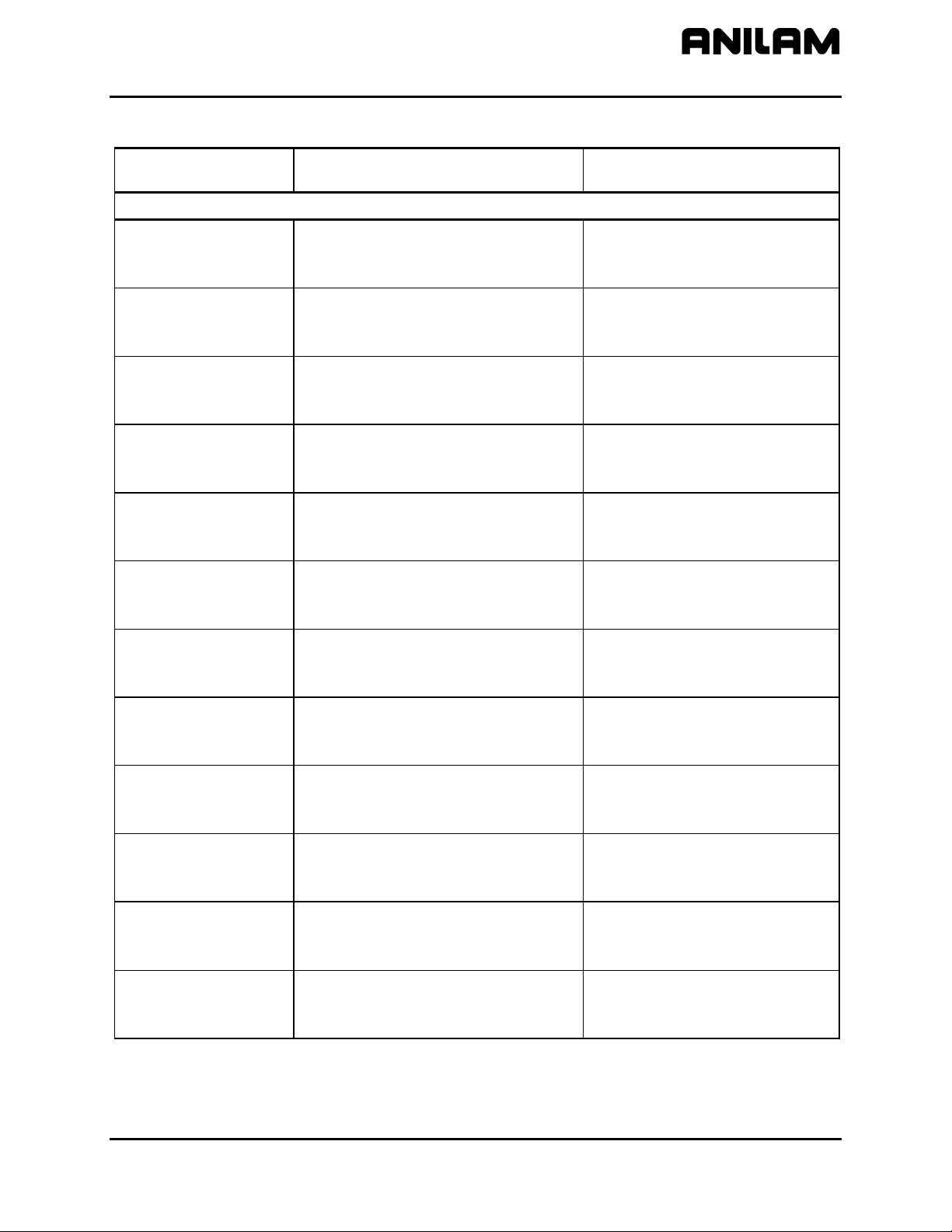
Table 2-2, Machine Constants Setup (Continued)
Machine Constant
Parameter
Function Settings
MC_1004:
Circle adjustments
Specifies whether circle centers or
endpoints will be adjusted. Circle
centers require adjustment when the
CNC encounters incorrect circle center
or end-point coordinates.
Center - Adjusts the position of the
circle center when the CNC
encounters incorrect
coordinates for either a circle
center or endpoint.
End-Point - Adjusts the position of
the circle endpoint when the
CNC encounters incorrect
coordinates for either a circle
center or end-point. [Default]
MC_1005:
Circle centers
Switches the default mode for
programmed circle center coordinates.
Absolute - CNC interprets
programmed circle center
coordinates as Absolute
values.
Incremental - CNC interprets
programmed circle center
coordinates as Incremental
values. [Default]
Modal - CNC interprets
programmed circle center
coordinates based on current
Incremental or Absolute
setting.
MC_1006:
Maximum arc
correction
Specifies the maximum amount of
correction the CNC will apply to an arc
block before declaring an error.
Range (0.000000–1.000000)
0.005000 [Default]
MC_1007:
Internal accuracy
Maximum accuracy available (system
resolution).
Range (0.00000001–0.00100000)
0.00000100 [Default]
MC_1008:
External accuracy
Specifies the maximum system
accuracy obtainable on a given machine
(machine resolution).
Range (0.00000001–0.00100000)
0.00010000 [Default]
MC_1009:
Compensation cutoff
angle
Minimizes wasted travel on acute angle.
Refer to Figure 2-1, Compensation
Cutoff Angle.
Range (1.0–90.0)
15.0 (degrees) [Default]
MC_1011:
User macro file
Specifies macro filename created by
user.
USERCANN.G [Default]
MC_1012:
Load user macro file
Specifies whether to load user macro at
system startup.
No - Does not automatically load
user macro at startup.
[Default]
Yes - Automatically loads user
macro at startup.
(Continued…)
CNC Setup Utility Manual
P/N 70000490C - Machine Constants
2-4 All rights reserved. Subject to change without notice.
10-December-04
Table 2-2, Machine Constants Setup (Continued)
Machine Constant
Parameter
Function Settings
MC_1013:
Disk access marker
Activates/deactivates the Disk access
marker.
On - Activates the Disk access
marker. When the CNC is
reading/writing information
from/to a disk the Disk access
marker is displayed in the
upper-left corner of the
screen. The Disk access
marker looks like a small
arrow. [Default]
Off - Deactivates Disk access
marker.
MC_1014:
Max. memory
allocated
(in MB-bytes)
Used only with off-line software. Limits
the amount of memory available to the
software. This parameter is used to limit
the amount of memory available in
multitasking environments that provide
virtual memory.
Range (2–128)
4 (MB) [Default]
MC_1015:
Force simulation
mode
In Simulation Mode, the CNC does not
generate motor and I/O signals. The
CNC starts in Simulation Mode. Moves
can be commanded and displayed, but
no actual machine movements occur.
Yes - Enable [Default]
No - Disable
MC_1016:
Screen blanking delay
(minutes)
Specifies the screen blanking delay
period, in minutes. The delay will be the
time between a detected screen idle
condition and the activation of the
screen saver. To reactivate, press any
key.
Range (0–20160)
5 (minutes) [Default]
MC_1032:
Enable radius
compensation error
checking
Activates the tool radius compensation
error checking. The error checking is
designed to eliminate simple gouges
caused by overcompensation.
Yes - Enable
No – Disable [Default]
(Continued…)
CNC Setup Utility Manual
P/N 70000490C - Machine Constants
All rights reserved. Subject to change without notice.
10-December-04
2-5
Table 2-2, Machine Constants Setup (Continued)
Machine Constant
Parameter
Function Settings
Draw Mode Setup Parameters
MC_1100:
Restore Draw to
previous session
Sets the CNC to re-activate the last
active session when you re-enter Draw.
Yes - CNC re-activates last
session when Draw activated.
[Default]
No - CNC ignores parameter.
MC_1101:
Default program block
mode
Sets default mode in Draw.
Auto [Default]
S.Step
Motion
MC_1102:
Display program text
Determines whether program text is
displayed in Draw Mode.
Yes - Shows program text.
[Default]
No - Does not show program text.
MC_1103:
Grid
Activates/deactivates grid as a dotted or
solid line.
None - Deactivates grid. [Default]
Solid - Activates solid line grid.
Dotted - Activates dotted line grid.
MC_1104:
Grid size
Determines the size of the grid (in the
active Inch or MM Mode).
NOTE: The CNC converts the set grid
value if the measurement unit is
changed. For example: if the Grid Size
is set for 1 in Inch Mode and you switch
to MM Mode, the CNC changes the Grid
Size to 25.4 mm (equal to 1 inch).
Range (0.0–25,400.0)
1.0 [Default]
(If the CNC is in Inch Mode, each
square in the grid will be one
square inch in size for this setting.)
MC_1105:
Tool display
Turns the tool display On and Off.
On - The tool (as defined by the
Tool Location Code and
Radius in the Tool Page) will
be displayed as it cuts the
workpiece. [Default]
Off - No tool is displayed.
MC_1106:
Default tool type
Determines shape of displayed tool. None - No tool shown
Flat - Flat-end tool shown [Default]
Ball - Ball-end tool shown
(Continued…)
CNC Setup Utility Manual
P/N 70000490C - Machine Constants
2-6 All rights reserved. Subject to change without notice.
10-December-04
Table 2-2, Machine Constants Setup (Continued)
Machine Constant
Parameter
Function Settings
MC_1107:
Cutter compensation
in Draw
Activates/deactivates cutter
compensation in Draw Modes.
Ignore - CNC will not show
compensated moves (if any)
used in the program.
Use - CNC shows compensated
and non-compensated
programmed moves.
Both - CNC runs the program
twice. First, the program is
run without compensated
moves. Second, the program
is run showing compensated
moves. This provides a
comparison of the two paths
to determine programming
errors related to
compensation. [Default]
MC_1108:
Draw view
Determines perspective of Draw view.
XY - (top view) displays program in
X and Y. [Default]
XZ - displays program in X and Z.
YZ - displays program in Y and Z.
ISO - displays program in X, Y,
and Z.
MC_1109:
Aspect ratio
correction factor
Corrects circularity problems with
display of circles and drawings in
general. In cases where a circle may
look distorted (that is, like an egg), this
parameter can be used to make the
circle look like a TRUE circle.
Increasing the number will make the
circle taller and skinnier; decreasing the
number will make the circle shorter and
fatter.
Range (0.01–10.00)
1.47 [Default]
MC_1110:
Save/Restore Draw
image when using
Edit
Saves draw image when user switches
to Edit Mode. In Draw Mode, when the
Edit (F2) soft key is pressed, the CNC
switches to Edit Mode. The user later
re-enters the Draw Mode when you exit
Edit Mode. If this option is enabled
(Yes), the CNC restores the image on
the screen prior to entering Edit. This
image will correspond to the part
program drawing.
Yes - Saves draw image. [Default]
No - Does not save draw image.
(Continued…)
CNC Setup Utility Manual
P/N 70000490C - Machine Constants
All rights reserved. Subject to change without notice.
10-December-04
2-7
Table 2-2, Machine Constants Setup (Continued)
Machine Constant
Parameter
Function Settings
User Definable Variables Setup Parameters
MC_1120:
User definable
variable #1120
Variable defined by user to be used in
general CNC programming.
Integer value: 0 to 99999
Range (-99999–99999)
0 [Default]
MC_1121:
User definable
variable #1121
Variable defined by user to be used in
general CNC programming.
Integer value: 0 to 99999
Range (-99999–99999)
0 [Default]
MC_1122:
User definable
variable #1122
Variable defined by user to be used in
general CNC programming.
Integer value: 0 to 99999
Range (-99999–99999)
0 [Default]
MC_1123:
User definable
variable #1123
Variable defined by user to be used in
general CNC programming.
Integer value: 0 to 99999
Range (-99999–99999)
0 [Default]
MC_1124:
User definable
variable #1124
Variable defined by user to be used in
general CNC programming.
Integer value: 0 to 99999
Range (-99999–99999)
0 [Default]
MC_1125:
User definable
variable #1125
Variable defined by user to be used in
general CNC programming.
Integer value: 0 to 99999
Range (-99999–99999)
0 [Default]
MC_1126:
User definable
variable #1126
Variable defined by user to be used in
general CNC programming.
Integer value: 0 to 99999
Range (-99999–99999)
0 [Default]
MC_1127:
User definable
variable #1127
Variable defined by user to be used in
general CNC programming.
Integer value: 0 to 99999
Range (-99999–99999)
0 [Default]
MC_1128:
User definable
variable #1128
Variable defined by user to be used in
general CNC programming.
Integer value: 0 to 99999
Range (-99999–99999)
0 [Default]
MC_1129:
User definable
variable #1129
Variable defined by user to be used in
general CNC programming.
Integer value: 0 to 99999
Range (-99999–99999)
0 [Default]
MC_1130:
User definable
variable #1130
Variable defined by user to be used in
general CNC programming.
Unit based (Inch or MM).
Range (-25000.0000–25000.0000)
0.0000 [Default]
MC_1131:
User definable
variable #1131
Variable defined by user to be used in
general CNC programming.
Unit based (Inch or MM).
Range (-25000.0000–25000.0000)
0.0000 [Default]
(Continued…)
CNC Setup Utility Manual
P/N 70000490C - Machine Constants
2-8 All rights reserved. Subject to change without notice.
10-December-04
Table 2-2, Machine Constants Setup (Continued)
Machine Constant
Parameter
Function Settings
MC_1132:
User definable
variable #1132
Variable defined by user to be used in
general CNC programming.
Unit based (Inch or MM).
Range (-25000.0000–25000.0000)
0.0000 [Default]
MC_1133:
User definable
variable #1133
Variable defined by user to be used in
general CNC programming.
Unit based (Inch or MM).
Range (-25000.0000–25000.0000)
0.0000 [Default]
MC_1134:
User definable
variable #1134
Variable defined by user to be used in
general CNC programming.
Unit based (Inch or MM).
Range (-25000.0000–25000.0000)
0.0000 [Default]
MC_1135:
User definable
variable #1135
Variable defined by user to be used in
general CNC programming.
Unit based (Inch or MM).
Range (-25000.0000–25000.0000)
0.0000 [Default]
MC_1136:
User definable
variable #1136
Variable defined by user to be used in
general CNC programming.
No units assigned.
Range (-99999.0000–99999.0000)
0.0000 [Default]
MC_1137:
User definable
variable #1137
Variable defined by user to be used in
general CNC programming.
No units assigned.
Range (-99999.0000–99999.0000)
0.0000 [Default]
MC_1138:
User definable
variable #1138
Variable defined by user to be used in
general CNC programming.
No units assigned.
Range (-99999.0000–99999.0000)
0.0000 [Default]
MC_1139:
User definable
variable #1139
Variable defined by user to be used in
general CNC programming.
No units assigned.
Range (-99999.0000–99999.0000)
0.0000 [Default]
MC_1140:
User definable
variable #1140
Variable defined by user to be used in
general CNC programming.
Unit based (Inch or MM).
Range (-25000.0000–25000.0000)
0.0000 [Default]
MC_1141:
User definable
variable #1141
Variable defined by user to be used in
general CNC programming.
Unit based (Inch or MM).
Range (-25000.0000–25000.0000)
0.0000 [Default]
MC_1142:
User definable
variable #1142
Variable defined by user to be used in
general CNC programming.
Unit based (Inch or MM).
Range (-25000.0000–25000.0000)
0.0000 [Default]
MC_1143:
User definable
variable #1143
Variable defined by user to be used in
general CNC programming.
Unit based (Inch or MM).
Range (-25000.0000–25000.0000)
0.0000 [Default]
MC_1144:
User definable
variable #1144
Variable defined by user to be used in
general CNC programming.
Unit based (Inch or MM).
Range (-25000.0000–25000.0000)
0.0000 [Default]
CNC Setup Utility Manual
P/N 70000490C - Machine Constants
All rights reserved. Subject to change without notice.
10-December-04
2-9
Table 2-2, Machine Constants Setup (Continued)
Machine Constant
Parameter
Function Settings
MC_1145:
User definable
variable #1145
Variable defined by user to be used in
general CNC programming.
Unit based (Inch or MM).
Range (-25000.0000–25000.0000)
0.0000 [Default]
MC_1146:
User definable
variable #1146
Variable defined by user to be used in
general CNC programming.
Unit based (Inch or MM).
Range (-25000.0000–25000.0000)
0.0000 [Default]
MC_1147:
User definable
variable #1147
Variable defined by user to be used in
general CNC programming.
Unit based (Inch or MM).
Range (-25000.0000–25000.0000)
0.0000 [Default]
MC_1148:
User definable
variable #1148
Variable defined by user to be used in
general CNC programming.
Unit based (Inch or MM).
Range (-25000.0000–25000.0000)
0.0000 [Default]
MC_1149:
User definable
variable #1149
Variable defined by user to be used in
general CNC programming.
Unit based (Inch or MM).
Range (-25000.0000–25000.0000)
0.0000 [Default]
(Continued…)
CNC Setup Utility Manual
P/N 70000490C - Machine Constants
2-10 All rights reserved. Subject to change without notice.
10-December-04
Table 2-2, Machine Constants Setup (Continued)
Machine Constant
Parameter
Function Settings
Tool Probe Variables Setup Parameters
MC_1150:
3-D probe type
Transmission type used for the installed
3-D touch probe.
Corded [Default]
Cordless
MC_1151:
Nominal probe stylus
diameter
The overall nominal probe stylus
diameter.
Range (0.0000–51.0000)
0.0000 [Default]
MC_1152:
Maximum stroke from
home for first pick
The distance from machine Z home with
the shortest tool or the spindle face to
just below the probe stylus top as the
maximum stroke for the initial probe
pick.
Range (0.0000–999.0000)
0.0000 [Default]
MC_1153:
RPM for calibration
and tool measurement
The spindle spin RPM for tool touch. Range (100–1000)
0 (rev/min) [Default]
MC_1154:
Probe orientation
Sets the probe orientation. Range (-2–2)
1 Probe is pointing to the right as
you are facing the machine in
the +X direction.
-1 Probe is pointing to the left of
the machine in the -X direction.
0 [Default]
2 Probe is pointing away from
you, toward the back of the
machine in the +Y direction.
-2 Probe is pointing toward you,
toward the front of the machine
in the –Y direction.
MC_1155:
Z first pick, FAST
feed-rate
Sets user definable FAST feed-rate. Range (2.5–2540.0)
0.0 [Default]
MC_1156:
Z first pick, MEDIUM
feed-rate
Sets user definable MEDIUM feed-rate. Range (2.5–508.0)
0.0 [Default]
MC_1157:
Z first pick, SLOW
feed-rate
Sets user definable SLOW feed-rate. Range (0.1–254.0)
0.0 [Default]
MC_1158:
Z retract amount
Sets user definable distance the tool will
back away on the Z-axis after it touches
the probe.
Range (0.0100–25.400)
0.0000 [Default]
(Continued…)
CNC Setup Utility Manual
P/N 70000490C - Machine Constants
All rights reserved. Subject to change without notice.
10-December-04
2-11
Table 2-2, Machine Constants Setup (Continued)
Machine Constant
Parameter
Function Settings
MC_1159:
XY retract amount
Sets user definable distance the tool will
back away on the X-axis or Y-axis after
it touches the probe.
Range (0.0100–25.400)
0.0000 [Default]
MC_1160:
Z rapid to start
position from home
Set the longest tool in the spindle and
bring the Z-axis to machine home. With
a tape measure, measure the distance
from the tool tip to within 0.5” (12.7 mm)
above the top of the probe stylus and
enter that number. When using G151,
this will cause the tool to rapid to this
position in the Z-axis before starting the
initial probe touch in the Z-axis.
Range (0.0000–999.0000)
0.0000 [Default]
MC_1161:
Diameter of tool probe
gauge
Sets the probe calibration standard
diameter.
Range (0.1000–508.0000)
0.0000 [Default]
MC_1162:
Positioning feedrate
normally
Feedrate used for positioning the probe
in protected mode.
Typical value: 200 inches/minute (IPM).
Range (0.1–25400.0)
0.0 [Default]
MC_1163:
First touch feedrate
Feedrate used for positioning for the
initial pick.
Typical value: 50 inches/minute (IPM).
Range (0.1–2540.0)
0.0 [Default]
MC_1164:
Nominal probe stylus
ball radius
Diameter of the probe stylus divided by
2.
Range (0.0100–25.4000)
0.0000 [Default]
MC_1165:
Diameter of spindle
probe gauge
The exact diameter of the ring gauge
used for probe calibration.
Range (0.1000–508.0000)
0.0000 [Default]
(Continued…)
CNC Setup Utility Manual
P/N 70000490C - Machine Constants
2-12 All rights reserved. Subject to change without notice.
10-December-04
Table 2-2, Machine Constants Setup (Continued)
Machine Constant
Parameter
Function Settings
Editor Mode Setup Parameters
MC_1200:
Restore Editor to
previous session
If Yes (enabled), when user exits a
program in Edit Mode, the CNC marks
the position where the last edit was
made. The next time the program is
opened, the cursor will be located at
that spot.
Yes - restores to previous session.
[Default]
No - does not restore to previous
session.
MC_1201:
Show top line
Determines whether an optional “top
line” will be displayed in the Edit Mode.
The top line contains the active mode
information and first block of the open
program.
Yes - Displays top line. [Default]
No - Does not display top line.
MC_1202:
Default insert mode
Switches On/Off Default Insert Mode.
Insert Mode inserts new text without
overwriting existing text.
On - Automatically sets Insert
Mode as default. [Default]
Off - Does not automatically set
Insert Mode as default.
MC_1203:
Auto tab to previous
line’s position
This option is available only with off-line
systems or systems with attached
keyboards. When a line is indented, the
CNC uses the indented position as the
first tab position of the following line.
For example, the user indents one line
by four spaces and then moves to the
beginning of the next line by pressing
ENTER. When you press TAB, the cursor
now advances four spaces.
Yes - Enables auto tab to previous
line’s position. [Default]
No - Disables auto tab to previous
line’s position.
MC_1205:
Default tab width
This option is available only with offline
systems or systems with keyboards
attached.
Sets default tab width. Range is 2 to 16
spaces. When you press
TAB, the
cursor advances by the specified
number of spaces.
Range (2–16)
4 (spaces) [Default]
MC_1206:
Create backup
program
A backup program is created when an
edit is made. Each time the program is
edited, the CNC updates the backup
file. The backup program will not
contain an edit until a new edit is made.
Yes - Backup program is created
and maintained.
No - No backup programs are
created. [Default]
(Continued…)
CNC Setup Utility Manual
P/N 70000490C - Machine Constants
All rights reserved. Subject to change without notice.
10-December-04
2-13
Table 2-2, Machine Constants Setup (Continued)
Machine Constant
Parameter
Function Settings
MC_1208:
Case sensitive Find
Determines whether the Find feature
will search for uppercase and lowercase
letters to determine a match.
Yes - Find search parameter looks
for words that exactly match
the entered word specific to
capitalization and style.
No - Find search parameter looks
for the entered word,
regardless of capitalization
and style. [Default]
MC_1209:
Memory reserved from
editor (in K-bytes)
Specifies the amount of memory that
the editor will not allocate (that is,
leaving free).
Range (16–32000)
300 (KB) [Default]
Program Directory Setup Parameters
MC_1300:
Program directory
pattern
Type of programs displayed.
Plus sign ‘+’ can be used to specify
multiple types.
*.G+*.M [Default]
MC_1301:
Program directory
display mode
Specifies what program information will
be displayed in the Program Directory.
Short - Filename and extension
only [Default]
Long - Detailed program
information, including file size,
etc.
MC_1302:
Program directory
sort order
Specifies the order in which programs
are listed in the Program Directory.
Ignore - CNC ignores parameter.
Name - Alphanumeric order by
filename [Default]
Extension - Alphanumeric order by
file extension
Size - By file size
Date - By date program was
created
MC_1303:
Automatically check
disk at startup
For machines equipped with hard
drives, specifies whether and how often
CNC will check the hard drive.
Always
Daily
Weekly
Monthly [Default]
Never
MC_1304:
Delete backup files
during optimize
For machines equipped with hard
drives, specifies whether backup files
will be deleted during hard drive
optimization.
Yes - Backup files deleted during
optimization process [Default]
No - Backup files maintained
during optimization process
MC_1305:
Directory for user
program
CNC will store user programs in
specified directory.
C:\USER [Default]
Enter user directory location
(Continued…)
CNC Setup Utility Manual
P/N 70000490C - Machine Constants
2-14 All rights reserved. Subject to change without notice.
10-December-04
Table 2-2, Machine Constants Setup (Continued)
Machine Constant
Parameter
Function Settings
RS-232 Communication Setup Parameters
MC_1350: Port
Selects a communications port or
disables. Must enable for remote
communications.
COM1, COM2, Disabled
[Default: Disabled]
MC_1351: Baud
Selects a baud. 110, 150, 300, 600, 1200, 2400,
4800, 9600 [Default], or 19200
MC_1352: Parity
Selects parity.
NONE, ODD, or EVEN [Default]
MC_1353:
Data bits
Enters number of data bits.
7 [Default]
8
MC_1354:
Stop bits
Enters number of stop bits. 0
1 [Default]
MC_1355:
Software
Refers to Xon or Xoff or “handshaking”
(transmission/ receipt of data via
RS-232) in communications packages.
On - Enables handshaking
[Default]
Off - Disables handshaking
Printer Setup Parameters
MC_1375:
Default output device
Specifies where file will be printed. PRN [Default]
To print to another file, enter drive,
path, and filename with extension.
If the filename entered is not an
existing file, the CNC creates the
file and transfers the data to the
file. If the filename entered is an
existing file, the CNC overwrites
the data in the file with the print file
data.
MC_1376:
Lines per page
Number of lines to be printed per page
(8.5 X 11”).
Range (1–66)
55 [Default]
Enter desired value
MC_1377:
Page heading
Prints a page heading including
filename, date and time, and page
number.
Yes - Prints heading. [Default]
No - Does not print heading
MC_1378:
Line numbers
Prints line numbers on hard copy of file. Yes - Prints line numbers
No - Select No if no line numbers
are desired [Default]
MC_1381:
Wrap text
Wraps text to the next line if program is
greater than 80 characters.
Yes - Wraps text [Default]
No - Truncates text
(Continued…)

CNC Setup Utility Manual
P/N 70000490C - Machine Constants
All rights reserved. Subject to change without notice.
10-December-04
2-15
Table 2-2, Machine Constants Setup (Continued)
Machine Constant
Parameter
Function Settings
X-axis Setup Parameters
MC_2000:
X Motor Encoder
Connector
The connection to which the motor
encoder for the X-axis is connected.
X15 [Default]
X16
X17
X18
X19
MC_2001:
X PWM Output
Connector
Defines the X-axis Pulse with
Modulation (PWM) output connector.
X55
X51 [Default]
X52
X53
X54
MC_2002:
X Inverter Type
The inverter type identifies the X-axis
inverter being used. Inputting the wrong
inverter type can result in undesired
axis behavior or inverter damage.
SA 411A
SA 201A
SA 301C
SA 411C [Default]
PM 107
PM 115A
PM 123A
PM 132A
PM 148A
PM 207
PM 215A
PM 223A
MC_2003:
X Motor Type
The X-axis motor type is identified by
the motor name. Inputting the wrong
motor number can result in undesired
axis behavior or motor damage.
NONE
AM 820A
AM 820AB
AM 1150A
AM 1150AB
AM 1400C
AM 1400CB
AM 1400A [Default]
AM 1400AB
AM 960A
AM 960AB
AM 1160A
AM 1160AB
AM 1160C
AM 1160CB
AM 1160E
AM 1160EB
AM 1550C
AM 1550CB
AM 1550E
AM 1550EB
AM 1550G
AM 1550GB
AM 1150C
AM 1420C
CNC Setup Utility Manual
P/N 70000490C - Machine Constants
2-16 All rights reserved. Subject to change without notice.
10-December-04
Table 2-2, Machine Constants Setup (Continued)
Machine Constant
Parameter
Function Settings
MC_2004:
X Linear Encoder
Connector
Selects the measuring system input for
the X-axis linear encoder.
NONE [Default]
X1
X2
X3
X4
X6
MC_2005:
X Linear Encoder
Sinewave Period
Provides the number of encoder periods
corresponding to the X-axis
displacement as entered in MC_2006.
The sine signal of the encoder is
interpolated to obtain 1024* the nominal
resolution.
The input frequency of the encoder to
the CNC may not exceed:
350 kHz for an encoder with 1Vpp
signal
NOTE: Both MC_2005 and MC_2006
may be multiplied by the same factor to
obtain integer values. Also, division by
the same factor is possible as long as
the result is an integer.
See “Encoder Resolution Examples
” for
sample calculations.
Range (0–20160)
1 [Default]
MC_2006:
X Linear Encoder µm
per Sinewave
X-axis grating pitch. Range (1–100)
20 [Default]
MC_2007:
X Linear Encoder
Type
Defines the X-axis encoder type.
Lin Enc [Default]
EverTrack
MC_2008:
X Linear Encoder
Signal Type
Defines the signal type for the X-axis
encoder.
1Vpp [Default]
MC_2009:
X Linear Encoder
Phase
Moving the X-axis in a positive direction
should result in a positive count on the
axis display. Likewise, moving an axis
in a negative direction should result in a
negative count on the axis display. If an
axis display does not count in the
appropriate direction, adjust the
Encoder Phase settings to correct the
problem.
NOTE: This is the only way to change
the direction of the count without
making hardware changes.
Not invert [Default]
Invert
CNC Setup Utility Manual
P/N 70000490C - Machine Constants
All rights reserved. Subject to change without notice.
10-December-04
2-17
Table 2-2, Machine Constants Setup (Continued)
Machine Constant
Parameter
Function Settings
MC_2010:
X Ballscrew Pitch
Pitch is the linear distance traveled per
revolution of the X-axis ballscrew.
NOTE: This parameter applies only to
rotary encoders. Do not use if the axis
is using a linear encoder for feedback.
Range (0.00000–30.00000)
0.47244 (inch) [Default]
MC_2011:
X Number of Teeth
Motor
Gearing on the X-axis motor side. Set
at 1 if there is no gear train.
Range (1–200000)
1 [Default]
MC_2012:
X Number of Teeth
Ballscrew
Gearing on the X-axis spindle side. Set
at 1 if there is no gear train.
Range (1–200000)
1 (no gear train) [Default]
MC_2013:
X Motor Encoder
Phase
Invert X-axis motor and encoder count
direction.
Invert [Default]
Not invert
MC_2014:
X DC Bus Voltage
Standard X-axis value 560 (VDC). This
value can be changed is the supply
voltage deviates from the standard
voltage 3*400 (VAC).
Range (100–800)
560 (VDC) [Default]
MC_2015:
X I2t Guarding
The square of the actual current is
integrated to monitor the actual power.
The integration lasts for 10 seconds
with feed motors and 150 seconds for
main spindle motors.
For the limit value, the nominal motor
current is used, multiplied by the factor
from MC_2015. Standard value is
100%.
Range (0–800)
0 Off [Default]
MC_2016:
X Commutation Offset
Speed (rpm)
The X-axis field angle offset (MC_2017)
operates from this speed.
Range (0–40000)
0 (rev/min) [Default]
MC_2017:
X Commutation Offset
Angle (deg)
The X-axis field angle offset is
interpolated between the value zero at
MC_2016 speed and the MC_2017
value at Nmax (maximum) speed
(velocity).
Range (0–360)
0 (degrees) [Default]
MC_2018:
X Velocity Filter
The X-axis velocity filter is suitable for
damping high-frequency spurious
oscillations (>600 Hz).
0 No filter [Default]
1 1
st
order filter (spurious
oscillations less than (<)
approximately 700 Hz)
2 2
nd
order filter (spurious
oscillations greater than (>)
approximately 700 Hz)
(Continued…)
CNC Setup Utility Manual
P/N 70000490C - Machine Constants
2-18 All rights reserved. Subject to change without notice.
10-December-04
Table 2-2, Machine Constants Setup (Continued)
Machine Constant
Parameter
Function Settings
MC_2020:
X Current Control
Gain N<Nom (mV/A)
The X-axis current control (PI) gain is
determined with MC_2020. Both P
(Proportional) and I (Integral)
components can be determined with
just one machine constant.
Range (16–999999)
60000 (mV/A) [Default]
MC_2021:
X Current Control
Gain N>Nom (mV/A)
The X-axis current gain control usually
has to be increased for revolutions
above Nnom. The gain of MC_2021 is
defined at Nmax. When MC_2021 is
set at zero, the gain of MC_2020 is
applied for the whole speed range. The
gain between Nnom and Nmax is
increased linearly.
Range (0–999999)
0 (mV/A) [Default]
MC_2022:
X Vel. Control Prop.
Gain (mAs/rev)
The X-axis proportional gain of the
velocity control loop is set using the
velocity loop gain Kvel. The overall loop
gain depends on the machine constant
value, the motor torque constant, and
the equivalent mass moment of inertia
(related to the motor).
Range (0.1–10000.0)
2.0 (mAs/rev) [Default]
MC_2023:
X Vel. Control Integral
Timecons (.1ms)
X-axis velocity control integral time
constant in tenths of milliseconds.
Range (0.000–100.000)
0.100 (0.1ms) [Default]
MC_2024:
X Vel. Control Integral
Limit (ms)
If the X-axis “limit cycling” effect occurs
during rest, limiting the integral buffer
can compensate it. This compensation
is switched off when MC_2024 = 0.
Realistic input values are between
100–200 milliseconds.
Range (0.00–1000.00)
0.00 (ms) [Default]
MC_2025:
X Vel. Control Diff.
Gain (.1mAs2/rev)
Normally the X-axis differential gain is
not used in the speed controller. The
differential gain reduces oscillations in
the low frequency range (<200 Hz), but
it destabilizes the controller in the higher
frequency range.
Do not use this constant for machine
axis if the motor is coupled to the
spindle via a timing belt.
Range (0.00–1000.00)
0.00 (0.1mAs
2
/rev) [Default]
MC_2026:
X Pos. Control Prop.
Gain (1/min)
Sets the X-axis positional control
proportional gain. The positional control
gain determines the dynamic servo
error for an axis without fast feed.
MC_2026 = 2000 [1/min],
feed = 2000 [mm/min], the dynamic
servo error is feed/MC_2024 = 1 [min].
Range (0.10–100.00)
40.00 (1/min) [Default]
(Continued…)
CNC Setup Utility Manual
P/N 70000490C - Machine Constants
All rights reserved. Subject to change without notice.
10-December-04
2-19
Table 2-2, Machine Constants Setup (Continued)
Machine Constant
Parameter
Function Settings
MC_2027:
X Pos. Control Output
Limit (rpm)
Limits the X-axis output of the positional
controller and the standard speed value.
Range (0.00–10000.00)
0.00 (rev/min) [Default]
MC_2028:
X Velocity FeedFwd.
Gain
X-axis velocity feed forward gain.
No [Default]
Yes
MC_2029:
X Acceleration
FeedFwd. Gain
(.1mAs
2
/rev)
X-axis acceleration feed forward gain.
In practice, this value is 2 to 3 times the
motor inertia.
Range (0.0–10000.00)
0.0 (0.1mAs
2
/rev) [Default]
MC_2030:
X Coulomb Friction
FeedFwd. Gain (mA)
X-axis torque compensation gain for
friction at low rotational speed.
Produces an offset according to
direction of travel.
Range (-10000.0–10000.0)
0.00 (mA) [Default]
MC_2031:
X Torque Offset (mA)
X-axis constant torque to offset the
compensation (for example, for
gravitational force in a vertical axis).
Range (-10000.00–10000.00)
0.00 (mA) [Default]
MC_2032:
X Friction FeedFwd.
Timecons (.1ms)
X-axis delay of the friction
compensation to prevent
overcompensating when changes in
direction occur at high speeds.
Typical value: 150 (0.1 msec).
Range (0.00–10000.00)
0.00 (0.1 ms) [Default]
MC_2033:
X Damping FeedFwd.
at Nnom (mA)
X-axis damping compensation at
standard speeds. Used for heavy
machines.
Range (-10000.00–10000.00)
0.00 (mA) [Default]
MC_2034:
X Torque LP Filter
Timecons (.1ms)
X-axis torque lowpass filter time
constant is used when there is
insufficient dumping of the axis.
Standard value is zero.
Realistic input values 3–20 (0.1msec)
Range (0.00–10000.00)
0.00 (0.1ms) [Default]
MC_2035:
X Torque Notch Filter
Freq. (.1Hz)
Vibrations can occur on critical axes
and at the spindle in a frequency range,
which cannot be compensated either
with the differential factor (MC_2025) or
with the MC_2034.
Range (0.00–10000.00)
0.00 (0.1Hz) [Default]
MC_2036:
X Torque Notch Filter
Damp. (.1dB)
X-axis damping values of the torque
band-stop filter.
Damping should not be set
unnecessarily high which would restrict
the operation of the control loop.
Realistic input values are 30–90
(0.1dB).
Range (0.00–10000.00)
0.00 (0.1dB) [Default]
(Continued…)
CNC Setup Utility Manual
P/N 70000490C - Machine Constants
2-20 All rights reserved. Subject to change without notice.
10-December-04
Table 2-2, Machine Constants Setup (Continued)
Machine Constant
Parameter
Function Settings
MC_2050:
X Display Resolution
X-axis – See “Setting the Display
Resolution.”
.5 Micron
1 Micron [Default]
2 Micron
5 Micron
10 Micron
MC_2051:
X In-position
Tolerance Range
X-axis –See “Setting In-Position
Tolerance” to determine in-position
range.
Range (0.0000–9.0000)
0.0004 (inch) [Default]
MC_2052:
X Default Feed Rate
Setting the X-axis Default Feed Rate
establishes a default feedrate for the X-
axis, wherever a feedrate has not been
programmed. This applies to
programmed blocks or MDI commands.
Jog moves in feed (that is, from a
manual panel) can have a different
feedrate.
Range (1.–50800.)
10. (inch/min) [Default]
MC_2053:
X Default Rapid Rate
X-axis – See “Setting Default Rapid
Rate.”
Range (1.–50800.)
500. (inch/min) [Default]
Y-axis Setup Parameters
MC_2100:
Y Motor Encoder
Connector
The connection to which the motor
encoder for the Y-axis is connected.
X15
X16 [Default]
X17
X18
X19
MC_2101:
Y PWM Output
Connector
Defines the Y-axis PWM output
connector.
X55
X51
X52 [Default]
X53
X54
MC_2102:
Y Inverter Type
The inverter type identifies the Y-axis
inverter being used. Inputting the wrong
inverter type can result in undesired
axis behavior or inverter damage.
COMPACT [Default]
PM 107
PM 115A
PM 123A
PM 132A
PM 148A
PM 207
PM 215A
PM 223A
(Continued…)
Loading...