

Page 1

6000M
CNC Setup Utility
Manual
www.anilam.com
Page 2

CNC Setup Utility Manual
P/N 70000490C - Warranty
Warranty
ANILAM warrants its products to be free from defects in material and workmanship for one (1)
year from date of installation. At our option, we will repair or replace any defective product upon
prepaid return to our factory.
This warranty applies to all products when used in a normal industrial environment. Any
unauthorized tampering, misuse or neglect will make this warranty null and void.
Under no circumstances will ANILAM, any affiliate, or related company assume any liability for
loss of use or for any direct or consequential damages.
The foregoing warranties are in lieu of all other warranties expressed or implied, including, but
not limited to, the implied warranties of merchantability and fitness for a particular purpose.
The information in this manual has been thoroughly reviewed and is believed to be accurate.
ANILAM reserves the right to make changes to improve reliability, function, or design without
notice. ANILAM assumes no liability arising out of the application or use of the product
described herein.
Copyright 2004 ACU-RITE COMPANIES, Inc.
All rights reserved. Subject to change without notice. iii
10-December-04
Page 3

CNC Setup Utility Manual
P/N 70000490C -Table of Contents
Section 1 - Setup Utility Concepts
Introduction ......................................................................................................................................1-1
Effectivity Notation........................................................................................................................ 1-1
Software Version Information ....................................................................................................... 1-1
Navigating Through the Setup Utility................................................................................................ 1-2
Default Settings ............................................................................................................................1-2
Keypad Keys ................................................................................................................................ 1-2
Axis Keys...................................................................................................................................... 1-3
Console Switches/Manual Panel Keys ......................................................................................... 1-3
ENTER Key .................................................................................................................................... 1-4
Highlighting Menu Options ........................................................................................................... 1-4
Exiting a Screen ........................................................................................................................... 1-4
Password Restricted Parameters ................................................................................................. 1-4
Changing Protected Parameters......................................................................................1-5
Saving Changes to Setup Parameters .............................................................................................1-5
Setting Parameters in Setup Utility................................................................................................... 1-5
Using Valid Parameter Ranges ........................................................................................................ 1-6
Accessing Setup Utility..................................................................................................................... 1-6
Units of Measurement ......................................................................................................................1-6
Section 2 - Machine Constants
Machine Constants Group Assignments .......................................................................................... 2-1
Machine Constants Setup ................................................................................................................2-2
Control Software Parameters ......................................................................................................... 2-71
Compensation Cutoff.................................................................................................................. 2-71
User Definable Variables................................................................................................................ 2-73
Program Directory Parameters....................................................................................................... 2-73
RS-232 Communication Parameters.............................................................................................. 2-73
Encoder Resolution Examples ....................................................................................................... 2-73
Axes Parameters............................................................................................................................ 2-74
Setting the Display Resolution.................................................................................................... 2-74
Setting In-Position Tolerance ......................................................................................................... 2-75
Setting Default Rapid Rate.............................................................................................................2-76
Spindle Parameters........................................................................................................................ 2-76
Setting Spindle Gear Ranges .....................................................................................................2-77
Ballscrew Compensation Parameters ............................................................................................2-78
Automatic File Loader................................................................................................................. 2-78
Laser File Data File Format ........................................................................................................ 2-80
Generating Ballscrew Compensation Values from Laser Files ......................................2-81
File Loader Error Messages...........................................................................................2-82
Software Limits Setup Parameters................................................................................................. 2-83
Setting Software Limits............................................................................................................... 2-83
Direct Numeric Control Setup Parameters ..................................................................................... 2-84
Selecting a DNC Execution Mode .............................................................................................. 2-84
Setting the Buffer Size................................................................................................................2-84
Setting Wait For Start Before Execution ..................................................................................... 2-85
Miscellaneous Setup Parameters................................................................................................... 2-85
Linear and Rotary Axis Dry Run Feedrate.................................................................................. 2-85
M-Code for Macro Call and Macro Called for M-Code ...................................................................2-86
Tool Management .......................................................................................................................... 2-86
Activation Options....................................................................................................................... 2-86
Manual Tool Change Operation.................................................................................................. 2-87
Automatic Tool Change Operation .............................................................................................2-88
All rights reserved. Subject to change without notice. v
10-December-04
Page 4

CNC Setup Utility Manual
P/N 70000490C -Table of Contents
Enabling M19 Commands ..........................................................................................................2-90
Guidelines for Setting the Number of Digits for T-Words............................................................ 2-90
Guidelines for Setting Tool Change Macro Parameters ............................................................. 2-91
Tool Changer Macro Example.................................................................................................... 2-91
Section 3 - Other Setup Options
Builder Messages............................................................................................................................. 3-1
Enabling Builder Messages ..........................................................................................................3-2
Editing Error Messages ................................................................................................................ 3-2
Editing Warning Messages........................................................................................................... 3-3
Programmable I/O Interface Setup................................................................................................... 3-3
Display Settings ...............................................................................................................................3-3
Software Updates............................................................................................................................. 3-4
Security ............................................................................................................................................3-4
Section 4 - Configuration Utilities
Save Configuration........................................................................................................................... 4-1
Copy Configuration........................................................................................................................... 4-1
Restore from Copy ........................................................................................................................... 4-2
Restore from Backup ....................................................................................................................... 4-2
Compare Configuration .................................................................................................................... 4-2
Print Configuration ...........................................................................................................................4-3
Section 5 - Tuning the Current, Velocity, and Position Controller
Tuning Modes ..................................................................................................................................5-1
Automatic Tuning ............................................................................................................................. 5-1
Current Controller Auto-tuning Test.............................................................................................. 5-2
Frequency Auto-tuning Test ......................................................................................................... 5-4
Velocity Controller Auto-tuning Test ............................................................................................. 5-5
Guidelines to Fine-Tune the Velocity Controller ...........................................................................5-7
Position Controller Auto-tuning Test ............................................................................................. 5-8
Manual Tuning ...............................................................................................................................5-10
Current Tune – Manual Test....................................................................................................... 5-10
Frequency Tune – Manual Test.................................................................................................. 5-11
Velocity Proportional – Manual Tuning Test ............................................................................... 5-12
Velocity Integral – Manual Tuning Test ...................................................................................... 5-12
Position Proportional – Manual Tuning Test............................................................................... 5-12
Acceleration Feedforward – Manual Tuning Test ....................................................................... 5-12
Miscellaneous Tests....................................................................................................................... 5-13
Current vs. Distance Plot............................................................................................................ 5-13
Overall System Performance......................................................................................................5-14
I/O Monitor.................................................................................................................................. 5-15
Section 6 - Setup Utility Maps
Map 1 ...............................................................................................................................................6-2
Map 2 ...............................................................................................................................................6-3
Index ..................................................................................................................................... Index-1
vi All rights reserved. Subject to change without notice.
10-December-04
Page 5

CNC Setup Utility Manual
P/N 70000490C - Setup Utility Concepts
Section 1 - Setup Utility Concepts
Introduction
The Setup Utility is used to configure the Computer Numerical Control
(CNC) and optimize the system. The machine builder performs most of
the initial machine setup at the time of the installation. This manual
documents all parameters and the procedure to change them. All
changes are made using the Setup Utility. The parameter settings are
saved in a configuration file in the CNC’s memory. The name of the
configuration file is P6MCFG.CFG.
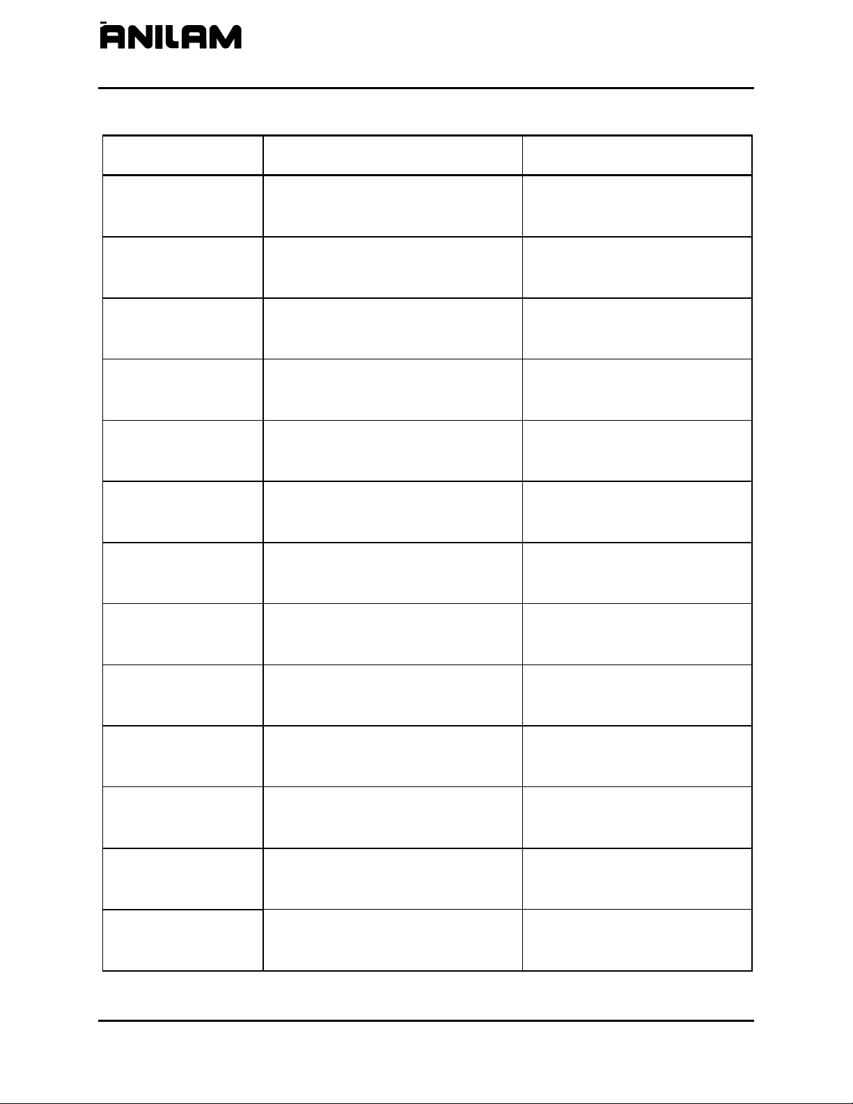
Effectivity Notation
Some sections of this manual apply only to specific ANILAM CNC
product(s). In these sections, icons in the left margin identify the
product(s) to which the information applies. Table 1-1 lists the icons for
each CNC product and the number of axes supported by each product.
Icon Product Axes Supported
6000M-3X
6300M
6000M-4X
6400M
NOTE: All systems also support one spindle axis.
The main difference between the products is the number of axes
supported. Generally, this manual describes the 6000M-3X systems.
The 6000M-4X operates exactly as the 6000M-3X system except for
features that include the additional axes.
There are many parameters that are defined per axis. In these cases,
this manual will document the primary axes (that is, XYZ). The
parameters for the auxiliary axis (that is, U) are entered in the same way
as those for the primary axes. Some parameters can also be specified
for the Spindle axis (that is, S).
Software Version Information
To facilitate verification of software version information, a text file is added
to all CNC machine and offline software disks. The file lists the version
and the CNC type. The software version contained on the disk is coded
into the filename using the following format
software version 4.14A is formatted as
containing software version
Table 1-1, CNC Effectivity Icon Description
6000M-3X Systems 3
6000M-4X Systems 4
: 0xxxx.txt. For example,
0414A.txt. Therefore, a disk
4.14A contains a file named 0414A.txt.
All rights reserved. Subject to change without notice.
10-December-04
1-1
Page 6
CNC Setup Utility Manual
P/N 70000490C - Setup Utility Concepts
Navigating Through the Setup Utility
The Setup Utility provides access to parameter settings through menus
and submenus. Each menu contains a list and a highlight. Highlight one
of the choices listed. Press
Each menu provides access to parameter settings or another menu.
ENTER to activate the highlighted choice.
Press
required. Press
the software. Press Exit (F10) to close a menu and return to the previous
menu.
Refer to “Section 6 - Setup Utility Maps
“Sections 1 – 4.” Use these maps to locate parameter settings. The
maps also serve as a quick reference guide.
NOTE: All dimensions, numbers, assigned values, and defaults
Default Settings
The Setup Utility has default settings pre-loaded in the configuration file.
These settings remain active unless you change them. In this manual,
default settings are specified as: [Default: Setting].
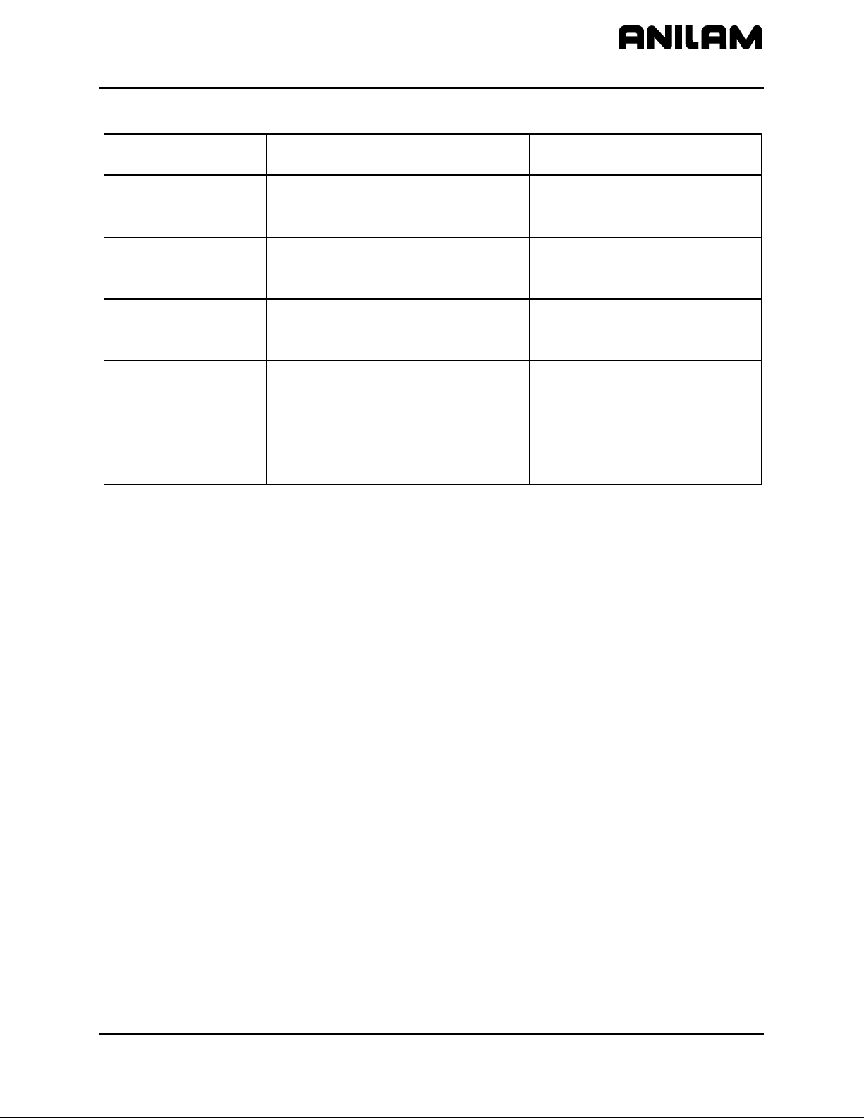
Keypad Keys
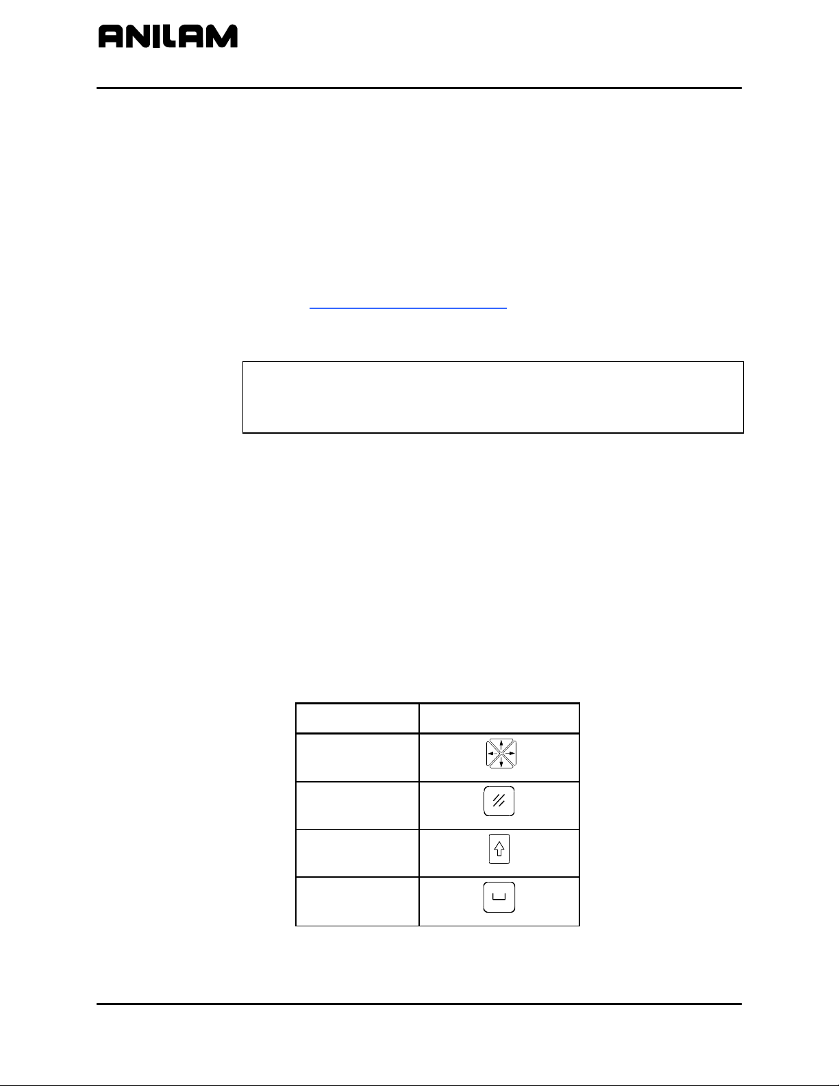
In this manual, the names ARROWS, CLEAR, SHIFT, and SPACE are
used for the corresponding keypad keys. See Table 1-2 for their
identifying key faces.
ENTER to toggle settings On or Off. Type a specific value where
ENTER or Exit (F10) to save settings when prompted by
” for all maps referenced in
provided in this manual are subject to change without notice
depending upon individual manufacturing considerations and
industry standards.
Additionally, the alphanumeric characters, (A – Z) and (0 – 9), are used to
reference corresponding alphanumeric keys.
Table 1-2, Keypad Keys
Name Key Face
ARROWS
CLEAR
SHIFT
SPACE
1-2
All rights reserved. Subject to change without notice.
10-December-04
Page 7

CNC Setup Utility Manual
P/N 70000490C - Setup Utility Concepts
Axis Keys
Some parameters require that you specify an axis. Use the X, Y, Z, or U
key to specify the axis.
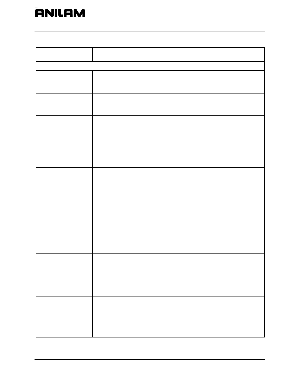
Console Switches/Manual Panel Keys
Console switches and Manual Panel Keys are referred to as shown in
Table 1-3.
Table 1-3, Console Switches/ Manual Panel Keys
Name Switch/Key
Y
Axis Selector Switch
Jog Selector Switch
Z
U
X
AXIS
FEED
RAPID
Feedrate OVERRIDE Switch
Spindle OVERRIDE Switch
E-Stop Key
Jog Plus Key
Jog Minus Key
Servo Reset Key
Start Key
Hold Key
SPINDLE
(Continued…)
All rights reserved. Subject to change without notice.
1-3
10-December-04
Page 8
CNC Setup Utility Manual
P/N 70000490C - Setup Utility Concepts
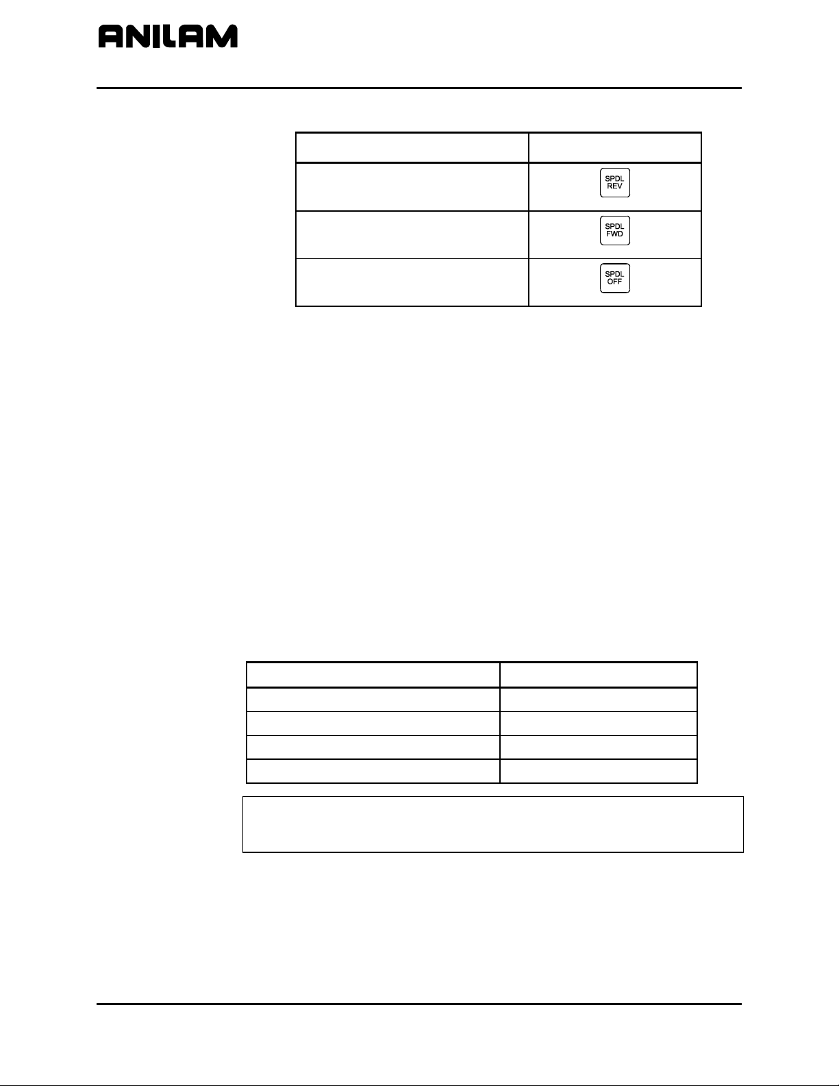
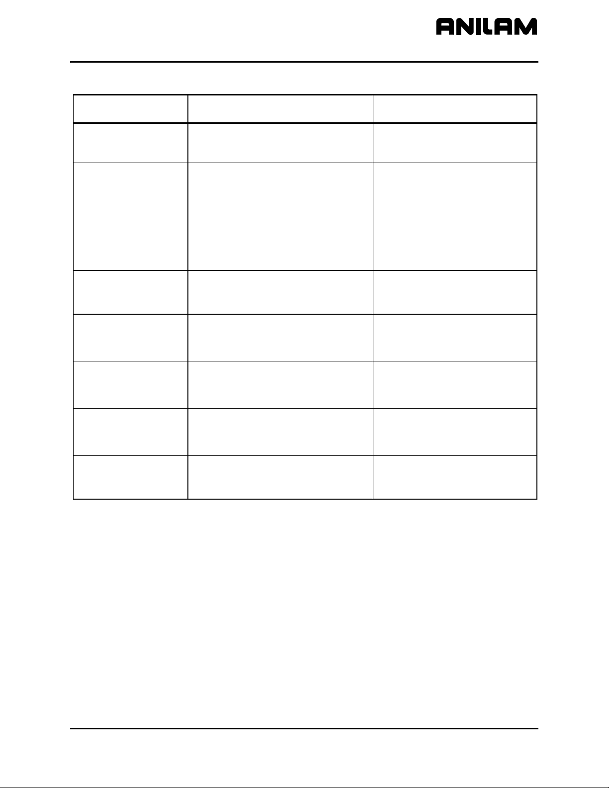
Table 1-3, Console Switches/ Manual Panel Keys (Continued)
Name Switch/Key
Spindle Reverse Key
Spindle Forward Key
Spindle Off Key
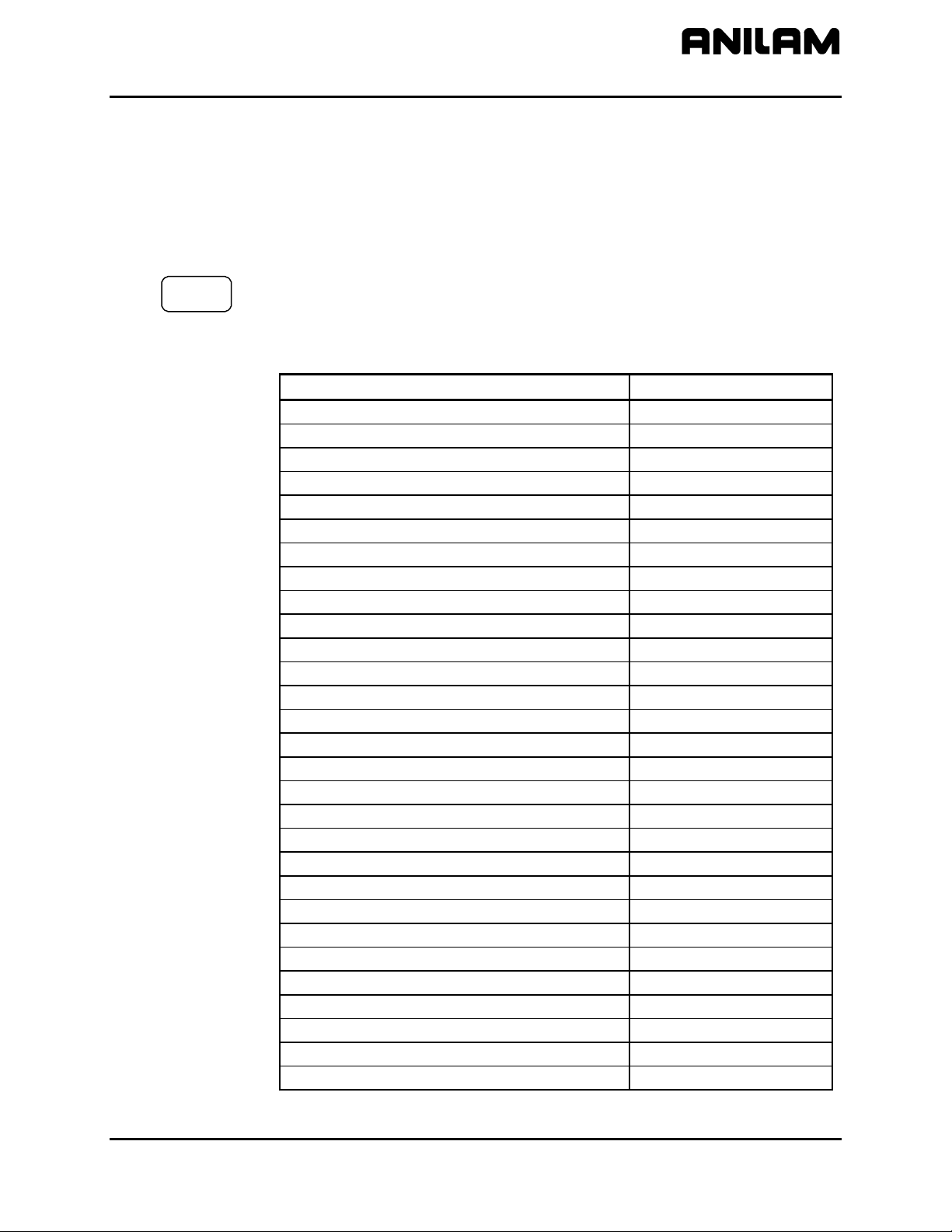
ENTER Key
Press
ENTER to enter parameters into the system.
Highlighting Menu Options
Press Up Arrow (F3
in the Setup Utility. The corresponding arrow keys can also be used.
Exiting a Screen
Press Exit (F10) to return to the previous screen.
Password Restricted Parameters
Some machine parameters are protected by passwords. The CNC
provides four access levels of passwords. Operators are assigned limited
access, which allows them to set parameters used in normal machine
operations. Service and factory technicians require a higher level of
access. The Programmable I/O Interface requires a separate password.
See Table 1-4 for default machine passwords.
Table 1-4, Default Machine Passwords
Access Level Password Level
Limited – Operator 159
Service Technician Z48
) and Down Arrow (F4) to highlight menu selections
Factory Technician Reserved for factory use
Programmable Logic Controller IPI
NOTE: Service supersedes Limited. Factory level is the highest and
supersedes all, except IPI, which is independent of the other
passwords.
1-4
All rights reserved. Subject to change without notice.
10-December-04
Page 9

CNC Setup Utility Manual
P/N 70000490C - Setup Utility Concepts
Changing Protected Parameters
To change protected parameters, enter a password when the CNC
displays the password prompt.
NOTE: You are only required to type a password once during Setup.
However, when you exit the Setup Utility and re-enter, you will
again be prompted for a password.
Saving Changes to Setup Parameters
When you exit the Setup Utility menu after you have changed any
parameters, the CNC displays the prompt “Save Changes?”.
Select one of the following:
Yes (F1) to save the changes.
No (F2) to cancel the changes.
Cancel (F9) to return to the Setup Utility Menu.
NOTE: When No (F2) is pressed, all parameters revert to the settings
prior to changes.
All configuration parameters are saved in a configuration file,
(P6MCFG.CFG). Every time a parameter is changed, the configuration
file is saved; the CNC automatically creates a backup file,
(P6MCFG.BAK). The CNC provides utilities to manage the configuration
file. Refer to “Section 4 - Configuration Utilities
Setting Parameters in Setup Utility
To set parameters in the Setup Utility, do the following:
1. Highlight the menu in which the parameter appears and press
Change the parameter by following one of the steps mentioned below:
In some cases a parameter can only have two selections. Pressing
ENTER changes from one value to the other.
In some cases, a parameter may have more than two selections and
pressing
Highlight the desired selection and press
In other cases, the CNC will highlight an entry field and you will be
allowed to type the value for the parameter. Type the desired value,
or setting, and press
ENTER will display a pop-up menu with the list of selections.
” for detailed information.
ENTER.
ENTER.
ENTER.
All rights reserved. Subject to change without notice.
10-December-04
1-5
Page 10

CNC Setup Utility Manual
P/N 70000490C - Setup Utility Concepts
Using Valid Parameter Ranges
All parameters entered in an entry field must be within the valid range for
the parameter. If the value entered is not within the valid range, an error
message is displayed. The error message shows the valid range for the
parameter. Pressing F10 or
the error message is cleared, you can enter another value. The previous
value can be restored by pressing
Accessing Setup Utility
To access the Setup Utility menus, do the following:
1. Turn on the CNC.
When the CNC is turned on, the CNC software starts automatically.
The CNC displays messages to indicate the status of the startup.
When the CNC software has successfully started, the CNC displays
ANILAM Company information and the software version number.
2. Press (F10) to continue.
CLEAR can clear the error message. Once
UP ARROW and then ENTER.
3. Use the ARROW keys to highlight Setup
If already in Manual mode, access the Software Options screen by
pressing SHIFT + F10. The servos must be off or the CNC will not allow
you to exit Manual mode.
In either case, the CNC displays the Setup
Map 1
Units of Measurement
The Units of Measurement parameter specifies the units used to enter
dimensional data. If you are using mixed data, input data in one format
(inch or mm) first. Change the format (inch or mm) and enter the rest of
the data. You can change the units as many times as you need to. By
using the proper units you do not need to convert values, but can enter
data precisely (that is, no rounding during conversion). See MC_1002:
Default units. [Default: Inch]
All dimensional data will be displayed according to the units specified in
this parameter.
6400M
6000M-4X
The only exception to this rule is the dimensional parameter
corresponding to rotary axes. If the auxiliary axis (that is, U) is configured
as a rotary axis, then the unit is always in degrees or degrees per minute
(that is, deg/min).
The CNC displays the Software Options screen.
Utility. Press ENTER.
Options Menu. Refer to
, Menu A. This menu allows you to access the setup parameters.
1-6
All rights reserved. Subject to change without notice.
10-December-04
Page 11
CNC Setup Utility Manual
P/N 70000490C - Machine Constants
Section 2 - Machine Constants
The Machine Constants configures the settings for the CNC.
Machine Constants Group Assignments
Refer to Table 2-1 for range assignments.
6400M
6000M-4X
The Setup Utility displays Machine Constants for axes X, Y, Z, and U.
Machine Constants for the U-axis need to be set when the U-axis is
used in a 6000M-4X.
Table 2-1, Machine Constant Group Assignments
Setup Parameter Group MC Range
Control Software MC_1000 – MC_1099
Draw Mode MC_1100 – MC_1199
User Definable Variables MC_1120 – MC_1149
Tool Probe Variables MC_1150 – MC_1199
Editor Mode MC_1200 – MC_1299
Program Directory MC_1300 – MC_1349
RS-232 Communication MC_1350 – MC_1374
Printer MC_1375 – MC_1399
X-axis Setup MC_2000 – MC_2099
Y-axis Setup MC_2100 – MC_2199
Z-axis Setup MC_2200 – MC_2299
U-axis Setup MC_2300 – MC_2399
Spindle axis Setup MC_2900 – MC_2999
Linear Correction Compensation MC_3000 – MC_3014
Skew Error Compensation MC_3015 – MC_3029
Backlash Compensation MC_3030 – MC_3049
Ballscrew Compensation MC_3050 – MC_3099
Software Limits MC_4000 – MC_4019
Continuous Path MC_4020 – MC_4029
Position Error Check (PEC) MC_4030 – MC_4049
Jog Return Position MC_4050 – MC_4059
Direct Numeric Control (DNC) MC_4060 – MC_4065
Handwheel MC_4100 – MC_4149
Home MC_4200 – MC_4249
Miscellaneous MC_4300 – MC_4399
M-Code Macro Call MC_4400 – MC_4419
Tool Management MC_5000 – MC_5099
Interface MC_5100 – MC_5149
More Parameters MC_5200 – MC_5299
All rights reserved. Subject to change without notice.
10-December-04
2-1
Page 12

P/N 70000490C - Machine Constants
CNC Setup Utility Manual
Machine Constants Setup
Refer to Table 2-2 for the parameter descriptions and setting information.
The table has subheadings to help you identify the parameters; these
subheadings do not display in the software or the Off-line. The default
value in Table 2-2 is bold where there are multiple selections available.
NOTE: Press
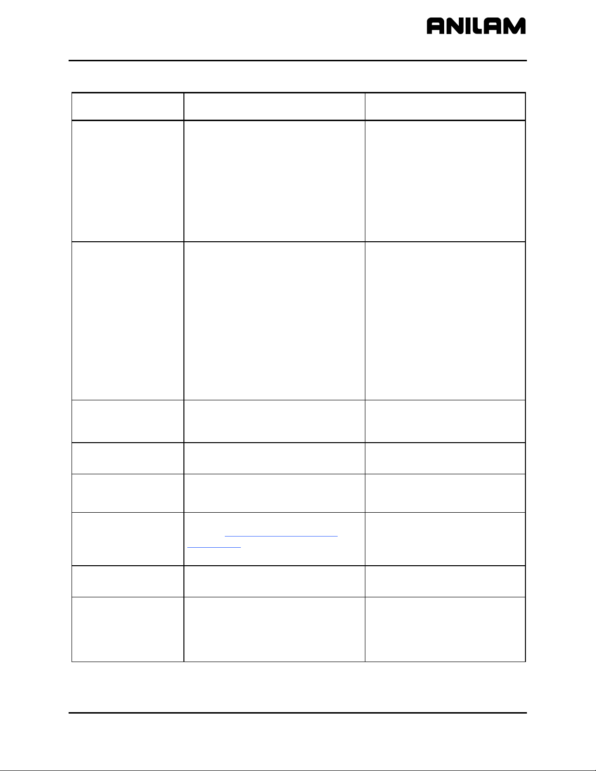
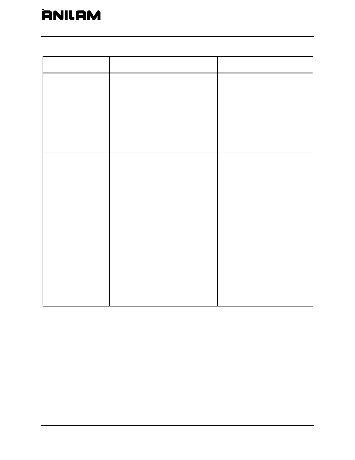
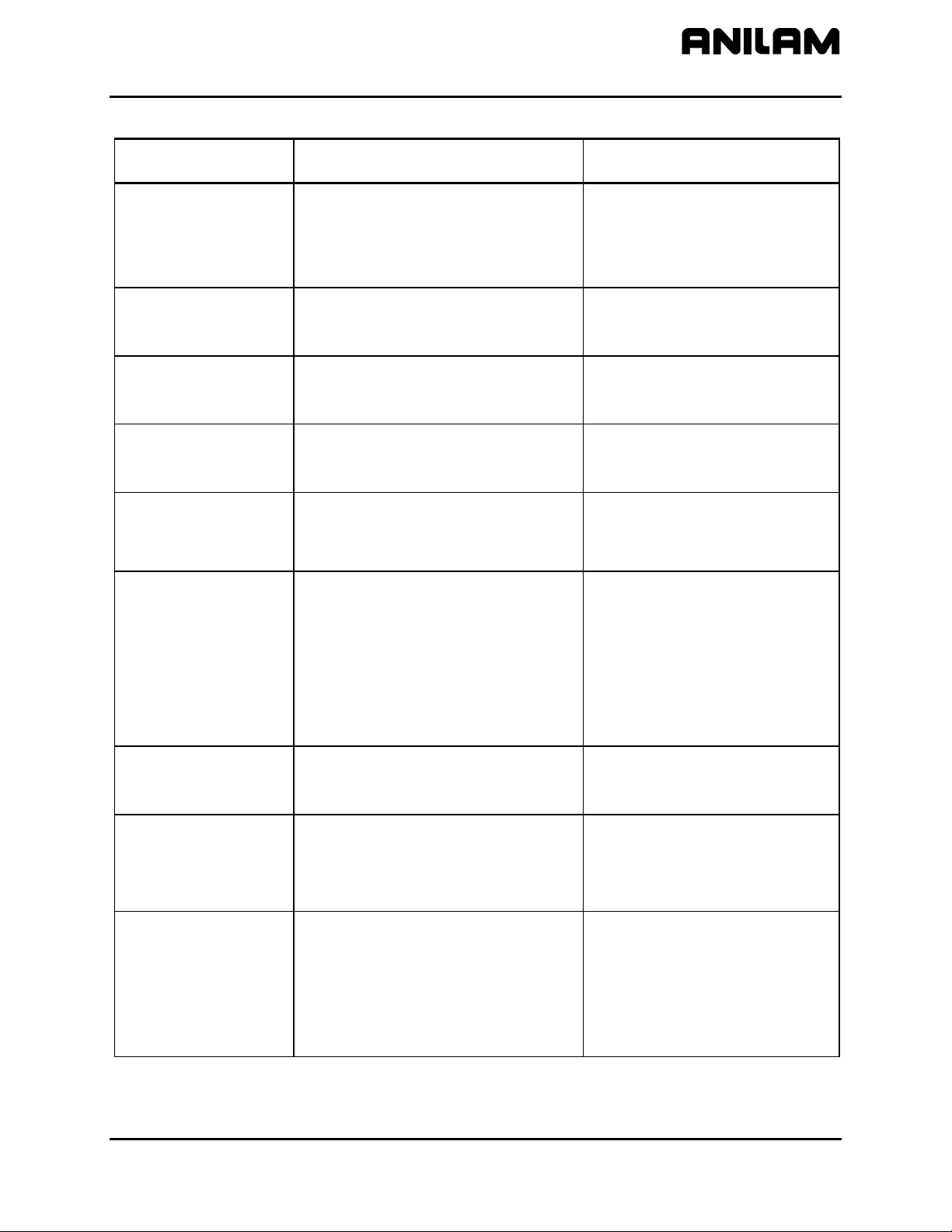
Table 2-2, Machine Constants Setup
Machine Constant
Parameter
MC_1000:
Default axis display
MC_1001:
Default plane
MC_1002:
Default units
MC_1003:
Default axis values
Function Settings
Control Software Setup Parameters
Switches the default axis display
between large and normal.
A plane defines movement along two
axes, excluding a third. Thus, planar
movement is two-dimensional. Circular
moves and tool diameter compensation
are confined to the plane chosen by the
user. (Linear moves can occur in all
three axes simultaneously.).
Switches the default measurement units
(Inch/MM Modes).
Switches Absolute/ Incremental default
mode (determines how axis values for
arcs, lines, and other moves are
measured).
ENTER to toggle the available settings.
Large - Configures the axis display
to show enlarged X, Y, Z, and
U Program position display
only.
Normal - Configures the axis
display to show Machine,
Program, Target, and
Distance To Go displays.
[Default]
XY - (top view) displays program in
X and Y. [Default]
XZ - displays program in X and Z.
YZ - displays program in Y and Z.
Inch – Activates Inch Mode as
default. [Default]
MM – Activates MM (millimeter)
Mode as default.
Absolute – Makes every move in
reference to an Absolute Zero
position (Program Zero or Part
Zero). [Default]
Incremental – Makes each move in
reference to the last
programmed endpoint.
(Continued…)
2-2 All rights reserved. Subject to change without notice.
10-December-04
Page 13
CNC Setup Utility Manual
P/N 70000490C - Machine Constants
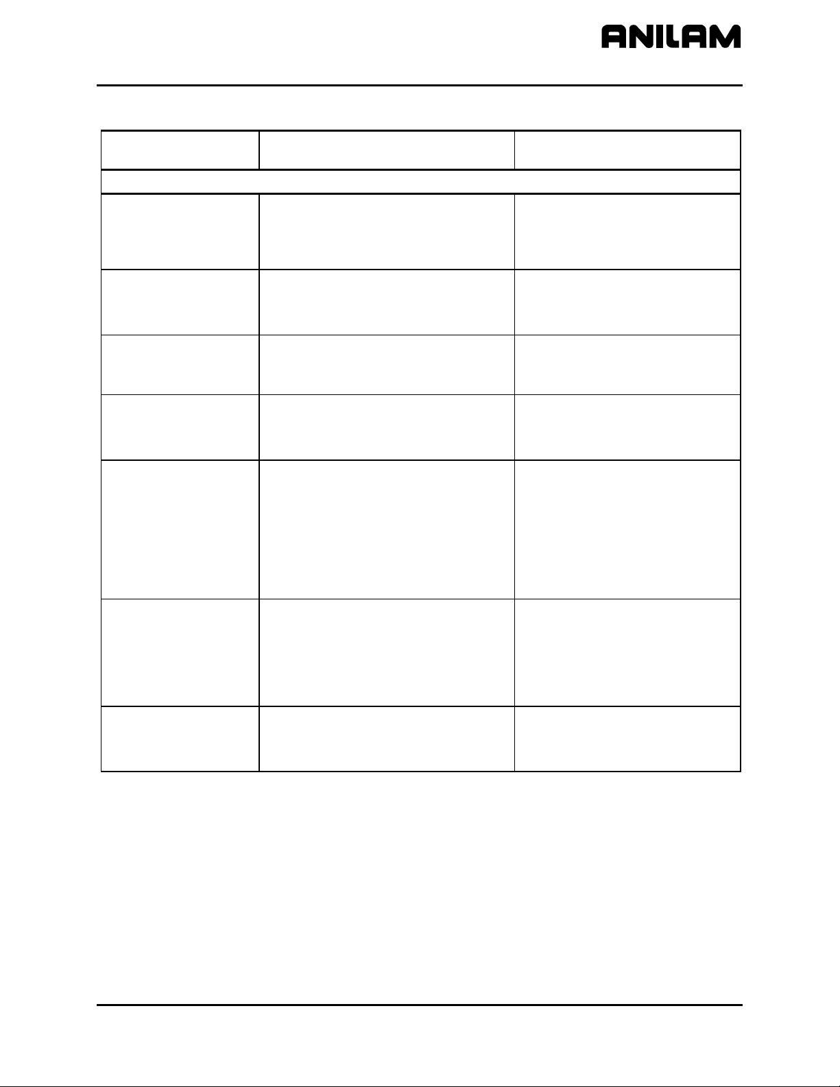
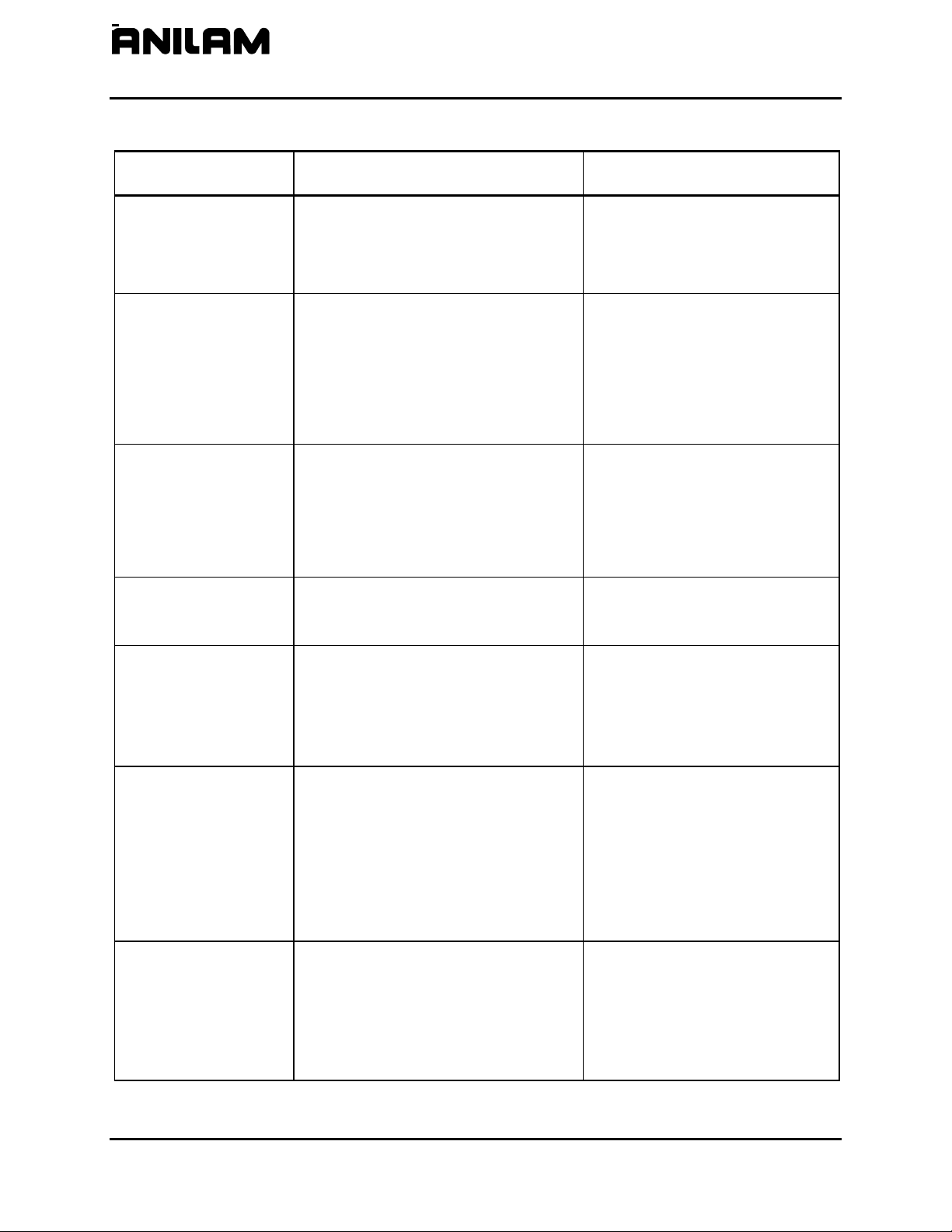
Table 2-2, Machine Constants Setup (Continued)
Machine Constant
Parameter
MC_1004:
Circle adjustments
MC_1005:
Circle centers
MC_1006:
Maximum arc
correction
MC_1007:
Internal accuracy
MC_1008:
External accuracy
MC_1009:
Compensation cutoff
angle
MC_1011:
User macro file
MC_1012:
Load user macro file
Function Settings
Specifies whether circle centers or
endpoints will be adjusted. Circle
centers require adjustment when the
CNC encounters incorrect circle center
or end-point coordinates.
Center - Adjusts the position of the
circle center when the CNC
encounters incorrect
coordinates for either a circle
center or endpoint.
End-Point - Adjusts the position of
the circle endpoint when the
CNC encounters incorrect
coordinates for either a circle
center or end-point. [Default]
Switches the default mode for
programmed circle center coordinates.
Absolute - CNC interprets
programmed circle center
coordinates as Absolute
values.
Incremental - CNC interprets
programmed circle center
coordinates as Incremental
values. [Default]
Modal - CNC interprets
programmed circle center
coordinates based on current
Incremental or Absolute
setting.
Specifies the maximum amount of
correction the CNC will apply to an arc
block before declaring an error.
Maximum accuracy available (system
resolution).
Specifies the maximum system
accuracy obtainable on a given machine
(machine resolution).
Minimizes wasted travel on acute angle.
Refer to Figure 2-1, Compensation
Cutoff Angle.
Range (0.000000–1.000000)
0.005000 [Default]
Range (0.00000001–0.00100000)
0.00000100 [Default]
Range (0.00000001–0.00100000)
0.00010000 [Default]
Range (1.0–90.0)
15.0 (degrees) [Default]
Specifies macro filename created by
USERCANN.G [Default]
user.
Specifies whether to load user macro at
system startup.
No - Does not automatically load
user macro at startup.
[Default]
Yes - Automatically loads user
macro at startup.
(Continued…)
All rights reserved. Subject to change without notice.
10-December-04
2-3
Page 14
P/N 70000490C - Machine Constants
CNC Setup Utility Manual
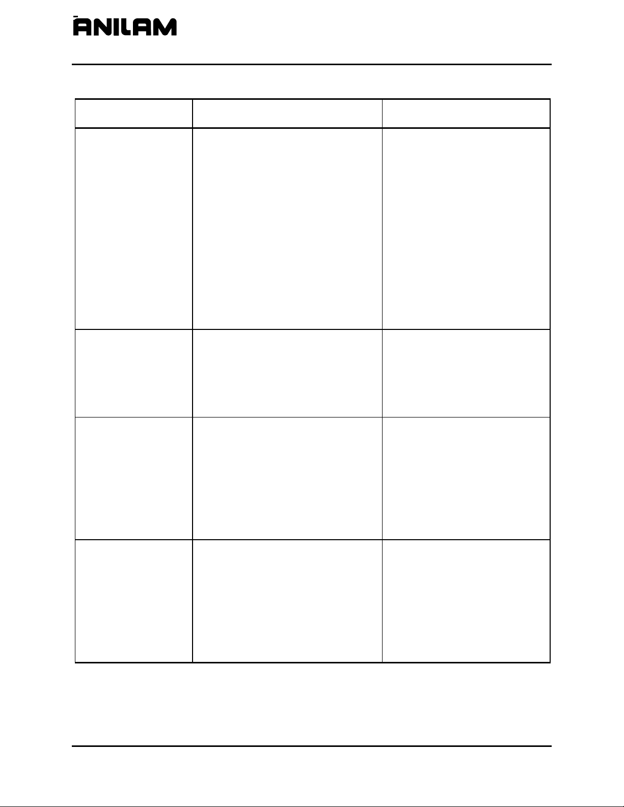
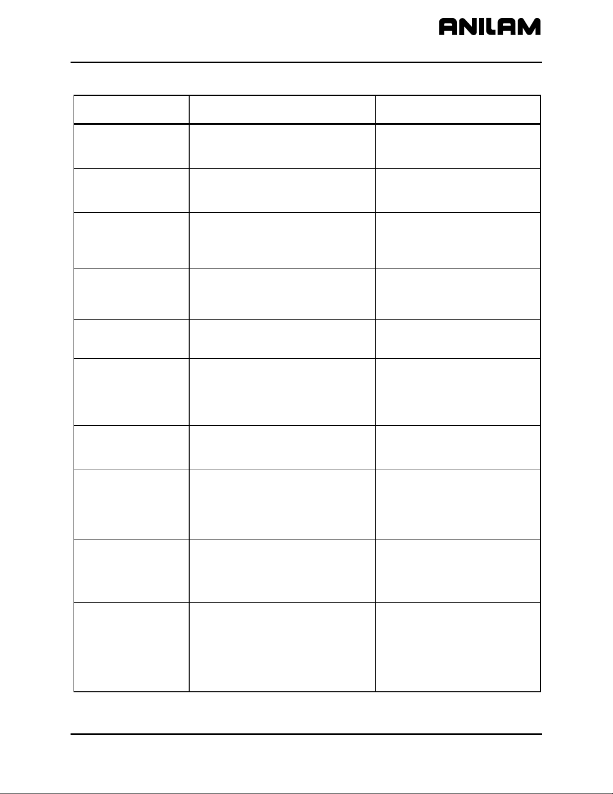
Table 2-2, Machine Constants Setup (Continued)
Machine Constant
Parameter
MC_1013:
Disk access marker
MC_1014:
Max. memory
allocated
(in MB-bytes)
MC_1015:
Force simulation
mode
MC_1016:
Screen blanking delay
(minutes)
MC_1032:
Enable radius
compensation error
checking
Function Settings
Activates/deactivates the Disk access
marker.
On - Activates the Disk access
marker. When the CNC is
reading/writing information
from/to a disk the Disk access
marker is displayed in the
upper-left corner of the
screen. The Disk access
marker looks like a small
arrow. [Default]
Off - Deactivates Disk access
marker.
Used only with off-line software. Limits
the amount of memory available to the
software. This parameter is used to limit
Range (2–128)
4 (MB) [Default]
the amount of memory available in
multitasking environments that provide
virtual memory.
In Simulation Mode, the CNC does not
generate motor and I/O signals. The
CNC starts in Simulation Mode. Moves
can be commanded and displayed, but
Yes - Enable [Default]
No - Disable
no actual machine movements occur.
Specifies the screen blanking delay
period, in minutes. The delay will be the
time between a detected screen idle
Range (0–20160)
5 (minutes) [Default]
condition and the activation of the
screen saver. To reactivate, press any
key.
Activates the tool radius compensation
error checking. The error checking is
designed to eliminate simple gouges
Yes - Enable
No – Disable [Default]
caused by overcompensation.
(Continued…)
2-4 All rights reserved. Subject to change without notice.
10-December-04
Page 15
CNC Setup Utility Manual
P/N 70000490C - Machine Constants
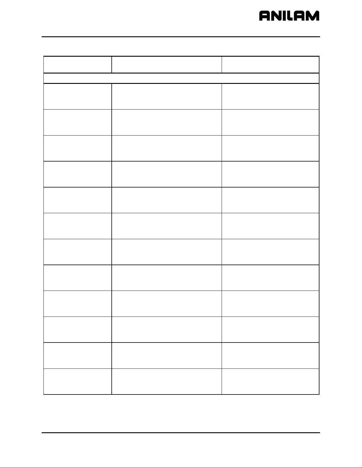
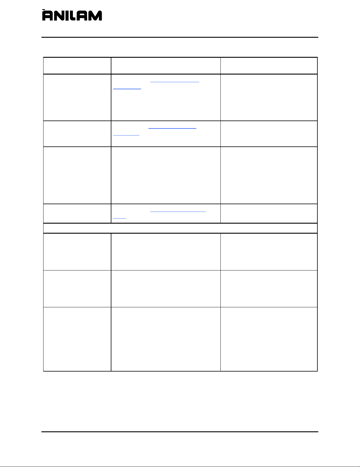
Table 2-2, Machine Constants Setup (Continued)
Machine Constant
Parameter
MC_1100:
Restore Draw to
previous session
MC_1101:
Default program block
mode
MC_1102:
Display program text
MC_1103:
Grid
MC_1104:
Grid size
MC_1105:
Tool display
MC_1106:
Default tool type
Function Settings
Draw Mode Setup Parameters
Sets the CNC to re-activate the last
active session when you re-enter Draw.
Yes - CNC re-activates last
session when Draw activated.
[Default]
No - CNC ignores parameter.
Sets default mode in Draw.
Auto [Default]
S.Step
Motion
Determines whether program text is
displayed in Draw Mode.
Yes - Shows program text.
[Default]
No - Does not show program text.
Activates/deactivates grid as a dotted or
solid line.
None - Deactivates grid. [Default]
Solid - Activates solid line grid.
Dotted - Activates dotted line grid.
Determines the size of the grid (in the
active Inch or MM Mode).
NOTE: The CNC converts the set grid
value if the measurement unit is
changed. For example: if the Grid Size
is set for 1 in Inch Mode and you switch
to MM Mode, the CNC changes the Grid
Range (0.0–25,400.0)
1.0 [Default]
(If the CNC is in Inch Mode, each
square in the grid will be one
square inch in size for this setting.)
Size to 25.4 mm (equal to 1 inch).
Turns the tool display On and Off.
On - The tool (as defined by the
Tool Location Code and
Radius in the Tool Page) will
be displayed as it cuts the
workpiece. [Default]
Off - No tool is displayed.
Determines shape of displayed tool. None - No tool shown
Flat - Flat-end tool shown [Default]
Ball - Ball-end tool shown
(Continued…)
All rights reserved. Subject to change without notice.
10-December-04
2-5
Page 16
P/N 70000490C - Machine Constants
CNC Setup Utility Manual
Table 2-2, Machine Constants Setup (Continued)
Machine Constant
Parameter
MC_1107:
Cutter compensation
in Draw
MC_1108:
Draw view
MC_1109:
Aspect ratio
correction factor
MC_1110:
Save/Restore Draw
image when using
Edit
Function Settings
Activates/deactivates cutter
compensation in Draw Modes.
Ignore - CNC will not show
compensated moves (if any)
used in the program.
Use - CNC shows compensated
and non-compensated
programmed moves.
Both - CNC runs the program
twice. First, the program is
run without compensated
moves. Second, the program
is run showing compensated
moves. This provides a
comparison of the two paths
to determine programming
errors related to
compensation. [Default]
Determines perspective of Draw view.
XY - (top view) displays program in
X and Y. [Default]
XZ - displays program in X and Z.
YZ - displays program in Y and Z.
ISO - displays program in X, Y,
and Z.
Corrects circularity problems with
display of circles and drawings in
general. In cases where a circle may
Range (0.01–10.00)
1.47 [Default]
look distorted (that is, like an egg), this
parameter can be used to make the
circle look like a TRUE circle.
Increasing the number will make the
circle taller and skinnier; decreasing the
number will make the circle shorter and
fatter.
Saves draw image when user switches
to Edit Mode. In Draw Mode, when the
Edit (F2) soft key is pressed, the CNC
Yes - Saves draw image. [Default]
No - Does not save draw image.
switches to Edit Mode. The user later
re-enters the Draw Mode when you exit
Edit Mode. If this option is enabled
(Yes), the CNC restores the image on
the screen prior to entering Edit. This
image will correspond to the part
program drawing.
(Continued…)
2-6 All rights reserved. Subject to change without notice.
10-December-04
Page 17
CNC Setup Utility Manual
P/N 70000490C - Machine Constants
Table 2-2, Machine Constants Setup (Continued)
Machine Constant
Parameter
MC_1120:
User definable
variable #1120
MC_1121:
User definable
variable #1121
MC_1122:
User definable
variable #1122
MC_1123:
User definable
variable #1123
MC_1124:
User definable
variable #1124
MC_1125:
User definable
variable #1125
MC_1126:
User definable
variable #1126
MC_1127:
User definable
variable #1127
MC_1128:
User definable
variable #1128
MC_1129:
User definable
variable #1129
MC_1130:
User definable
variable #1130
MC_1131:
User definable
variable #1131
Function Settings
User Definable Variables Setup Parameters
Variable defined by user to be used in
general CNC programming.
Range (-99999–99999)
0 [Default]
Integer value: 0 to 99999
Variable defined by user to be used in
general CNC programming.
Range (-99999–99999)
0 [Default]
Integer value: 0 to 99999
Variable defined by user to be used in
general CNC programming.
Range (-99999–99999)
0 [Default]
Integer value: 0 to 99999
Variable defined by user to be used in
general CNC programming.
Range (-99999–99999)
0 [Default]
Integer value: 0 to 99999
Variable defined by user to be used in
general CNC programming.
Range (-99999–99999)
0 [Default]
Integer value: 0 to 99999
Variable defined by user to be used in
general CNC programming.
Range (-99999–99999)
0 [Default]
Integer value: 0 to 99999
Variable defined by user to be used in
general CNC programming.
Range (-99999–99999)
0 [Default]
Integer value: 0 to 99999
Variable defined by user to be used in
general CNC programming.
Range (-99999–99999)
0 [Default]
Integer value: 0 to 99999
Variable defined by user to be used in
general CNC programming.
Range (-99999–99999)
0 [Default]
Integer value: 0 to 99999
Variable defined by user to be used in
general CNC programming.
Range (-99999–99999)
0 [Default]
Integer value: 0 to 99999
Variable defined by user to be used in
general CNC programming.
Range (-25000.0000–25000.0000)
0.0000 [Default]
Unit based (Inch or MM).
Variable defined by user to be used in
general CNC programming.
Range (-25000.0000–25000.0000)
0.0000 [Default]
Unit based (Inch or MM).
(Continued…)
All rights reserved. Subject to change without notice.
10-December-04
2-7
Page 18
P/N 70000490C - Machine Constants
CNC Setup Utility Manual
Table 2-2, Machine Constants Setup (Continued)
Machine Constant
Parameter
MC_1132:
User definable
variable #1132
MC_1133:
User definable
variable #1133
MC_1134:
User definable
variable #1134
MC_1135:
User definable
variable #1135
MC_1136:
User definable
variable #1136
MC_1137:
User definable
variable #1137
MC_1138:
User definable
variable #1138
MC_1139:
User definable
variable #1139
MC_1140:
User definable
variable #1140
MC_1141:
User definable
variable #1141
MC_1142:
User definable
variable #1142
MC_1143:
User definable
variable #1143
MC_1144:
User definable
variable #1144
Function Settings
Variable defined by user to be used in
general CNC programming.
Range (-25000.0000–25000.0000)
0.0000 [Default]
Unit based (Inch or MM).
Variable defined by user to be used in
general CNC programming.
Range (-25000.0000–25000.0000)
0.0000 [Default]
Unit based (Inch or MM).
Variable defined by user to be used in
general CNC programming.
Range (-25000.0000–25000.0000)
0.0000 [Default]
Unit based (Inch or MM).
Variable defined by user to be used in
general CNC programming.
Range (-25000.0000–25000.0000)
0.0000 [Default]
Unit based (Inch or MM).
Variable defined by user to be used in
general CNC programming.
Range (-99999.0000–99999.0000)
0.0000 [Default]
No units assigned.
Variable defined by user to be used in
general CNC programming.
Range (-99999.0000–99999.0000)
0.0000 [Default]
No units assigned.
Variable defined by user to be used in
general CNC programming.
Range (-99999.0000–99999.0000)
0.0000 [Default]
No units assigned.
Variable defined by user to be used in
general CNC programming.
Range (-99999.0000–99999.0000)
0.0000 [Default]
No units assigned.
Variable defined by user to be used in
general CNC programming.
Range (-25000.0000–25000.0000)
0.0000 [Default]
Unit based (Inch or MM).
Variable defined by user to be used in
general CNC programming.
Range (-25000.0000–25000.0000)
0.0000 [Default]
Unit based (Inch or MM).
Variable defined by user to be used in
general CNC programming.
Range (-25000.0000–25000.0000)
0.0000 [Default]
Unit based (Inch or MM).
Variable defined by user to be used in
general CNC programming.
Range (-25000.0000–25000.0000)
0.0000 [Default]
Unit based (Inch or MM).
Variable defined by user to be used in
general CNC programming.
Range (-25000.0000–25000.0000)
0.0000 [Default]
Unit based (Inch or MM).
2-8 All rights reserved. Subject to change without notice.
10-December-04
Page 19
CNC Setup Utility Manual
P/N 70000490C - Machine Constants
Table 2-2, Machine Constants Setup (Continued)
Machine Constant
Parameter
MC_1145:
User definable
variable #1145
MC_1146:
User definable
variable #1146
MC_1147:
User definable
variable #1147
MC_1148:
User definable
variable #1148
MC_1149:
User definable
variable #1149
(Continued…)
Function Settings
Variable defined by user to be used in
general CNC programming.
Range (-25000.0000–25000.0000)
0.0000 [Default]
Unit based (Inch or MM).
Variable defined by user to be used in
general CNC programming.
Range (-25000.0000–25000.0000)
0.0000 [Default]
Unit based (Inch or MM).
Variable defined by user to be used in
general CNC programming.
Range (-25000.0000–25000.0000)
0.0000 [Default]
Unit based (Inch or MM).
Variable defined by user to be used in
general CNC programming.
Range (-25000.0000–25000.0000)
0.0000 [Default]
Unit based (Inch or MM).
Variable defined by user to be used in
general CNC programming.
Range (-25000.0000–25000.0000)
0.0000 [Default]
Unit based (Inch or MM).
All rights reserved. Subject to change without notice.
10-December-04
2-9
Page 20
P/N 70000490C - Machine Constants
CNC Setup Utility Manual
Table 2-2, Machine Constants Setup (Continued)
Machine Constant
Parameter
MC_1150:
3-D probe type
MC_1151:
Nominal probe stylus
diameter
MC_1152:
Maximum stroke from
home for first pick
MC_1153:
RPM for calibration
and tool measurement
MC_1154:
Probe orientation
MC_1155:
Z first pick, FAST
feed-rate
MC_1156:
Z first pick, MEDIUM
feed-rate
MC_1157:
Z first pick, SLOW
feed-rate
MC_1158:
Z retract amount
Function Settings
Tool Probe Variables Setup Parameters
Transmission type used for the installed
3-D touch probe.
Corded [Default]
Cordless
The overall nominal probe stylus
diameter.
The distance from machine Z home with
the shortest tool or the spindle face to
just below the probe stylus top as the
Range (0.0000–51.0000)
0.0000 [Default]
Range (0.0000–999.0000)
0.0000 [Default]
maximum stroke for the initial probe
pick.
The spindle spin RPM for tool touch. Range (100–1000)
0 (rev/min) [Default]
Sets the probe orientation. Range (-2–2)
1 Probe is pointing to the right as
you are facing the machine in
the +X direction.
-1 Probe is pointing to the left of
the machine in the -X direction.
0 [Default]
2 Probe is pointing away from
you, toward the back of the
machine in the +Y direction.
-2 Probe is pointing toward you,
toward the front of the machine
in the –Y direction.
Sets user definable FAST feed-rate. Range (2.5–2540.0)
0.0 [Default]
Sets user definable MEDIUM feed-rate. Range (2.5–508.0)
0.0 [Default]
Sets user definable SLOW feed-rate. Range (0.1–254.0)
0.0 [Default]
Sets user definable distance the tool will
back away on the Z-axis after it touches
the probe.
Range (0.0100–25.400)
0.0000 [Default]
(Continued…)
2-10 All rights reserved. Subject to change without notice.
10-December-04
Page 21
CNC Setup Utility Manual
P/N 70000490C - Machine Constants
Table 2-2, Machine Constants Setup (Continued)
Machine Constant
Parameter
MC_1159:
XY retract amount
MC_1160:
Z rapid to start
position from home
MC_1161:
Diameter of tool probe
gauge
MC_1162:
Positioning feedrate
normally
MC_1163:
First touch feedrate
MC_1164:
Nominal probe stylus
ball radius
MC_1165:
Diameter of spindle
probe gauge
Function Settings
Sets user definable distance the tool will
back away on the X-axis or Y-axis after
it touches the probe.
Set the longest tool in the spindle and
bring the Z-axis to machine home. With
a tape measure, measure the distance
Range (0.0100–25.400)
0.0000 [Default]
Range (0.0000–999.0000)
0.0000 [Default]
from the tool tip to within 0.5” (12.7 mm)
above the top of the probe stylus and
enter that number. When using G151,
this will cause the tool to rapid to this
position in the Z-axis before starting the
initial probe touch in the Z-axis.
Sets the probe calibration standard
diameter.
Feedrate used for positioning the probe
in protected mode.
Typical value: 200 inches/minute (IPM).
Feedrate used for positioning for the
initial pick.
Typical value: 50 inches/minute (IPM).
Diameter of the probe stylus divided by
2.
Range (0.1000–508.0000)
0.0000 [Default]
Range (0.1–25400.0)
0.0 [Default]
Range (0.1–2540.0)
0.0 [Default]
Range (0.0100–25.4000)
0.0000 [Default]
The exact diameter of the ring gauge
used for probe calibration.
Range (0.1000–508.0000)
0.0000 [Default]
(Continued…)
All rights reserved. Subject to change without notice.
10-December-04
2-11
Page 22
P/N 70000490C - Machine Constants
CNC Setup Utility Manual
Table 2-2, Machine Constants Setup (Continued)
Machine Constant
Parameter
MC_1200:
Restore Editor to
previous session
MC_1201:
Show top line
MC_1202:
Default insert mode
MC_1203:
Auto tab to previous
line’s position
MC_1205:
Default tab width
MC_1206:
Create backup
program
Function Settings
Editor Mode Setup Parameters
If Yes (enabled), when user exits a
program in Edit Mode, the CNC marks
the position where the last edit was
made. The next time the program is
opened, the cursor will be located at
Yes - restores to previous session.
[Default]
No - does not restore to previous
session.
that spot.
Determines whether an optional “top
line” will be displayed in the Edit Mode.
The top line contains the active mode
Yes - Displays top line. [Default]
No - Does not display top line.
information and first block of the open
program.
Switches On/Off Default Insert Mode.
Insert Mode inserts new text without
overwriting existing text.
On - Automatically sets Insert
Mode as default. [Default]
Off - Does not automatically set
Insert Mode as default.
This option is available only with off-line
systems or systems with attached
keyboards. When a line is indented, the
CNC uses the indented position as the
first tab position of the following line.
Yes - Enables auto tab to previous
line’s position. [Default]
No - Disables auto tab to previous
line’s position.
For example, the user indents one line
by four spaces and then moves to the
beginning of the next line by pressing
ENTER. When you press TAB, the cursor
now advances four spaces.
This option is available only with offline
systems or systems with keyboards
attached.
Range (2–16)
4 (spaces) [Default]
Sets default tab width. Range is 2 to 16
spaces. When you press
TAB, the
cursor advances by the specified
number of spaces.
A backup program is created when an
edit is made. Each time the program is
edited, the CNC updates the backup
file. The backup program will not
contain an edit until a new edit is made.
Yes - Backup program is created
and maintained.
No - No backup programs are
created. [Default]
(Continued…)
2-12 All rights reserved. Subject to change without notice.
10-December-04
Page 23
CNC Setup Utility Manual
P/N 70000490C - Machine Constants
Table 2-2, Machine Constants Setup (Continued)
Machine Constant
Parameter
MC_1208:
Case sensitive Find
MC_1209:
Memory reserved from
editor (in K-bytes)
MC_1300:
Program directory
pattern
MC_1301:
Program directory
display mode
MC_1302:
Program directory
sort order
MC_1303:
Automatically check
disk at startup
MC_1304:
Delete backup files
during optimize
MC_1305:
Directory for user
program
Function Settings
Determines whether the Find feature
will search for uppercase and lowercase
letters to determine a match.
Yes - Find search parameter looks
for words that exactly match
the entered word specific to
capitalization and style.
No - Find search parameter looks
for the entered word,
regardless of capitalization
and style. [Default]
Specifies the amount of memory that
the editor will not allocate (that is,
leaving free).
Range (16–32000)
300 (KB) [Default]
Program Directory Setup Parameters
Type of programs displayed.
*.G+*.M [Default]
Plus sign ‘+’ can be used to specify
multiple types.
Specifies what program information will
be displayed in the Program Directory.
Short - Filename and extension
only [Default]
Long - Detailed program
information, including file size,
etc.
Specifies the order in which programs
are listed in the Program Directory.
Ignore - CNC ignores parameter.
Name - Alphanumeric order by
filename [Default]
Extension - Alphanumeric order by
file extension
Size - By file size
Date - By date program was
created
For machines equipped with hard
drives, specifies whether and how often
CNC will check the hard drive.
Always
Daily
Weekly
Monthly [Default]
Never
For machines equipped with hard
drives, specifies whether backup files
will be deleted during hard drive
optimization.
CNC will store user programs in
specified directory.
Yes - Backup files deleted during
optimization process [Default]
No - Backup files maintained
during optimization process
C:\USER [Default]
Enter user directory location
(Continued…)
All rights reserved. Subject to change without notice.
10-December-04
2-13
Page 24
P/N 70000490C - Machine Constants
CNC Setup Utility Manual
Table 2-2, Machine Constants Setup (Continued)
Machine Constant
Parameter
MC_1350: Port
MC_1351: Baud
MC_1352: Parity
MC_1353:
Data bits
MC_1354:
Stop bits
MC_1355:
Software
MC_1375:
Default output device
MC_1376:
Lines per page
MC_1377:
Page heading
MC_1378:
Line numbers
MC_1381:
Wrap text
Function Settings
RS-232 Communication Setup Parameters
Selects a communications port or
disables. Must enable for remote
communications.
COM1, COM2, Disabled
[Default: Disabled]
Selects a baud. 110, 150, 300, 600, 1200, 2400,
4800, 9600 [Default], or 19200
Selects parity.
Enters number of data bits.
NONE, ODD, or EVEN [Default]
7 [Default]
8
Enters number of stop bits. 0
1 [Default]
Refers to Xon or Xoff or “handshaking”
(transmission/ receipt of data via
RS-232) in communications packages.
Printer Setup Parameters
On - Enables handshaking
[Default]
Off - Disables handshaking
Specifies where file will be printed. PRN [Default]
To print to another file, enter drive,
path, and filename with extension.
If the filename entered is not an
existing file, the CNC creates the
file and transfers the data to the
file. If the filename entered is an
existing file, the CNC overwrites
the data in the file with the print file
data.
Number of lines to be printed per page
(8.5 X 11”).
Range (1–66)
55 [Default]
Enter desired value
Prints a page heading including
filename, date and time, and page
number.
Yes - Prints heading. [Default]
No - Does not print heading
Prints line numbers on hard copy of file. Yes - Prints line numbers
No - Select No if no line numbers
are desired [Default]
Wraps text to the next line if program is
greater than 80 characters.
Yes - Wraps text [Default]
No - Truncates text
(Continued…)
2-14 All rights reserved. Subject to change without notice.
10-December-04
Page 25

CNC Setup Utility Manual
P/N 70000490C - Machine Constants
Table 2-2, Machine Constants Setup (Continued)
Machine Constant
Parameter
MC_2000:
X Motor Encoder
Connector
MC_2001:
X PWM Output
Connector
MC_2002:
X Inverter Type
MC_2003:
X Motor Type
Function Settings
X-axis Setup Parameters
The connection to which the motor
encoder for the X-axis is connected.
X15 [Default]
X16
X17
X18
X19
Defines the X-axis Pulse with
Modulation (PWM) output connector.
X55
X51 [Default]
X52
X53
X54
The inverter type identifies the X-axis
inverter being used. Inputting the wrong
inverter type can result in undesired
axis behavior or inverter damage.
SA 411A
SA 201A
SA 301C
SA 411C [Default]
PM 107
PM 115A
PM 123A
PM 132A
PM 148A
PM 207
PM 215A
PM 223A
The X-axis motor type is identified by
the motor name. Inputting the wrong
motor number can result in undesired
axis behavior or motor damage.
NONE
AM 820A
AM 820AB
AM 1150A
AM 1150AB
AM 1400C
AM 1400CB
AM 1400A [Default]
AM 1400AB
AM 960A
AM 960AB
AM 1160A
AM 1160AB
AM 1160C
AM 1160CB
AM 1160E
AM 1160EB
AM 1550C
AM 1550CB
AM 1550E
AM 1550EB
AM 1550G
AM 1550GB
AM 1150C
AM 1420C
All rights reserved. Subject to change without notice.
10-December-04
2-15
Page 26
P/N 70000490C - Machine Constants
CNC Setup Utility Manual
Table 2-2, Machine Constants Setup (Continued)
Machine Constant
Parameter
MC_2004:
X Linear Encoder
Connector
MC_2005:
X Linear Encoder
Sinewave Period
MC_2006:
X Linear Encoder µm
per Sinewave
MC_2007:
X Linear Encoder
Type
MC_2008:
X Linear Encoder
Signal Type
MC_2009:
X Linear Encoder
Phase
Function Settings
Selects the measuring system input for
the X-axis linear encoder.
NONE [Default]
X1
X2
X3
X4
X6
Provides the number of encoder periods
corresponding to the X-axis
displacement as entered in MC_2006.
Range (0–20160)
1 [Default]
The sine signal of the encoder is
interpolated to obtain 1024* the nominal
resolution.
The input frequency of the encoder to
the CNC may not exceed:
350 kHz for an encoder with 1Vpp
signal
NOTE: Both MC_2005 and MC_2006
may be multiplied by the same factor to
obtain integer values. Also, division by
the same factor is possible as long as
the result is an integer.
See “Encoder Resolution Examples
” for
sample calculations.
X-axis grating pitch. Range (1–100)
20 [Default]
Defines the X-axis encoder type.
Lin Enc [Default]
EverTrack
Defines the signal type for the X-axis
1Vpp [Default]
encoder.
Moving the X-axis in a positive direction
should result in a positive count on the
axis display. Likewise, moving an axis
Not invert [Default]
Invert
in a negative direction should result in a
negative count on the axis display. If an
axis display does not count in the
appropriate direction, adjust the
Encoder Phase settings to correct the
problem.
NOTE: This is the only way to change
the direction of the count without
making hardware changes.
2-16 All rights reserved. Subject to change without notice.
10-December-04
Page 27
CNC Setup Utility Manual
P/N 70000490C - Machine Constants
Table 2-2, Machine Constants Setup (Continued)
Machine Constant
Parameter
MC_2010:
X Ballscrew Pitch
MC_2011:
X Number of Teeth
Motor
MC_2012:
X Number of Teeth
Ballscrew
MC_2013:
X Motor Encoder
Phase
MC_2014:
X DC Bus Voltage
MC_2015:
X I2t Guarding
MC_2016:
X Commutation Offset
Speed (rpm)
MC_2017:
X Commutation Offset
Angle (deg)
MC_2018:
X Velocity Filter
Function Settings
Pitch is the linear distance traveled per
revolution of the X-axis ballscrew.
Range (0.00000–30.00000)
0.47244 (inch) [Default]
NOTE: This parameter applies only to
rotary encoders. Do not use if the axis
is using a linear encoder for feedback.
Gearing on the X-axis motor side. Set
at 1 if there is no gear train.
Gearing on the X-axis spindle side. Set
at 1 if there is no gear train.
Invert X-axis motor and encoder count
direction.
Standard X-axis value 560 (VDC). This
value can be changed is the supply
voltage deviates from the standard
Range (1–200000)
1 [Default]
Range (1–200000)
1 (no gear train) [Default]
Invert [Default]
Not invert
Range (100–800)
560 (VDC) [Default]
voltage 3*400 (VAC).
The square of the actual current is
integrated to monitor the actual power.
The integration lasts for 10 seconds
Range (0–800)
0 Off [Default]
with feed motors and 150 seconds for
main spindle motors.
For the limit value, the nominal motor
current is used, multiplied by the factor
from MC_2015. Standard value is
100%.
The X-axis field angle offset (MC_2017)
operates from this speed.
The X-axis field angle offset is
interpolated between the value zero at
MC_2016 speed and the MC_2017
Range (0–40000)
0 (rev/min) [Default]
Range (0–360)
0 (degrees) [Default]
value at Nmax (maximum) speed
(velocity).
The X-axis velocity filter is suitable for
damping high-frequency spurious
oscillations (>600 Hz).
0 No filter [Default]
st
1 1
order filter (spurious
oscillations less than (<)
approximately 700 Hz)
nd
2 2
order filter (spurious
oscillations greater than (>)
approximately 700 Hz)
(Continued…)
All rights reserved. Subject to change without notice.
10-December-04
2-17
Page 28
P/N 70000490C - Machine Constants
CNC Setup Utility Manual
Table 2-2, Machine Constants Setup (Continued)
Machine Constant
Parameter
MC_2020:
X Current Control
Gain N<Nom (mV/A)
MC_2021:
X Current Control
Gain N>Nom (mV/A)
MC_2022:
X Vel. Control Prop.
Gain (mAs/rev)
MC_2023:
X Vel. Control Integral
Timecons (.1ms)
MC_2024:
X Vel. Control Integral
Limit (ms)
MC_2025:
X Vel. Control Diff.
Gain (.1mAs2/rev)
MC_2026:
X Pos. Control Prop.
Gain (1/min)
Function Settings
The X-axis current control (PI) gain is
determined with MC_2020. Both P
(Proportional) and I (Integral)
Range (16–999999)
60000 (mV/A) [Default]
components can be determined with
just one machine constant.
The X-axis current gain control usually
has to be increased for revolutions
above Nnom. The gain of MC_2021 is
Range (0–999999)
0 (mV/A) [Default]
defined at Nmax. When MC_2021 is
set at zero, the gain of MC_2020 is
applied for the whole speed range. The
gain between Nnom and Nmax is
increased linearly.
The X-axis proportional gain of the
velocity control loop is set using the
velocity loop gain Kvel. The overall loop
Range (0.1–10000.0)
2.0 (mAs/rev) [Default]
gain depends on the machine constant
value, the motor torque constant, and
the equivalent mass moment of inertia
(related to the motor).
X-axis velocity control integral time
constant in tenths of milliseconds.
If the X-axis “limit cycling” effect occurs
during rest, limiting the integral buffer
can compensate it. This compensation
Range (0.000–100.000)
0.100 (0.1ms) [Default]
Range (0.00–1000.00)
0.00 (ms) [Default]
is switched off when MC_2024 = 0.
Realistic input values are between
100–200 milliseconds.
Normally the X-axis differential gain is
not used in the speed controller. The
differential gain reduces oscillations in
Range (0.00–1000.00)
2
0.00 (0.1mAs
/rev) [Default]
the low frequency range (<200 Hz), but
it destabilizes the controller in the higher
frequency range.
Do not use this constant for machine
axis if the motor is coupled to the
spindle via a timing belt.
Sets the X-axis positional control
proportional gain. The positional control
gain determines the dynamic servo
Range (0.10–100.00)
40.00 (1/min) [Default]
error for an axis without fast feed.
MC_2026 = 2000 [1/min],
feed = 2000 [mm/min], the dynamic
servo error is feed/MC_2024 = 1 [min].
(Continued…)
2-18 All rights reserved. Subject to change without notice.
10-December-04
Page 29
CNC Setup Utility Manual
P/N 70000490C - Machine Constants
Table 2-2, Machine Constants Setup (Continued)
Machine Constant
Parameter
MC_2027:
X Pos. Control Output
Limit (rpm)
MC_2028:
X Velocity FeedFwd.
Gain
MC_2029:
X Acceleration
FeedFwd. Gain
(.1mAs
2
/rev)
MC_2030:
X Coulomb Friction
FeedFwd. Gain (mA)
MC_2031:
X Torque Offset (mA)
MC_2032:
X Friction FeedFwd.
Timecons (.1ms)
MC_2033:
X Damping FeedFwd.
at Nnom (mA)
MC_2034:
X Torque LP Filter
Timecons (.1ms)
MC_2035:
X Torque Notch Filter
Freq. (.1Hz)
MC_2036:
X Torque Notch Filter
Damp. (.1dB)
Function Settings
Limits the X-axis output of the positional
controller and the standard speed value.
X-axis velocity feed forward gain.
Range (0.00–10000.00)
0.00 (rev/min) [Default]
No [Default]
Yes
X-axis acceleration feed forward gain.
In practice, this value is 2 to 3 times the
motor inertia.
X-axis torque compensation gain for
friction at low rotational speed.
Produces an offset according to
Range (0.0–10000.00)
0.0 (0.1mAs
2
/rev) [Default]
Range (-10000.0–10000.0)
0.00 (mA) [Default]
direction of travel.
X-axis constant torque to offset the
compensation (for example, for
gravitational force in a vertical axis).
X-axis delay of the friction
compensation to prevent
overcompensating when changes in
Range (-10000.00–10000.00)
0.00 (mA) [Default]
Range (0.00–10000.00)
0.00 (0.1 ms) [Default]
direction occur at high speeds.
Typical value: 150 (0.1 msec).
X-axis damping compensation at
standard speeds. Used for heavy
machines.
X-axis torque lowpass filter time
constant is used when there is
insufficient dumping of the axis.
Range (-10000.00–10000.00)
0.00 (mA) [Default]
Range (0.00–10000.00)
0.00 (0.1ms) [Default]
Standard value is zero.
Realistic input values 3–20 (0.1msec)
Vibrations can occur on critical axes
and at the spindle in a frequency range,
which cannot be compensated either
Range (0.00–10000.00)
0.00 (0.1Hz) [Default]
with the differential factor (MC_2025) or
with the MC_2034.
X-axis damping values of the torque
band-stop filter.
Range (0.00–10000.00)
0.00 (0.1dB) [Default]
Damping should not be set
unnecessarily high which would restrict
the operation of the control loop.
Realistic input values are 30–90
(0.1dB).
(Continued…)
All rights reserved. Subject to change without notice.
10-December-04
2-19
Page 30
P/N 70000490C - Machine Constants
CNC Setup Utility Manual
Table 2-2, Machine Constants Setup (Continued)
Machine Constant
Parameter
MC_2050:
X Display Resolution
MC_2051:
X In-position
Tolerance Range
MC_2052:
X Default Feed Rate
MC_2053:
X Default Rapid Rate
MC_2100:
Y Motor Encoder
Connector
MC_2101:
Y PWM Output
Connector
MC_2102:
Y Inverter Type
Function Settings
X-axis – See “Setting the Display
Resolution.”
.5 Micron
1 Micron [Default]
2 Micron
5 Micron
10 Micron
X-axis –See “Setting In-Position
Tolerance” to determine in-position
range.
Setting the X-axis Default Feed Rate
establishes a default feedrate for the Xaxis, wherever a feedrate has not been
Range (0.0000–9.0000)
0.0004 (inch) [Default]
Range (1.–50800.)
10. (inch/min) [Default]
programmed. This applies to
programmed blocks or MDI commands.
Jog moves in feed (that is, from a
manual panel) can have a different
feedrate.
X-axis – See “Setting Default Rapid
Rate.”
Range (1.–50800.)
500. (inch/min) [Default]
Y-axis Setup Parameters
The connection to which the motor
encoder for the Y-axis is connected.
X15
X16 [Default]
X17
X18
X19
Defines the Y-axis PWM output
connector.
X55
X51
X52 [Default]
X53
X54
The inverter type identifies the Y-axis
inverter being used. Inputting the wrong
inverter type can result in undesired
axis behavior or inverter damage.
COMPACT [Default]
PM 107
PM 115A
PM 123A
PM 132A
PM 148A
PM 207
PM 215A
PM 223A
(Continued…)
2-20 All rights reserved. Subject to change without notice.
10-December-04
Page 31

CNC Setup Utility Manual
P/N 70000490C - Machine Constants
Table 2-2, Machine Constants Setup (Continued)
Machine Constant
Parameter
MC_2103:
Y Motor Type
MC_2104:
Y Linear Encoder
Connector
MC_2105:
Y Linear Encoder
Sinewave Period
MC_2106:
Y Linear Encoder µm
per Sinewave
MC_2107:
Y Linear Encoder
Type
MC_2108:
Y Linear Encoder
Signal Type
Function Settings
The Y-axis motor type is identified by
the motor name. Inputting the wrong
motor number can result in undesired
axis behavior or motor damage.
Selects the measuring system input for
the Y-axis linear encoder connector.
AM 1400A [Default]
(See MC_2003 for a complete
setting list)
NONE [Default]
X1
X2
X3
X4
X6
Provides the number of encoder periods
corresponding to the Y-axis
displacement as entered in MC_2106.
Range (0–20160)
1 [Default]
The sine signal of the encoder is
interpolated to obtain 1024* the nominal
resolution.
The input frequency of the encoder to
the CNC may not exceed:
350 kHz for an encoder with 1Vpp
signal
NOTE: Both MC_2105 and MC_2106
may be multiplied by the same factor to
obtain integer values. Also, division by
the same factor is possible as long as
the result is an integer.
See “Encoder Resolution Examples
” for
sample calculations.
Y-axis grating pitch. Range (1–100)
20 [Default]
Defines the Y-axis encoder type.
Lin Enc [Default]
EverTrack
Defines the signal type for the Y-axis
1Vpp [Default]
encoder.
(Continued…)
All rights reserved. Subject to change without notice.
10-December-04
2-21
Page 32

P/N 70000490C - Machine Constants
CNC Setup Utility Manual
Table 2-2, Machine Constants Setup (Continued)
Machine Constant
Parameter
MC_2109:
Y Linear Encoder
Phase
MC_2110:
Y Ballscrew Pitch
MC_2111:
Y Number of Teeth
Motor
MC_2112:
Y Number of Teeth
Ballscrew
MC_2113:
Y Motor Encoder
Phase
MC_2114:
Y DC Bus Voltage
MC_2115:
Y I2t Guarding
MC_2116:
Y Commutation Offset
Speed (rpm)
Function Settings
Moving the Y-axis in a positive direction
should result in a positive count on the
axis display. Likewise, moving an axis
Not invert [Default]
Invert
in a negative direction should result in a
negative count on the axis display. If an
axis display does not count in the
appropriate direction, adjust the
Encoder Phase settings to correct the
problem.
NOTE: This is the only way to change
the direction of the count without
making hardware changes.
Pitch is the linear distance traveled per
revolution of the Y-axis ballscrew.
Range (0.00000–30.00000)
0.47244 (inch) [Default]
NOTE: This parameter applies only to
rotary encoders. Do not use if the axis
is using a linear encoder for feedback.
Gearing on the Y-axis motor side. Set
at 1 if there is no gear train.
Gearing on the Y-axis spindle side. Set
at 1 if there is no gear train.
Invert Y-axis motor and encoder count
direction.
Standard Y-axis value 560 (VDC). This
value can be changed is the supply
voltage deviates from the standard
Range (1–200000)
1 [Default]
Range (1–200000)
1 [Default]
Invert [Default]
Not invert
Range (100–800)
560 (VDC) [Default]
voltage 3*400 (VAC).
The square of the actual current is
integrated to monitor the actual power.
The integration lasts for 10 seconds
Range (0–800)
0 Off [Default]
with feed motors and 150 seconds for
main spindle motors.
For the limit value, the nominal motor
current is used, multiplied by the factor
from MC_2115. Standard value is
100%.
The Y-axis field angle offset (MC_2117)
operates from this speed.
Range (0–40000)
0 (rev/min) [Default]
(Continued…)
2-22 All rights reserved. Subject to change without notice.
10-December-04
Page 33

CNC Setup Utility Manual
P/N 70000490C - Machine Constants
Table 2-2, Machine Constants Setup (Continued)
Machine Constant
Parameter
MC_2117:
Y Commutation Offset
Angle (deg)
MC_2118:
Y Velocity Filter
MC_2120:
Y Current Control
Gain N<Nom (mV/A)
MC_2121:
Y Current Control
Gain N>Nom (mV/A)
MC_2122:
Y Vel. Control Prop.
Gain (mAs/rev)
MC_2123:
Y Vel. Control Integral
Timecons (.1ms)
MC_2124:
Y Vel. Control Integral
Limit (ms)
Function Settings
The Y-axis field angle offset is
interpolated between the value zero at
MC_2116 speed and the MC_2117
Range (0–360)
0 (degrees) [Default]
value at Nmax (maximum) speed
(velocity).
The Y-axis velocity filter is suitable for
damping high-frequency spurious
oscillations (>600 Hz).
0 No filter [Default]
st
order filter (spurious
1 1
oscillations less than (<)
approximately 700 Hz)
nd
order filter (spurious
2 2
oscillations greater than (>)
approximately 700 Hz)
The Y-axis current control (PI) gain is
determined with MC_2120. Both P
(Proportional) and I (Integral)
Range (16–999999)
60000 (mV/A) [Default]
components can be determined with
just one machine constant.
The Y-axis current gain control usually
has to be increased for revolutions
above Nnom. The gain of MC_2121 is
Range (0–999999)
0 (mV/A) [Default]
defined at Nmax. When MC_2121 is
set at zero, the gain of MC_2120 is
applied for the whole speed range. The
gain between Nnom and Nmax is
increased linearly
The Y-axis proportional gain of the
velocity control loop is set using the
velocity loop gain Kvel. The overall loop
Range (0.1–10000.0)
2.0 (mAs/rev) [Default]
gain depends on the machine constant
value, the motor torque constant, and
the equivalent mass moment of inertia
(related to the motor).
Y-axis velocity control integral time
constant in tenths of milliseconds.
If the Y-axis “limit cycling” effect occurs
during rest, limiting the integral buffer
can compensate it. This compensation
Range (0.000–100.000)
0.100 (0.1ms) [Default]
Range (0.00–1000.00)
0.00 (ms) [Default]
is switched off when MC_2124 = 0.
Realistic input values are between
100–200 milliseconds.
(Continued…)
All rights reserved. Subject to change without notice.
10-December-04
2-23
Page 34

P/N 70000490C - Machine Constants
CNC Setup Utility Manual
Table 2-2, Machine Constants Setup (Continued)
Machine Constant
Parameter
MC_2125:
Y Vel. Control Diff.
Gain (.1mAs2/rev)
MC_2126:
Y Pos. Control Prop.
Gain (1/min)
MC_2127:
Y Pos. Control Output
Limit (rpm)
MC_2128:
Y Velocity FeedFwd.
Gain
MC_2129:
Y Acceleration
FeedFwd. Gain
(.1mAs
2
/rev)
MC_2130:
Y Coulomb Friction
FeedFwd. Gain (mA)
MC_2131:
Y Torque Offset (mA)
MC_2132:
Y Friction FeedFwd.
Timecons (.1ms)
MC_2133:
Y Damping FeedFwd.
at Nnom (mA)
Function Settings
Normally the Y-axis differential gain is
not used in the speed controller. The
differential gain reduces oscillations in
Range (0.00–1000.00)
2
0.00 (0.1mAs
/rev) [Default]
the low frequency range (<200 Hz), but
it destabilizes the controller in the higher
frequency range.
Do not use this constant for machine
axis if the motor is coupled to the
spindle via a timing belt.
Sets the Y-axis positional control
proportional gain. The positional control
gain determines the dynamic servo
Range (0–100000 1/min)
40.00 (1/min) [Default]
error for an axis without fast feed.
MC_2126 = 2000 [1/min],
feed = 2000 [mm/min], the dynamic
servo error is feed/MC_2124 = 1 [min].
Limits the Y-axis output of the positional
controller and the standard speed value.
Y-axis velocity feed forward gain.
Range (0.00–10000.00)
0.00 (rev/min) [Default]
No [Default]
Yes
Y-axis acceleration feed forward gain.
In practice, this value is 2 to 3 times the
motor inertia.
Y-axis torque compensation gain for
friction at low rotational speed.
Produces an offset according to
Range (0.0–10000.00)
0.0 (0.1mAs
2
/rev) [Default]
Range (-10000.0–10000.0)
0.00 (mA) [Default]
direction of travel.
Y-axis constant torque to offset the
compensation (for example, for
gravitational force in a vertical axis).
Y-axis delay of the friction
compensation to prevent
overcompensating when changes in
Range (-10000.00–10000.00)
0.00 (mA) [Default]
Range (0.00–10000.00)
0.00 (0.1 ms) [Default]
direction occur at high speeds.
Typical value: 150 (0.1 msec).
Y-axis damping compensation at
standard speeds. Used for heavy
machines.
Range (-10000.00–10000.00)
0.00 (mA) [Default]
2-24 All rights reserved. Subject to change without notice.
10-December-04
Page 35

CNC Setup Utility Manual
P/N 70000490C - Machine Constants
Table 2-2, Machine Constants Setup (Continued)
Machine Constant
Parameter
MC_2134:
Y Torque LP Filter
Timecons (.1ms)
MC_2135:
Y Torque Notch Filter
Freq. (.1Hz)
MC_2136:
Y Torque Notch Filter
Damp. (.1dB)
MC_2150: Y Display
Resolution
MC_2151:
Y In-position
Tolerance Range
MC_2152:
Y Default Feed Rate
MC_2153:
Y Default Rapid Rate
Function Settings
Y-axis torque lowpass filter time
constant is used when there is
insufficient dumping of the axis.
Range (0.00–10000.00)
0.00 (0.1ms) [Default]
Standard value is zero.
Realistic input values 3–20 (0.1msec)
Vibrations can occur on critical axes
and at the spindle in a frequency range,
which cannot be compensated either
Range (0.00–10000.00)
0.00 (0.1Hz) [Default]
with the differential factor (MC_2125) or
with the MC_2134.
Y-axis damping values of the torque
band-stop filter.
Range (0.00–10000.00)
0.00 (0.1dB) [Default]
Damping should not be set
unnecessarily high which would restrict
the operation of the control loop.
Realistic input values are 30–90
(0.1dB).
Y-axis – See “Setting the Display
Resolution.”
.5 Micron
1 Micron [Default]
2 Micron
5 Micron
10 Micron
Y-axis –See “Setting In-Position
Tolerance” to determine in-position
range.
Setting the Y-axis Default Feed Rate
establishes a default feedrate for the Yaxis, wherever a feedrate has not been
Range (0.0000–9.0000)
0.0004 (inch) [Default]
Range (1.–50800.)
10. (inch/min) [Default]
programmed. This applies to
programmed blocks or MDI commands.
Jog moves in feed (that is, from a
manual panel) can have a different
feedrate.
Y-axis –See “Setting Default Rapid
Rate.”
Range (1.–50800.)
500. (inch/min) [Default]
(Continued…)
All rights reserved. Subject to change without notice.
10-December-04
2-25
Page 36

P/N 70000490C - Machine Constants
CNC Setup Utility Manual
Table 2-2, Machine Constants Setup (Continued)
Machine Constant
Parameter
MC_2200:
Z Motor Encoder
Connector
MC_2201:
Z PWM Output
Connector
MC_2202:
Z Inverter Type
MC_2203:
Z Motor Type
MC_2204:
Z Linear Encoder
Connector
Function Settings
Z-axis Setup Parameters
The connection to which the motor
encoder for the Z-axis is connected.
X15
X16
X17 [Default]
X18
X19
Defines the Z-axis PWM output drive. X55
X51
X52
X53 [Default]
X54
The inverter type identifies the Z-axis
inverter being used. Inputting the wrong
inverter type can result in undesired
axis behavior or inverter damage.
COMPACT [Default]
PM 107
PM 115A
PM 123A
PM 132A
PM 148A
PM 207
PM 215A
PM 223A
The Z-axis motor type is identified by
the motor name. Inputting the wrong
motor number can result in undesired
axis behavior or motor damage.
Selects the measuring system input for
the Z-axis linear encoder.
AM 1400AB [Default]
(See MC_2003 for a complete
setting list)
NONE (none) [Default]
X1
X2
X3
X4
X6
(Continued…)
2-26 All rights reserved. Subject to change without notice.
10-December-04
Page 37

CNC Setup Utility Manual
P/N 70000490C - Machine Constants
Table 2-2, Machine Constants Setup (Continued)
Machine Constant
Parameter
MC_2205:
Z Linear Encoder
Sinewave Period
MC_2206:
Z Linear Encoder µm
per Sinewave
MC_2207:
Z Linear Encoder Type
MC_2208:
Z Linear Encoder
Signal Type
MC_2209:
Z Linear Encoder
Phase
MC_2210:
Z Ballscrew Pitch
Function Settings
Provides the number of encoder periods
corresponding to the Z-axis
displacement as entered in MC_2206.
Range (0–20160)
1 [Default]
The sine signal of the encoder is
interpolated to obtain 1024* the nominal
resolution.
The input frequency of the encoder to
the CNC may not exceed:
350 kHz for an encoder with 1Vpp
signal
NOTE: Both MC_2205 and MC_2206
may be multiplied by the same factor to
obtain integer values. Also, division by
the same factor is possible as long as
the result is an integer.
See “Encoder Resolution Examples
” for
sample calculations.
Z-axis grating pitch. Range (1–100)
20 [Default]
Defines the Z-axis encoder type.
Lin Enc [Default]
EverTrack
Defines the signal type for the Z-axis
1Vpp [Default]
encoder.
Moving the Z-axis in a positive direction
should result in a positive count on the
axis display. Likewise, moving an axis
Not invert [Default]
Invert
in a negative direction should result in a
negative count on the axis display. If an
axis display does not count in the
appropriate direction, adjust the
Encoder Phase settings to correct the
problem.
NOTE: This is the only way to change
the direction of the count without
making hardware changes.
Pitch is the linear distance traveled per
revolution of the Z-axis ballscrew.
Range (0.00000–30.00000)
0.47244 (inch) [Default]
NOTE: This parameter applies only to
rotary encoders. Do not use if the axis
is using a linear encoder for feedback.
(Continued…)
All rights reserved. Subject to change without notice.
10-December-04
2-27
Page 38

P/N 70000490C - Machine Constants
CNC Setup Utility Manual
Table 2-2, Machine Constants Setup (Continued)
Machine Constant
Parameter
MC_2211:
Z Number of Teeth
Motor
MC_2212:
Z Number of Teeth
Ballscrew
MC_2213:
Z Motor Encoder
Phase
MC_2214:
Z DC Bus Voltage
MC_2215:
Z I2t Guarding
MC_2216:
Z Commutation Offset
Speed (rpm)
MC_2217:
Z Commutation Offset
Angle (deg)
MC_2218:
Z Velocity Filter
MC_2220:
Z Current Control
Gain N<Nom (mV/A)
Function Settings
Gearing on the Z-axis motor side. Set
at 1 if there is no gear train.
Gearing on the Z-axis spindle side. Set
at 1 if there is no gear train.
Invert Z-axis motor and encoder count
direction.
Standard Z-axis value 560 (VDC). This
value can be changed is the supply
voltage deviates from the standard
Range (1–200000)
1 [Default]
Range (1–200000)
1 [Default]
Invert [Default]
Not invert
Range (100–800)
560 (VDC) [Default]
voltage 3*400 (VAC).
The square of the actual current is
integrated to monitor the actual power.
The integration lasts for 10 seconds
Range (0–800)
0 Off [Default]
with feed motors and 150 seconds for
main spindle motors.
For the limit value, the nominal motor
current is used, multiplied by the factor
from MC_2215. Standard value is
100%.
The Z-axis field angle offset (MC_2217)
operates from this speed.
The Z-axis field angle offset is
interpolated between the value zero at
MC_2216 speed and the MC_2217
Range (0–40000)
0 (revolutions/minute) [Default]
Range (0–360)
0 (degrees) [Default]
value at Nmax (maximum) speed
(velocity).
The Z-axis velocity filter is suitable for
damping high-frequency spurious
oscillations (>600 Hz).
0 No filter [Default]
st
order filter (spurious
1 1
oscillations less than (<)
approximately 700 Hz)
nd
2 2
order filter (spurious
oscillations greater than (>)
approximately 700 Hz)
The Z-axis current control (PI) gain is
determined with MC_2220. Both P
(Proportional) and I (Integral)
Range (16–999999)
60000 (mV/A) [Default]
components can be determined with
just one machine constant.
(Continued…)
2-28 All rights reserved. Subject to change without notice.
10-December-04
Page 39

CNC Setup Utility Manual
P/N 70000490C - Machine Constants
Table 2-2, Machine Constants Setup (Continued)
Machine Constant
Function Settings
Parameter
MC_2221:
Z Current Control
Gain N>Nom (mV/A)
The Z-axis current gain control usually
has to be increased for revolutions
above Nnom. The gain of MC_2221 is
defined at Nmax. When MC_2221 is
Range (0–999999)
0 (mV/A) [Default]
set at zero, the gain of MC_2220 is
applied for the whole speed range. The
gain between Nnom and Nmax is
increased linearly
MC_2222:
Z Vel. Control Prop.
Gain (mAs/rev)
The Z-axis proportional gain of the
velocity control loop is set using the
velocity loop gain Kvel. The overall loop
gain depends on the machine constant
Range (0.1–10000.0)
2.0 (mAs/rev) [Default]
value, the motor torque constant, and
the equivalent mass moment of inertia
(related to the motor).
MC_2223:
Z Vel. Control Integral
Z-axis velocity control integral time
constant in tenths of milliseconds.
Range (0.000–100.000)
0.100 (0.1ms) [Default]
Timecons (.1ms)
MC_2224:
Z Vel. Control Integral
Limit (ms)
If the Z-axis “limit cycling” effect occurs
during rest, limiting the integral buffer
can compensate it. This compensation
is switched off when MC_2224 = 0.
Range (0.00–1000.00)
0.00 (ms) [Default]
Realistic input values are between
100–200 milliseconds.
MC_2225:
Z Vel. Control Diff.
Gain (.1mAs2/rev)
Normally the Z-axis differential gain is
not used in the speed controller. The
differential gain reduces oscillations in
the low frequency range (<200 Hz), but
Range (0.00–1000.00)
2
0.00 (0.1mAs
/rev) [Default]
it destabilizes the controller in the higher
frequency range.
Do not use this constant for machine
axis if the motor is coupled to the
spindle via a timing belt.
MC_2226:
Z Pos. Control Prop.
Gain (1/min)
Sets the Z-axis positional control
proportional gain. The positional control
gain determines the dynamic servo
error for an axis without fast feed.
Range (0–100000 1/min)
40.00 (1/min) [Default]
MC_2226 = 2000 [1/min],
feed = 2000 [mm/min], the dynamic
servo error is feed/MC_2224 = 1 [min].
MC_2227:
Z Pos. Control Output
Limits the Z-axis output of the positional
controller and the standard speed value.
Range (0.00–10000.00)
0.00 (rev/min) [Default]
Limit (rpm)
MC_2228:
Z Velocity FeedFwd.
Z-axis velocity feed forward gain.
No [Default]
Yes
Gain
All rights reserved. Subject to change without notice.
10-December-04
2-29
Page 40

P/N 70000490C - Machine Constants
CNC Setup Utility Manual
Table 2-2, Machine Constants Setup (Continued)
Machine Constant
Parameter
MC_2229:
Z Acceleration
FeedFwd. Gain
(.1mAs
2
/rev)
MC_2230:
Z Coulomb Friction
FeedFwd. Gain (mA)
MC_2231:
Z Torque Offset (mA)
MC_2232:
Z Friction FeedFwd.
Timecons (.1ms)
MC_2233:
Z Damping FeedFwd.
at Nnom (mA)
MC_2234:
Z Torque LP Filter
Timecons (.1ms)
MC_2235:
Z Torque Notch Filter
Freq. (.1Hz)
MC_2236:
Z Torque Notch Filter
Damp. (.1dB)
MC_2237:
G33 Gain Table
Enable
MC_2238:
G33 Vel. Control Prop.
Gain (mAs/rev)
Function Settings
Z-axis acceleration feed forward gain.
In practice, this value is 2 to 3 times the
motor inertia.
Z-axis torque compensation gain for
friction at low rotational speed.
Produces an offset according to
Range (0.0–10000.00)
0.0 (0.1mAs
2
/rev) [Default]
Range (-10000.0–10000.0)
0.00 (mA) [Default]
direction of travel.
Z-axis constant torque to offset the
compensation (for example, for
gravitational force in a vertical axis).
Z-axis delay of the friction
compensation to prevent
overcompensating when changes in
Range (-10000.00–10000.00)
0.00 (mA) [Default]
Range (0.00–10000.00)
0.00 (0.1 ms) [Default]
direction occur at high speeds.
Typical value: 150 (0.1 msec).
Z-axis damping compensation at
standard speeds. Used for heavy
machines.
Z-axis torque lowpass filter time
constant is used when there is
insufficient dumping of the axis.
Range (-10000.00–10000.00)
0.00 (mA) [Default]
Range (0.00–10000.00)
0.00 (0.1ms) [Default]
Standard value is zero.
Realistic input values 3–20 (0.1msec)
Vibrations can occur on critical axes
and at the spindle in a frequency range,
which cannot be compensated either
Range (0.00–10000.00)
0.00 (0.1Hz) [Default]
with the differential factor (MC_2225) or
with the MC_2234.
Z-axis damping values of the torque
band-stop filter.
Range (0.00–10000.00)
0.00 (0.1dB) [Default]
Damping should not be set
unnecessarily high which would restrict
the operation of the control loop.
Realistic input values are 30–90
(0.1dB).
Enables/disables a special gain table for
a rigid tapping cycle.
Velocity controller proportional gain for
G33.
Yes (enable)
No (disable) [Default]
Range (1.0–10000.0)
2.0 (mAs/rev) [Default]
(Continued…)
2-30 All rights reserved. Subject to change without notice.
10-December-04
Page 41

CNC Setup Utility Manual
P/N 70000490C - Machine Constants
Table 2-2, Machine Constants Setup (Continued)
Machine Constant
Parameter
MC_2239:
G33 Vel. Control
Integral Timecons
(.1ms)
MC_2240:
G33 Pos. Control
Prop. Gain (1/min)
MC_2241:
G33 Acceleration
FeedFwd. Gain
(.1mAs2/rev)
MC_2242:
G33 Colomb Friction
FeedFwd. Gain (mA)
MC_2250:
Z Display Resolution
MC_2251:
Z In-position
Tolerance Range
MC_2252:
Z Default Feed Rate
MC_2253:
Z Default Rapid Rate
Function Settings
Velocity controller integral time constant
for G33.
Position controller proportional gain for
G33.
Range (0.000–100.000)
0.100 (0.1 ms) [Default]
Range (0.10–100.00)
40.00 (1/min) [Default]
Acceleration feed forward gain for G33. Range (0.0–1000.0)
2
/rev) [Default]
Colomb friction feed forward gain for
G33.
Z-axis – See “Setting the Display
Resolution.”
0.0 (0.1mAs
Range (-1000.00–10000.00)
0.00 (mA) [Default]
.5 Micron
1 Micron
2 Micron [Default]
5 Micron
10 Micron
Z-axis –See “Setting In-Position
Tolerance” to determine in-position
range.
Setting the Z-axis Default Feed Rate
establishes a default feedrate for the
Z-axis, wherever a feedrate has not
Range (0.0000–9.0000)
0.0004 (inch) [Default]
Range (1.–50800.)
10. (inch/min) [Default]
been programmed. This applies to
programmed blocks or MDI commands.
Jog moves in feed (that is, from a
manual panel) can have a different
feedrate.
Z-axis – See “Setting Default Rapid
Rate.”
Range (1.–50800.)
500. (inch/min) [Default]
(Continued…)
All rights reserved. Subject to change without notice.
10-December-04
2-31
Page 42

P/N 70000490C - Machine Constants
CNC Setup Utility Manual
Table 2-2, Machine Constants Setup (Continued)
Machine Constant
Parameter
MC_2300:
U Motor Encoder
Connector
MC_2301:
U PWM Output
Connector
MC_2302:
U Inverter Type
MC_2303:
U Motor Type
MC_2304:
U Linear Encoder
Connector
Function Settings
U-axis Setup Parameters
The connection to which the motor
encoder for the U-axis is connected.
X15
X16
X17
X18 [Default]
X19
Defines the U-axis PWM output
connection.
X55
X51
X52
X53
X54 [Default]
The inverter type identifies the U-axis
inverter being used. Inputting the wrong
inverter type can result in undesired
axis behavior or inverter damage.
COMPACT [Default]
PM 107
PM 115A
PM 123A
PM 132A
PM 148A
PM 207
PM 215A
PM 223A
The U-axis motor type is identified by
the motor name. Inputting the wrong
motor number can result in undesired
axis behavior or motor damage.
Selects the measuring system input for
the U-axis linear encoder.
NONE [Default]
(See MC_2003 for a complete
setting list)
NONE [Default]
X1
X2
X3
X4
X6
(Continued…)
2-32 All rights reserved. Subject to change without notice.
10-December-04
Page 43

CNC Setup Utility Manual
P/N 70000490C - Machine Constants
Table 2-2, Machine Constants Setup (Continued)
Machine Constant
Parameter
MC_2305:
U Linear Encoder
Sinewave Period
MC_2306:
U Linear Encoder µm
per Sinewave
MC_2307:
U Linear Encoder
Type
MC_2308:
U Linear Encoder
Signal Type
MC_2309:
U Linear Encoder
Phase
MC_2310:
U Ballscrew Pitch
Function Settings
Provides the number of encoder periods
corresponding to the U-axis
displacement as entered in MC_2306.
Range (0–20160)
1 [Default]
The sine signal of the encoder is
interpolated to obtain 1024* the nominal
resolution.
The input frequency of the encoder to
the CNC may not exceed:
350 kHz for an encoder with 1Vpp
signal
NOTE: Both MC_2305 and MC_2306
may be multiplied by the same factor to
obtain integer values. Also, division by
the same factor is possible as long as
the result is an integer.
See “Encoder Resolution Examples
” for
sample calculations.
U-axis grating pitch. Range (1–100)
20 [Default]
Defines the U-axis encoder type.
Lin Enc [Default]
EverTrack
Defines the signal type for the U-axis
1Vpp [Default]
encoder.
Moving the U-axis in a positive direction
should result in a positive count on the
axis display. Likewise, moving an axis
Not invert [Default]
Invert
in a negative direction should result in a
negative count on the axis display. If an
axis display does not count in the
appropriate direction, adjust the
Encoder Phase settings to correct the
problem.
NOTE: This is the only way to change
the direction of the count without
making hardware changes.
Pitch is the linear distance traveled per
revolution of the U-axis ballscrew.
Range (0.00000–30.00000)
0.47244 (inch) [Default]
NOTE: This parameter applies only to
rotary encoders. Do not use if the axis
is using a linear encoder for feedback.
All rights reserved. Subject to change without notice.
10-December-04
2-33
Page 44

P/N 70000490C - Machine Constants
CNC Setup Utility Manual
Table 2-2, Machine Constants Setup (Continued)
Machine Constant
Parameter
MC_2311:
U Number of Teeth
Motor
MC_2312:
U Number of Teeth
Ballscrew
MC_2313:
U Motor Encoder
Phase
MC_2314:
U DC Bus Voltage
MC_2315:
U I2t Guarding
MC_2316:
U Commutation Offset
Speed (rpm)
MC_2317:
U Commutation Offset
Angle (deg)
MC_2318:
U Velocity Filter
MC_2320:
U Current Control
Gain N<Nom (mV/A)
Function Settings
Gearing on the U-axis motor side. Set
at 1 if there is no gear train.
Gearing on the U-axis spindle side. Set
at 1 if there is no gear train.
Invert U-axis motor and encoder count
direction.
Standard U-axis value 560 (VDC). This
value can be changed is the supply
voltage deviates from the standard
Range (1–200000)
1 [Default]
Range (1–200000)
1 [Default]
Invert [Default]
Not invert
Range (100–800)
560 (VDC) [Default]
voltage 3*400 (VAC).
The square of the actual current is
integrated to monitor the actual power.
The integration lasts for 10 seconds
Range (0–800)
0 Off [Default]
with feed motors and 150 seconds for
main spindle motors.
For the limit value, the nominal motor
current is used, multiplied by the factor
from MC_2315. Standard value is
100%.
The U-axis field angle offset (MC_2317)
operates from this speed.
The U-axis field angle offset is
interpolated between the value zero at
MC_2316 speed and the MC_2317
Range (0–40000)
0 (revolutions/minute) [Default]
Range (0–360)
0 (degrees) [Default]
value at Nmax (maximum) speed
(velocity).
The U-axis velocity filter is suitable for
damping high-frequency spurious
oscillations (>600 Hz).
0 No filter [Default]
st
order filter (spurious
1 1
oscillations less than (<)
approximately 700 Hz)
nd
2 2
order filter (spurious
oscillations greater than (>)
approximately 700 Hz)
The U-axis current control (PI) gain is
determined with MC_2320. Both P
(Proportional) and I (Integral)
Range (16–999999)
60000 (mV/A) [Default]
components can be determined with
just one machine constant.
(Continued…)
2-34 All rights reserved. Subject to change without notice.
10-December-04
Page 45

CNC Setup Utility Manual
P/N 70000490C - Machine Constants
Table 2-2, Machine Constants Setup (Continued)
Machine Constant
Function Settings
Parameter
MC_2321:
U Current Control
Gain N>Nom (mV/A)
The U-axis current gain control usually
has to be increased for revolutions
above Nnom. The gain of MC_2321 is
defined at Nmax. When MC_2321 is
Range (0–999999)
0 (mV/A) [Default]
set at zero, the gain of MC_2320 is
applied for the whole speed range. The
gain between Nnom and Nmax is
increased linearly
MC_2322:
U Vel. Control Prop.
Gain (mAs/rev)
The U-axis proportional gain of the
velocity control loop is set using the
velocity loop gain Kvel. The overall loop
gain depends on the machine constant
Range (0.1–10000.0)
2.0 (mAs/rev) [Default]
value, the motor torque constant, and
the equivalent mass moment of inertia
(related to the motor).
MC_2323:
U Vel. Control Integral
U-axis velocity control integral time
constant in tenths of milliseconds.
Range (0.000–100.000)
0.100 (0.1ms) [Default]
Timecons (.1ms)
MC_2324:
U Vel. Control Integral
Limit (ms)
If the U-axis “limit cycling” effect occurs
during rest, limiting the integral buffer
can compensate it. This compensation
is switched off when MC_2324 = 0.
Range (0.00–1000.00)
0.00 (ms) [Default]
Realistic input values are between
100–200 milliseconds.
MC_2325:
U Vel. Control Diff.
Gain (.1mAs2/rev)
Normally the U-axis differential gain is
not used in the speed controller. The
differential gain reduces oscillations in
the low frequency range (<200 Hz), but
Range (0.00–1000.00)
2
0.00 (0.1mAs
/rev) [Default]
it destabilizes the controller in the higher
frequency range.
Do not use this constant for machine
axis if the motor is coupled to the
spindle via a timing belt.
MC_2326:
U Pos. Control Prop.
Gain (1/min)
Sets the U-axis positional control
proportional gain. The positional control
gain determines the dynamic servo
error for an axis without fast feed.
Range (0–100000 1/min)
40.00 (1/min) [Default]
MC_2326 = 2000 [1/min],
feed = 2000 [mm/min], the dynamic
servo error is feed/MC_2324 = 1 [min].
MC_2327:
U Pos. Control Output
Limits the U-axis output of the positional
controller and the standard speed value.
Range (0.00–10000.00)
0.00 (rev/min) [Default]
Limit (rpm)
MC_2328:
U Velocity FeedFwd.
U-axis velocity feed forward gain.
No [Default]
Yes
Gain
All rights reserved. Subject to change without notice.
10-December-04
2-35
Page 46

P/N 70000490C - Machine Constants
CNC Setup Utility Manual
Table 2-2, Machine Constants Setup (Continued)
Machine Constant
Parameter
MC_2329:
U Acceleration
FeedFwd. Gain
(.1mAs
2
/rev)
MC_2330:
U Coulomb Friction
FeedFwd. Gain (mA)
MC_2331:
U Torque Offset (mA)
MC_2332:
U Friction FeedFwd.
Timecons (.1ms)
MC_2333:
U Damping FeedFwd.
at Nnom (mA)
MC_2334:
U Torque LP Filter
Timecons (.1ms)
MC_2335:
U Torque Notch Filter
Freq. (.1Hz)
MC_2336:
U Torque Notch Filter
Damp. (.1dB)
MC_2350:
U Display Resolution
MC_2351:
U In-position
Tolerance Range
Function Settings
U-axis acceleration feed forward gain.
In practice, this value is 2 to 3 times the
motor inertia.
U-axis torque compensation for friction
at low rotational speed. Produces an
offset according to direction of travel.
U-axis constant torque to offset the
compensation (for example, for
gravitational force in a vertical axis).
U-axis delay of the friction
compensation to prevent
overcompensating when changes in
Range (0.0–10000.00)
0.0 (0.1mAs
2
/rev) [Default]
Range (-10000.0–10000.0)
0.00 (mA) [Default]
Range (-10000.00–10000.00)
0.00 (mA) [Default]
Range (0.00–10000.00)
0.00 (0.1 ms) [Default]
direction occur at high speeds.
Typical value: 150 (0.1 msec).
U-axis damping compensation at
standard speeds. Used for heavy
machines.
U-axis torque lowpass filter time
constant is used when there is
insufficient dumping of the axis.
Range (-10000.00–10000.00)
0.00 (mA) [Default]
Range (0.00–10000.00)
0.00 (0.1ms) [Default]
Standard value is zero.
Realistic input values 3–20 (0.1msec)
Vibrations can occur on critical axes
0.00 (0.1Hz) [Default]
and at the spindle in a frequency range,
which cannot be compensated either
with the differential factor (MC_2325) or
with the MC_2334.
U-axis damping values of the torque
band-stop filter.
Range (0.00–10000.00)
0.00 (0.1dB) [Default]
Damping should not be set
unnecessarily high which would restrict
the operation of the control loop.
Realistic input values are 30–90
(0.1dB).
U-axis – See “Setting the Display
Resolution.”
.5 Micron
1 Micron [Default]
2 Micron
5 Micron
10 Micron
U-axis –See “Setting In-Position
Tolerance” to determine in-position
range.
Range (0.0000–9.0000)
0.0004 (inch) [Default]
2-36 All rights reserved. Subject to change without notice.
10-December-04
Page 47

CNC Setup Utility Manual
P/N 70000490C - Machine Constants
Table 2-2, Machine Constants Setup (Continued)
Machine Constant
Parameter
MC_2352:
U Default Feed Rate
MC_2353:
U Default Rapid Rate
MC_2354:
U Axis Type
MC_2355:
U Reset Rotary at 360
MC_2356:
Synchronized to XYZ
MC_2357:
U M11/M10 Clamp
Enable
MC_2900:
Spindle Motor
Encoder Connector
MC_2901:
Spindle PWM Output
Connector
MC_2902:
Spindle Inverter Type
Function Settings
Setting the U-axis Default Feed Rate
establishes a default feedrate for the Uaxis, wherever a feedrate has not been
Range (1.–50800.)
10. (inch/min) [Default]
programmed. This applies to
programmed blocks or MDI commands.
Jog moves in feed (that is, from a
manual panel) can have a different
feedrate.
U-axis – See “Setting Default Rapid
Rate.”
Defines the type of U-axis
Range (1.–50800.)
500. (inch/min) [Default]
Linear [Default]
Rotary
When U-axis is rotary, the position
display can be automatically reset to 0
(zero) when the axis reaches 360
Yes [Default]
No
degrees.
Synchronizes U-axis to XYZ.
Yes [Default]
No
Enables clamping on U-axis using
M-codes M11/M10.
Spindle-axis Setup Parameters
The connection to which the motor
encoder for the spindle-axis is
connected.
No [Default]
Yes
X15
X16
X17
X18
X19 [Default]
Defines the spindle-axis PWM output
connection.
X55 [Default]
X51
X52
X53
X54
The inverter type identifies the spindleaxis inverter being used. Inputting the
wrong inverter type can result in
undesired spindle behavior or inverter
damage.
COMPACT [Default]
PM 107
PM 115A
PM 123A
PM 132A
PM 148A
PM 207
PM 215A
PM 223A
(Continued…)
All rights reserved. Subject to change without notice.
10-December-04
2-37
Page 48

P/N 70000490C - Machine Constants
CNC Setup Utility Manual
Table 2-2, Machine Constants Setup (Continued)
Machine Constant
Parameter
MC_2903:
Spindle Motor Type
MC_2904:
Spindle Position
Encoder Connection
MC_2905:
Spindle Position
Encoder Sinewave
Period
MC_2906:
Spindle Position
Encoder Line Count
MC_2908:
Spindle Position
Encoder Signal Type
Function Settings
The spindle-axis motor type is identified
by the motor name. Inputting the wrong
motor number can result in undesired
axis behavior or motor damage.
None [Default]
Analog
SM 055A
SM 075A
SM 100A
SM 120A
SM 055C
SM 055D
SM 075C
SM 075D
SM 100C
SM 100D
Selects the measuring system input for
the spindle-axis position encoder
connection.
NONE [Default]
X1
X2
X3
X4
X6
Provides the number of encoder periods
corresponding to the spindle-axis
position displacement as entered in
Range (0–20160)
1 [Default]
MC_2906. The sine signal of the
encoder is interpolated to obtain 1024*
the nominal resolution.
The input frequency of the encoder to
the CNC may not exceed:
350 kHz for an encoder with 1Vpp
signal
NOTE: Both MC_2905 and MC_2906
may be multiplied by the same factor to
obtain integer values. Also, division by
the same factor is possible as long as
the result is an integer.
See “Encoder Resolution Examples
” for
sample calculations.
Spindle-axis grating pitch. Range (1–100)
20 [Default]
Defines the signal type for the spindle-
1Vpp [Default]
axis encoder.
(Continued…)
2-38 All rights reserved. Subject to change without notice.
10-December-04
Page 49

CNC Setup Utility Manual
P/N 70000490C - Machine Constants
Table 2-2, Machine Constants Setup (Continued)
Machine Constant
Parameter
MC_2909:
Spindle Position
Encoder Phase
MC_2913:
Spindle Motor
Encoder Phase
MC_2914:
Spindle DC Bus
Voltage
MC_2915:
Spindle I2t Guarding
MC_2916:
Spindle Commutation
Offset Speed (rpm)
MC_2917:
Spindle Commutation
Offset Angle (deg)
MC_2918:
Spindle Velocity Filter
Function Settings
Moving the spindle-axis in a positive
direction should result in a positive
count on the axis display. Likewise,
Not invert [Default]
Invert
moving an axis in a negative direction
should result in a negative count on the
axis display. If an axis display does not
count in the appropriate direction, adjust
the Encoder Phase settings to correct
the problem.
NOTE: This is the only way to change
the direction of the count without
making hardware changes.
Invert spindle-axis motor and encoder
count direction.
Standard spindle-axis value 560 (VDC).
This value can be changed is the supply
voltage deviates from the standard
Invert [Default]
Not invert
Range (100–800)
560 (VDC) [Default]
voltage 3*400 (VAC).
The square of the actual current is
integrated to monitor the actual power.
The integration lasts for 10 seconds
Range (0–800)
0 Off [Default]
with feed motors and 150 seconds for
main spindle motors.
For the limit value, the nominal motor
current is used, multiplied by the factor
from MC_2915. Standard value is
100%.
The U-axis field angle offset (MC_2917)
operates from this speed.
The spindle-axis field angle offset is
interpolated between the value zero at
MC_2916 speed and the MC_2917
Range (0–40000)
0 (rev/min) [Default]
Range (0–360)
0 (degrees) [Default]
value at Nmax (maximum) speed
(velocity).
The spindle-axis velocity filter is suitable
for damping high-frequency spurious
oscillations (>600 Hz).
0 No filter [Default]
st
order filter (spurious
1 1
oscillations less than (<)
approximately 700 Hz)
nd
order filter (spurious
2 2
oscillations greater than (>)
approximately 700 Hz)
(Continued…)
All rights reserved. Subject to change without notice.
10-December-04
2-39
Page 50

P/N 70000490C - Machine Constants
CNC Setup Utility Manual
Table 2-2, Machine Constants Setup (Continued)
Machine Constant
Function Settings
Parameter
MC_2920:
Spindle Current
Control Gain N<Nom
(mV/A)
MC_2921:
Spindle Current
Control Gain N>Nom
(mV/A)
The U-axis current control (PI) gain is
determined with MC_2920. Both P
(Proportional) and I (Integral)
components can be determined with
just one machine constant.
The spindle-axis current gain control
usually has to be increased for
revolutions above Nnom. The gain of
MC_2921 is defined at Nmax. When
MC_2921 is set at zero, the gain of
Range (16–999999)
10000 (mV/A) [Default]
Range (0–999999)
0 (mV/A) [Default]
MC_2920 is applied for the whole speed
range. The gain between Nnom and
Nmax is increased linearly
MC_2922:
Spindle Vel. Control
Prop. Gain (mAs/rev)
The spindle-axis proportional gain of the
velocity control loop is set using the
velocity loop gain Kvel. The overall loop
gain depends on the machine constant
Range (0.1–10000.0)
2.0 (mAs/rev) [Default]
value, the motor torque constant, and
the equivalent mass moment of inertia
(related to the motor).
MC_2923:
Spindle Vel. Control
Spindle-axis velocity control integral
time constant in tenths of milliseconds.
Range (0.000–100.000)
0.100 (0.1ms) [Default]
Integral Timecons
(.1ms)
MC_2924:
Spindle Vel. Control
Integral Limit (ms)
If the spindle-axis “limit cycling” effect
occurs during rest, limiting the integral
buffer can compensate it. This
compensation is switched off when
Range (0.00–1000.00)
0.00 (ms) [Default]
MC_2924 = 0.
Realistic input values are between
100–200 milliseconds.
MC_2925:
Spindle Vel. Control
Diff. Gain (.1mAs
2
/rev)
Normally the spindle-axis differential
gain is not used in the speed controller.
The differential gain reduces oscillations
in the low frequency range (<200 Hz),
Range (0.00–1000.00)
2
0.00 (0.1mAs
/rev) [Default]
but it destabilizes the controller in the
higher frequency range.
Do not use this constant for machine
axis if the motor is coupled to the
spindle via a timing belt.
MC_2926:
Spindle Pos. Control
Prop. Gain (1/min)
Sets the spindle-axis positional control
proportional gain. The positional control
gain determines the dynamic servo
error for an axis without fast feed.
Range (0–100000) (1/min)
40.00 (1/min) [Default]
MC_2926 = 2000 [1/min],
feed = 2000 [mm/min], the dynamic
servo error is feed/MC_2924 = 1 [min].
2-40 All rights reserved. Subject to change without notice.
10-December-04
Page 51

CNC Setup Utility Manual
P/N 70000490C - Machine Constants
Table 2-2, Machine Constants Setup (Continued)
Machine Constant
Parameter
MC_2927:
Spindle Pos. Control
Output Limit (rpm)
MC_2928:
Spindle Velocity
FeedFwd. Gain
MC_2929:
Spindle Acceleration
FeedFwd. Gain
(.1mAs
2
/rev)
MC_2930:
Spindle Coulomb
Friction FeedFwd.
Gain (mA)
MC_2931:
Spindle Torque Offset
(mA)
MC_2932:
Spindle Friction
FeedFwd. Timecons
(.1ms)
MC_2933:
Spindle Damping
FeedFwd. at Nnom
(mA)
MC_2934:
Spindle Torque LP
Filter Timecons (.1ms)
MC_2935:
Spindle Torque Notch
Filter Freq. (.1Hz)
MC_2936:
Spindle Torque Notch
Filter Damp. (.1dB)
Function Settings
Limits the spindle-axis output of the
positional controller and the standard
speed value.
Spindle-axis velocity feed forward gain.
Range (0.00–10000.00)
0.00 (rev/min) [Default]
No [Default]
Yes
Spindle-axis acceleration feed forward
gain. In practice, this value is 2 to 3
times the motor inertia.
Spindle-axis torque compensation gain
for friction at low rotational speed.
Produces an offset according to
Range (0.0–10000.00)
0.0 (0.1mAs
2
/rev) [Default]
Range (-10000.0–10000.0)
0.00 (mA) [Default]
direction of travel.
Spindle-axis constant torque to offset
the compensation (for example, for
gravitational force in a vertical axis).
Spindle-axis delay of the friction
compensation to prevent
overcompensating when changes in
Range (-10000.00–10000.00)
0.00 (mA) [Default]
Range (0.00–10000.00)
0.00 (0.1 ms) [Default]
direction occur at high speeds.
Typical value: 150 (0.1 msec).
Spindle-axis damping compensation at
standard speeds. Used for heavy
machines.
Spindle-axis torque lowpass filter time
constant is used when there is
insufficient dumping of the axis.
Range (-10000.00–10000.00)
0.00 (mA) [Default]
Range (0.00–10000.00)
0.00 (0.1ms) [Default]
Standard value is zero.
Realistic input values 3–20 (0.1msec)
Vibrations can occur on critical axes
and at the spindle in a frequency range,
which cannot be compensated either
Range (0.00–10000.00)
0.00 (0.1Hz) [Default]
with the differential factor (MC_2925) or
with the MC_2934.
Spindle-axis damping values of the
torque band-stop filter.
Range (0.00–10000.00)
0.00 (0.1dB) [Default]
Damping should not be set
unnecessarily high which would restrict
the operation of the control loop.
Realistic input values are 30–90
(0.1dB).
All rights reserved. Subject to change without notice.
10-December-04
2-41
Page 52

P/N 70000490C - Machine Constants
CNC Setup Utility Manual
Table 2-2, Machine Constants Setup (Continued)
Machine Constant
Parameter
MC_2937:
Spindle Flux
Reduction Begin (rpm)
MC_2938:
Spindle Flux
Reduction End (rpm)
MC_2939:
Spindle Flux Change
Factor (%)
MC_2940:
Spindle Slip Change
Timecons. (ms)
MC_2941:
Spindle ramp (ms)
MC_2942:
Analog Spindle
Maximum motor
speed (rpm)
Function Settings
For spindle 1 only.
To reduce the turning-noise of the
Range (0–40000)
0 (rev/min) [Default]
spindle motor in a no-load situation, or
to achieve a greater voltage-span at the
beginning of a brake situation, it is
possible to reduce the “no-load’
magnetization from a certain revolution.
This applies for asynchronous motors
only. The value of MC_2937 describes
the number of revolutions, from which
the no-load magnetization is reduced.
For spindle 1 only. See also MC_2937.
The revolutions for which the no-load
Range (0–40000)
0 (rev/min) [Default]
magnetization is reduced.
For spindle 1 only. See also MC_2937.
Factor by which the no-load
Range (0–100)
0 Off (percent) [Default]
magnetization is reduced (maximum
50%, 0=no reduction).
Spindle slip change time constant is for
spindle 1 only.
Range (0–5000)
0 (ms) [Default]
If a value not equal to 0 is entered, the
motor slip at the start of braking is
increased (by a factor of 2). This
reduces the power fed back into the
converter. The MC-value provides the
time constant with which this slip
increase is returned to normal during
the braking process.
This action in the case of overcurrent
(successive reduction and increase of
the torque current setpoint in relation to
the actual current), which can lead to
substantial noise, especially with large
machines (lathes), is deactivated if
MC-valve >0.
Time in milliseconds required for the
spindle to go from zero rpm to
programmed rpm, and from
Range (180.0–10000.0)
900.0 (ms) [Default]
programmed rpm to zero, when a
spindle CW/CCW or spindle stop
command is issued.
Defines the maximum constant speed
specified by the manufacturer of the
motor.
Range (10.0–99999.0)
1000.0 (rev/min) [Default]
2-42 All rights reserved. Subject to change without notice.
10-December-04
Page 53

CNC Setup Utility Manual
P/N 70000490C - Machine Constants
Table 2-2, Machine Constants Setup (Continued)
Machine Constant
Parameter
MC_2943:
Analog Spindle motor
phase
MC_2944:
Analog Spindle Pos.
Control Integral Gain
MC_2945:
Analog Spindle Pos.
Control Integral Limit
MC_2961:
Low setting for M40
gear range
MC_2962:
High setting for M40
gear range
MC_2963:
Low setting for M41
gear range
MC_2964:
High setting for M41
gear range
MC_2965:
Low setting for M42
gear range
MC_2966:
High setting for M42
gear range
MC_2967:
Low setting for M43
gear range
MC_2968:
High setting for M43
gear range
MC_2969:
Low setting for M44
gear range
MC_2970:
High setting for M44
gear range
Function Settings
Defines the motor phase to change the
direction of the count.
Defines the integral gain of the position
controller. This value applies a longterm accumulation of error over time.
Defines the maximum correction of the
integral portion of the position controller.
Spindle low setting for M40 gear. See
“Setting Spindle Gear Ranges
.”
Spindle high setting for M40 gear. See
“Setting Spindle Gear Ranges
.”
Spindle low setting for M41 gear. See
“Setting Spindle Gear Ranges
.”
Spindle low setting for M41 gear. See
“Setting Spindle Gear Ranges
.”
Spindle low setting for M42 gear. See
“Setting Spindle Gear Ranges
.”
Spindle high setting for M42 gear. See
“Setting Spindle Gear Ranges
.”
Spindle low setting for M43 gear. See
“Setting Spindle Gear Ranges
.”
Spindle high setting for M43 gear. See
“Setting Spindle Gear Ranges
.”
Spindle low setting for M44 gear. See
“Setting Spindle Gear Ranges
.”
Spindle high setting for M44 gear. See
“Setting Spindle Gear Ranges
.”
Invert
Not invert [Default]
Range (0–99999)
0 [Default]
Range (0–99999)
0 [Default]
Range (0–64000)
50 (revolutions/minute) [Default]
Range (0–64000)
6,000 (rev/min) [Default]
Range (0–64000)
50 (rev/min) [Default]
Range (0–64000)
6,000 (rev/min) [Default]
Range (0–64000)
165 (rev/min) [Default]
Range (0–64000)
501 (rev/min) [Default]
Range (0–64000)
500 (rev/min) [Default]
Range (0–64000)
1,471 (rev/min) [Default]
Range (0–64000)
1,470 (rev/min) [Default]
Range (0–64000)
4,640 (rev/min) [Default]
All rights reserved. Subject to change without notice.
10-December-04
2-43
Page 54

P/N 70000490C - Machine Constants
CNC Setup Utility Manual
Table 2-2, Machine Constants Setup (Continued)
Machine Constant
Parameter
MC_2971:
Gear change RPM
MC_2972:
Gear ranges used
MC_2973:
RPM Display
MC_2974:
Check spindle during
gear change
MC_2975:
Stop program on gear
change
MC_2976:
Check RPM to be
within gear range
Function Settings
Spindle gear change RPM specifies the
spindle speed at which a gear change is
performed.
To set up for only one gear range, set to
Single-M40 [Default]. To set up for
multiple gear ranges, select Multiple.
See “Setting Spindle Gear Ranges
.”
Spindle RPM Display allows you to
configure the CNC to display feedback
from a spindle encoder (Feedback) or
Range (0–50)
10 (rev/min) [Default]
Single-M40 [Default]
Multiple
Feedback [Default]
Program
from a programmed RPM.
NOTE: This parameter affects only the
displayed RPM value. It does not affect
RPM or voltage output to the spindle.
Checking the spindle during gear
change allows you to either stop the
spindle before you can change a gear
(for example, change from M41 to M42)
or enables you to change gears without
stopping the spindle.
No
Yes [Default]
If this parameter is set to Yes and
a gear change code is executed
with the spindle running, the CNC
will generate an error message. If
parameter is set to No, a gear
change code may be executed with
the spindle running.
Stopping the program on gear change
allows you to configure the CNC to stop
program execution during a gear
change.
No [Default]
Yes
If you specify Yes, the CNC checks
for spindle movement (RPM). If
there is spindle movement, the
CNC displays an error message
and stops the machine. If you
specify No, the CNC does not stop
the machine for a gear change.
Checking RPM to be Within Gear
Range prevents you from designating a
RPM outside the active gear range.
No
Yes [Default]
If you specify Yes, the CNC checks
the RPM. If the entered RPM is
not within the active gear range,
the CNC displays an error
message. If you specify No, the
CNC does not check the entered
RPM against the active gear range.
(Continued…)
2-44 All rights reserved. Subject to change without notice.
10-December-04
Page 55

CNC Setup Utility Manual
P/N 70000490C - Machine Constants
Table 2-2, Machine Constants Setup (Continued)
Machine Constant
Parameter
MC_2977:
Stop/Start spindle
during Hold/Start
MC_2978:
Number of motor teeth
for M40 gear range
MC_2979:
Number of spindle
teeth for M40 gear
range
MC_2980:
Invert gear direction
for M40
MC_2981:
Number of motor teeth
for M41 gear range
MC_2982:
Number of spindle
teeth for M41 gear
range
MC_2983:
Invert gear direction
for M41
MC_2984:
Number of motor teeth
for M42 gear range
MC_2985:
Number of spindle
teeth for M42 gear
range
Function Settings
During Automatic operations (that is,
Auto or Single Step), the CNC has the
capability of automatically stopping the
spindle when the Hold key is pressed
and re-starting the spindle when the
Start key is pressed. The spindle is restarted only if it was previously running.
NOTE: This feature also applies to
External Hold and External Start input
functions.
Gearing on the M40 spindle-axis motor
side. Set at 1 if there is no gear train.
Gearing on the M40 spindle-axis spindle
side. Set at 1 if there is no gear train.
Change the M40 spindle-axis motor
direction.
Gearing on the M41 spindle-axis motor
side. Set at 1 if there is no gear train.
Gearing on the M41 spindle-axis spindle
side. Set at 1 if there is no gear train.
Change the M41 spindle-axis motor
direction.
Gearing on the M42 spindle-axis motor
side. Set at 1 if there is no gear train.
Gearing on the M42 spindle-axis spindle
side. Set at 1 if there is no gear train.
No [Default]
Yes
If you specify Yes, this feature is
enabled. Sending the appropriate
M-codes through the interface
does the stopping and starting of
the spindle. That is, M5 is sent for
stopping, and M3 or M4 (based on
which one was active when the
spindle was stopped) is sent for
starting.
Range (0–64000)
1 [Default]
Range (0–64000)
1 [Default]
No [Default]
Yes
Range (0–64000)
1 [Default]
Range (0–64000)
1 [Default]
No [Default]
Yes
Range (0–64000)
1 [Default]
Range (0–64000)
1 [Default]
(Continued…)
All rights reserved. Subject to change without notice.
10-December-04
2-45
Page 56

P/N 70000490C - Machine Constants
CNC Setup Utility Manual
Table 2-2, Machine Constants Setup (Continued)
Machine Constant
Parameter
MC_2986:
Invert gear direction
for M42
MC_2987:
Number of motor teeth
for M43 gear range
MC_2988:
Number of spindle
teeth for M43 gear
range
MC_2989:
Invert gear direction
for M43
MC_2990:
Number of motor teeth
for M44 gear range
MC_2991:
Number of spindle
teeth for M44 gear
range
MC_2992:
Invert gear direction
for M44
Function Settings
Change the M42 spindle-axis motor
direction.
Gearing on the M43 spindle-axis motor
side. Set at 1 if there is no gear train.
Gearing on the M43 spindle-axis spindle
side. Set at 1 if there is no gear train.
Change the M43 spindle-axis motor
direction.
Gearing on the M44 spindle-axis motor
side. Set at 1 if there is no gear train.
Gearing on the M44 spindle-axis spindle
side. Set at 1 if there is no gear train.
Change the M44 spindle-axis motor
direction.
No [Default]
Yes
Range (0–64000)
1 [Default]
Range (0–64000)
1 [Default]
No [Default]
Yes
Range (0–64000)
1 [Default]
Range (0–64000)
1 [Default]
No [Default]
Yes
(Continued…)
2-46 All rights reserved. Subject to change without notice.
10-December-04
Page 57

CNC Setup Utility Manual
P/N 70000490C - Machine Constants
Table 2-2, Machine Constants Setup (Continued)
Machine Constant
Parameter
MC_3000:
Linear correction
compensation
MC_3001:
X Linear correction
compensation
Function Settings
Linear Correction Compensation Setup Parameters
Linear correction compensation corrects
for detected mechanical errors (in the
ballscrew or elsewhere) that affect the
On (enabled)
Off (disabled) [Default]
indicated distance displayed by the
CNC. To determine the amount of
correction required, measure the error
with a calibration device. When linear
correction is activated, the CNC
multiplies the commanded move by the
compensation value.
If you do not require linear
compensation, disable this feature.
When enabled, you can specify a
different correction value for each axis.
Correction = Distance Read by CNC ÷
Distance Actually Traveled
Enter any appropriate correction factor
from 0.300000 to 3.000000.
To determine the amount of X-axis
correction required, measure the error
with a calibration device. When linear
Range (0.300000–3.000000)
1.000000 [Default]
correction is activated, the CNC
multiplies the commanded move by the
compensation value.
Correction = Distance Read by CNC ÷
Distance Actually Traveled
MC_3002:
Y Linear correction
compensation
To determine the amount of Y-axis
correction required, measure the error
with a calibration device. When linear
correction is activated, the CNC
Range (0.300000–3.000000)
1.000000 [Default]
multiplies the commanded move by the
compensation value.
Correction = Distance Read by CNC ÷
Distance Actually Traveled
(Continued…)
All rights reserved. Subject to change without notice.
10-December-04
2-47
Page 58

P/N 70000490C - Machine Constants
CNC Setup Utility Manual
Table 2-2, Machine Constants Setup (Continued)
Machine Constant
Parameter
MC_3003:
Z Linear correction
compensation
MC_3004:
U Linear correction
compensation
MC_3015:
Skew error
compensation
MC_3016:
X Skew error
compensation
MC_3017:
Y Skew error
compensation
MC_3018:
Z Skew error
compensation
MC_3019:
U Skew error
compensation
Function Settings
To determine the amount of Z-axis
correction required, measure the error
with a calibration device. When linear
Range (0.300000–3.000000)
1.000000 [Default]
correction is activated, the CNC
multiplies the commanded move by the
compensation value.
Correction = Distance Read by CNC ÷
Distance Actually Traveled
To determine the amount of U-axis
correction required, measure the error
with a calibration device. When linear
Range (0.300000–3.000000)
1.000000 [Default]
correction is activated, the CNC
multiplies the commanded move by the
compensation value.
Correction = Distance Read by CNC ÷
Distance Actually Traveled
Skew Error Compensation Setup Parameters
Skew error compensation corrects for
orthogonal machine errors. Skew error
is the amount of error, in radians, an
axis deviates from the parallel. Use a
calibration device to determine the
amount of correction required.
On (enabled)
Off (disabled) [Default]
Switch On to activate
compensation entered. The CNC
activates skew compensation for
all affected axes.
Use a calibration device to determine
the amount of X-axis correction
required.
Use a calibration device to determine
the amount of Y-axis correction
required.
Use a calibration device to determine
the amount of Z-axis correction
required.
Use a calibration device to determine
the amount of U-axis correction
required.
Range (-10.0000–10.0000)
0.0000 [Default]
Range (-10.0000–10.0000)
0.0000 [Default]
Range (-10.0000–10.0000)
0.0000 [Default]
Range (-10.0000–10.0000)
0.0000 [Default]
(Continued…)
2-48 All rights reserved. Subject to change without notice.
10-December-04
Page 59

CNC Setup Utility Manual
P/N 70000490C - Machine Constants
Table 2-2, Machine Constants Setup (Continued)
Machine Constant
Parameter
MC_3030:
Backlash
compensation
MC_3031:
X Backlash
compensation
MC_3032:
Y Backlash
compensation
MC_3033:
Z Backlash
compensation
MC_3034:
U Backlash
compensation
Function Settings
Backlash Compensation Setup Parameters
Backlash is the loss of motion that
occurs when the encoder reverses
direction and begins to record motion
before the table actually moves.
Backlash compensation takes this lag
into account and corrects the move. All
systems that move mass under control
On (enabled)
Off (disabled) [Default]
Switch On to activate
compensation entered. The CNC
activates the backlash
compensation for all selected axes.
exhibit backlash. Some of the causes
are structural component flexing,
bearing end thrust, and wind-up of the
ballscrew that drive the slide.
Measure X-axis backlash and type the
value. When backlash compensation
activates, the CNC automatically
Range (0.0000–9.0000)
0.0000 [Default]
calculates the necessary motion
corrections.
Measure Y-axis backlash and type the
value. When backlash compensation
activates, the CNC automatically
Range (0.0000–9.0000)
0.0000 [Default]
calculates the necessary motion
corrections.
Measure Z-axis backlash and type the
value. When backlash compensation
activates, the CNC automatically
Range (0.0000–9.0000)
0.0000 [Default]
calculates the necessary motion
corrections.
Measure U-axis backlash and type the
value. When backlash compensation
activates, the CNC automatically
Range (0.0000–9.0000)
0.0000 [Default]
calculates the necessary motion
corrections.
Ballscrew Compensation Setup Parameters
MC_3050:
Ballscrew
compensation
The CNC can compensate for
inaccuracies along the ballscrew. This
ensures a high degree of precision in
the finished workpiece.
The machine builder can specify as
many as 128 equally sized segments
per axis for calibration.
On (enabled)
Off (disabled) [Default]
NOTE: Use Ballscrew
Compensation with the Automatic
File Loader. Perform a Machine
Home sequence before you enable
ballscrew compensation.
(Continued…)
All rights reserved. Subject to change without notice.
10-December-04
2-49
Page 60

P/N 70000490C - Machine Constants
CNC Setup Utility Manual
Table 2-2, Machine Constants Setup (Continued)
Machine Constant
Parameter
MC_3051:
X Number of
segments
MC_3052:
Y Number of
segments
MC_3053:
Z Number of
segments
MC_3054:
U Number of
segments
Function Settings
To determine the number of X-axis
segments required, consider that the
number of segments multiplied by the
Range (1–128)
1 [Default]
segment size should equal the entire
range of travel for the axis. Type the
number of segments desired for the
X-axis.
To determine the number of Y-axis
segments required, consider that the
number of segments multiplied by the
Range (1–128)
1 [Default]
segment size should equal the entire
range of travel for the axis. Type the
number of segments desired for the
Y-axis.
To determine the number of Z-axis
segments required, consider that the
number of segments multiplied by the
Range (0–128)
1 [Default]
segment size should equal the entire
range of travel for the axis. Type the
number of segments desired for the
Z-axis.
To determine the number of U-axis
segments required, consider that the
number of segments multiplied by the
Range (0–128)
1 [Default]
segment size should equal the entire
range of travel for the axis. Type the
number of segments desired for the
U-axis.
(Continued…)
2-50 All rights reserved. Subject to change without notice.
10-December-04
Page 61

CNC Setup Utility Manual
P/N 70000490C - Machine Constants
Table 2-2, Machine Constants Setup (Continued)
Machine Constant
Parameter
MC_3056:
X Offset
MC_3057:
Y Offset
MC_3058:
Z Offset
MC_3059:
U Offset
Function Settings
Both the Offset and Zero Cross
parameters enable you to specify a
starting point for ballscrew
Range (-999.00000–2032.00000)
0.00000 [Default]
compensation. Both values are
measured from Machine Home. These
values include distance and direction
(positive or negative) from Machine
Home. The CNC adds the two values
to determine the starting point. For
example, if the assigned offset is
-0.01mm and the Zero cross is
-6.00mm, then the CNC begins the
compensated (lasered) area -6.01mm
from Machine Home along the axis.
Typically, Machine Home (0.0000) is
the Zero Cross parameter and the
Offset is just off the limit switch.
However, any point along the range of
travel can be selected for the Zero
Cross or Offset.
Enter the appropriate Ballscrew Offset
for the X-axis. If the Offset location is
Machine Home, enter 0.0000. The
ballscrew offset is measured from
Machine Home.
Enter the appropriate Ballscrew Offset
for the Y-axis. If the Offset location is
Machine Home, enter 0.0000. The
Range (-999.00000–2032.00000)
0.00000 [Default]
ballscrew offset is measured from
Machine Home.
(See MC_3056: X Offset for details.)
Enter the appropriate Ballscrew Offset
for the Z-axis. If the Offset location is
Machine Home, enter 0.0000. The
Range (-999.00000–2032.00000)
0.00000 [Default]
ballscrew offset is measured from
Machine Home.
(See MC_3056: X Offset for details.)
Enter the appropriate Ballscrew Offset
for the U-axis. If the Offset location is
Machine Home, enter 0.0000. The
Range (-999.00000–2032.00000)
0.00000 [Default]
ballscrew offset is measured from
Machine Home.
(See MC_3056: X Offset for details.)
(Continued…)
All rights reserved. Subject to change without notice.
10-December-04
2-51
Page 62

P/N 70000490C - Machine Constants
CNC Setup Utility Manual
Table 2-2, Machine Constants Setup (Continued)
Machine Constant
Parameter
MC_3061:
X Zero cross
MC_3062:
Y Zero cross
MC_3063:
Z Zero cross
MC_3064:
U Zero cross
MC_3066:
X Segment length
MC_3067:
Y Segment length
Function Settings
Enter the appropriate Zero Cross
parameter for the X-axis. If the Zero
Cross parameter is at Machine Home,
Range (-999.00000–2032.00000)
0.00000 [Default]
enter 0.0000. All entered values are
referenced to Machine Home.
(See MC_3056: X Offset for details.)
Enter the appropriate Zero Cross
parameter for the Y-axis. If the Zero
Cross parameter is at Machine Home,
Range (-999.00000–2032.00000)
0.00000 [Default]
enter 0.0000. All entered values are
referenced to Machine Home.
See MC_3056: X Offset for details.)
Enter the appropriate Zero Cross
parameter for the Z-axis. If the Zero
Cross parameter is at Machine Home,
Range (-999.00000–2032.00000)
0.00000 [Default]
enter 0.0000. All entered values are
referenced to Machine Home.
(See MC_3056: X Offset for details.)
Enter the appropriate Zero Cross
parameter for the U-axis. If the Zero
Cross parameter is at Machine Home,
Range (-999.00000–2032.00000)
0.00000 [Default]
enter 0.0000. All entered values are
referenced to Machine Home.
(See MC_3056: X Offset for details.)
In Ballscrew Compensation, the length
of each lasered segment must be the
same. The CNC counts off the
Range (-999.00000–2032.00000)
0.00000 [Default]
segments from the beginning of the
compensated area, as determined by
the sum of the Offset and Zero Cross
values assigned. The entered value
should represent the segment length for
each axis and the direction (positive or
negative) of travel along the axis.
Enter the desired segment length for
the X-axis. (This value is a negative
number for the negative travel direction
with respect to the Machine Home
position.)
Enter the desired segment length for
the Y-axis. (This value is a negative
number for the negative travel direction
Range (-999.00000–2032.00000)
0.00000 [Default]
with respect to the Machine Home
position.)
(Continued…)
2-52 All rights reserved. Subject to change without notice.
10-December-04
Page 63

CNC Setup Utility Manual
P/N 70000490C - Machine Constants
Table 2-2, Machine Constants Setup (Continued)
Machine Constant
Parameter
MC_3068:
Z Segment length
MC_3069:
U Segment length
MC_3072:
Edit Ballscrew Table
MC_4001:
X+ Software Limit
MC_4002:
Y+ Software Limit
MC_4003:
Z+ Software Limit
MC_4004:
U+ Software Limit
MC_4006:
X- Software Limit
MC_4007:
Y- Software Limit
MC_4008:
Z- Software Limit
MC_4009:
U- Software Limit
MC_4011:
X Software Limit
Enable
MC_4012:
Y Software Limit
Enable
Function Settings
Enter the desired segment length for
the Z-axis. (This value is a negative
number for the negative travel direction
Range (-999.00000–2032.00000)
0.00000 [Default]
with respect to the Machine Home
position.)
Enter the desired segment length for
the U-axis. (This value is a negative
number for the negative travel direction
Range (-999.00000–2032.00000)
0.00000 [Default]
with respect to the Machine Home
position.)
See “Laser File Data File Format
.” Table Entries – Setup
X
0.00000
Y 0.00000
Z 0.00000
Software Limits Setup Parameters
Type the positive X-axis software limit.
See “Setting Software Limits
.”
Type the positive Y-axis software limit.
See “Setting Software Limits
.”
Type the positive Z-axis software limit.
See “Setting Software Limits
.”
Type the positive U-axis software limit.
See “Setting Software Limits
.”
Type the negative X-axis software limit.
See “Setting Software Limits
.”
Type the negative Y-axis software limit.
See “Setting Software Limits
.”
Type the negative Z-axis software limit.
See “Setting Software Limits
.”
Type the negative U-axis software limit.
See “Setting Software Limits
See “Setting Software Limits
.”
.”
See “Setting Software Limits
.”
U 0.00000
Range (0.0000–12192.0000)
0.0000 [Default]
Range (0.0000–12192.0000)
0.0000 [Default]
Range (0.0000–12192.0000)
0.0000 [Default]
Range (0.0000–12192.0000)
0.0000 [Default]
Range (-12192.0000–0.0000)
0.0000 [Default]
Range (-12192.0000–0.0000)
0.0000 [Default]
Range (-12192.0000–0.0000)
0.0000 [Default]
Range (-12192.0000–0.0000)
0.0000 [Default]
Off (disabled) [Default]
On (enabled)
Off (disabled) [Default]
On (enabled)
(Continued…)
All rights reserved. Subject to change without notice.
10-December-04
2-53
Page 64

P/N 70000490C - Machine Constants
CNC Setup Utility Manual
Table 2-2, Machine Constants Setup (Continued)
Machine Constant
Parameter
MC_4013:
Z Software Limit
Enable
MC_4014:
U Software Limit
Enable
MC_4020:
Continuous Path
Range
MC_4021:
X Continuous Path
Range
MC_4022:
Y Continuous Path
Range
MC_4023:
Z Continuous Path
Range
Function Settings
See “Setting Software Limits
.”
Off (disabled) [Default]
On (enabled)
See “Setting Software Limits
.”
Off (disabled) [Default]
On (enabled)
Continuous Path Setup Parameters
With Continuous Path Mode active, the
CNC blends one move into another,
without a complete stop between
On (enabled) [Default]
Off (disabled)
moves. The Continuous Path Mode
activates at power On and is used for
feed moves.
The CNC approaches the target
position and comes within the
continuous path tolerance of the target.
Then, the CNC begins to calculate the
next programmed move. It does not
make an in-position check before it
executes the next move. This results in
a smoothly contoured profile or surface.
The CNC activates the Continuous
Path Mode(s) for all selected axes.
Type the desired X-axis range, or
accept the default.
Range (0.0000–9.0000)
0.0700 (inches) [Default]
NOTE: MC_2051: X In-position
Tolerance Range must be smaller than
MC_4021: X Continuous Path Range.
Type the desired Y-axis range, or
accept the default.
Range (0.0000–9.0000)
0.0700 (inches) [Default]
NOTE: MC_2151: Y In-position
Tolerance Range must be smaller than
MC_4022: Y Continuous Path Range.
Type the desired Z-axis range, or
accept the default.
Range (0.0000–9.0000)
0.0700 (inches) [Default]
NOTE: MC_2252: Z In-position
Tolerance Range must be smaller than
MC_4023: Z Continuous Path Range.
(Continued…)
2-54 All rights reserved. Subject to change without notice.
10-December-04
Page 65

CNC Setup Utility Manual
P/N 70000490C - Machine Constants
Table 2-2, Machine Constants Setup (Continued)
Machine Constant
Parameter
MC_4024:
U Continuous Path
Range
MC_4030:
Position Error
Checking
MC_4031:
PEC Check idle time
(ms)
MC_4032:
PEC Maximum lag
error
Function Settings
Type the desired U-axis range, or
accept the default.
Range (0.0000–9.0000)
0.0700 (inches) [Default]
NOTE: MC_2351: U In-position
Tolerance Range must be smaller than
MC_4024: U Continuous Path Range.
Position Error Check (PEC) Setup Parameters
The CNC detects a loss of motion and
declares an error via the Position Error
Check (PEC) algorithm. You can
Yes (enabled) [Default]
No (disabled)
configure the parameters for these
calculations.
WARNING: The Position Error
Check parameter must be enabled
for the CNC system to be able to
declare a servo fault and shut
down the system in an emergency.
If the PEC algorithm detects a fault, the
servos shut off and the CNC displays
one of the following messages:
ERROR: (AXIS) LAG OVER MAX!
ERROR: LOST (AXIS) FEEDBACK!
The amount of time, in milliseconds,
allowed between the internal command
for a move and the input of counts from
Range (25.00–5000.00)
100.00 (ms) [Default]
the feedback device, indicating motion.
The error distance allowed at rest or
low feedrates, before declaring a fault.
Range (0.0000–2.5400)
0.0200 (mm) [Default]
Jog Return Position Setup Parameters
MC_4050:
X Jog position
X jog position defines a point on the
machine X-axis in reference to Machine
Home to which the CNC will return
Range (-9999.0000–25400.0000)
0.0000 [Default]
when the Jog and Return function is
activated.
In Auto and S.Step Modes, use the Jog
and Return function to remove the tool
from the part without aborting the
program. It can be used to change a
tool or inspect a critical dimension
during normal operation.
(Continued…)
All rights reserved. Subject to change without notice.
10-December-04
2-55
Page 66

P/N 70000490C - Machine Constants
CNC Setup Utility Manual
Table 2-2, Machine Constants Setup (Continued)
Machine Constant
Parameter
MC_4051:
Y Jog position
MC_4052:
Z Jog position
MC_4053:
U Jog position
MC_4060:
DNC Execution Mode
MC_4061:
DNC Buffer Size (in
buff. mode)
MC_4062:
DNC Use DNC Macro
at end of block
MC_4063:
DNC Macro Number
MC_4064
DNC Ignore G41/2,
G59, and Blueprint
MC_4065:
DNC Wait for Start
Function Settings
Y jog position defines a point on the
machine Y-axis in reference to Machine
Home to which the CNC will return
Range (-9999.0000–25400.0000)
0.0000 [Default]
when the Jog and Return function is
activated.
Z jog position defines a point on the
machine Z-axis in reference to Machine
Home to which the CNC will return
Range (-9999.0000–25400.0000)
0.0000 [Default]
when the Jog and Return function is
activated.
U jog position defines a point on the
machine U-axis in reference to Machine
Home to which the CNC will return
Range (-9999.0000–25400.0000)
0.0000 [Default]
when the Jog and Return function is
activated.
Direct Numeric Control (DNC) Setup Parameters
See “Selecting a DNC Execution
Mode.”
See “Setting the Buffer Size
.” 16K
Buffered [Default]
Drip Feed
32K [Default]
64K
128K
Max
Select to use a specified DNC Macro at
the end of each block.
Enter the DNC Macro Number to use at
the end of each block.
The operator can enable/disable
processing for G41 (left of path), G42
(right of path), G59 (Corner Rounding),
and Blueprint programming (Canned
Cycles). While in DNC, these features
should be disabled unless absolutely
required. If these features are enabled,
No (disabled) [Default]
Yes (enabled)
Range (100–32000)
100 [Default]
Yes [Default]
No
Choose Yes to disable Tool Comp
and CornerRad. Choose No to
enable Tool Comp and CornerRad
during DNC.
even if a program does not use them,
the CNC will waste processing time.
See “Setting Wait for Start Before
Execution.”
No
First [Default]
Every
(Continued…)
2-56 All rights reserved. Subject to change without notice.
10-December-04
Page 67

CNC Setup Utility Manual
P/N 70000490C - Machine Constants
Table 2-2, Machine Constants Setup (Continued)
Machine Constant
Parameter
MC_4100:
Handwheel Active
MC_4101:
Handwheel Resolution
MC_4102:
Handwheel Axis
MC_4103:
Handwheel Scaling
Factor
Function Settings
Handwheel Setup Parameters
The counter port is configured for
handwheel use.
Selects the axis resolution for the
handwheel attached to the port. Set
the resolution to MP Switch to select a
resolution from the jog selector on the
manual panel.
Off (not active) [Default]
On (active)
MP Switch [Default] – This setting
is available for Handwheel #1. The
resolution is determined by the
setting on the CNC’s Manual Panel
resolution selector rotary switch.
SK Switch – This setting is only
available for Handwheel #2. The
resolution is determined by a
setting selected via soft keys in
Manual Mode. See P/N 70000487,
6000M CNC Programming and
Operations Manual for more details.
Fixed 1 – Corresponds to resolution
x1, x10 and x100 respectively.
Fixed 10
Fixed 100
3-HW Adapter – Resolution
selected by a switch on a 3handwheel adapter.
Selects the axis controlled by the
handwheel on this port. Set the axis to
MP Switch to select an axis from the
rotary switch on the manual panel or
assign the handwheel to a dedicated
axis.
MP Switch [Default] – This setting
is only available for Handwheel #1.
The axis is determined by the
setting on the CNC’s Manual Panel
axis selector rotary switch.
SK Switch – This setting is only
available for Handwheel #2. The
axis is determined by a setting
selected via soft keys in Manual
Mode. See P/N 70000487, 6000M
CNC Programming and Operations
Manual for more details.
Fixed X – The handwheel axis can
be fixed to a specific primary axis.
Fixed Y
Fixed Z
3-HW Adapter– Axis selected by a
switch on a 3-handwheel adapter.
Changes the sensitivity of the
handwheel. A higher number will make
the axis run faster. A lower number will
Range (0.0001–1.0000)
1.0000 [Default]
make the axis run slower.
All rights reserved. Subject to change without notice.
10-December-04
2-57
Page 68

P/N 70000490C - Machine Constants
CNC Setup Utility Manual
Table 2-2, Machine Constants Setup (Continued)
Machine Constant
Parameter
MC_4104:
Handwheel Phase
MC_4200:
Home required
MC_4201:
Home preset
MC_4202:
X Home sequence
MC_4203:
Y Home sequence
MC_4204:
Z Home sequence
MC_4205:
U Home sequence
Function Settings
Home Setup Parameters
The counting direction of the
handwheel measuring system is
changed.
Home Required specifies whether the
CNC requires a Home Sequence prior
to performing any other operations at
Not invert [Default]
Invert
No [Default]
Yes
system power up. Switch the option On
(Yes) to enable the Homing Feature or
Off (No) to disable the Homing Feature.
If you set the Home Required to Yes,
you must perform the home sequence
before you resume normal operations in
the control software.
You can automatically preset Machine
Zero to any coordinates. When the
machine completes the homing
Off (disabled) [Default]
On (enabled)
sequence, the CNC sets the display to
the preset values entered for all axes.
Sets the order in which axes are
homed. This sets the X-axis homing
sequence.
Range (0–4)
2 [Default]
[Default homing order: Third, Second,
First, and Fourth corresponding to axes
X, Y, Z, and U)]
Sets the order in which axes are
homed. This sets the Y-axis homing
sequence.
Range (0–4)
1 [Default]
[Default homing order: Third, Second,
First, and Fourth corresponding to axes
X, Y, Z, and U)]
Sets the order in which axes are
homed. This sets the Z-axis homing
sequence.
Range (0–4)
0 [Default]
[Default homing order: Third, Second,
First, and Fourth corresponding to axes
X, Y, Z, and U)]
Sets the order in which axes are
homed. This sets the U-axis homing
sequence.
Range (0–4)
3 [Default]
[Default homing order: Third, Second,
First, and Fourth corresponding to axes
X, Y, Z, and U)]
(Continued…)
2-58 All rights reserved. Subject to change without notice.
10-December-04
Page 69

CNC Setup Utility Manual
P/N 70000490C - Machine Constants
Table 2-2, Machine Constants Setup (Continued)
Machine Constant
Parameter
MC_4207:
X Home type
MC_4208:
Y Home type
MC_4209:
Z Home type
MC_4210:
U Home type
Function Settings
Allows you to specify the types of
homing for the X-axis. Use Home Type
to set the direction of travel for the
Homing feature.
Positive/Negative refers to the direction
that the axis will travel during Homing,
in reference to Machine Home.
No Homing [Default]
Disables the homing function.
+ IL
+IL & VL
– IL
– IL & VL
Positive/Negative Index Limit
The CNC moves the selected axis in
the positive/negative direction until it
detects an index pulse from the linear
encoder or rotary encoder. This
method requires that the Machine
Home position be known and physically
marked on the axis, to ensure
repeatability.
Positive/Negative Index & Vector Limit
When you specify homing, the CNC
travels in the specified positive/negative
direction along the axis being homed
until it trips the home switch. The CNC
then reverses direction until it detects
an Index pulse. The CNC sets Machine
Home for that axis where it detects the
Index pulse.
Allows you to specify the types of
homing for the Y-axis. See MC_4207
for details.
No Homing [Default]
Disables the homing function.
+ IL
+IL & VL
– IL
– IL & VL
Allows you to specify the types of
homing for the Z-axis. See MC_4207
for details.
No Homing [Default]
Disables the homing function.
+ IL
+IL & VL
– IL
– IL & VL
Allows you to specify the types of
homing for the U-axis. See MC_4207
for details.
No Homing [Default]
Disables the homing function.
+ IL
+IL & VL
– IL
– IL & VL
All rights reserved. Subject to change without notice.
10-December-04
2-59
Page 70

P/N 70000490C - Machine Constants
CNC Setup Utility Manual
Table 2-2, Machine Constants Setup (Continued)
Machine Constant
Parameter
MC_4212:
X Home search feed
MC_4213:
Y Home search feed
MC_4214:
Z Home search feed
MC_4215:
U Home search feed
MC_4217:
X Home preset
MC_4218:
Y Home preset
MC_4219:
Z Home preset
MC_4220:
U Home preset
Function Settings
To set the speed at which the machine
travels the X-axis during Homing.
Sets the speed at which the machine
travels the Y-axis during Homing.
Sets the speed at which the machine
travels the Z-axis during Homing.
Sets the speed at which the machine
travels the U-axis during Homing.
You can automatically preset Machine
Zero to any coordinates. When the
machine completes the homing
Range (1.0–12700.0)
10.0 (inches/minute) [Default]
Range (1.0–12700.0)
10.0 (inches/minute) [Default]
Range (1.0–12700.0)
10.0 (inches/minute) [Default]
Range (1.0–12700.0)
10.0 (inches/minute) [Default]
Range (-25400.0000–25400.0000)
0.0000 [Default]
sequence, the CNC sets the display to
the preset values entered the X-axis.
Sets home preset value for the Y-axis. Range (-25400.0000–25400.0000)
0.0000 [Default]
Sets home preset value for the Z-axis. Range (-25400.0000–25400.0000)
0.0000 [Default]
Sets home preset value for the U-axis. Range (-25400.0000–25400.0000)
0.0000 (mm) [Default]
MC_4301:
Max. programmed
linear axis feedrate
MC_4302:
Linear axis dry run
feedrate
(Continued…)
Miscellaneous Setup Parameters
The maximum-programmed linear axis
feedrate sets a limit on how fast the
CNC allows the machine to travel a
linear axis in feedrate.
NOTE: You can override the
maximum-programmed feedrate with
FEEDRATE OVERRIDE switch. The
the
range of the switch is 0 to 120% of the
maximum-programmed feedrate. The
switch varies the feedrate in increments
of 10%.
See “Linear and Rotary Axis Dry Run
Feedrate.”
Range (0.0–25400.0)
200.0 (inches/min) [Default]
Range (254.0–5080.0)
60.0 (inches/min) [Default]
2-60 All rights reserved. Subject to change without notice.
10-December-04
Page 71

CNC Setup Utility Manual
P/N 70000490C - Machine Constants
Table 2-2, Machine Constants Setup (Continued)
Machine Constant
Parameter
MC_4303:
Linear axis jog
feedrate
MC_4304:
Linear axis jog
rapidrate
MC_4305:
Max. programmed
rotary axis feedrate
MC_4306:
Rotary axis dry run
feedrate
MC_4307:
Rotary axis jog
feedrate
Function Settings
Set up the feedrate for linear axes at
which the machine travels in Jog Mode.
This defines the machine’s default jog
Range (0.0–12700.0)
40.0 (inches/min) [Default]
speed.
NOTE: The
FEEDRATE OVERRIDE switch
allows you to override the Jog
Feedrate. The range of the switch is 0
to 120% of the maximum
programmable feedrate; or 0 to 100%
of the maximum-programmed
Rapidrate. The switch varies the
feedrate in increments of 10%.
Set up the rapidrate for linear axes at
which the machine travels in Jog Mode.
This defines the machine’s default jog
Range (0.0–12700.0)
300.0 (inches/min) [Default]
speed.
Max programmed rotary axis feedrate
sets the maximum speed, in degrees
per minute, that a rotary axis may be
programmed
Range (0.0–12700.0)
3,000.0 (degree per minute)
[Default]
NOTE: The Default Jog Feedrate can
be overridden with the
OVERRIDE
switch . The range of the
FEEDRATE
switch is 0 to 120% of the maximum
programmable feedrate. The switch
varies the feedrate in increments of
10%. This menu selection defines the
rotary feedrate at 100%.
When a program is run in Dry Run
Mode, the machine’s rotary axis moves
through the program without cutting into
the work. The CNC activates Coolant
Range (254.0–2540.0)
1,000.0 (degree per minute)
[Default]
Off and the work may or may not be
placed on the table.
Set up the feedrate for rotary axes at
which the machine travels in Jog Mode.
This defines the machine’s default jog
speed for rotary axis.
Range (0.0–12700.0)
1,016.0 (mm/degrees per minute)
[Default]
NOTE: The Default Jog Feedrate can
be overridden with the
OVERRIDE
switch. The range of the
FEEDRATE
switch is 0 to 120% of the maximum
programmable feedrate. The switch
varies the feedrate in increments of
10%. This menu selection defines the
jog rotary feedrate at 100%.
All rights reserved. Subject to change without notice.
10-December-04
2-61
Page 72

P/N 70000490C - Machine Constants
CNC Setup Utility Manual
Table 2-2, Machine Constants Setup (Continued)
Machine Constant
Parameter
MC_4308:
Rotary axis jog
rapidrate
MC_4309:
Servo up delay
MC_4310:
Automatic feedrate
override on arcs
MC_4311:
Rapid moves are free
(unsynchronized)
MC_4312:
Display Resolution
MC_4314:
Rapid Ramp Size in
ms
MC_4315:
Feed Ramp Size in ms
MC_4316:
CNC Startup mode
Function Settings
Set up the rapidrate for rotary axes at
which the machine travels in Jog Mode.
Range (0.0–12700.0)
3,000.0 (mm/degree per minute)
[Default]
You can program a delay to allow the
servos to stabilize before the CNC
commands a move.
When this feature is activated, the CNC
modifies the feedrate of arc moves in
Cutter Compensation Mode. It ensures
that the tool cuts at the programmed
feedrate at the point where the edge of
the tool contacts the workpiece.
The CNC slows down the feedrate on
Range (0–999)
2 (second) [Default]
No [Default}
Yes (When you change the setting
to Yes, the CNC activates
automatic override feedrate for arc
moves made in Cutter
Compensation Mode. Switch the
setting to No to deactivate the
feature.)
inside arc moves and speeds up the
feedrate on outside arc moves. The
compensated feedrate assigned by the
CNC depends on the active Cutter
Compensation Mode (G41 Left of Path
or G42 Right of Path), the active tool
nose radius and the programmed arc
radius.
The rapid moves determined to be free
or synchronized.
No [Default]
Yes
The Display Resolution parameter
allows you to specify the display
resolution of the system. Machine
VGA (640x480)
SVGA (800x600) [Default]
systems should use SVGA; while offline systems can use VGA or SVGA.
Acceleration ramp time for rapid rate. Range (0–270)
108 (ms) [Default]
Acceleration ramp time for feed rate. Range (0–270)
108 (ms) [Default]
Acceleration ramp time for feed rate.
Sfwr Options – Software stops at
the main menu after the
introduction screen is displayed.
Ctrl Software – Software goes to
the Control software section with
stopping at the main menu.
(Continued…)
2-62 All rights reserved. Subject to change without notice.
10-December-04
Page 73

CNC Setup Utility Manual
P/N 70000490C - Machine Constants
Table 2-2, Machine Constants Setup (Continued)
Machine Constant
Parameter
MC_4390:
Show Introduction
Screen
MC_4400:
Mcode for macro
call #1
MC_4401:
Macro called for
Mcode #1
MC_4402:
Mcode for macro
call #2
MC_4403:
Macro called for
Mcode #2
MC_4404:
Mcode for macro
call #3
MC_4405:
Macro called for
Mcode #3
MC_4406:
Mcode for macro
call #4
MC_4407:
Macro called for
Mcode #4
MC_4408:
Mcode for macro
call #5
MC_4409:
Macro called for
Mcode #5
Function Settings
Displays the introduction splash screen.
Yes – Enable screen display.
[Default]
No – Skip the introduction screen.
The “System Options” main
menu is displayed.
M-Code Macro Call Parameters
M-Code number you assign to call the
macro in MC_4401.
The macro number that is called when
the M-Code in MC_4400 is executed.
M-Code number you assign to call the
macro in MC_4403.
The macro number that is called when
the M-Code in MC_4402 is executed.
M-Code number you assign to call the
macro in MC_4405.
The macro number that is called when
the M-Code in MC_4404 is executed.
M-Code number you assign to call the
macro in MC_4407.
The macro number that is called when
the M-Code in MC_4406 is executed.
M-Code number you assign to call the
macro in MC_4409.
The macro number that is called when
the M-Code in MC_4408 is executed.
Range (0–99999)
0 [Default]
Range (0–99999)
0 [Default]
Range (0–99999)
0 [Default]
Range (0–99999)
0 [Default]
Range (0–99999)
0 [Default]
Range (0–99999)
0 [Default]
Range (0–99999)
0 [Default]
Range (0–99999)
0 [Default]
Range (0–99999)
0 [Default]
Range (0–99999)
0 [Default]
(Continued…)
All rights reserved. Subject to change without notice.
10-December-04
2-63
Page 74

P/N 70000490C - Machine Constants
CNC Setup Utility Manual
Table 2-2, Machine Constants Setup (Continued)
Machine Constant
Parameter
MC_4410:
Mcode for macro
call #6
MC_4411:
Macro called for
Mcode #6
MC_4412:
Mcode for macro
call #7
MC_4413:
Macro called for
Mcode #7
MC_4414:
Mcode for macro
call #8
MC_4415:
Macro called for
Mcode #8
MC_4416:
Mcode for macro
call #9
MC_4417:
Macro called for
Mcode #9
MC_4418:
Mcode for macro
call #10
MC_4419:
Macro called for
Mcode #10
Function Settings
M-Code number you assign to call the
macro in MC_4411.
The macro number that is called when
the M-Code in MC_4410 is executed.
M-Code number you assign to call the
macro in MC_4413.
The macro number that is called when
the M-Code in MC_4412 is executed.
M-Code number you assign to call the
macro in MC_4415.
The macro number that is called when
the M-Code in MC_4414 is executed.
M-Code number you assign to call the
macro in MC_4417.
The macro number that is called when
the M-Code in MC_4416 is executed.
M-Code number you assign to call the
macro in MC_4419.
The macro number that is called when
the M-Code in MC_4418 is executed.
Range (0–99999)
0 [Default]
Range (0–99999)
0 [Default]
Range (0–99999)
0 [Default]
Range (0–99999)
0 [Default]
Range (0–99999)
0 [Default]
Range (0–99999)
0 [Default]
Range (0–99999)
0 [Default]
Range (0–99999)
0 [Default]
Range (0–99999)
0 [Default]
Range (0–99999)
0 [Default]
(Continued…)
2-64 All rights reserved. Subject to change without notice.
10-December-04
Page 75

CNC Setup Utility Manual
P/N 70000490C - Machine Constants
Table 2-2, Machine Constants Setup (Continued)
Machine Constant
Parameter
MC_5000:
Activate tool length
offset
MC_5001:
Output signal
MC_5002:
Orient spindle
MC_5003:
Default spindle
orientation angle
MC_5004:
Spindle orientation
RPM
MC_5006:
Stop program
execution
Function Settings
Tool Management Setup Parameters
See “Activation Options
.” No - Function is not used.
On Tn - Function activates only
when a tool is activated (T-Word).
On M6 - Function activates only
when Tool Changer M-function
(M6) activated.
Both [Default] - Function activates
when a tool number or M6 is
activated.
See “Activation Options
.”
No [Default]
On Tn
On M6
Both
See “Activation Options
.”
No [Default]
On Tn
On M6
Both
Selects an angle of orientation beyond
the marker pulse. The range is 0.1 to
360 degrees. This feature eliminates
Range (0.0–360 degrees)
0.0 [Default]
the need for exact mechanical
positioning of the spindle encoder. The
spindle orientation angle is
programmable via CNC software. Enter
angle value in degrees.
Specifies the orientation RPM of the
spindle. Consult relevant spindle drive
documentation for proper spindle speed
Range (1–250)
10 (rev/min) [Default]
encoding and appropriate orientation
speeds. Maximum programmable
orientation spindle speed is 50 RPM.
Refer to “Enabling M19 Commands
.”
Enter orientation RPM.
Halts the running program until given a
Cycle Start from the Manual Panel. For
manual tool change operations using a
Programmable Controller, set this
selection to No (disabled). For manual
No [Default]
On Tn
On M6
Both
tool change operations without a
Programmable Controller, set to On Tn.
The CNC will hold program run and
display a message. Press
START to
resume program run.
(Continued…)
All rights reserved. Subject to change without notice.
10-December-04
2-65
Page 76

P/N 70000490C - Machine Constants
CNC Setup Utility Manual
Table 2-2, Machine Constants Setup (Continued)
Machine Constant
Parameter
MC_5007:
Tool changer installed
MC_5008:
Use tool change
macro
MC_5009:
Tool change macro
program
MC_5010:
Tool change macro
number
MC_5011:
Number of digits in T
word
MC_5012:
Number of bins in tool
changer
MC_5013:
Number of Tools to
display in table
MC_5014:
Default tool-table file
Function Settings
Refer to “Enabling M19 Commands
.” None – Disables M19
Fixed Rep. [Default] – Fixed
Replacement; active tool always
returned to the same bin after use.
Random Rep. – Random
Replacement; active tool can be
placed in the next available bin.
CNC indexes the tool changer and
keeps track of the bin number
corresponding to each tool number.
Adds Fix and Bin columns to the
Tool Page. BIN specifies BIN in
which a tool is initially located. FIX
specifies if the corresponding tool
needs to go back into the same BIN
from which it was taken.
See “Guidelines for Setting Tool
Change Macro Parameters.”
No [Default]
On Tn
On M6
Both
Filename of the macro to be used
TC.G [Default]
during tool change operations. Enter
Macro filename. See “Guidelines for
Setting Tool Change Macro
Parameters.”
Macro Number to be used during tool
change operations. Macro files can
contain more than one macro (number).
Range (8000–9000)
O8000 [Default]
Enter Macro Number. See “Guidelines
for Setting Tool Change Macro
Parameters.”
A 4-digit word will allow selection of
from 1 to 99 tools. A 6-digit word will
allow selection of from 1 to 999 tools.
Range (4 or 6)
4 [Default] T-word Format
See “Guidelines for Setting the Number
of Digits for T-Words.”
Enter number of bins. Range (0–99)
0 [Default]
Limits the number of tools displayed in
the tool table. Enter maximum number
of tools.
Range (25–255)
99 [Default]
Enter filename. P6MTOOL.DAT
2-66 All rights reserved. Subject to change without notice.
10-December-04
Page 77

CNC Setup Utility Manual
P/N 70000490C - Machine Constants
Table 2-2, Machine Constants Setup (Continued)
Machine Constant
Parameter
MC_5015:
Force spindle off
during tool change
MC_5018:
Restore TLO after
power-up or home
MC_5019:
Spindle orientation
type
MC_5020:
Logic of device used
for X30 input
MC_5021:
Spindle orientation
new method selected
MC_5022:
Spindle orientation
with axis move
MC_5023:
Spindle orientation
tolerance (deg.)
Function Settings
The CNC will generate an error
message if tool change is attempted
with spindle running. With an automatic
Yes [Default]
No
tool changer, the tool change would
normally handle turning off the spindle.
Restore tool-length offset (TLO) after
power-up or home sequence.
No [Default]
Yes
Standard – Uses the marker pulse
from the motor. Used only when
there is a 1-to-1 ratio in the spindle.
[Default]
X30-Marker – Uses the marker
pulse and the proximity switch.
Used when ratio is not 1-to-1.
X30 Only – Uses the proximity
switch. Used on spindles with
more than one gear.
Matches proximity switch logic type
used for spindle orientation via X30.
The only spindle orientation types
affected by this parameter are:
Standard and X30 Only.
Norm. Closed [Default]
Norm. Open
No [Default]
Yes
If set to No, spindle orientation stops at
the marker pulse and continues to the
specified angle.
If set to Yes, spindle orientation is
performed without stopping at the
marker pulse.
If set to No, spindle orientation is
completed then any axis move is
initiated.
No [Default]
Yes
If set to Yes, spindle orientation is
performed along with any axis move
that is commanded in the same block
(simultaneous moves). The next block
is executed when both M19 and axis
move are finished.
The M19Flag changes from 1 to 2 only
if the spindle error is within the
tolerance set by MC_5023.
Range (0.0000–5.0000)
0.0000 [Off, Default]
MC_5023 setting 0.0000 (default) is
designed to be the Off setting.
(Continued…)
All rights reserved. Subject to change without notice.
10-December-04
2-67
Page 78

P/N 70000490C - Machine Constants
CNC Setup Utility Manual
Table 2-2, Machine Constants Setup (Continued)
Machine Constant
Parameter
MC_5100:
Interface Timeout
MC_5101:
Issue SpStop on
SvoFlt or Estop
MC_5102:
Display internal
interface message
MC_5103:
Gauge 1 Active
MC_5104:
Gauge 1 Name
MC_5105:
Gauge 1 Type
Function Settings
Interface Setup Parameters
When an output port configured for a
finish pulse is activated, the CNC is put
on hold until an external finish pulse is
received. While on hold, the CNC will
not run program blocks (in Programmed
Mode) and will not respond to keypad
Range: (0–600,000 milliseconds)
A zero (0) entry causes an
indefinite hold.
10,000 (milliseconds) [Default]
(10 sec)
inputs (in Manual Mode).
The finish pulse is a signal from a
machine device. It informs the CNC
that the requested operation is
completed.
If no finish pulse is received by the end
of the timeout period, the CNC will
display an Error message.
NOTE: Press E-STOP and SERVO
RESET to regain control of a CNC
holding for a finish pulse.
Issuing a spindle stop allows you to
stop the spindle when there is a servo
fault or emergency stop.
Displaying the internal interface
messages allows you to override the
internal interface messages (that is,
Yes (on) [Default]
No (off)
Yes (on) [Default]
No (off)
feedhold, external hold, etc.) so that the
IPI can generate a different message.
Gauges allow you to monitor analog
inputs that vary from zero to 5 VDC (for
example, DC outputs for drive
No (deactivate) [Default]
Yes (activate )
controllers, adjustment potentiometers,
etc.).
Assign a name (e.g., spindle load) to
Blank [Default]
the gauge in the entry field.
Assign a value of 0 to the gauge in the
entry field. This allows monitoring of
the spindle load on the particular
Range (0–5)
0 [Default]
gauge. Other types of monitoring will
be provided in the future.
Gauges are displayed in the bottom of
the CNC’s Manual, Auto, S.Step, and
MST screens.
(Continued…)
2-68 All rights reserved. Subject to change without notice.
10-December-04
Page 79

CNC Setup Utility Manual
P/N 70000490C - Machine Constants
Table 2-2, Machine Constants Setup (Continued)
Machine Constant
Parameter
MC_5106:
Gauge 2 Active
MC_5107:
Gauge 2 Name
MC_5108:
Gauge 2 Type
MC_5109:
Gauge 3 Active
MC_5110:
Gauge 3 Name
MC_5111:
Gauge 3 Type
Function Settings
Gauges allow you to monitor analog
inputs that vary from zero to 5 VDC (for
example, DC outputs for drive
No (deactivate) [Default]
Yes (activate )
controllers, adjustment potentiometers,
etc.).
Assign a name (e.g., spindle load) to
Blank [Default]
the gauge in the entry field.
Assign a value of 0 to the gauge in the
entry field. This allows monitoring of
the spindle load on the particular
Range (0–5)
0 [Default]
gauge. Other types of monitoring will
be provided in the future.
Gauges allow you to monitor analog
inputs that vary from zero to 5 VDC (for
example, DC outputs for drive
No (deactivate) [Default]
Yes (activate)
controllers, adjustment potentiometers,
etc.).
Assign a name (e.g., spindle load) to
Blank [Default]
the gauge in the entry field.
Assign a value of 0 to the gauge in the
entry field. This allows monitoring of
the spindle load on the particular
Range (0–5)
0 [Default]
gauge. Other types of monitoring will
be provided in the future.
(Continued…)
All rights reserved. Subject to change without notice.
10-December-04
2-69
Page 80

P/N 70000490C - Machine Constants
CNC Setup Utility Manual
Table 2-2, Machine Constants Setup (Continued)
Machine Constant
Parameter
MC_5200:
Units
MC_5201:
Language
MC_5202:
MC_2X22 tuning
increment value
MC_5203:
MC_2X23 tuning
increment value
MC_5204:
MC_2X26 tuning
increment value
MC_5205:
MC_2X29 tuning
increment value
MC_5210:
Vertical axis selection
Function Settings
More Parameters
The Units parameter specifies the units
used to enter dimensional data. If you
are using mixed data, input data in one
Inch [Default]
MM
format (inch or mm) first. Change the
format (inch or mm) and enter the rest
of the data. You can change the units
as many times as you need to. By
using the proper units you do not need
to convert values, but can enter data
precisely (that is, no rounding during
conversion).
The only exception to this rule is the
dimensional parameter corresponding
to rotary axes. If the auxiliary axis (that
is, U) is configured as a rotary axis,
then the unit is always in degrees or
degrees per minute (that is, deg/min).
You can order a system that displays
messages and other text in languages
other than English.
If you attempt to set up the option for a
language and the CNC cannot find the
associated text file, it displays an error
message.
Sets the value that MC_2x22 (velocity
control proportional gain (mAs/rev)) is
increased or decreased using manual
English [Default]
Spanish
French
German
Italian
Swedish
Range (0.1–20.0)
1.00 (mAs/rev) [Default]
tuning mode.
Sets the value that MC_2x23 (velocity
control integral time constant in tenths
of milliseconds (ms)) is increased or
Range (0.00001–0.5000)
0.00100 (0.1ms) [Default]
decreased using manual tuning mode.
Sets the value that MC_2x26 (positional
control proportional gain) is increased
or decreased using manual tuning
Range (0.100–50.00)
6.00 (1/min) [Default]
mode.
Sets the value that MC_2x29
(acceleration feed forward gain
(.1mAs
2
/rev) is increased or decreased
Range (0.10–200.00)
9.00 (0.1mAs
using manual tuning mode.
Defines the axis that is the vertical
position. It is used to check the status
of the motor brake for the axis that is
vertical.
X
Y
Z [Default]
U
2
/rev) [Default]
2-70 All rights reserved. Subject to change without notice.
10-December-04
Page 81

CNC Setup Utility Manual
P/N 70000490C - Machine Constants
Control Software Parameters
The Control Software Setup Parameter Group ranges from MC_1000
through MC_1099.
Compensation Cutoff
The MC_1009: Compensation cutoff angle parameter minimizes
wasted travel on acute angle. Figure 2-1, Compensation Cutoff Angle
illustrates two Compensation Cutoff scenarios. Assume all programmed
moves are made with Tool Diameter Compensation active. The diagram
describes two cases:
Diagram A shows the tool path that results when no Compensation
Cutoff angle is used. The tool path travels beyond the part diameter to a
point where compensated Moves 1 and 2 intersect, before the CNC
executes Move 2.
Diagram B shows the tool path that results when a Compensation Cutoff
angle is used. The CNC introduces an arc move, equal to the radius of
the cutter, between Programmed Moves 1 and 2. This arc is not
programmed, but is a function of the active Compensation Cutoff Angle
and alters the tool path, decreasing the amount of travel necessary to
complete the programmed moves.
All rights reserved. Subject to change without notice.
10-December-04
2-71
Page 82

CNC Setup Utility Manual
P/N 70000490C - Machine Constants
Not Active.
Figure 2-1, Compensation Cutoff Angle
2-72 All rights reserved. Subject to change without notice.
10-December-04
Page 83

CNC Setup Utility Manual
P/N 70000490C - Machine Constants
User Definable Variables
User definable variables are defined via machine constants MC_1130
through MC_1139. These machine constants correspond directly to
system variables #1130 through #1139. Thus, setting MC_1130 through
MC_1139 can set the values of #1130 through #1139. MC_1130 through
MC_1134 are unit based; which means, these are assigned the units
specified for machine constants (Inch or MM). You can assign MC_1135
to MC_1139 only number values.
A typical usage of these variables would be to define the tool-changer
height in a tool-change macro. By using a user definable variable, the
height of the tool-changer can be adjusted without editing the macro itself.
See “Tool Changer Macro Example
.”
Program Directory Parameters
The Program Directory Setup Parameter Group ranges from MC_1300
through MC_1349. These parameters specify the following:
The way program information is displayed in the Program Directory
Whether to delete backup files during optimization
Whether and how often the disk is checked via software
RS-232 Communication Parameters
The RS-232 Communication Setup Parameter Group ranges from
MC_1350 through MC_1399.
NOTE: Both sending and receiving devices must have the same baud,
parity, data bits, stop bits, and software parameter settings.
Encoder Resolution Examples
The following examples illustrate the calculations:
A rotary encoder has 1000 sine periods per revolution. When the
encoder is coupled with a 1:1 ratio to a ball screw with 10-mm pitch, there
is 10,000 µm.
A linear scale has a sine period of 20 µm. There is 1 period per 20 µm.
Thus:
MC_2004=10000 periods per
MC_3122=10,000µm.
The internal encoder resolution is 1000 * 1024 = 1,024,000 increments
per revolution.
The axis resolution is 10,000 µm / 1,024,000 inc = 0.01 µm/increment.
The smallest programming unit is always 0.001 mm.
All rights reserved. Subject to change without notice.
10-December-04
2-73
Page 84

P/N 70000490C - Machine Constants
CNC Setup Utility Manual
Thus:
MC_2005=1 period per
MC_2006=20 µm.
The internal resolution of the linear scale is 1 * 1024 = 1024 increments
per 20 µm.
The axis resolution is 20 µm / 1024 inc = 0.02 µm/increment.
The smallest programming unit is always 0.001 mm.
Axes Parameters
The Axes Setup Parameter Groups ranges from:
MC_2000 – MC_2099 for X-axis Setup Parameters
MC_2100 – MC_2199 for Y-axis Setup Parameters
MC_2200 – MC_2299 for Z-axis Setup Parameters
MC_2300 – MC_2399 for U-axis Setup Parameters
MC_2900 – MC_2999 for Spindle-axis Setup Parameters
A detailed description of some specific axes parameters follows.
Setting the Display Resolution
Reference machine constant parameters:
MC_2050: X Display Resolution
MC_2150: Y Display Resolution
MC_2250: Z Display Resolution
MC_2350: U Display Resolution.
Display Resolution allows you to set the resolution of the axis display.
The display resolution must be equal to or coarser than the actual
resolution of the installed linear encoder or rotary encoder. Changing the
Display Resolution does not affect the accuracy of the machine. Always
select resolution in microns, whether the CNC is in Inch Mode or MM
Mode. Ensure that resolution settings match the installed equipment. The
CNC displays a pop-up window with the choices: 0.5, 1, 2, 5, or 10
Microns. The axis display will show movement at the selected resolution.
[Default: 1 Micron] (0.001mm/0.00005in.)
2-74 All rights reserved. Subject to change without notice.
10-December-04
Page 85

CNC Setup Utility Manual
P/N 70000490C - Machine Constants
Refer to Table 2-3 for conversion values.
Table 2-3, Micron to Inch Conversion
0.5 Micron 0.0005 mm 0.00002”
1 Micron 0.001mm 0.00005”
2 Microns 0.002mm 0.0001”
5 Microns 0.005mm 0.0002”
10 Microns 0.010mm 0.0005”
Setting In-Position Tolerance
Reference machine constant parameters:
MC_2051: X In-position Tolerance Range
MC_2151: Y In-position Tolerance Range
MC_2251: Z In-position Tolerance Range
MC_2351: U In-position Tolerance Range
NOTE: Rapid moves always execute in In-Position Mode.
When the CNC has positioned the tool within the in-position tolerance of
the target, the CNC processes the next programmed move. At this time,
the CNC displays the in-position indicator. Specify the in-position
tolerance for each enabled axis in the Setup Utility.
[Default: 0.0100 mm]
When determining in-position tolerance:
For rotary encoders, tolerance is usually four times the machine
resolution (e.g., If machine resolution is 0.0002 in., the in-position
tolerance is 0.0008 in.). Use this as a benchmark from which to adjust
this value.
For linear encoders, tolerance equals the resolution of the linear encoder.
NOTE: In-position tolerance must be smaller than Continuous path
tolerance.
All rights reserved. Subject to change without notice.
10-December-04
2-75
Page 86

P/N 70000490C - Machine Constants
CNC Setup Utility Manual
Setting Default Rapid Rate
Reference machine constant parameters:
MC_2053: X Default Rapid Rate
MC_2153: Y Default Rapid Rate
MC_2253: Z Default Rapid Rate
MC_2353: U Default Rapid Rate
Default Rapid Rate sets the speed at which an axis operates in Rapid
Mode. This applies to programmed blocks or MDI commands. Jog
moves in rapid (that is, from a manual panel) can have a different rapid
rate. The machine builder sets the maximum rapid rate according to the
physical constraints of the machine. These factors include:
• Available motor torque
Spindle Parameters
• Available servo drive output
• Ballscrew pitch
• Mass to be moved
• Any mechanical advantage gained by pulleys or gears
To override the default rapid rate, adjust the
FEEDRATE OVERRIDE switch.
This switch varies the rapid speed from 0 to 100% and does not affect the
maximum rapid rate set.
Refer to MC_2900–MC_2999, Spindle-axis Setup Parameters. Use
these machine constants to configure spindle settings and gear ranges.
Reference machine constant parameter:
MC_2960: Spindle output.
Spindle output refers to the type of DC drive output provided by the
control, as required for the spindle drive in use.
Unipolar – Output varies linearly, depending on the spindle speed the
user selects. The range is 0 to +10VDC. Direction must be selected by
other means such as reversing contactors.
Bipolar – Output ranges from –10 to +10VDC. A voltage of
0 VDC represents a commanded 0-revolutions/minute (RPM) spindle
speed.
The system outputs a negative DC voltage for Spindle Reverse (M4)
commands and a positive DC voltage for Spindle Forward (M3)
commands. The DC voltage is linear with respect to the RPM of the
spindle speed command. Consequently, required voltage (0 VDC to ±10
2-76 All rights reserved. Subject to change without notice.
10-December-04
Page 87

CNC Setup Utility Manual
P/N 70000490C - Machine Constants
VDC) increases as spindle speed increases (in reverse or forward
directions). The maximum voltage, ±10 VDC, is output at the highest
RPM value of the gear range.
Setting Spindle Gear Ranges
Reference machine constant parameter:
MC_2972: Gear ranges used.
NOTE: The DC output is a linear value based on the high setting for the
M40 gear range.
Depending on the mechanical considerations of the system, the spindle
drive may not require gearing and belt drive arrangements to provide the
required spindle speeds and torque.
You can use the Setup Utility to set either one gear range or up to four
separate gear ranges.
To set up for only one gear range, switch MC_2972 to Single-M40
[Default]. To set up for multiple gear ranges, switch MC_2972 to
Multiple.
When you set only one gear range, a programmed gear range is not
required during spindle operation. For example, a command to activate a
DC spindle drive at 1500 RPM reverse direction would be programmed as
S1500 M04.
When you set multiple gear ranges, the CNC assumes DC spindle
operation. You can program up to four separate gear ranges (M41, M42,
M43, and M44). Each gear range specifies a minimum and a maximum
speed for the range. The CNC program requires three entries for spindle
operation commands: gear range, speed, and direction, as follows:
Gear range and speed M42 S1500
Direction M03
At the highest RPM in the range, the system outputs the maximum DC
voltage, +10 VDC. 0 RPM always represents 0 VDC. The lowest RPM
voltage is a ratio of the highest speed to the lowest speed. For example,
if M41 has a range of 1,000 RPM to 10,000 RPM, then 10,000 RPM
results in 10 VDC and 1000 RPM results in 1 VDC.
Defaults are as follows:
MC_2961: Low setting for M40 gear range [Default: 50 rpm]
MC_2962: High setting for M40 gear range [Default: 6,000 rpm]
MC_2963: Low setting for M41 gear range [Default: 50 rpm]
MC_2964: High setting for M41 gear range [Default: 6,000 rpm]
MC_2965: Low setting for M42 gear range [Default: 165 rpm]
All rights reserved. Subject to change without notice.
10-December-04
2-77
Page 88

P/N 70000490C - Machine Constants
CNC Setup Utility Manual
MC_2966: High setting for M42 gear range [Default: 501 rpm]
MC_2967: Low setting for M43 gear range [Default: 500 rpm]
MC_2968: High setting for M43 gear range [Default: 0 rpm]
MC_2969: Low setting for M44 gear range [Default: 1,470 rpm]
MC_2970: High setting for M44 gear range [Default: 4,640 rpm]
Ballscrew Compensation Parameters
The Ballscrew Compensation Parameter Group ranges from MC_3050
through MC_3099.
Automatic File Loader
Reference machine constant parameter:
MC_3072: Edit Ballscrew Table.
This feature automatically loads a properly formatted laser data file into
the Table Entries Setup Menu.
NOTE: The File Loader does not change the way segment length
ballscrew compensation is set. However, you must enter
additional information. Some editing of the laser file will be
necessary.
To load the laser file:
Select On. Press
Ldfile (F8). Enter the appropriate password, if required
by the system.
The CNC displays the Leadscrew Compensation File Loader menu. See
Figure 2-2, Ballscrew Compensation Loader Menu
Table 2-4, Ballscrew File Loader Parameters
. Refer to
for a description of the
Ballscrew File Loader Parameters.
Highlight Starting Segment. Type the segment number of the first table
entry, and press
ENTER.
Highlight Ending Segment. Type the segment number for the last table
entry, and press
Highlight Axis, and press
ENTER.
ENTER.
The CNC displays a pop-up menu with the following choices: X or
5. Highlight the desired axis, and press
ENTER.
Z.
The CNC returns to the Leadscrew Compensation File Loader menu.
6. Highlight Action, and press
7. Highlight an option in the pop-up menu, and press
8. Press Ldfile
2-78 All rights reserved. Subject to change without notice.
10-December-04
(F8) again to load the file.
ENTER.
ENTER.
Page 89

CNC Setup Utility Manual
P/N 70000490C - Machine Constants
A successful load shows the new entries in the table.
9. Repeat the procedure for the other axes.
6300M – Setup Utility
Table Entries - Setup
X Y Z
1. 0.00000 0.00000 0.0000
Ballscrew Compensation File Loader
Figure 2-2, Ballscrew Compensation File Loader Menu
All rights reserved. Subject to change without notice.
2-79
10-December-04
Page 90

P/N 70000490C - Machine Constants
CNC Setup Utility Manual
Table 2-4, Ballscrew File Loader Parameters
Parameter Description
Starting Segment Determines which segment will be the first for data transfer. If a value
greater than 128 (maximum number of segments allowed) is entered, an
Error message results. If a value greater than the Ending Segment value
is entered, an Error message will be displayed.
Ending Segment Determines which row in the ballscrew compensation table will be the last
to receive data from the laser file. If the segment limit on the table for the
axis is exceeded, data will not be entered beyond the limit.
Axis Determines to which axis data will be applied.
Action Three types of actions during data load can occur:
• Replacing the existing data in the table
• Adding to the existing data
• Data is averaged with the existing data
Overwrite will clear any values in the table beyond the segment limit for
the axis. Add and Average only replace the old values. Action enables
the user to fine-tune ballscrew compensation values from multiple passes
of laser readings.
Filename: Enter the DOS filename of the laser file, including the path, if different
from the default.
Laser File Data File Format
Reference machine constant parameter:
MC_3072: Edit Ballscrew Table.
The laser file data must be in the following format for the File Loader
Utility:
n1, n2
where:
n1 is the commanded position
, is the delimiter
n2 is the actual position as measured by the laser
Most laser data files have header information, which should be removed.
An example of an acceptable file format is as follows:
0 ,-1.05300568384907E-03
-1 ,-1.00202340866009
-2 ,-2.00227380774995
-3 ,-3.00247420656991
...............
2-80 All rights reserved. Subject to change without notice.
10-December-04
Page 91

CNC Setup Utility Manual
P/N 70000490C - Machine Constants
-27 ,-27.0068997761763
-28 ,-28.0070941749639
The delimiter must be a comma (,).
Most text editors support Find/Change or Search/Replace commands that
facilitate such changes. The first number (0, -1, -2,…) represents the
commanded position; the second number represents the actual position
measured by the laser.
For example, in the sample data file displayed above, a commanded
move to -2.000 in. actually went to -2.00227380774995 in.
NOTE: Include the 0 value. It is used to calculate the first segment
value for the ballscrew compensation table.
Generating Ballscrew Compensation Values from Laser Files
This section describes how the CNC automatically interprets the laser
data file. In the sample laser data file above, the following conditions
apply:
The segment length is 1 inch.
The 0-inch value (commanded) from the laser data (measured) is
approximately -0.00105 in.
The 1-inch value (commanded) from the laser data (measured) is
approximately -1.00202 in.
The values are negative, indicating negative machine movement.
The CNC compares the two values by subtracting the 1-inch value from
the 0-inch value, then subtracts the segment length from the result, and
reverses the sign of the final result for positive travel values.
Method:
1. [ (Current Position) - (Previous Position) ] – (Segment Length)
= Directed Error
2. - ( (Sign of Segment) (Directed Error) ) = Correction Entry
Example:
1. ( (-1.00202) – (-0.00105) ) – (-1) = -0.00097
2. -( -(-0.00097) ) = -0.00097
This technique is used to find all ballscrew compensation table values.
The File Loader automatically enters all compensation values into the
Table Entries Setup Menu.
All rights reserved. Subject to change without notice.
10-December-04
2-81
Page 92

P/N 70000490C - Machine Constants
CNC Setup Utility Manual
File Loader Error Messages
The File Loader allows up to 128 table entries. If more than 128 entries
are loaded, the CNC displays the warning, “Data from file truncated!”
The message will appear following the data transfer.
Set the segment limit to the proper limit before you attempt the laser file
load.
Ensure that the segment length setting matches the displacements of the
laser readings. Otherwise, the ballscrew compensation table will contain
invalid data. The laser data provided above, for example, shows
displacements of one inch per segment. To avoid data error, the operator
must enter this value (1”) as the segment length before loading the laser
readings.
The positive/negative sign of the segment size during ballscrew
compensation file loading must match the direction of machine travel
used for the laser readings. This also applies to the laser values.
The zero value in the laser file can be positive or negative, regardless of
the direction of travel. Otherwise, a negative travel laser file must contain
all negative values (with the possible exception of the zero value). The
segment size must be negative as well. For positive travel, substitute
“positive” for “negative” in all cases.
2-82 All rights reserved. Subject to change without notice.
10-December-04
Page 93

CNC Setup Utility Manual
P/N 70000490C - Machine Constants
Software Limits Setup Parameters
The Software Limits Setup Parameter Group ranges from MC_4000
through MC_4019.
Setting Software Limits
Enable the software limit for the specific axis. [Default: Off (Disabled)]
MC_4011: X Software Limit Enable
MC_4012: Y Software Limit Enable
MC_4013: Z Software Limit Enable
MC_4014: U Software Limit Enable
You can set positive and negative software limits to restrict travel range.
Enter positive and negative software limits separately for each axis.
[Default: 0.0000]
MC_4001: X+ Software Limit
MC_4002: Y+ Software Limit
MC_4003: Z+ Software Limit
MC_4004: U+ Software Limit
MC_4006: X- Software Limit
MC_4007: Y- Software Limit
MC_4008: Z- Software Limit
MC_4009: U- Software Limit
NOTE: The machine must have the Machine Home function enabled to
use software limits.
Reference this physical limit to Machine Zero. If you change the Machine
Zero position, the software limits will shift accordingly.
Use the software limits in conjunction with the home limit switches and a
Homing cycle command (G28) to ensure that the software limits are
reliably referenced to an absolute machine position each time the CNC is
turned on.
If you do not use homing limit switches, use another method to determine
an absolute machine position (e.g., an indicator.)
All rights reserved. Subject to change without notice.
10-December-04
2-83
Page 94

P/N 70000490C - Machine Constants
CNC Setup Utility Manual
Direct Numeric Control Setup Parameters
The Direct Numeric Control Setup Parameter Group ranges from
MC_4060 through MC_4065.
The Direct Numeric Control (DNC) feature allows the operator to run a
program not stored in the CNC’s memory. Programs that are larger than
the CNC’s memory, usually generated from CAD or CAM software, can
be run. The program is sent via RS-232 from a computer, another CNC
or any other device capable of RS-232 communications.
NOTE: For optimal performance and fewest limitations, transfer the
program to the CNC via RS-232 and then run it in Auto Mode,
rather than DNC.
Selecting a DNC Execution Mode
The MC_4060: DNC Execution Mode parameter tells the CNC to run the
transmitted data in Drip Feed or Buffered Mode. [Default: Buffered]
In Buffered Mode, the CNC stores incoming data in a buffer (Received
Buffer) until the buffer is full. Then, the data is transferred to the
Execution Buffer and the CNC runs the transferred blocks. While the
CNC runs the Execution Buffer data, it stores more data in the Received
Buffer. When all the data in the Execution Buffer have been run, the CNC
transfers the contents of the Received Buffer into the Execution Buffer
and continues to run the program. The Received Buffer fills up with new
data. The process continues until the entire program has been
transmitted and run.
In Drip Feed Mode, the program is transmitted via RS-232, one block at
a time. Blocks are run as soon as they are received. There is no initial
delay, but transmission and run times are slower.
Setting the Buffer Size
The 4061: DNC Buffer Size (in buff. mode) parameter enables the user
to specify the amount of memory to be reserved for DNC in Buffered
Mode. The choices are:
16K
32K [Default]
64K
128K
Max
“Max” indicates that the control will intelligently estimate the maximum
memory allocation. Depending on the size of the program and the
amount of available RAM available on the CNC, Max might allow the
entire program to be transmitted before a run begins. [Default: 32K]
2-84 All rights reserved. Subject to change without notice.
10-December-04
Page 95

CNC Setup Utility Manual
P/N 70000490C - Machine Constants
Setting Wait For Start Before Execution
Reference the MC_4065: DNC Wait for Start machine constant
parameter. Refer to Table 2-5. Use the Wait for Start parameter to
specify whether the control will hold data transmission until
START is
pressed. [Default: First]
Table 2-5, Wait for Start Parameter Choices
No Parameter First Parameter Every Parameter
Drip Feed
Runs DNC data
as soon as it is
Must press
running the first block.
available.
Buffered
Runs DNC data
as soon as it is
available.
Must press
the run of the first block.
[Default]
The choices are:
No
First [Default]
Every
Miscellaneous Setup Parameters
The Miscellaneous Setup Parameter Group ranges from MC_4300
through MC_4399.
The Miscellaneous Setup parameters enable you to configure various
CNC functions not addressed by other setup option menus. These
functions are detailed in the following subsections.
START before
START before
Must press START
before running every
block.
Do not use. To run
program block-by-block,
switch to Single Step
Mode.
Linear and Rotary Axis Dry Run Feedrate
MC_4302: Linear axis dry run feedrate
MC_4306: Rotary axis dry run feedrate
When a program is run in Dry Run Mode, the machine’s linear axes (X, Y,
and optionally Z), and rotary axis move through the program without
cutting into the work. The CNC activates Coolant Off and the work may
or may not be placed on the table.
Dry Run Mode is activated by M-codes M105 and M106 and deactivated
by M107. Refer to Table 2-6, Dry Run Mode M-Codes
for a list of Dry
Run related M-codes. Dry run feed rates are set in the Setup Utility.
They are often faster than conventional feed rates, but can be set at any
rate.
All rights reserved. Subject to change without notice.
10-December-04
2-85
Page 96

P/N 70000490C - Machine Constants
CNC Setup Utility Manual
Table 2-6, Dry Run Mode M-Codes
M Code Function Description
M105 Dry run on. Enable machine Dry Run Mode.
Program runs at dry run feedrates
specified in the Setup.
M106 Dry run, No Z Enable machine Dry Run Mode, No Z.
Program runs at dry run feedrates
specified in the Setup, without moving Zaxis.
M107 Dry run off Cancels active Dry Run Mode.
M-Code for Macro Call and Macro Called for M-Code
The M-Code for macro call and Macro called for M-Code Setup
Parameter Group ranges from MC_4400 through MC_4419. Up to 10
M-codes can be assigned to call macros. The M-code number must be
greater than zero. The associated macro number must be specified after
the M-code. The macro number must also be greater than zero. The
macro must be in a macro file that is loaded by the CNC at start-up. This
will allow the M-code to be used from manual or in a program. M-Codes
that are assigned macros are not passed to the IPI. If the macro number
is not assigned, then the M-code is passed to the IPI. For example, for
MC_4400 enter 35; for MC_4401 enter 900. This means that whenever
M35 is executed the system will run macro O900, if macro is not found
then an error is generated.
Tool Management
The Tool Management Setup Parameter Group ranges from MC_5000
through MC_5099.
Activation Options
The following Tool Setup parameters require you to specify a type of
activation:
MC_5000: Activate tool-length offset [Default: On Tn]
MC_5001: Output signal [Default: On Tn]
MC_5002: Orient spindle [Default: No]
MC_5006: Stop program execution [Default: No]
MC_5008: Use tool change macro [Default: No]
2-86 All rights reserved. Subject to change without notice.
10-December-04
Page 97

CNC Setup Utility Manual
P/N 70000490C - Machine Constants
The available activation options are listed in Table 2-7.
Table 2-7, Tool Setup Activation Options
Setting Description
No Function is not used.
On Tn Function activates only when a tool is activated (T-Word).
On M6 Function activates only when Tool Changer M-function
(M6) activated.
Both Function activates when a tool number or M6 is activated.
Manual Tool Change Operation
For manual tool change operations (that is, when a tool changer is not
being used), use the settings specified in Table 2-8.
Table 2-8, Manual Tool Change Settings
Manual Tool Change
Parameters
MC_5000: Activate tool-length
offset
MC_5001: Output signal
MC_5006: Stop program
execution
MC_5007: Tool changer
installed
MC_5011: Number of digits in
T word
MC_5015: Force spindle off
during tool change
Required
Description
Setting
On Tn Tool-Length Offset activates upon completion of a
T-word command to the Programmable Controller.
On Tn Refers to T-code data being sent to the
Programmable Interface. Select On Tn to enable
the output signal when the T-code activates.
No or On Tn Halts the running program until given a Cycle Start
from the Manual Panel. For manual tool change
operations using a Programmable Controller, set
this selection to No (disabled). For manual tool
change operations without a Programmable
Controller, set to On Tn. The CNC will hold
program run and display a message. Press
START
to resume program run.
None
Set to None (disabled). Use this selection to
enable closed loop orientation of the spindle during
tool changer operation.
4 Format of T-words (Txxxx).
Yes Forces spindle to be off before processing a tool
change command. If spindle On, the CNC will
generate an error message.
All rights reserved. Subject to change without notice.
10-December-04
2-87
Page 98

P/N 70000490C - Machine Constants
CNC Setup Utility Manual
Automatic Tool Change Operation
Program specialized Macro program modules to facilitate the use of any
tool changer. Select and edit these Macros via the Tool Management
Menu. Use the M6 command during automatic tool changer operations.
Refer to Table 2-9.
Table 2-9, Automatic Tool Changer Settings
Automatic Tool
Change Parameters
MC_5000: Activate
tool length offset
MC_5001: Output
signal
MC_5002: Orient
spindle
MC_5003: Default
spindle orientation
angle
MC_5004: Spindle
orientation RPM
MC_5006: Stop
program execution
Required Setting Description
On M6 Tool-Length Offset activates upon an M6 command.
On M6 "Signal" refers to T-code data being sent to the
Programmable Interface. This selection enables that
output, upon completion of an M6 command to the
Programmable Interface.
On M6, T-Code data is output by the CNC to the
Programmable Interface until a Finish pulse is sent. The
M6 data is sent by the CNC and a second Finish pulse is
required from the Programmable Interface. If no Tool
number is programmed on the same line as the M6 in the
CNC program, then the currently active Tool offset data
remains unchanged.
No Sets up a CNC-controlled, closed loop orientation cycle.
If the machine has a mechanically controlled or spindle
drive controlled orientation cycle, then the setting for this
parameter should be No and orientation can be activated
via M-code.
Enter angle value in
degrees.
Selects an angle of orientation beyond the marker pulse.
The range is 0.1 to 360 degrees. This feature eliminates
the need for exact mechanical positioning of the spindle
encoder. The spindle orientation angle is programmable
via CNC software.
Enter orientation
RPM
Specifies the orientation RPM of the spindle. Consult
relevant spindle drive documentation for proper spindle
speed encoding and appropriate orientation speeds.
Maximum programmable orientation spindle speed is 50
RPM. Refer to “Enabling M19 Commands
.”
No
When enabled (Yes), halts program run until
START is
pressed. For automatic tool changer operations with a
Programmable Controller, set to No (disabled).
(Continued…)
2-88 All rights reserved. Subject to change without notice.
10-December-04
Page 99

CNC Setup Utility Manual
P/N 70000490C - Machine Constants
Table 2-9, Automatic Tool Changer Settings (Continued)
Automatic Tool
Change Parameters
MC_5007: Tool
changer installed
MC_5008: Use tool
change macro
MC_5009: Tool
change macro
program
MC_5010: Tool
change macro
number
MC_5011: Number of
digits in T word
MC_5012: Number of
bins in tool changer
MC_5013: Number of
Tools to display in
table
MC_5014: Default
tool-table file
MC_5015: Force
spindle off during tool
change
Required Setting Description
None
– or –
Fixed Replacement
– or –
Random
Replacement
Enables/disables M19 command. Refer to “Enabling M19
Commands.”
Choose one of the following parameters:
None: Disables M19
Fixed Replacement: Enables M19; active tool always
returned to the same bin after use.
Random Replacement: Enables M19; active tool can be
placed in the next available bin. CNC indexes the tool
changer and keeps track of the bin number
corresponding to each tool number. Adds Fix and Bin
columns to the Tool Page. BIN specifies BIN in which a
tool is initially located. FIX specifies if the corresponding
tool needs to go back into the same BIN from which it
was taken. [Default]
On M6 Sets function to activate on M6 command.
Macro filename Filename of the macro to be used during tool change
operations.
Macro Number Macro Number to be used during tool change operations.
Macro files can contain more than one macro (number).
T-word Format
(4 or 6 digits)
A 4-digit word will allow selection of from 1 to 99 tools.
A 6-digit word will allow selection of from 1 to 999 tools.
Enter number. Number of bins. A tool with a bin number greater than
this number is considered a manual tool.
Enter maximum # of
tools.
Limits the number of tools displayed in the tool table.
[Default: 99]
Enter filename. Default tool table file: P6MTOOL.DAT
No The CNC will generate an error message if tool change is
attempted with spindle running. With an automatic tool
changer the tool change would normally handle turning
off the spindle.
All rights reserved. Subject to change without notice.
10-December-04
2-89
Page 100

P/N 70000490C - Machine Constants
CNC Setup Utility Manual
Enabling M19 Commands
Format: M19
Enable/disable the M19 command during tool changer operations through
the MC_5007: Tool changer installed parameter in the Tool
Management Setup. The M19 command orients the spindle to a given
angle via the MC_5004: Spindle orientation RPM. The orientation is
performed in Closed Loop Mode.
An M19 commands the orientation. The spindle will remain held in closed
loop control, even after the Programmable Controller transmits the Finish
signal for the M19, until a Tool Change Finish signal is next transmitted.
The M19 Code may be output at any time during the M6 automatic tool
change cycle. (For example: A positive spindle position is necessary
until the tool is removed from the draw bar or other tool holding
mechanism.)
The MC_5007: Tool changer installed parameter configures the
replacement of tools into the tool changer. Set the parameter to Fixed
Replacement if a tool should be replaced in the bin from which it was
taken. Set the parameter to Random Replacement to return the tool to
the first available bin.
NOTE: The Random Replacement setting adds two columns to the Tool
Page, FIX and BIN. In the BIN column, enter the initial Bins for
all tools in the Tool Page. Enter a Y in the FIX column for tools
that must always be returned to their original bins. See P/N
70000487, 6000M CNC Programming and Operations Manual
for more details.
Guidelines for Setting the Number of Digits for T-Words
Use the MC_5011: Number of digits in T word parameter to configure
the number of available T-words. In the CNC program, a four-digit
selection is necessary to enable four-digit tool codes:
"T 30 04"
The first two digits specify the tool "pot" or carousel position of the tool to
be used (30). The second two digits specify the tool offset being used
(T 04).
If a two-digit code is programmed, the offset number being used and the
tool being used will be the same:
"T 04" - calls offset number 4 and tool pot number 4
A six-digit selection will permit the programmer to use six-digit tool codes:
"T 130 104"
The first three digits specify the tool "pot" or carousel position of the tool
to be used (130). The second three digits specify the tool offset being
2-90 All rights reserved. Subject to change without notice.
10-December-04
 Loading...